EP4258286B1 - Lithiumhydrid-erstwand - Google Patents
Lithiumhydrid-erstwand Download PDFInfo
- Publication number
- EP4258286B1 EP4258286B1 EP22305451.1A EP22305451A EP4258286B1 EP 4258286 B1 EP4258286 B1 EP 4258286B1 EP 22305451 A EP22305451 A EP 22305451A EP 4258286 B1 EP4258286 B1 EP 4258286B1
- Authority
- EP
- European Patent Office
- Prior art keywords
- wall
- vessel
- liquid metal
- pebble
- metal mixture
- Prior art date
- Legal status (The legal status is an assumption and is not a legal conclusion. Google has not performed a legal analysis and makes no representation as to the accuracy of the status listed.)
- Active
Links
Images
Classifications
-
- G—PHYSICS
- G21—NUCLEAR PHYSICS; NUCLEAR ENGINEERING
- G21B—FUSION REACTORS
- G21B1/00—Thermonuclear fusion reactors
- G21B1/11—Details
- G21B1/13—First wall; Blanket; Divertor
-
- G—PHYSICS
- G21—NUCLEAR PHYSICS; NUCLEAR ENGINEERING
- G21B—FUSION REACTORS
- G21B1/00—Thermonuclear fusion reactors
- G21B1/05—Thermonuclear fusion reactors with magnetic or electric plasma confinement
- G21B1/057—Tokamaks
-
- Y—GENERAL TAGGING OF NEW TECHNOLOGICAL DEVELOPMENTS; GENERAL TAGGING OF CROSS-SECTIONAL TECHNOLOGIES SPANNING OVER SEVERAL SECTIONS OF THE IPC; TECHNICAL SUBJECTS COVERED BY FORMER USPC CROSS-REFERENCE ART COLLECTIONS [XRACs] AND DIGESTS
- Y02—TECHNOLOGIES OR APPLICATIONS FOR MITIGATION OR ADAPTATION AGAINST CLIMATE CHANGE
- Y02E—REDUCTION OF GREENHOUSE GAS [GHG] EMISSIONS, RELATED TO ENERGY GENERATION, TRANSMISSION OR DISTRIBUTION
- Y02E30/00—Energy generation of nuclear origin
- Y02E30/10—Nuclear fusion reactors
Definitions
- the present disclosure is related to first wall components in a vessel, such as a plasma confinement vessel, particularly it is related to confinement vessels where a liquid metal is used as a first wall.
- a first wall means a wall which directly faces the inside of the vessel, and first wall components mean components which directly face the inside if the vessel.
- fusion reactors need to be cheaper and smaller than the devices currently being envisioned, those based on the ITER design and DEMO. There is a need for fusion energy devices that are less complex, cheaper, and faster to construct.
- fusion reactors also involve other sources of high costs during operation.
- One of them are the plasma facing components (PFCs), these are the components that face the plasma in the reaction chamber. PFCs are subject to very high energy during operation and as such the materials need to be replaced frequently.
- Another cost is that of the fuel, fusion power plants use tritium, a very expensive hydrogen isotope, for which the cost of a single gram may be as high as 30,000 dollars.
- Abdou also describes how to use these liquid metal mixtures and fashion them into a liquid wall, methods to push the liquid metal into the wall are described, including: gravitymomentum driven, which uses centrifugal force; electromagnetically restrained concept, in which current is injected to the flow so that a force field that pushes the flow to the wall is generated; and other methods that include pressure driving forces.
- Gravifugal force which uses centrifugal force
- electromagnetically restrained concept in which current is injected to the flow so that a force field that pushes the flow to the wall is generated
- other methods that include pressure driving forces are included in page 187 that it is not known whether the advantages are realizable into a single concept, and he then writes that even if just a subset of these advantages are achieved, a remarkable progress toward attractiveness of fusion energy systems would be accomplished. Therefore, there is a need for a solution that realistically implements said advantages into a single concept.
- a fluidized wall for protecting fusion chamber walls is described.
- the fluidized wall is described in two ways, as being a liquid lithium metal waterfall or as being a waterfall of solid pellets of lithium-ceramic.
- the waterfall is described as forming a blanket that protects the structural materials of the chamber. Because the wall is described as using lithium it suffers from being a very poor neutron attenuator. Because the fluid is falling as a waterfall, additional complications from this configuration include open spaces in the waterfall and liquid density issues, which results in an uneven shielding. This is also true of the lithium-ceramic pebbles described.
- Another material used for fusion reactor blankets is metal beryllium, having neutron multiplying properties.
- Pebbles created for this material have been described in, for example U.S. Pat. No. 5,958,105 to Ishitsuka et al. Such pebbles may not be allowed to come in contact with liquid metal mixtures as they may react making the pebbles unsuitable for their neutron multiplying purpose.
- Prior art document US 2008/093585 A1 discloses a liquid metal mixture comprising lithium and lithium hydride.
- Prior art document US 6 411 666 B1 discloses a liquid lithium first wall for a tokamak.
- Prior art document JP H08 82688 A discloses a liquid metal mixture first wall for a tokamak, the liquid metal mixture comprising liquid Li and suspended lithium-containing particles.
- One embodiment addresses all or some of the drawbacks of known plasma confinement walls or components.
- the invention provides a first wall adapted to cover an inner wall of a vessel, the first wall being made of a liquid metal mixture comprising at least lithium and lithium hydride, the first wall further comprising pebbles suspended in the liquid metal mixture, each pebble being a neutron attenuating pebble, a neutron multiplying pebble or a neutron attenuating and multiplying pebble.
- the first wall further comprises pebbles suspended in the liquid metal mixture, each pebble being a neutron attenuating pebble, a neutron multiplying pebble or a neutron attenuating and multiplying pebble, the pebbles being for example sized between 1 and 5 mm.
- At least one of the pebbles have a core externally coated by an outer shell.
- the core is a hollowed core, for example filled with pores and/or the outer shell is a hollowed shell, for example filled with pores.
- At least some of the pebbles are located at an outer surface of the liquid metal mixture.
- the mixture further comprises lithium tritide and/or lithium deuteride.
- the mixture comprises between 15 and 25 % in molar content of lithium hydride, lithium tritide and/or lithium deuteride, and the width of the first wall is for example comprised between 60 centimeters and 90 centimeters; or the mixture comprises between 90 % and 98 % in molar content of lithium hydride, lithium tritide and/or lithium deuteride and the width of the first wall is for example comprised between 30 centimeters and 50 centimeters.
- One embodiment provides a vessel comprising an inner wall, wherein said inner wall is covered with a first wall according to an embodiment.
- One embodiment provides a first wall device adapted to form a first wall according to an embodiment, wherein the device comprises:
- the flowing means comprises:
- the flowing means comprise means for adding pebbles to the liquid metal mixture, for example hatchings or access points in a first tube of the flowing means, and may be adapted to circulating the liquid metal mixture at high temperatures, for example at temperatures comprised between 600°C and 900°C.
- the vessel or the device further comprises electrodes located on the inner wall of the vessel, the electrodes being adapted to applying an electric current to the liquid metal mixture of the first wall.
- the vessel or the device further comprises means for generating a magnetic field inside the vessel.
- the vessel has substantially a shape of a torus.
- the vessel forms at least part of a plasma confinement vessel, a nuclear reactor vessel, or an isotopic separation chamber.
- the invention also provides a method adapted to form a first wall according to an embodiment, wherein the method comprises injecting a liquid metal mixture to an inner wall of a vessel, the liquid metal mixture comprising at least lithium and lithium hydride.
- the method further comprises injecting pebbles in the liquid metal mixture before or during the injection step, each pebble being a neutron attenuating pebble, a neutron multiplying pebble or a neutron attenuating and multiplying pebble.
- the method further comprises:
- the lithium hydride first wall device may be listed as: allow for much more compact first wall in a fusion reactor, the first wall may be as small as a few centimeters but usually between 10 to 20 cm or more; there is no need for a separate lithium breeding blanket because the first wall also acts as the breeding blanket, it is possible to modify the amount of attenuation or absorption of neutrons, so it is possible to test different configurations easily and to change on the fly the tritium breeding ratio. Therefore, it would be possible to construct smaller fusion reactors if the disclosed liquid first wall is used.
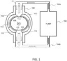
- a first embodiment of lithium hydride first wall device is shown in FIG. 1 .
- a pump 102 injects a liquid metal flow 111 (liquid metal mixture) by means of an outflow tube 104a (first tube) into a vessel 106.
- the outflow tube 104a may be split in two or more so that the liquid metal flow 111 may flow over the inner wall (s) 113 of the vessel 106.
- the liquid metal flow 111 may be filled with a plurality of pebbles 110.
- the liquid metal flow 111 returns to the pump by means of an inflow tube 104b.
- the inflow tube 104b (second tube) may have a plurality of inlets to collect the liquid metal flow 111 flowing over the inner walls 113 of the vessel 106.
- a plurality of electrodes 112 may be disposed on the inner wall 113 of the vessel 106.
- a magnetic field 108 (B) may be applied inside of the vessel 106.
- the electrodes may apply a current of density j, resulting in a force of density jxB, which forces the liquid metal flow to stick to the solid wall.
- the vessel forms at least part of a plasma confinement vessel.
- the vessel may form at least part of a nuclear reactor vessel, or of an isotopic separation chamber.
- the pump 102 may be fashioned to allow for circulation of high temperature liquid metals. Operating temperatures may be between 600°C and 900°C in fusion reactor applications.
- the inflow 104a and outflow 104b tubes are also adapted to operate at these temperatures.
- the inflow tube 104a takes the liquid metal flow 111 pumped from the pump 102 and services it to the inner wall(s) 113 of the vessel 106 from the top.
- the inner wall(s) 113 of the vessel 106 is (are) covered with the liquid metal flow 111. As the liquid metal 111 flows over the inner wall(s) 113, an outer surface 114 on the opposite side of the wall(s) 113 is formed by the liquid metal flow 111.
- the inflow tube 104a In order to ensure that the inner wall(s) 113 of the vessel is (are) completely covered, it may be necessary to split the inflow tube 104a or accommodate for receptacles to divide the flow over the wall.
- the liquid metal flow 111 is collected at the bottom of the vessel 106 by receptacles that service the outflow tube 104b.
- the outflow tube 104b takes the liquid metal flow 111 back into the pump where it may then be recirculated.
- the liquid metal flow 111 is primarily composed of a mixture of lithium and lithium hydride and may contain traces of other elements.
- the mixture of lithium and lithium hydride may be composed of at least 15% and at most 25% of lithium hydride, or at least 90% and at most 98%, this composition may be in the sense of molar content. Further, the mixture may contain lithium deuteride and/or lithium tritide. The content of the lithium hydride in the mixture allows for modification of the properties of the liquid metal flow 111. Changing the molar content of lithium hydride in the mixture modifies the attenuation and absorption properties of the liquid metal flow 111.
- the width of the liquid metal flow 111 as measured from the inner wall(s) 113 of the vessel 106 may be between 60 cm and 90 cm to effect optimum attenuation or absorption as required by the fusion reactor application while also accomplishing tritium breeding at an acceptable rate.
- the width of the liquid metal flow 111 as measured from the inner wall(s) 113 of the vessel 106 may be between 30 cm and 50 cm to effect optimum attenuation or absorption as required by the fusion reactor application while also accomplishing tritium breeding at an acceptable rate. It should be apparent to anyone proficient in the art that adding lithium tritide and/or lithium deuteride to the mixture produces the same or similar results.
- the vessel 106 may be shaped like a torus or in another similar shape. This shape would accommodate for fusion reactor applications.
- the inside of the vessel 106 is under the effect of a magnetic field 108.
- the magnetic field 108 is directed to the outside of the page.
- the magnetic field may be created by coils outside of the vessel 106 or some other appropriate method according to the application.
- the vessel 106 also contains a plurality of electrodes 112. Each of the electrodes 112 may be placed in a different location on the vessel 106 and they may be placed all over the inner wall(s) 113 of the vessel 106.
- the first embodiment includes a plurality of pebbles 110.
- the pebbles 110 are added to the liquid metal flow 111 prior to being loaded into the device or during operation.
- adequate hatchings or access points may be placed in the inflow tubes 104a.
- Each pebble 110 may have a different function and two main varieties are identified in this first embodiment.
- a first variety have the function of attenuation of neutrons and are henceforth called neutron attenuating.
- a second variety are called neutron multiplying and have the function of multiplying the number of neutrons inside the liquid first wall.
- the two varieties and their functions can be combined in a single type of pebbles, containing both neutron attenuating materials and neutron multiplying materials, or materials that can simultaneously attenuate neutrons and multiply them, like lead.
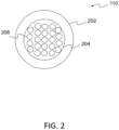
- FIG. 2 shows a cross sectional view of a pebble 110.
- the cross-sectional view of FIG. 2 is common to both varieties described.
- Each pebble 110 is constructed out of a core 204, and externally coated by an outer shell 202.
- Pebbles 110 may be constructed in a similar way to packed-bed beads that are common in nuclear fission applications.
- the outer shell 202 may be a coating of silicon carbide (SiC), graphite or other material suitable for stopping corrosion or interaction between lithium and the core 204.
- the core 204 may be of a different material according to the function of the pebble 110.
- the core 204 of a neutron attenuating pebble 110 may be constructed with lead or other materials of high atomic number, suitable for attenuating high energy neutrons.
- the core 204 of a neutron multiplying pebble 110 is constructed out of beryllium or other materials known for being adequate neutron multipliers.
- pebbles 110 may be sized between 1 mm and 5 mm
- the core 204 may be filled by pores 206, thus making it hollow, which enables making the pebble 110 lighter.
- the outer shell 202 may be an electrical insulator or a poor conductor, so that the pebble is not or less subject to electromagnetic forces. Therefore, the pebble will not be or be less pushed radially outward. Instead, the pebble may float on the liquid metal-facing side of the vessel, where it is most needed and most effective for attenuation and multiplication of high-energy neutrons.
- a pump 102 injects a liquid metal flow 111 to the inner wall(s) 113 of a vessel 106.
- the vessel 106 is shaped like a torus and as such is hollow in the inside.
- Said liquid metal is a mixture of lithium and lithium hydride and may contain lithium deuteride and/or lithium tritide. Injection is made from the top of the vessel 106.
- the liquid metal flow 111 may preferably be injected with a sufficiently high tangential velocity so that it may adhere to the inner wall(s) 113 by effect of a centrifugal force. Adherence to the inner wall(s) 113 is further maintained by the application of an electric current through the use of electrodes 112. An electric current is made circulate inside the liquid metal flow 111 in the poloidal direction. A magnetic field 108 is also applied in the toroidal direction. The interaction of the current and the magnetic field 108 causes an electromagnetic force that pushes the liquid metal flow 111 further into the inner wall 113.
- the action of the centrifugal and electromagnetic forces creates a situation of artificial gravity resulting in the pebbles 110 floating to the outer surface 114 of the liquid metal flow 111. This is due either to lower density (obtained by porosity) and/or to the outer shell 202 being an electrical insulator or a poor conductor, thus making the pebbles 110 at least partially immune to electromagnetic forces.
- the outer surface 114 of the liquid metal flow 111 is the one that faces the inside of the toroidal vessel 106. In the fusion reactor, a fusion reaction takes place in the inside of the vessel 106. Neutrons and other particles are ejected with high energy towards the outer surface 114 of the liquid metal flow 111.
- Neutrons interact with the pebbles 110, according to their function they result in attenuation of the neutrons or multiplication of the neutrons. Further, neutrons interact with the lithium and lithium hydride mixture in the liquid metal flow 111 resulting in further absorption and tritium breeding.
- the liquid metal flow 111 is at a high temperature after this process.
- the liquid metal flow 111 is collected at the bottom of the vessel 106.
- the outflow tubes 104b then take the collected liquid metal flow and service other devices.
- other embodiments may include a heat exchanger, separators, or combinations of such, so that energy may be extracted from the liquid metal flow 111.
- the liquid metal flow is again serviced to the pump 102 and the process may continue.
- the tritium breeding characteristics of the disclosed lithium hydride first wall depend on the composition and amount of pebbles 110 and the composition of the lithium hydride mixture in the liquid metal flow 111. Therefore, by modifying the pebbles 110 or the composition the size of the liquid metal flow 111 may be modified and the size of a vessel 106 that uses the described lithium hydride first wall may be made smaller than what is currently being designed and constructed.
- the lithium hydride content in the liquid metal flow 111 is as high as 90% or even further.
- the width of the liquid metal flow 111 when measured from the inner wall 113 may be as low as few millimeters in order to achieve acceptable tritium breeding rates.
- the outflow tube 104b takes the liquid metal flow 111 and delivers it to another device.
- this other device could be a heat exchanger that would remove the heat from the liquid metal 111 and exchange it with a different fluid, this could be part of a power generation plant.
- the pores 206 inside the pebble 110 are not located in the core 204, but on the outer shell 202. In yet another embodiment pores 206 are located not only on the core 204 but also in the outer shell 202.
Landscapes
- Physics & Mathematics (AREA)
- Engineering & Computer Science (AREA)
- Plasma & Fusion (AREA)
- General Engineering & Computer Science (AREA)
- High Energy & Nuclear Physics (AREA)
- Physical Or Chemical Processes And Apparatus (AREA)
- Particle Accelerators (AREA)
Claims (18)
- Eine erste Wand, die geeignet ist, eine Innenwand (113) eines Plasmaeinschlussbehälters (106) zu bedecken, wobei die erste Wand aus einer Metallmischung (111) hergestellt ist, die mindestens Lithium und Lithiumhydrid aufweist, wobei die Metallmischung (111) im Betrieb flüssig ist, wobei die erste Wand ferner Kugeln (110) aufweist, die in der flüssigen Metallmischung (111) suspendiert sind, wobei jede Kugel eine neutronendämpfende Kugel, eine neutronenvervielfachende Kugel oder eine neutronendämpfende und -vervielfachende Kugel ist.
- Erste Wand nach Anspruch 1, wobei die Kugeln (110) eine Größe zwischen 1 und 5 mm haben.
- Erste Wand nach Anspruch 1 oder 2, wobei mindestens einer der Kugeln (110) einen Kern (204) aufweist, der von einer Außenhülle (202) ummantelt ist.
- Erste Wand nach Anspruch 3, wobei der Kern (204) ein ausgehöhlter, beispielsweise mit Poren (206) gefüllter Kern ist und/oder die Außenhülle (202) eine ausgehöhlte, beispielsweise mit Poren gefüllte Hülle ist.
- Erste Wand nach Anspruch 3 oder 4, wobei:- mindestens eine der Kugeln (110) eine neutronendämpfende Kugel ist und der Kern (204) der neutronendämpfenden Kugel primär ein zur Dämpfung von Neutronen geeignetes Material, vorzugsweise ein Material mit hoher Ordnungszahl, zum Beispiel Blei, aufweist; und/oder- mindestens einer der Kugeln (110) eine Neutronenvervielfachungskugel ist und der Kern (204) der Neutronenvervielfachungskugel in erster Linie ein Material aufweist, das zur Vervielfachung von Neutronen geeignet ist, beispielsweise Beryllium; und/oder die äußere Hülle (202) in erster Linie ein Material aufweist, das geeignet ist, die Korrosion und/oder die Wechselwirkung zwischen Lithium und dem Kern (204) zu stoppen, beispielsweise Siliziumkarbid oder Graphit.
- Erste Wand nach einem der Ansprüche 1 bis 5, wobei zumindest einige der Kugeln (110) an einer äußeren Oberfläche (114) der flüssigen Metallmischung (111) angeordnet sind.
- Erste Wand nach einem der Ansprüche 1 bis 6, wobei die Mischung ferner Lithiumtritid und/oder Lithiumdeuterid aufweist.
- Erste Wand nach einem der Ansprüche 1 bis 7, wobei die Mischung zwischen 15 und 25 Mol-% Lithiumhydrid, Lithiumtritid und/oder Lithiumdeuterid aufweist und die Breite der ersten Wand beispielsweise zwischen 60 und 90 Zentimetern liegt; oder die Mischung zwischen 90 und 98 Mol-% Lithiumhydrid, Lithiumtritid und/oder Lithiumdeuterid aufweist und die Breite der ersten Wand beispielsweise zwischen 30 und 50 Zentimetern liegt.
- Behälter (106) mit einer Innenwand (113), wobei die Innenwand mit einer ersten Wand nach einem der Ansprüche 1 bis 8 bedeckt ist.
- Eine erste Wand-Vorrichtung zur Bildung einer ersten Wand nach einem der Ansprüche 1 bis 8, wobei die Vorrichtung Folgendes aufweist:- einen Behälter (106) mit einer Innenwand (113);- Strömungseinrichtung (102, 104a, 104b), die geeignet ist zum Ausbilden einer Strömung einer flüssigen Metallmischung (111) an der Innenwand (113); wobei die Strömungseinrichtung Mittel zum Hinzufügen von Kugeln (110) zu der flüssigen Metallmischung aufweist, wobei jede Kugel eine neutronenabschwächende Kugel, eine neutronenvervielfachende Kugel oder eine neutronenabschwächende und -vervielfachende Kugel ist.
- Vorrichtung nach Anspruch 10, wobei die Strömungseinrichtung Folgendes aufweist:- eine Pumpe (102);- ein erstes Rohr (104a) zwischen der Pumpe und dem Behälter (106), wobei das erste Rohr geeignet ist zum Einspritzen der flüssigen Metallmischung (111) über die Innenwand (113), wobei das erste Rohr beispielsweise in mindestens zwei Teile im Behälter unterteilt ist; und- ein zweites Rohr (104b) zwischen dem Behälter (106) und der Pumpe (102), wobei das zweite Rohr geeignet ist zum Auffange der über die Innenwand (113) fließenden flüssigen Metallmischung (111), wobei das zweite Rohr beispielsweise in mindestens zwei Teile im Behälter unterteilt ist.
- Vorrichtung nach Anspruch 10 oder 11, wobei die Strömungseinrichtung:- geeignet ist zum Zirkulieren der flüssigen Metallmischung (111) bei hohen Temperaturen, beispielsweise bei Temperaturen zwischen 600°C und 900°C; und/oder- Mittel zum Hinzufügen von Kugeln (110) zu der flüssigen Metallmischung (111) aufweist, beispielsweise Luken oder Zugangspunkte in einem ersten Rohr (104a) der Strömungseinrichtung.
- Vorrichtung nach einem der Ansprüche 10 bis 12 oder der Behälter nach Anspruch 9 ferner aufweisend Elektroden (112), die an der Innenwand (113) des Behälters (106) angeordnet sind, wobei die Elektroden so beschaffen sind, dass sie einen elektrischen Strom an die flüssige Metallmischung (111) der ersten Wand anlegen.
- Vorrichtung nach einem der Ansprüche 10 bis 13 oder der Behälter nach Anspruch 9 oder 13 ferner aufweisend Mittel zum Erzeugen eines Magnetfeldes (108) im Inneren des Behälters.
- Vorrichtung nach einem der Ansprüche 10 bis 14 oder der Behälter nach einem der Ansprüche 9, 13, 14, wobei der Behälter (106) im Wesentlichen die Form eines Torus hat.
- Vorrichtung nach einem der Ansprüche 10 bis 15 oder der Behälter nach einem der Ansprüche 9, 13 bis 15, wobei der Behälter (106) zumindest einen Teil eines Plasmaeinschlussbehälters, eines Kernreaktorbehälters oder einer Isotopentrennkammer bildet.
- Ein Verfahren zur Bildung einer ersten Wand nach einem der Ansprüche 1 bis 8, wobei das Verfahren Folgendes aufweist:- Einspritzen einer flüssigen Metallmischung (111) in eine Innenwand (113) eines Behälters (106), wobei die flüssige Metallmischung (111) mindestens Lithium und Lithiumhydrid enthält; und- Einspritzen von Kugeln (110) in die flüssige Metallmischung vor oder während des Einspritzschritts, wobei jede Kugel eine neutronendämpfende Kugel, eine neutronenvervielfachende Kugel oder eine neutronendämpfende und - vervielfachende Kugel ist.
- Verfahren nach Anspruch 17, wobei das Verfahren ferner Folgendes aufweist:- Anlegen eines elektrischen Stroms an die flüssige Metallmischung (111) während des Einspritzschritts, beispielsweise durch die Verwendung von Elektroden (112), die sich an der Innenwand (113) des Behälters (106) befinden;- Anlegen eines Magnetfeldes in dem Behälter (106) während des Einspritzschritts;- Einspritzen von Kugeln (110) in die flüssige Metallmischung (111) vor oder während des Einspritzschritts, wobei jede Kugel eine neutronendämpfende Kugel, eine neutronenvervielfachende Kugel oder eine neutronendämpfende und -vervielfachende Kugel ist; und/oder- Sammeln der flüssigen Metallmischung (111) aus dem Behälter (106) nach dem Einspritzschritt und Weiterleiten der gesammelten flüssigen Metallmischung für einen weiteren Einspritzschritt in den Behälter (106) und/oder zu einer anderen Vorrichtung, die geeignet ist, Energie aus der gesammelten flüssigen Metallmischung zu gewinnen, wie z.B. einem Wärmetauscher oder einem Separator.
Priority Applications (6)
| Application Number | Priority Date | Filing Date | Title |
|---|---|---|---|
| EP22305451.1A EP4258286B1 (de) | 2022-04-04 | 2022-04-04 | Lithiumhydrid-erstwand |
| US18/850,486 US20250218608A1 (en) | 2022-04-04 | 2023-04-04 | Lithium hydride first wall |
| EP23716873.7A EP4505486A1 (de) | 2022-04-04 | 2023-04-04 | Erste wand aus lithiumhydrid |
| PCT/EP2023/058832 WO2023194373A1 (en) | 2022-04-04 | 2023-04-04 | Lithium hydride first wall |
| JP2024559544A JP2025513015A (ja) | 2022-04-04 | 2023-04-04 | 水素化リチウム第一壁 |
| CN202380030930.9A CN119137682A (zh) | 2022-04-04 | 2023-04-04 | 氢化锂第一壁 |
Applications Claiming Priority (1)
| Application Number | Priority Date | Filing Date | Title |
|---|---|---|---|
| EP22305451.1A EP4258286B1 (de) | 2022-04-04 | 2022-04-04 | Lithiumhydrid-erstwand |
Publications (3)
| Publication Number | Publication Date |
|---|---|
| EP4258286A1 EP4258286A1 (de) | 2023-10-11 |
| EP4258286B1 true EP4258286B1 (de) | 2024-10-30 |
| EP4258286C0 EP4258286C0 (de) | 2024-10-30 |
Family
ID=82258500
Family Applications (2)
| Application Number | Title | Priority Date | Filing Date |
|---|---|---|---|
| EP22305451.1A Active EP4258286B1 (de) | 2022-04-04 | 2022-04-04 | Lithiumhydrid-erstwand |
| EP23716873.7A Pending EP4505486A1 (de) | 2022-04-04 | 2023-04-04 | Erste wand aus lithiumhydrid |
Family Applications After (1)
| Application Number | Title | Priority Date | Filing Date |
|---|---|---|---|
| EP23716873.7A Pending EP4505486A1 (de) | 2022-04-04 | 2023-04-04 | Erste wand aus lithiumhydrid |
Country Status (5)
| Country | Link |
|---|---|
| US (1) | US20250218608A1 (de) |
| EP (2) | EP4258286B1 (de) |
| JP (1) | JP2025513015A (de) |
| CN (1) | CN119137682A (de) |
| WO (1) | WO2023194373A1 (de) |
Citations (2)
| Publication number | Priority date | Publication date | Assignee | Title |
|---|---|---|---|---|
| JPH0882688A (ja) * | 1994-09-14 | 1996-03-26 | Toshiba Corp | 核融合炉の増殖ブランケット |
| WO2022106609A1 (en) * | 2020-11-19 | 2022-05-27 | Tokamak Energy Ltd | Breeder blanket |
Family Cites Families (4)
| Publication number | Priority date | Publication date | Assignee | Title |
|---|---|---|---|---|
| US4344911A (en) | 1977-11-14 | 1982-08-17 | The United States Of America As Represented By The United States Department Of Energy | Fluidized wall for protecting fusion chamber walls |
| US5958105A (en) | 1996-09-11 | 1999-09-28 | Japan Atomic Energy Research Institute | Process for preparing metallic beryllium pebbles |
| US6411666B1 (en) * | 1998-10-21 | 2002-06-25 | The United States Of America As Represented By The United States Department Of Energy | Method and apparatus to produce and maintain a thick, flowing, liquid lithium first wall for toroidal magnetic confinement DT fusion reactors |
| US20080093585A1 (en) * | 2006-10-23 | 2008-04-24 | Pereira Nino R | Dispersion Strengthened Lithium and Method Therefor |
-
2022
- 2022-04-04 EP EP22305451.1A patent/EP4258286B1/de active Active
-
2023
- 2023-04-04 WO PCT/EP2023/058832 patent/WO2023194373A1/en not_active Ceased
- 2023-04-04 EP EP23716873.7A patent/EP4505486A1/de active Pending
- 2023-04-04 US US18/850,486 patent/US20250218608A1/en active Pending
- 2023-04-04 JP JP2024559544A patent/JP2025513015A/ja active Pending
- 2023-04-04 CN CN202380030930.9A patent/CN119137682A/zh active Pending
Patent Citations (2)
| Publication number | Priority date | Publication date | Assignee | Title |
|---|---|---|---|---|
| JPH0882688A (ja) * | 1994-09-14 | 1996-03-26 | Toshiba Corp | 核融合炉の増殖ブランケット |
| WO2022106609A1 (en) * | 2020-11-19 | 2022-05-27 | Tokamak Energy Ltd | Breeder blanket |
Also Published As
| Publication number | Publication date |
|---|---|
| WO2023194373A1 (en) | 2023-10-12 |
| EP4505486A1 (de) | 2025-02-12 |
| US20250218608A1 (en) | 2025-07-03 |
| EP4258286A1 (de) | 2023-10-11 |
| JP2025513015A (ja) | 2025-04-22 |
| CN119137682A (zh) | 2024-12-13 |
| EP4258286C0 (de) | 2024-10-30 |
Similar Documents
| Publication | Publication Date | Title |
|---|---|---|
| RU2608082C2 (ru) | Двухфлюидный реактор | |
| CN104240772B (zh) | Z箍缩驱动聚变裂变混合能源堆 | |
| KR20190003704A (ko) | 중성자 반사 냉각제를 갖는 용융 연료 원자로 | |
| EP4248462B1 (de) | Brütermantel für fusionsreaktor und verfahren zum betrieb eines fusionsreaktors mit einem solchen brütermantel | |
| CN1319074C (zh) | 采用套管燃料组件的超临界水核反应堆 | |
| Zhang et al. | Liquid metals power advanced nuclear energy systems | |
| EP4258286B1 (de) | Lithiumhydrid-erstwand | |
| Monsler et al. | Electric power from laser fusion: the HYLIFE concept | |
| Wang et al. | Neutron physics of the liquid‐fuel heat‐pipe reactor concept with molten salt fuel—Static calculations | |
| Dulera et al. | Compact high temperature reactor (CHTR) | |
| Hogan et al. | Advances in ICF power reactor design | |
| CN118231009A (zh) | 通过反应堆衰变热去除(dhr)系统在反应堆容器周围具有填充有惰性液体盐的容器的快中子反应堆类型的熔盐核反应堆 | |
| CN104157312A (zh) | 模块式基于z箍缩驱动的聚变裂变混合堆包层燃料区 | |
| Maniscalco et al. | A laser fusion power plant based on a fluid wall reactor concept | |
| CN112599259A (zh) | 一种聚变-裂变混合堆嬗变燃料组件 | |
| Wu | Neutronics Design Principles of Fusion-Fission Hybrid Reactors | |
| US20260120897A1 (en) | Nuclear reactor fuel and associated systems and methods | |
| RU2032946C1 (ru) | Водоохлаждаемый ядерный реактор | |
| Horiike et al. | Liquid metal cooling issues for fusion and fission | |
| Werley | A high-speed beam of lithium droplets for collecting diverted energy and particles in ITER | |
| Brasier et al. | Application of Low Critical Mass Studies to Reactor Design | |
| Monsler et al. | Electric power from inertial confinement fusion: the HYLIFE concept | |
| KE et al. | HIGH POWER DENSITY EFFECTS ON THE KEY COMPONENT DESIGN | |
| Sembiring et al. | Thermal Hydraulics Analyses on the Core of HTR-10 in Steady State and Transient Conditions Using Fluent 6.3 3-Dimensional Model for Indonesian RDE Design Development | |
| KR101744156B1 (ko) | 개량형 중수로용 핵연료 다발 |
Legal Events
| Date | Code | Title | Description |
|---|---|---|---|
| PUAI | Public reference made under article 153(3) epc to a published international application that has entered the european phase |
Free format text: ORIGINAL CODE: 0009012 |
|
| STAA | Information on the status of an ep patent application or granted ep patent |
Free format text: STATUS: THE APPLICATION HAS BEEN PUBLISHED |
|
| AK | Designated contracting states |
Kind code of ref document: A1 Designated state(s): AL AT BE BG CH CY CZ DE DK EE ES FI FR GB GR HR HU IE IS IT LI LT LU LV MC MK MT NL NO PL PT RO RS SE SI SK SM TR |
|
| STAA | Information on the status of an ep patent application or granted ep patent |
Free format text: STATUS: REQUEST FOR EXAMINATION WAS MADE |
|
| 17P | Request for examination filed |
Effective date: 20231229 |
|
| RBV | Designated contracting states (corrected) |
Designated state(s): AL AT BE BG CH CY CZ DE DK EE ES FI FR GB GR HR HU IE IS IT LI LT LU LV MC MK MT NL NO PL PT RO RS SE SI SK SM TR |
|
| GRAP | Despatch of communication of intention to grant a patent |
Free format text: ORIGINAL CODE: EPIDOSNIGR1 |
|
| STAA | Information on the status of an ep patent application or granted ep patent |
Free format text: STATUS: GRANT OF PATENT IS INTENDED |
|
| INTG | Intention to grant announced |
Effective date: 20240529 |
|
| GRAS | Grant fee paid |
Free format text: ORIGINAL CODE: EPIDOSNIGR3 |
|
| GRAA | (expected) grant |
Free format text: ORIGINAL CODE: 0009210 |
|
| STAA | Information on the status of an ep patent application or granted ep patent |
Free format text: STATUS: THE PATENT HAS BEEN GRANTED |
|
| GRAT | Correction requested after decision to grant or after decision to maintain patent in amended form |
Free format text: ORIGINAL CODE: EPIDOSNCDEC |
|
| AK | Designated contracting states |
Kind code of ref document: B1 Designated state(s): AL AT BE BG CH CY CZ DE DK EE ES FI FR GB GR HR HU IE IS IT LI LT LU LV MC MK MT NL NO PL PT RO RS SE SI SK SM TR |
|
| REG | Reference to a national code |
Ref country code: GB Ref legal event code: FG4D |
|
| REG | Reference to a national code |
Ref country code: CH Ref legal event code: EP |
|
| RAP4 | Party data changed (patent owner data changed or rights of a patent transferred) |
Owner name: RENAISSANCE FUSION |
|
| REG | Reference to a national code |
Ref country code: DE Ref legal event code: R096 Ref document number: 602022007255 Country of ref document: DE |
|
| REG | Reference to a national code |
Ref country code: IE Ref legal event code: FG4D |
|
| U01 | Request for unitary effect filed |
Effective date: 20241126 |
|
| U07 | Unitary effect registered |
Designated state(s): AT BE BG DE DK EE FI FR IT LT LU LV MT NL PT RO SE SI Effective date: 20241202 |
|
| U20 | Renewal fee for the european patent with unitary effect paid |
Year of fee payment: 4 Effective date: 20250225 |
|
| PG25 | Lapsed in a contracting state [announced via postgrant information from national office to epo] |
Ref country code: HR Free format text: LAPSE BECAUSE OF FAILURE TO SUBMIT A TRANSLATION OF THE DESCRIPTION OR TO PAY THE FEE WITHIN THE PRESCRIBED TIME-LIMIT Effective date: 20241030 Ref country code: IS Free format text: LAPSE BECAUSE OF FAILURE TO SUBMIT A TRANSLATION OF THE DESCRIPTION OR TO PAY THE FEE WITHIN THE PRESCRIBED TIME-LIMIT Effective date: 20250228 |
|
| PG25 | Lapsed in a contracting state [announced via postgrant information from national office to epo] |
Ref country code: ES Free format text: LAPSE BECAUSE OF FAILURE TO SUBMIT A TRANSLATION OF THE DESCRIPTION OR TO PAY THE FEE WITHIN THE PRESCRIBED TIME-LIMIT Effective date: 20241030 |
|
| PG25 | Lapsed in a contracting state [announced via postgrant information from national office to epo] |
Ref country code: NO Free format text: LAPSE BECAUSE OF FAILURE TO SUBMIT A TRANSLATION OF THE DESCRIPTION OR TO PAY THE FEE WITHIN THE PRESCRIBED TIME-LIMIT Effective date: 20250130 |
|
| PG25 | Lapsed in a contracting state [announced via postgrant information from national office to epo] |
Ref country code: GR Free format text: LAPSE BECAUSE OF FAILURE TO SUBMIT A TRANSLATION OF THE DESCRIPTION OR TO PAY THE FEE WITHIN THE PRESCRIBED TIME-LIMIT Effective date: 20250131 |
|
| PG25 | Lapsed in a contracting state [announced via postgrant information from national office to epo] |
Ref country code: PL Free format text: LAPSE BECAUSE OF FAILURE TO SUBMIT A TRANSLATION OF THE DESCRIPTION OR TO PAY THE FEE WITHIN THE PRESCRIBED TIME-LIMIT Effective date: 20241030 |
|
| PG25 | Lapsed in a contracting state [announced via postgrant information from national office to epo] |
Ref country code: RS Free format text: LAPSE BECAUSE OF FAILURE TO SUBMIT A TRANSLATION OF THE DESCRIPTION OR TO PAY THE FEE WITHIN THE PRESCRIBED TIME-LIMIT Effective date: 20250130 |
|
| PG25 | Lapsed in a contracting state [announced via postgrant information from national office to epo] |
Ref country code: SM Free format text: LAPSE BECAUSE OF FAILURE TO SUBMIT A TRANSLATION OF THE DESCRIPTION OR TO PAY THE FEE WITHIN THE PRESCRIBED TIME-LIMIT Effective date: 20241030 |
|
| PG25 | Lapsed in a contracting state [announced via postgrant information from national office to epo] |
Ref country code: SK Free format text: LAPSE BECAUSE OF FAILURE TO SUBMIT A TRANSLATION OF THE DESCRIPTION OR TO PAY THE FEE WITHIN THE PRESCRIBED TIME-LIMIT Effective date: 20241030 |
|
| PG25 | Lapsed in a contracting state [announced via postgrant information from national office to epo] |
Ref country code: CZ Free format text: LAPSE BECAUSE OF FAILURE TO SUBMIT A TRANSLATION OF THE DESCRIPTION OR TO PAY THE FEE WITHIN THE PRESCRIBED TIME-LIMIT Effective date: 20241030 |
|
| PLBE | No opposition filed within time limit |
Free format text: ORIGINAL CODE: 0009261 |
|
| STAA | Information on the status of an ep patent application or granted ep patent |
Free format text: STATUS: NO OPPOSITION FILED WITHIN TIME LIMIT |
|
| 26N | No opposition filed |
Effective date: 20250731 |
|
| REG | Reference to a national code |
Ref country code: CH Ref legal event code: H13 Free format text: ST27 STATUS EVENT CODE: U-0-0-H10-H13 (AS PROVIDED BY THE NATIONAL OFFICE) Effective date: 20251125 |
|
| PG25 | Lapsed in a contracting state [announced via postgrant information from national office to epo] |
Ref country code: MC Free format text: LAPSE BECAUSE OF FAILURE TO SUBMIT A TRANSLATION OF THE DESCRIPTION OR TO PAY THE FEE WITHIN THE PRESCRIBED TIME-LIMIT Effective date: 20241030 |
|
| PG25 | Lapsed in a contracting state [announced via postgrant information from national office to epo] |
Ref country code: CH Free format text: LAPSE BECAUSE OF NON-PAYMENT OF DUE FEES Effective date: 20250430 |
|
| U20 | Renewal fee for the european patent with unitary effect paid |
Year of fee payment: 5 Effective date: 20260226 |
|
| PG25 | Lapsed in a contracting state [announced via postgrant information from national office to epo] |
Ref country code: IE Free format text: LAPSE BECAUSE OF NON-PAYMENT OF DUE FEES Effective date: 20250404 |