EP4258159B1 - Verfahren zur identifizierung und nachverfolgung von vereinzelt geförderten produkten - Google Patents
Verfahren zur identifizierung und nachverfolgung von vereinzelt geförderten produkten Download PDFInfo
- Publication number
- EP4258159B1 EP4258159B1 EP22166717.3A EP22166717A EP4258159B1 EP 4258159 B1 EP4258159 B1 EP 4258159B1 EP 22166717 A EP22166717 A EP 22166717A EP 4258159 B1 EP4258159 B1 EP 4258159B1
- Authority
- EP
- European Patent Office
- Prior art keywords
- product
- camera
- products
- view
- transport device
- Prior art date
- Legal status (The legal status is an assumption and is not a legal conclusion. Google has not performed a legal analysis and makes no representation as to the accuracy of the status listed.)
- Active
Links
Images

Classifications
-
- B—PERFORMING OPERATIONS; TRANSPORTING
- B65—CONVEYING; PACKING; STORING; HANDLING THIN OR FILAMENTARY MATERIAL
- B65G—TRANSPORT OR STORAGE DEVICES, e.g. CONVEYORS FOR LOADING OR TIPPING, SHOP CONVEYOR SYSTEMS OR PNEUMATIC TUBE CONVEYORS
- B65G47/00—Article or material-handling devices associated with conveyors; Methods employing such devices
- B65G47/74—Feeding, transfer, or discharging devices of particular kinds or types
-
- G—PHYSICS
- G06—COMPUTING OR CALCULATING; COUNTING
- G06K—GRAPHICAL DATA READING; PRESENTATION OF DATA; RECORD CARRIERS; HANDLING RECORD CARRIERS
- G06K7/00—Methods or arrangements for sensing record carriers, e.g. for reading patterns
- G06K7/10—Methods or arrangements for sensing record carriers, e.g. for reading patterns by electromagnetic radiation, e.g. optical sensing; by corpuscular radiation
- G06K7/10009—Methods or arrangements for sensing record carriers, e.g. for reading patterns by electromagnetic radiation, e.g. optical sensing; by corpuscular radiation sensing by radiation using wavelengths larger than 0.1 mm, e.g. radio-waves or microwaves
- G06K7/10366—Methods or arrangements for sensing record carriers, e.g. for reading patterns by electromagnetic radiation, e.g. optical sensing; by corpuscular radiation sensing by radiation using wavelengths larger than 0.1 mm, e.g. radio-waves or microwaves the interrogation device being adapted for miscellaneous applications
- G06K7/10415—Methods or arrangements for sensing record carriers, e.g. for reading patterns by electromagnetic radiation, e.g. optical sensing; by corpuscular radiation sensing by radiation using wavelengths larger than 0.1 mm, e.g. radio-waves or microwaves the interrogation device being adapted for miscellaneous applications the interrogation device being fixed in its position, such as an access control device for reading wireless access cards, or a wireless ATM
- G06K7/10425—Methods or arrangements for sensing record carriers, e.g. for reading patterns by electromagnetic radiation, e.g. optical sensing; by corpuscular radiation sensing by radiation using wavelengths larger than 0.1 mm, e.g. radio-waves or microwaves the interrogation device being adapted for miscellaneous applications the interrogation device being fixed in its position, such as an access control device for reading wireless access cards, or a wireless ATM the interrogation device being arranged for interrogation of record carriers passing by the interrogation device
- G06K7/10435—Methods or arrangements for sensing record carriers, e.g. for reading patterns by electromagnetic radiation, e.g. optical sensing; by corpuscular radiation sensing by radiation using wavelengths larger than 0.1 mm, e.g. radio-waves or microwaves the interrogation device being adapted for miscellaneous applications the interrogation device being fixed in its position, such as an access control device for reading wireless access cards, or a wireless ATM the interrogation device being arranged for interrogation of record carriers passing by the interrogation device the interrogation device being positioned close to a conveyor belt or the like on which moving record carriers are passing
- G06K7/10445—Methods or arrangements for sensing record carriers, e.g. for reading patterns by electromagnetic radiation, e.g. optical sensing; by corpuscular radiation sensing by radiation using wavelengths larger than 0.1 mm, e.g. radio-waves or microwaves the interrogation device being adapted for miscellaneous applications the interrogation device being fixed in its position, such as an access control device for reading wireless access cards, or a wireless ATM the interrogation device being arranged for interrogation of record carriers passing by the interrogation device the interrogation device being positioned close to a conveyor belt or the like on which moving record carriers are passing the record carriers being fixed to further objects, e.g. RFIDs fixed to packages, luggage, mail-pieces or work-pieces transported on a conveyor belt
-
- G—PHYSICS
- G06—COMPUTING OR CALCULATING; COUNTING
- G06K—GRAPHICAL DATA READING; PRESENTATION OF DATA; RECORD CARRIERS; HANDLING RECORD CARRIERS
- G06K7/00—Methods or arrangements for sensing record carriers, e.g. for reading patterns
- G06K7/10—Methods or arrangements for sensing record carriers, e.g. for reading patterns by electromagnetic radiation, e.g. optical sensing; by corpuscular radiation
- G06K7/14—Methods or arrangements for sensing record carriers, e.g. for reading patterns by electromagnetic radiation, e.g. optical sensing; by corpuscular radiation using light without selection of wavelength, e.g. sensing reflected white light
- G06K7/1404—Methods for optical code recognition
- G06K7/1408—Methods for optical code recognition the method being specifically adapted for the type of code
- G06K7/1417—2D bar codes
-
- B—PERFORMING OPERATIONS; TRANSPORTING
- B65—CONVEYING; PACKING; STORING; HANDLING THIN OR FILAMENTARY MATERIAL
- B65G—TRANSPORT OR STORAGE DEVICES, e.g. CONVEYORS FOR LOADING OR TIPPING, SHOP CONVEYOR SYSTEMS OR PNEUMATIC TUBE CONVEYORS
- B65G43/00—Control devices, e.g. for safety, warning or fault-correcting
- B65G43/08—Control devices operated by article or material being fed, conveyed or discharged
-
- B—PERFORMING OPERATIONS; TRANSPORTING
- B65—CONVEYING; PACKING; STORING; HANDLING THIN OR FILAMENTARY MATERIAL
- B65G—TRANSPORT OR STORAGE DEVICES, e.g. CONVEYORS FOR LOADING OR TIPPING, SHOP CONVEYOR SYSTEMS OR PNEUMATIC TUBE CONVEYORS
- B65G47/00—Article or material-handling devices associated with conveyors; Methods employing such devices
- B65G47/22—Devices influencing the relative position or the attitude of articles during transit by conveyors
- B65G47/24—Devices influencing the relative position or the attitude of articles during transit by conveyors orientating the articles
- B65G47/244—Devices influencing the relative position or the attitude of articles during transit by conveyors orientating the articles by turning them about an axis substantially perpendicular to the conveying plane
-
- G—PHYSICS
- G06—COMPUTING OR CALCULATING; COUNTING
- G06K—GRAPHICAL DATA READING; PRESENTATION OF DATA; RECORD CARRIERS; HANDLING RECORD CARRIERS
- G06K19/00—Record carriers for use with machines and with at least a part designed to carry digital markings
- G06K19/06—Record carriers for use with machines and with at least a part designed to carry digital markings characterised by the kind of the digital marking, e.g. shape, nature, code
- G06K19/06009—Record carriers for use with machines and with at least a part designed to carry digital markings characterised by the kind of the digital marking, e.g. shape, nature, code with optically detectable marking
- G06K19/06037—Record carriers for use with machines and with at least a part designed to carry digital markings characterised by the kind of the digital marking, e.g. shape, nature, code with optically detectable marking multi-dimensional coding
-
- G—PHYSICS
- G06—COMPUTING OR CALCULATING; COUNTING
- G06K—GRAPHICAL DATA READING; PRESENTATION OF DATA; RECORD CARRIERS; HANDLING RECORD CARRIERS
- G06K7/00—Methods or arrangements for sensing record carriers, e.g. for reading patterns
- G06K7/10—Methods or arrangements for sensing record carriers, e.g. for reading patterns by electromagnetic radiation, e.g. optical sensing; by corpuscular radiation
- G06K7/10544—Methods or arrangements for sensing record carriers, e.g. for reading patterns by electromagnetic radiation, e.g. optical sensing; by corpuscular radiation by scanning of the records by radiation in the optical part of the electromagnetic spectrum
- G06K7/10821—Methods or arrangements for sensing record carriers, e.g. for reading patterns by electromagnetic radiation, e.g. optical sensing; by corpuscular radiation by scanning of the records by radiation in the optical part of the electromagnetic spectrum further details of bar or optical code scanning devices
- G06K7/10861—Methods or arrangements for sensing record carriers, e.g. for reading patterns by electromagnetic radiation, e.g. optical sensing; by corpuscular radiation by scanning of the records by radiation in the optical part of the electromagnetic spectrum further details of bar or optical code scanning devices sensing of data fields affixed to objects or articles, e.g. coded labels
-
- G—PHYSICS
- G06—COMPUTING OR CALCULATING; COUNTING
- G06K—GRAPHICAL DATA READING; PRESENTATION OF DATA; RECORD CARRIERS; HANDLING RECORD CARRIERS
- G06K7/00—Methods or arrangements for sensing record carriers, e.g. for reading patterns
- G06K7/10—Methods or arrangements for sensing record carriers, e.g. for reading patterns by electromagnetic radiation, e.g. optical sensing; by corpuscular radiation
- G06K7/10544—Methods or arrangements for sensing record carriers, e.g. for reading patterns by electromagnetic radiation, e.g. optical sensing; by corpuscular radiation by scanning of the records by radiation in the optical part of the electromagnetic spectrum
- G06K7/10821—Methods or arrangements for sensing record carriers, e.g. for reading patterns by electromagnetic radiation, e.g. optical sensing; by corpuscular radiation by scanning of the records by radiation in the optical part of the electromagnetic spectrum further details of bar or optical code scanning devices
- G06K7/1096—Methods or arrangements for sensing record carriers, e.g. for reading patterns by electromagnetic radiation, e.g. optical sensing; by corpuscular radiation by scanning of the records by radiation in the optical part of the electromagnetic spectrum further details of bar or optical code scanning devices the scanner having more than one scanning window, e.g. two substantially orthogonally placed scanning windows for integration into a check-out counter of a super-market
-
- B—PERFORMING OPERATIONS; TRANSPORTING
- B65—CONVEYING; PACKING; STORING; HANDLING THIN OR FILAMENTARY MATERIAL
- B65G—TRANSPORT OR STORAGE DEVICES, e.g. CONVEYORS FOR LOADING OR TIPPING, SHOP CONVEYOR SYSTEMS OR PNEUMATIC TUBE CONVEYORS
- B65G2201/00—Indexing codes relating to handling devices, e.g. conveyors, characterised by the type of product or load being conveyed or handled
- B65G2201/02—Articles
- B65G2201/0214—Articles of special size, shape or weigh
-
- B—PERFORMING OPERATIONS; TRANSPORTING
- B65—CONVEYING; PACKING; STORING; HANDLING THIN OR FILAMENTARY MATERIAL
- B65G—TRANSPORT OR STORAGE DEVICES, e.g. CONVEYORS FOR LOADING OR TIPPING, SHOP CONVEYOR SYSTEMS OR PNEUMATIC TUBE CONVEYORS
- B65G2203/00—Indexing code relating to control or detection of the articles or the load carriers during conveying
- B65G2203/02—Control or detection
- B65G2203/0208—Control or detection relating to the transported articles
- B65G2203/0216—Codes or marks on the article
-
- B—PERFORMING OPERATIONS; TRANSPORTING
- B65—CONVEYING; PACKING; STORING; HANDLING THIN OR FILAMENTARY MATERIAL
- B65G—TRANSPORT OR STORAGE DEVICES, e.g. CONVEYORS FOR LOADING OR TIPPING, SHOP CONVEYOR SYSTEMS OR PNEUMATIC TUBE CONVEYORS
- B65G2203/00—Indexing code relating to control or detection of the articles or the load carriers during conveying
- B65G2203/04—Detection means
- B65G2203/041—Camera
Definitions
- the present invention relates to a method for identifying and tracking individually conveyed products.
- optical markings QR codes, data matrix codes, etc.
- the products must be aligned with respect to the respective camera in such a way that the marking is facing the camera or, in the case of products without pre-orientation, the product is inspected from different sides using a camera.
- DE 32 41 489 A1 proposes a method for marking transparent containers with circumferential color marks, in which the containers are individually rotated in a reading station by means of a friction wheel.
- WO 2013/083544 A1 A reading device is presented in which a container with circumferential markings to be read is continuously rotated while also being moved translationally along a conveyor line that is located in the field of view of an optical sensor.
- WO 2014/031576 A1 discloses a method which, in a similar manner, moves a carrier of a container together with the container translationally along a conveyor line and rotates it continuously while the carrier with the container passes through a field of view of an optical sensor.
- WO 2018/184760 A1 shows a device that rotates a container in a field of view of an optical sensor by means of a friction wheel in order to read a marking applied to the container circumference.
- the object of the present invention is to ensure robust detection of markings applied to products without pre-orientation during the transport of the products with the least possible equipment expenditure.
- the camera system has a plurality of cameras arranged successively in the transport direction and preferably in a line, but at least a first and a second camera.
- the correlation between the translation speed of the transport device, the diameter of the rotationally symmetrical area of the product, the distance between the cells of the transport device, the width of the active field of view of the cameras in the area of the products and the distance between the cameras is set in such a way that a second circumferential section of the product captured by the active field of view of the second camera during the rotation of the product differs from a second circumferential section of the product captured by the active field of view of the first camera the first circumferential portion of the product detected during rotation of the product.
- This method ensures robust marking detection of products conveyed without pre-orientation during conveying.
- products are picked up in the transport device without pre-orientation, so that the orientation of the marking in the cell of the transport device is random. Only by rotating the products are all sections of the product's outer surface presented to the camera system, and at least one 360° rotation of each product in front of the camera system is necessary to reliably capture each marking with the camera system.
- the multiple cameras allow for higher product throughput and higher transport speeds than with a single camera, because each individual camera only needs to inspect a portion of the product's outer surface for markings.
- the camera system can also have three, four, or even more cameras.
- the rotation of the products preferably occurs continuously within the entire camera system, i.e., along all available cameras.
- the effect of the friction element on the product is equivalent to a mechanical brake. Due to the rotating bearings of the product, the product rotates and rolls along the friction element.
- the friction element is arranged stationary, meaning immobile. This makes the structural design particularly simple. Each product rolls along the stationary friction element during conveyance, thus presenting a specific circumferential section of the lateral surface to the camera system for inspection during rotation.
- the friction element can also be moving, and then preferably runs at a constant speed in the opposite direction to the direction of transport of the products.
- the friction element is a strip. It can also be configured as a rotating belt, rotating roller, or rotating disc.
- the friction element comprises an elastomer material, at least on the side of the friction element facing the products.
- the elastomer is deformed by the passing products, and the products are set into rotational motion particularly reliably by means of static friction.
- the friction element for rotating the product engages each product in the area of the product's lateral surface. This ensures constant and secure rotation of the product.
- the coefficient of friction between the friction element and the product material be at least 0.2, more preferably at least 0.3, and particularly preferably at least 0.4.
- the coefficient of friction is determined according to DIN ISO 8295 from 1995.
- the receptacle of each cell preferably has a shaped groove by means of which the product is held in position.
- Each product is supported in its holder, preferably against its gravity, and the product rotates around a rotation axis of the product.
- the rotation axis of the product is generally perpendicular to the direction of transport.
- Supporting the product in the holder against its gravity can be achieved, for example, by a product flange that rests on one or more shoulders of the holder throughout the entire 360° rotation of the product. It is also conceivable for a base section of the product to be supported on a support base of the cell.
- the product is mounted in the holder on rollers whose axis of rotation is, for example, parallel to the axis of rotation of the product.
- the outer surface of the product rests against the rollers. This minimizes friction between the product and the cell.
- the shoulder or support base of the cell can be made of a hard, smooth material, at least on the side facing the product.
- conveying occurs at a uniform translational speed, and rotation occurs at a uniform rotational speed. This promotes reliable detection of the marking by the camera system and facilitates the evaluation of the camera images.
- the translation speed of the products can in principle be as small as 1 mm per second, but is usually preferably at least 10 mm per second, more preferably at least 60 mm per second, particularly preferably at least 100 mm per second.
- the diameter in the rotationally symmetrical area of the products is preferably between 5 and 40 mm, more preferably between 6 and 30 mm.
- the rotation speed of the products is usually from 0.08 to 8 revolutions per second, preferably from 0.1 to 6 revolutions per second, more preferably from 0.5 to 6 revolutions per second, particularly preferably from 1 to 6 revolutions per second.
- the active fields of view of the multiple cameras do not overlap spatially in the product area. This helps to prevent duplicate detection of a marking by multiple cameras.
- the "active field of view" of a camera can either already correspond to the actual field of view due to the camera's design.
- the actual field of view of the camera can be restricted to the desired active field of view using appropriate software settings, so that only the contents of this area are recorded or evaluated.
- the active field of view of each camera can, for example, be rectangular.
- the width of the "active field of view" of each camera in the product area is usually no greater than the same distance between two cells of the transport device, preferably between 10 to 60% smaller, more preferably between 20 and 40% smaller. This ensures that at any given time, a maximum of one marking of a product can be identified in the active field of view of a camera, but no further marking of a second product. Alternatively, it is also possible for one camera to read two markings of consecutive products simultaneously.
- the height of the active field of view of each camera should generally be slightly larger than the height of the marking, for example between 30% and 150% larger.
- the detection of a marking on the surface of the product by a camera is usually possible when the marking is positioned within a rotation angle of the product of between +/- 30°, sometimes only within a range of between +/- 20° or between +/- 15° relative to a central zero line.
- the central zero line corresponds to the line on the product to which the camera is perpendicularly directed at a given time.
- the invention allows for each camera's active field of view to remain active at all times, thus continuously capturing images within that field of view.
- each camera is only activated temporarily. This eliminates image capture at irrelevant times.
- a time interval of image acquisition by a camera is usually not longer than the duration in which the transport device moves forward by the distance between two cells, preferably 1 to 30% shorter, more preferably 2 to 25% shorter.
- the activation time of each camera preferably essentially corresponds to the period of time a product is in the camera's active field of view.
- the activation time of each camera is preferably specified externally via a controller, for example, a programmable logic controller of the overall system, which knows the respective location of each product.
- all downstream cameras be deactivated for the duration of a particular product's transit as soon as a marking for that product is detected by one of the upstream cameras. If the marking has been detected by a particular camera, this camera is also preferably deactivated until a new product enters its active field of view or the field of view is reactivated for the next product. "Deactivated” here means that either the camera's image recording is switched off or that the recorded image data is not evaluated.
- the activation time of each camera must also be coordinated accordingly with the other parameters if the cameras do not take pictures continuously.
- first and second circumferential sections overlap by at least one extension of the marking in the circumferential direction of the rotationally symmetrical area. If exactly two cameras are present, a corresponding overlap at both edges of the circumferential sections is advisable.
- the third circumferential section of the product captured by the active field of view of the third camera during the rotation of the product should differ from the first and second circumferential sections of the product.
- the fourth circumferential section of the product captured by the active field of view of the fourth camera during the rotation of the product should differ from the first, second, and third circumferential sections of the product.
- any additional cameras that may be present It is preferred in each case if, in these cases, one of the circumferential sections covered by one of the cameras overlaps with two other circumferential sections by at least the rolling distance of the marking in the circumferential direction of the rotationally symmetrical area. Overall, the multiple cameras thus cover the entire circumference of the lateral surface of the product, with overlaps occurring in the overlapping areas. In this way, In this way, maximum throughput can be achieved while ensuring safe operation.
- an evaluation frequency of the at least one camera is in the range of 20 to 60 images per second, preferably in the range of 30 to 50 images per second.
- the marking is preferably a 2D code, in particular a QR code or a data matrix code.
- a 2D code in particular a QR code or a data matrix code.
- other commercially available markings that can be optically recognized are also conceivable.
- the marking is usually arranged along the outer surface of the product and therefore shows a curvature in the circumferential direction of the outer surface.
- the cameras of the camera system are preferably digital image recording devices or code readers.
- the predetermined distance between successive cells of the transport device is in the range of 20 mm to 100 mm, more preferably in the range of 20 mm to 65 mm.
- the distance between camera and product is usually between 50 mm and 120 mm, preferably between 60 mm and 80 mm.
- the distance between two consecutive cameras is usually between 50 mm and 150 mm, preferably between 70 mm and 100 mm.
- the evaluation and/or decoding of the captured images and/or codes can take place either in an evaluation unit integrated into the camera system itself or in an external evaluation unit. This can, for example, be part of the machine control system or supply data to it.
- the assignment of product and label is usually carried out on a higher-level system, for example a programmable logic controller.
- the data content of the code can be assigned to the product after decoding in a shift register and/or transmitted to a controller and/or transmitted to a database.
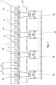
- Fig. 1 a possible system for carrying out the method according to the invention is shown.
- a transport device 2 products 4, in particular medical devices such as syringes, ampoules, vials or inhalers, are conveyed individually in a transport direction T continuously at a constant translation speed.
- the transport device 2 has individual cells 6, in each of which a product 4 is accommodated in a receptacle 7.
- the cells 6 are each identically designed.
- the cells 6 have an identical distance D from one another (see Fig. 2 ).
- the products 4 each have a lateral surface 8 in some areas, to which a marking 10 is generally applied, for example, as a label or directly printed.
- the products 4 are initially rotatably mounted in the cells 6 in a random orientation. Each product 4 will generally have a different orientation.
- the products 4 are designed as syringes, each having a product flange 12 resting on a shoulder 14 of the respective cells 6, where the product 4 is supported against its gravity. In this case, the products 4 hang vertically in the respective receptacles 7.
- the products 4 are guided in the transport direction T past a camera system 16, which in the example shown consists of four cameras 18.
- the individual cameras 18 are arranged so that they can be moved relative to one another in the transport direction T in order to ensure optimal adjustment for different products 4 or product formats. During operation, however, they remain stationary in their preset position.
- the friction element 20 is designed here as a stationary strip, which has an elastomer material on the side facing the products 4, which engages with each product 4 through friction, in this case static friction.
- the friction element 20 can be adjustable in order to be adapted to different product formats.
- the friction element 20 comes into direct contact with the outer surface 8 of the products 4 and causes a uniform rotation of the products 4 about a rotation axis 22 of each product 4, which is perpendicular to the transport direction T.
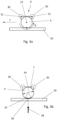
- the direction of rotation is in Fig. 3a sketched with arrow R.
- each camera 18 has an active field of view 24 in which it can record the marking 10 of the product 4.
- the active fields of view 24 of the individual cameras 18 preferably do not overlap.
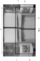
- An example of an active field of view 24 of a camera 18 in the area of the products 4 is shown in Fig. 5 by means of the inner rectangle as a section of a larger image area or maximum field of view of the camera 18.
- the system also comprises an evaluation unit 26 for the images recorded by the cameras 18 and a controller 28 to which the data is transmitted from the evaluation unit 26.
- the controller 28 can simultaneously be responsible for the operation of the transport device 2 or at least provide information about the Operation of the transport device 2.
- the controller 28 can also trigger an activation interval of each camera 18.
- each product 4 in its receptacle 7 of the corresponding cell 6 is preferably mounted on rollers 30 whose axes of rotation 31 run parallel to the axis of rotation 22 of the product 4.
- Each camera 18 detects the marking 10 only within a certain rotation angle range on both sides around a vertical zero line 36, to which the viewing direction 38 of the camera 18 is perpendicular ( Fig. 3b ).
- This angular range is identified by reference numeral 32.
- This angular range 32 depends on the diameter 34 of the product 4 and is generally 60° or less in total.
- the frequency of image capture by each camera 18 must be high enough to capture at least one image of the complete license plate 10 in this angular range.
- the arrangement of the individual cameras 18 is carried out in such a way that the correlation between the translation speed of the transport device 2, the diameter 34 of the rotationally symmetrical area of the product 4, the distance D of the cells 6 of the transport device 2, the width B of the active field of view 24 of the cameras 18 in the area of the products 4 and the distance of the cameras 18 to one another is such that a circumferential section of the product 4 captured by the active field of view 24 of each camera during the rotation of the product 4 differs from a circumferential section of the product 4 captured by the active field of view 24 of the other cameras 18 during the rotation of the product 4.
- the active fields of view 24 of the cameras 18 preferably overlap by the extent of the marking 10 in the circumferential direction of the lateral surface 8.
- the cameras 18 together cover the entire circumference of the lateral surface 8 of the product 4, regardless of the original orientation of the product 4.
- the overlap of the active fields of view 24 serves to ensure that the complete marking 10 can be read in at least one active field of view 24 of a camera 18.
- the width B of the active field of view 24 of each camera 18 in the area of the products 4 is as large as possible. At the same time, it should be ensured that only one license plate 10 can be read simultaneously in the active field of view 24 of a camera 18.
- the width B of the active field of view 24 in the area of the products 4 was chosen to be so wide that a second marking 10 of a further product 4 can already appear at the right edge of the active field of view 24, while the first marking 10 of a first product 4 is still located at the left edge of the active field of view 24.
- the marking 10 located at the right edge cannot yet be read by the camera 18 due to its rotational position relative to the latter.
- the scenario shown therefore represents a borderline situation of the maximum width B of the active field of view 24 when the camera 18 is only supposed to recognize one marking 10 in an image recording.
Landscapes
- Engineering & Computer Science (AREA)
- Physics & Mathematics (AREA)
- Electromagnetism (AREA)
- Theoretical Computer Science (AREA)
- General Physics & Mathematics (AREA)
- Health & Medical Sciences (AREA)
- Toxicology (AREA)
- Computer Vision & Pattern Recognition (AREA)
- Artificial Intelligence (AREA)
- General Health & Medical Sciences (AREA)
- Mechanical Engineering (AREA)
- Computer Networks & Wireless Communication (AREA)
- Investigating Materials By The Use Of Optical Means Adapted For Particular Applications (AREA)
- Length Measuring Devices By Optical Means (AREA)
- Specific Conveyance Elements (AREA)
- Eyeglasses (AREA)
Description
- Die vorliegende Erfindung betrifft ein Verfahren zur Identifizierung und Nachverfolgung von vereinzelt geförderten Produkten.
- Viele Produkte, insbesondere in der pharmazeutischen Industrie, sind mit optischen Kennzeichnungen (QR-Codes, Datamatrix-Code etc.) versehen, um eine eindeutige Identifizierung und Nachverfolgung des einzelnen Produkts zu ermöglichen.
- Wenn im Laufe der Förderung der Produkte diese Kennzeichnungen abgefragt werden sollen, müssen die Produkte bezüglich der jeweiligen Kamera so ausgerichtet sein, dass die Kennzeichnung der Kamera zugewandt ist oder, im Fall von Produkten ohne Vororientierung, das Produkt von verschiedenen Seiten mittels einer Kamera begutachtet wird.
-
DE 32 41 489 A1 schlägt ein Verfahren zum Markieren von transparenten Behältern mit umfangsseitigen Farbmarken vor, bei dem die Behälter in einer Lesestation mittels eines Reibrads einzeln gedreht werden. - In
WO 2013/083544 A1 wird eine Lesevorrichtung vorgestellt, in der ein Behälter mit zu lesenden, umfangsseitigen Markierungen kontinuierlich gedreht wird, während dieser ebenfalls translatorisch entlang einer Förderstrecke bewegt wird, die sich in einem Sichtbereich eines optischen Sensors befindet. -
WO 2014/031576 A1 offenbart ein Verfahren, das in ähnlicher Weise einen Träger eines Behälters samt dem Behälter entlang einer Förderstrecke translatorisch bewegt und kontinuierlich dreht, während der Träger mit dem Behälter einen Sichtbereich eines optischen Sensors durchfährt. -
WO 2018/184760 A1 zeigt eine Vorrichtung, die einen Behälter in einem Sichtbereich eines optischen Sensors mittels eines Reibrads dreht, um eine an dem Behälterumfang angebrachte Markierung auszulesen. - Der vorliegenden Erfindung liegt die Aufgabe zugrunde, eine robuste Erkennung von auf ohne Vororientierung vorliegenden Produkten aufgebrachten Kennzeichnungen während des Transports der Produkte mit möglichst geringem apparativem Aufwand zu gewährleisten.
- Diese Aufgabe wird durch die Merkmale des Anspruchs 1 gelöst.
- Erfindungsgemäß umfasst das Verfahren zur Identifizierung und Nachverfolgung von vereinzelt geförderten Produkten, insbesondere von Medizinprodukten wie Spritzen, Ampullen, Vials oder Inhalatoren, wobei die vereinzelt geförderten Produkte zumindest bereichsweise rotationssymmetrisch, insbesondere zylindrisch, ausgebildet sind und eine Mantelfläche aufweisen, auf die jeweils eine Kennzeichnung, insbesondere ein Code, aufgebracht ist, folgende Schritte:
- Fördern der Produkte mittels einer Transportvorrichtung in einer Transportrichtung, wobei die Transportvorrichtung eine Vielzahl von aufeinanderfolgenden Zellen zur Aufnahme jeweils eines Produkts aufweist, wobei jedes Produkt in der zugehörigen Zelle drehbar aufgenommen ist,
- Drehen eines jeden Produkts während des Förderns mittels eines Reibungselements, das beim Fördern der Produkte mit jedem Produkt durch Reibung, bevorzugt Haftreibung, in Eingriff gelangt, und
- Auslesen der auf die Mantelfläche eines jeden Produkts aufgebrachten Kennzeichnung mittels eines stationären Kamerasystems mit mindestens einer Kamera während des Drehens des jeweiligen Produkts.
- Das Kamerasystem weist mehrere Kameras auf, die in Transportrichtung aufeinanderfolgend und vorzugsweise in einer Linie angeordnet sind, zumindest aber eine erste und eine zweite Kamera.
- Die Korrelation zwischen der Translationsgeschwindigkeit der Transportvorrichtung, dem Durchmesser des rotationssymmetrischen Bereichs des Produkts, dem Abstand der Zellen der Transportvorrichtung, der Breite des aktiven Sichtfelds der Kameras im Bereich der Produkte und dem Abstand der Kameras wird zueinander derart eingestellt, dass sich ein vom aktiven Sichtfeld der zweiten Kamera während der Drehung des Produkts erfasster zweiter Umfangsabschnitt des Produkts von einem vom aktiven Sichtfeld der ersten Kamera während der Drehung des Produkts erfassten ersten Umfangsabschnitt des Produkts unterscheidet.
- Mit diesem Verfahren wird eine robuste Kennzeichnungserkennung von ohne Vororientierung geförderten Produkten während des Förderns gewährleistet. Allgemein im Rahmen der Erfindung werden Produkte ohne Vororientierung in der Transportvorrichtung aufgenommen, sodass die Ausrichtung der Kennzeichnung in der Zelle der Transportvorrichtung zufällig ist. Erst durch die Drehung der Produkte werden alle Abschnitte der Mantelfläche des Produkts vor dem Kamerasystem präsentiert und mindestens eine 360°-Drehung jedes Produkts vor dem Kamerasystem ist nötig, um jede Kennzeichnung sicher mit dem Kamerasystem zu erfassen.
- Aufgrund der mehreren Kameras kann ein höherer Durchsatz der Produkte und eine höhere Transportgeschwindigkeit verwirklicht werden als mit einer einzigen Kamera, weil jede einzelne Kamera nur einen Teilumfang der Mantelfläche des Produkts auf die Kennzeichnung hin überprüfen muss. In einer bevorzugten Ausgestaltung kann das Kamerasystem auch drei, vier oder noch mehr Kameras aufweisen. Die Drehung der Produkte erfolgt vorzugsweise kontinuierlich im Bereich des gesamten Kamerasystems, d.h. entlang aller vorhandenen Kameras.
- Die Wirkung des Reibungselements auf das Produkt entspricht einem mechanischen Bremsen. Aufgrund der drehbaren Lagerung des Produkts vollzieht dieses eine Drehung und rollt sich am Reibungselement ab.
- In einer bevorzugten Ausführungsform ist das Reibungselement stationär im Sinne von unbewegt angeordnet. Hierdurch wird der strukturelle Aufbau besonders einfach gestaltet. Jedes Produkt rollt sich an dem stationären Reibungselement während der Förderung ab und bietet somit dem Kamerasystem während des Drehens jeweils einen bestimmten Umfangsabschnitt der Mantelfläche zur Begutachtung an. Das Reibungselement kann auch bewegt sein und läuft dann vorzugsweise mit konstanter Geschwindigkeit in Gegenrichtung zur Transportrichtung der Produkte.
- In einer bevorzugten Ausgestaltung ist das Reibungselement eine Leiste. Ebenfalls ist die Ausgestaltung als umlaufender Riemen, drehbare Rolle oder drehbare Scheibe denkbar.
- In besonders bevorzugter Ausgestaltung weist das Reibungselement ein Elastomer-Material auf, zumindest an der den Produkten zugewandten Seite des Reibungselements. Das Elastomer wird durch die vorbeilaufenden Produkte deformiert und die Produkte werden mittels Haftreibung besonders zuverlässig in Rotationsbewegung versetzt.
- Es ist bevorzugt, dass das Angreifen des Reibungselements für das Drehen des Produkts an jedem Produkt im Bereich der Mantelfläche des Produkts erfolgt. Auf diese Weise wird eine konstante und sichere Drehung des Produkts gewährleistet.
- Für eine sichere und gleichmäßige Drehung eines jeden Produkts ohne Schlupf ist es bevorzugt, wenn der Reibungskoeffizient zwischen dem Reibungselement und dem Material des Produkts bevorzugt mindestens 0,2, mehr bevorzugt mindestens 0,3, besonders bevorzugt mindestens 0,4 beträgt. Der Reibwert wird hierbei gemäß DIN ISO 8295 aus dem Jahr 1995 ermittelt.
- Die Aufnahme jeder Zelle weist bevorzugt eine Formnut auf, mittels derer das Produkt in Position gehalten wird.
- Jedes Produkt ist in seiner Aufnahme bevorzugt gegen seine Schwerkraft abgestützt und das Drehen des Produkts erfolgt um eine Rotationsachse des Produkts. Die Rotationsachse des Produkts verläuft in der Regel senkrecht zur Transportrichtung. Zur Abstützung des Produkts in der Aufnahme gegen seine Schwerkraft kann beispielsweise ein Produktflansch dienen, der auf einer oder mehreren Schultern der Aufnahme während der gesamten Drehung des Produkts um 360° abgestützt ist. Ebenso ist es denkbar, dass ein Bodenabschnitt des Produkts auf einem Stützboden der Zelle abgestützt ist.
- Es ist jeweils bevorzugt, dass das Produkt in der Aufnahme an Rollen gelagert ist, deren Drehachse beispielsweise parallel zur Rotationsachse des Produkts ist. In besonders bevorzugter Ausgestaltung liegt die Mantelfläche des Produkts an den Rollen an. Hierdurch wird die Reibung zwischen Produkt und Zelle minimiert. Alternativ oder zusätzlich ist es denkbar, weitere Maßnahmen vorzusehen, die ein leichtes Gleiten beim Drehen des Produkts in der Zelle bewirken und den Reibungskoeffizienten zwischen Produkt und Aufnahme reduzieren. Beispielsweise kann die Schulter bzw. der Stützboden der Zelle zumindest an der dem Produkt zugewandten Seite ein hartes, glattes Material aufweisen.
- In bevorzugter Ausgestaltung erfolgt das Fördern mit gleichmäßiger Translationsgeschwindigkeit und das Drehen erfolgt mit gleichmäßiger Drehgeschwindigkeit. Auf diese Weise wird eine sichere Erfassung der Kennzeichnung durch das Kamerasystem gefördert und die Auswertung der Kameraaufnahmen wird erleichtert.
- Die Translationsgeschwindigkeit der Produkte kann prinzipiell so klein wie 1 mm pro Sekunde sein, beträgt üblicherweise aber bevorzugt mindestens 10 mm pro Sekunde, mehr bevorzugt mindestens 60 mm pro Sekunde, besonders bevorzugt mindestens 100 mm pro Sekunde.
- Der Durchmesser im rotationssymmetrischen Bereich der Produkte liegt vorzugsweise zwischen 5 und 40 mm, mehr bevorzugt zwischen 6 und 30 mm.
- Die Drehgeschwindigkeit der Produkte beträgt üblicherweise von 0,08 bis 8 Umdrehungen pro Sekunde, bevorzugt von 0,1 bis 6 Umdrehungen pro Sekunde, mehr bevorzugt von 0,5 bis 6 Umdrehungen pro Sekunde, besonders bevorzugt von 1 bis 6 Umdrehungen pro Sekunde.
- Es ist dabei bevorzugt, wenn sich die aktiven Sichtfelder der mehreren Kameras im Bereich der Produkte räumlich nicht überlagern. Dies trägt dazu bei, Doppelerfassungen einer Kennzeichnung durch mehrere Kameras auszuschließen.
- Das "aktive Sichtfeld" einer Kamera kann entweder bauartbedingt für diese Kamera bereits dem tatsächlichen Sichtfeld der Kamera entsprechen. Alternativ kann das tatsächliche Sichtfeld der Kamera mittels geeigneter Softwareeinstellungen auf das gewünschte aktive Sichtfeld eingeschränkt werden, sodass nur die Inhalte dieses Bereichs aufgenommen bzw. ausgewertet werden.
- Das aktive Sichtfeld jeder Kamera kann beispielsweise rechteckig sein. Die Breite des "aktiven Sichtfelds" jeder Kamera im Bereich der Produkte ist üblicherweise nicht größer als der jeweils gleiche Abstand zwischen zwei Zellen der Transportvorrichtung, bevorzugt zwischen 10 und 60 % kleiner, mehr bevorzugt zwischen 20 und 40 % kleiner. Hierdurch wird sichergestellt, dass zu jedem Zeitpunkt maximal eine Kennzeichnung eines Produkts im aktiven Sichtfeld einer Kamera identifizierbar ist, aber keine weitere Kennzeichnung eines zweiten Produkts. Alternativ ist es auch möglich, dass mittels einer Kamera gleichzeitig zwei Kennzeichnungen von aufeinanderfolgenden Produkten ausgelesen werden.
- Die Höhe des aktiven Sichtfelds jeder Kamera ist aus Sicherheitsgründen in der Regel etwas größer zu wählen als die Höhe der Kennzeichnung, beispielsweise zwischen 30 % und 150 % größer.
- Die Erkennung einer Kennzeichnung auf der Mantelfläche der Produkte durch eine Kamera wird üblicherweise bei einer Anordnung der Kennzeichnung in einem Drehwinkelbereich des Produkts von zwischen +/- 30°, manchmal auch erst in einem Bereich von zwischen +/- 20° oder von zwischen +/- 15° relativ zu einer zentralen Nulllinie möglich sein. Die zentrale Nulllinie entspricht dabei der Linie auf dem Produkt, auf welche die Kamera jeweils zu einem bestimmten Zeitpunkt senkrecht blickt.
- Prinzipiell ist es im Rahmen der Erfindung möglich, das aktive Sichtfeld jeder Kamera durchgängig aktiv zu belassen und somit ständig Bilder in diesem Sichtfeld aufzunehmen. Vorteilhaft ist es allerdings, wenn jede Kamera nur zeitweise aktiviert wird. Auf diese Weise entfällt die Bildaufnahme zu irrelevanten Zeitpunkten.
- In diesen Fällen ist ein Zeitintervall der Bildaufnahme einer Kamera üblicherweise nicht länger als die Dauer, in der sich die Transportvorrichtung um den Abstand zwischen zwei Zellen vorwärtsbewegt, vorzugsweise um 1 bis 30 % kürzer, mehr bevorzugt um 2 bis 25 % kürzer.
- Die Aktivierungszeit jeder Kamera stimmt dabei vorzugsweise im Wesentlichen mit dem Zeitraum überein, in dem sich ein Produkt im aktiven Sichtfeld der Kamera befindet. Die Aktivierungszeit jeder Kamera wird vorzugsweise extern über eine Steuerung, beispielsweise über eine speicherprogrammierbare Steuerung des Gesamtsystems, vorgegeben, die den jeweiligen Ort jedes Produkts kennt.
- Bei Verwendung mehrerer Kameras ist es grundsätzlich bevorzugt, dass alle stromabwärtigen Kameras für den Zeitraum des Durchlaufs eines bestimmten Produkts deaktiviert werden, sobald für dieses Produkt eine Kennzeichnung von einer der stromaufwärtigen Kameras erkannt wurde. Wenn von einer bestimmten Kamera die Kennzeichnung erfasst wurde, wird außerdem auch diese Kamera vorzugsweise deaktiviert, bis ein neues Produkt in deren aktives Sichtfeld gelangt oder das Sichtfeld wieder für das nächste Produkt aktiviert wird. Unter "deaktiviert" wird hierbei verstanden, dass entweder die Bildaufnahme der Kamera abgeschaltet wird oder dass die aufgenommenen Bilddaten nicht ausgewertet werden.
- Bei der Einstellung der Korrelation zwischen der Translationsgeschwindigkeit der Transportvorrichtung, dem Durchmesser des rotationssymmetrischen Bereichs des Produkts, dem Abstand der Zellen der Transportvorrichtung, der Breite des aktiven Sichtfelds der Kameras im Bereich der Produkte und dem Abstand der Kameras zueinander muss auch die Aktivierungszeit jeder Kamera entsprechend mit den übrigen Parametern abgestimmt sein, wenn die Kameras nicht durchgängig Bilder aufnehmen.
- Dabei ist es bevorzugt, wenn sich der erste und der zweite Umfangsabschnitt mindestens um eine Erstreckung der Kennzeichnung in Umfangsrichtung des rotationssymmetrischen Bereichs überlagern. Wenn genau zwei Kameras vorliegen, ist eine entsprechende Überlagerung an beiden Rändern der Umfangsabschnitte sinnvoll.
- Wenn zusätzlich eine dritte Kamera vorliegt, soll sich der vom aktiven Sichtfeld der dritten Kamera während der Drehung des Produkts erfasste dritte Umfangsabschnitt des Produkts vom ersten und zweiten Umfangsabschnitt des Produkts unterscheiden. Wenn eine vierte Kamera vorliegt, soll sich der vom aktiven Sichtfeld der vierten Kamera während der Drehung des Produkts erfasste vierte Umfangsabschnitt des Produkts vom ersten, zweiten und dritten Umfangsabschnitt des Produkts unterscheiden. Für gegebenenfalls vorhandene weitere Kameras gilt entsprechendes. Es ist jeweils bevorzugt, wenn in diesen Fällen sich jeweils einer der Umfangsabschnitte, der von einer der Kameras abgedeckt wird, sich mindestens um die Abrollstrecke der Kennzeichnung in Umfangsrichtung des rotationssymmetrischen Bereichs mit zwei anderen Umfangsabschnitten überlagert. Insgesamt decken die mehreren Kameras somit in Summe den gesamten Umfang der Mantelfläche des Produkts ab, wobei in den Überschneidungsbereichen jeweils Überlappungen vorliegen. Auf diese Weise kann bei Gewährleistung eines sicheren Betriebs ein maximaler Durchsatz erzielt werden.
- Vorzugsweise liegt eine Auswertefrequenz der mindestens einen Kamera im Bereich von 20 bis 60 Bildern pro Sekunde, bevorzugt im Bereich von 30 bis 50 Bildern pro Sekunde.
- Allgemein im Rahmen der Erfindung ist die Kennzeichnung vorzugsweise ein 2D-Code, insbesondere ein QR-Code oder ein Datamatrix-Code. Es sind aber auch andere handelsübliche Kennzeichnungen denkbar, die optisch erkannt werden können.
- Die Kennzeichnung ist üblicherweise entlang der Mantelfläche des Produkts angeordnet und zeigt daher eine Krümmung in Umfangsrichtung der Mantelfläche.
- Die Kameras des Kamerasystems sind vorzugsweise digitale Bildaufnahmegeräte bzw. Codeleser.
- Üblicherweise ist der vorgegebene Abstand zwischen aufeinanderfolgenden Zellen der Transportvorrichtung im Bereich von 20 mm bis 100 mm, mehr bevorzugt im Bereich von 20 mm bis 65 mm.
- Der Abstand zwischen Kamera und Produkt beträgt in der Regel zwischen 50 mm und 120 mm, bevorzugt zwischen 60 mm und 80 mm.
- Der Abstand zweier aufeinanderfolgender Kameras zueinander beträgt in der Regel zwischen 50 mm und 150 mm, bevorzugt zwischen 70 mm und 100 mm.
- Die Auswertung und/oder Dekodierung der aufgenommenen Bilder und/oder Codes kann entweder in einer integrierten Auswerteeinheit im Kamerasystem selbst erfolgen oder in einer externen Auswerteeinheit. Diese kann beispielsweise Teil der Maschinensteuerung sein oder Daten an diese liefern.
- Die Zuordnung von Produkt und Kennzeichnung erfolgt üblicherweise auf einem übergeordneten System, zum Beispiel einer speicherprogrammierbaren Steuerung.
- Insbesondere kann der Dateninhalt des Codes nach erfolgter Dekodierung in einem Schieberegister dem Produkt zugeordnet werden und/oder an eine Steuerung übermittelt werden und/oder an eine Datenbank übermittelt werden.
- Im Folgenden werden spezielle Ausführungsformen der Erfindung unter Bezugnahme auf die Zeichnungen beschrieben.
- Fig. 1
- ist eine Perspektivansicht einer Vorrichtung zur Durchführung des erfindungsgemäßen Verfahrens;
- Fig. 2
- ist eine Draufsicht auf die Vorrichtung aus
Fig. 1 ; - Fig. 3a
- ist eine Querschnittsansicht durch eine Zelle der Transportvorrichtung mit aufgenommenem Produkt;
- Fig. 3b
- entspricht
Fig. 3a , enthält aber zusätzliche geometrische Angaben; und - Fig. 4
- zeigt eine mögliche Bildaufnahme einer Kamera im Rahmen des erfindungsgemäßen Verfahrens.
- In
Fig. 1 ist ein mögliches System zur Durchführung des erfindungsgemäßen Verfahrens dargestellt. - In einer Transportvorrichtung 2 werden Produkte 4, insbesondere Medizinprodukte wie Spritzen, Ampullen, Vials oder Inhalatoren, vereinzelt in einer Transportrichtung T kontinuierlich mit gleichbleibender Translationsgeschwindigkeit gefördert. Die Transportvorrichtung 2 weist einzelne Zellen 6 auf, in denen jeweils ein Produkt 4 in einer Aufnahme 7 aufgenommen ist. Die Zellen 6 sind jeweils identisch ausgebildet. Die Zellen 6 haben einen identischen Abstand D zueinander (siehe
Fig. 2 ). Die Produkte 4 weisen jeweils bereichsweise eine Mantelfläche 8 auf, auf die allgemein jeweils eine Kennzeichnung 10 aufgebracht ist, beispielsweise als Etikett aufgeklebt oder direkt aufgedruckt ist. - Die Produkte 4 sind in den Zellen 6 anfangs in willkürlicher Ausrichtung drehbar aufgenommen. Jedes Produkt 4 wird dabei in der Regel eine andere Orientierung aufweisen. Im vorliegenden Fall sind die Produkte 4 als Spritzen ausgebildet, die einen Produktflansch 12 aufweisen, der auf einer Schulter 14 der jeweiligen Zellen 6 aufliegt, wo das Produkt 4 gegen seine Schwerkraft abgestützt ist. Die Produkte 4 hängen in diesem Fall vertikal in den jeweiligen Aufnahmen 7.
- Die Produkte 4 werden in Transportrichtung T an einem Kamerasystem 16 vorbeigeführt, das im dargestellten Beispielsfall aus vier Kameras 18 besteht. Die einzelnen Kameras 18 sind in Transportrichtung T zueinander verschiebbar angeordnet, um für unterschiedliche Produkte 4 bzw. Produktformate eine optimale Einstellung zu gewährleisten. Während des Betriebs verbleiben sie aber stationär in ihrer voreingestellten Position.
- Während der Translationsbewegung der Produkte 4 werden die Produkte 4 in Kontakt mit einem Reibungselement 20 gebracht. Das Reibungselement 20 ist hier als stationäre Leiste ausgebildet, die auf der den Produkten 4 zugewandten Seite ein Elastomer-Material aufweist, das mit jedem Produkt 4 durch Reibung, hier Haftreibung, in Eingriff gelangt. Das Reibungselement 20 kann verstellbar sein, um an verschiedene Produktformate angepasst zu werden. Das Reibungselement 20 kommt direkt mit der Mantelfläche 8 der Produkte 4 in Kontakt und bewirkt eine gleichmäßige Drehung der Produkte 4 um eine Rotationsachse 22 eines jeden Produkts 4, die senkrecht zur Transportrichtung T ist. Die Drehrichtung ist in
Fig. 3a mit Pfeil R skizziert. - Wie aus
Fig. 2 hervorgeht, besitzt jede Kamera 18 ein aktives Sichtfeld 24, in dem sie die Kennzeichnung 10 des Produkts 4 aufnehmen kann. Die aktiven Sichtfelder 24 der einzelnen Kameras 18 überlappen sich vorzugsweise nicht. Ein Beispiel eines aktiven Sichtfelds 24 einer Kamera 18 im Bereich der Produkte 4 ist in Fig. 5 mittels des inneren Rechtecks als Ausschnitt eines größeren Bildbereichs bzw. maximalen Sichtfelds der Kamera 18 dargestellt. - Wie aus
Fig. 1 hervorgeht, umfasst das System zudem eine Auswerteeinheit 26 für die von den Kameras 18 aufgenommenen Bilder sowie eine Steuerung 28, an welche die Daten von der Auswerteeinheit 26 übermittelt werden. Die Steuerung 28 kann gleichzeitig für den Betrieb der Transportvorrichtung 2 zuständig sein oder zumindest Informationen über den Betrieb der Transportvorrichtung 2 erhalten. Die Steuerung 28 kann außerdem ein Aktivierungsintervall einer jeden Kamera 18 triggern. - Während die einzelnen Produkte 4 am Reibungselement 20 ablaufen und in Drehung versetzt werden, wird die auf die Mantelfläche 8 eines jeden Produkts 4 aufgebrachte Kennzeichnung 10 mittels der Kameras 18 des Kamerasystems 16 ausgelesen. Wie aus
Fig. 3a und 3b hervorgeht, ist jedes Produkt 4 in seiner Aufnahme 7 der entsprechenden Zelle 6 dabei vorzugsweise an Rollen 30 gelagert, deren Drehachsen 31 parallel zur Rotationsachse 22 des Produkts 4 verlaufen. - Jede Kamera 18 erkennt die Kennzeichnung 10 lediglich innerhalb eines bestimmten Drehwinkelbereichs beidseits um eine vertikale Nulllinie 36 herum, auf die die Blickrichtung 38 der Kamera 18 senkrecht trifft (
Fig. 3b ). InFig. 3b ist dieser Winkelbereich mit Bezugszeichen 32 gekennzeichnet. Dieser Winkelbereich 32 ist abhängig vom Durchmesser 34 des Produkts 4 und beträgt in der Regel insgesamt 60° oder weniger. Die Frequenz der Bildaufnahme durch jede Kamera 18 muss so hoch sein, dass mindestens eine Aufnahme des vollständigen Kennzeichens 10 in diesem Winkelbereich erfolgt. - Die Anordnung der einzelnen Kameras 18 wird dabei so vorgenommen, dass die Korrelation zwischen der Translationsgeschwindigkeit der Transportvorrichtung 2, dem Durchmesser 34 des rotationssymmetrischen Bereichs des Produkts 4, dem Abstand D der Zellen 6 der Transportvorrichtung 2, der Breite B des aktiven Sichtfelds 24 der Kameras 18 im Bereich der Produkte 4 und dem Abstand der Kameras 18 zueinander derart ist, dass sich ein vom aktiven Sichtfeld 24 einer jeden Kamera während der Drehung des Produkts 4 erfasster Umfangsabschnitt des Produkts 4 von einem vom aktiven Sichtfeld 24 der anderen Kameras 18 während der Drehung des Produkts 4 erfassten Umfangsabschnitt des Produkts 4 unterscheidet. Die aktiven Sichtfelder 24 der Kameras 18 überlappen sich dabei jeweils vorzugsweise um die Erstreckung der Kennzeichnung 10 in Umfangsrichtung der Mantelfläche 8. Somit decken die Kameras 18 zusammen den gesamten Umfang der Mantelfläche 8 des Produkts 4 ab, unabhängig von der ursprünglichen Orientierung des Produkts 4. Die Überlappung der aktiven Sichtfelder 24 dient zur Sicherstellung, dass die komplette Kennzeichnung 10 in wenigstens einem aktiven Sichtfeld 24 einer Kamera 18 ausgelesen werden kann.
- Aus Effizienzgründen ist es bevorzugt, wenn die Breite B des aktiven Sichtfelds 24 einer jeden Kamera 18 im Bereich der Produkte 4 möglichst groß ist. Gleichzeitig soll sichergestellt sein, dass im aktiven Sichtfeld 24 einer Kamera 18 lediglich ein Kennzeichen 10 gleichzeitig ausgelesen werden kann.
- Wie aus der Aufnahme in
Fig. 4 zu sehen ist, wurde im dargestellten Beispielsfall die Breite B des aktiven Sichtfelds 24 im Bereich der Produkte 4 so breit gewählt, dass bereits eine zweite Kennzeichnung 10 eines weiteren Produkts 4 am rechten Rand des aktiven Sichtfelds 24 erscheinen kann, während die erste Kennzeichnung 10 eines ersten Produkts 4 sich noch am linken Rand des aktiven Sichtfelds 24 befindet. Jedoch ist die im rechten Rand befindliche Kennzeichnung 10 aufgrund ihrer Drehlage relativ zur Kamera 18 von dieser gerade noch nicht auslesbar. Das dargestellte Szenario stellt also eine Grenzsituation der maximalen Breite B des aktiven Sichtfelds 24 dar, wenn die Kamera 18 lediglich eine Kennzeichnung 10 in einer Bildaufnahme erkennen soll. - In der Regel wird man aufgrund des gewünschten hohen Durchsatzes zwischen zwei und vier Kameras 18 benötigen.
Claims (13)
- Verfahren zur Identifizierung und Nachverfolgung von vereinzelt geförderten Produkten (4), insbesondere von Medizinprodukten wie Spritzen, Ampullen, Vials oder Inhalatoren, wobei die vereinzelt geförderten Produkte (4) zumindest bereichsweise rotationssymmetrisch, insbesondere zylindrisch, ausgebildet sind und eine Mantelfläche (8) aufweisen, auf die jeweils eine Kennzeichnung (10) aufgebracht ist, mit folgenden Schritten:Fördern der Produkte (4) mittels einer Transportvorrichtung (2) in einer Transportrichtung (T), wobei die Transportvorrichtung (2) eine Vielzahl von aufeinanderfolgenden Zellen (6) zur Aufnahme jeweils eines Produkts (4) aufweist, wobei jedes Produkt (4) in der zugehörigen Zelle (6) drehbar aufgenommen ist,Drehen eines jeden Produkts (4) während des Förderns mittels eines Reibungselements (20), das beim Fördern der Produkte (4) mit jedem Produkt (4) durch Reibung in Eingriff gelangt,dadurch gekennzeichnet, dass das Verfahren den Schritt aufweist:Auslesen der auf die Mantelfläche (8) eines jeden Produkts (4) aufgebrachten Kennzeichnung (10) mittels eines stationären Kamerasystems (16) mit mindestens einer Kamera (18) während des Drehens des jeweiligen Produkts (4),wobei das Kamerasystem (16) mehrere Kameras (18), zumindest aber eine erste und eine zweite Kamera (18) aufweist, die in Transportrichtung (T) aufeinanderfolgend angeordnet sind, undwobei die Korrelation zwischen der Translationsgeschwindigkeit der Transportvorrichtung (2), einem Durchmesser (34) des rotationssymmetrischen Bereichs des Produkts (4), einem Abstand (D) der Zellen (6) der Transportvorrichtung (2), einer Breite (B) eines aktiven Sichtfelds (24) der Kameras (18) im Bereich der Produkte (4) und einem Abstand der Kameras (18) zueinander derart eingestellt wird, dass sich ein vom aktiven Sichtfeld (24) der zweiten Kamera (18) während der Drehung des Produkts (4) erfasster zweiter Umfangsabschnitt des Produkts (4) von einem vom aktiven Sichtfeld (24) der ersten Kamera (18) während der Drehung des Produkts (4) erfassten ersten Umfangsabschnitt des Produkts (4) unterscheidet.
- Verfahren nach Anspruch 1, dadurch gekennzeichnet, dass das Reibungselement (20) stationär ist.
- Verfahren nach Anspruch 2, dadurch gekennzeichnet, dass das Reibungselement (20) eine Leiste ist.
- Verfahren nach einem der vorangehenden Ansprüche, dadurch gekennzeichnet, dass das Reibungselement (20) auf der den Produkten (4) zugewandten Seite ein Elastomer-Material aufweist.
- Verfahren nach einem der vorangehenden Ansprüche, dadurch gekennzeichnet, dass jedes Produkt (4) in einer Aufnahme (7) der Zelle (6) gegen seine Schwerkraft abgestützt ist und das Drehen des Produkts (4) um eine Rotationsachse (22) des Produkts (4) erfolgt, die senkrecht zur Transportrichtung (T) ist.
- Verfahren nach einem der vorangehenden Ansprüche, dadurch gekennzeichnet, dass jedes Produkt (4) in der Aufnahme (7) der Zelle (6) an Rollen (30) gelagert ist, deren Drehachse (31) parallel zur Rotationsachse (22) des Produkts (4) ist.
- Verfahren nach einem der vorangehenden Ansprüche, dadurch gekennzeichnet, dass das Fördern mit gleichmäßiger Translationsgeschwindigkeit erfolgt und das Drehen mit gleichmäßiger Drehgeschwindigkeit erfolgt.
- Verfahren nach einem der vorangehenden Ansprüche, dadurch gekennzeichnet, dass sich die aktiven Sichtfelder (24) der mehreren Kameras (18) im Bereich der Produkte (4) räumlich nicht überlagern.
- Verfahren nach einem der vorangehenden Ansprüche, dadurch gekennzeichnet, dass sich der erste und der zweite Umfangsabschnitt mindestens um eine Erstreckung der Kennzeichnung (10) in Umfangsrichtung des rotationssymmetrischen Bereichs des Produkts (4) überlappen.
- Verfahren nach einem der vorangehenden Ansprüche, dadurch gekennzeichnet, dass eine Breite (B) des aktiven Sichtfelds (24) der mindestens einen Kamera (18) im Bereich der Produkte (4) nicht größer als der Abstand (D) zwischen zwei Zellen (6) der Transportvorrichtung (2) ist.
- Verfahren nach einem der vorangehenden Ansprüche, dadurch gekennzeichnet, dass eine Bildaufnahmefrequenz der mindestens einen Kamera (18) im Bereich von 20 bis 60 Bildern pro Sekunde liegt.
- Verfahren nach einem der vorangehenden Ansprüche, dadurch gekennzeichnet, dass ein Zeitintervall der Bildaufnahme der mindestens einen Kamera (18) nicht länger als die Dauer ist, in der sich die Transportvorrichtung (2) um den Abstand (D) zwischen zwei Zellen (6) vorwärtsbewegt.
- Verfahren nach einem der vorangehenden Ansprüche, dadurch gekennzeichnet, dass die Translationsgeschwindigkeit der Transportvorrichtung (2) mindestens 10 mm pro Sekunde beträgt.
Priority Applications (4)
| Application Number | Priority Date | Filing Date | Title |
|---|---|---|---|
| EP22166717.3A EP4258159B1 (de) | 2022-04-05 | 2022-04-05 | Verfahren zur identifizierung und nachverfolgung von vereinzelt geförderten produkten |
| KR1020230042277A KR102799635B1 (ko) | 2022-04-05 | 2023-03-30 | 하나씩 전달된 제품을 식별하고 추적하기 위한 방법 |
| US18/131,096 US20230312264A1 (en) | 2022-04-05 | 2023-04-05 | Method for identifying and tracking singly conveyed products |
| CN202310370174.6A CN116891115A (zh) | 2022-04-05 | 2023-04-06 | 识别及追踪单独传送的产品的方法 |
Applications Claiming Priority (1)
| Application Number | Priority Date | Filing Date | Title |
|---|---|---|---|
| EP22166717.3A EP4258159B1 (de) | 2022-04-05 | 2022-04-05 | Verfahren zur identifizierung und nachverfolgung von vereinzelt geförderten produkten |
Publications (3)
| Publication Number | Publication Date |
|---|---|
| EP4258159A1 EP4258159A1 (de) | 2023-10-11 |
| EP4258159C0 EP4258159C0 (de) | 2025-06-04 |
| EP4258159B1 true EP4258159B1 (de) | 2025-06-04 |
Family
ID=81454798
Family Applications (1)
| Application Number | Title | Priority Date | Filing Date |
|---|---|---|---|
| EP22166717.3A Active EP4258159B1 (de) | 2022-04-05 | 2022-04-05 | Verfahren zur identifizierung und nachverfolgung von vereinzelt geförderten produkten |
Country Status (4)
| Country | Link |
|---|---|
| US (1) | US20230312264A1 (de) |
| EP (1) | EP4258159B1 (de) |
| KR (1) | KR102799635B1 (de) |
| CN (1) | CN116891115A (de) |
Families Citing this family (2)
| Publication number | Priority date | Publication date | Assignee | Title |
|---|---|---|---|---|
| DE102024115245A1 (de) * | 2024-05-31 | 2025-12-04 | Körber Pharma Inspection Gmbh | Inspektionsvorrichtung zur Inspektion von pharmazeutischen Produkten und Verfahren zur Inspektion von pharmazeutischen Produkten |
| CN119503263A (zh) * | 2024-11-04 | 2025-02-25 | 广州慧翼智能科技有限公司 | 一种医用针管智能采集系统及方法 |
Family Cites Families (14)
| Publication number | Priority date | Publication date | Assignee | Title |
|---|---|---|---|---|
| US2979746A (en) * | 1957-05-03 | 1961-04-18 | Seymour Foods Inc | Egg washing machine |
| US3685636A (en) * | 1970-06-22 | 1972-08-22 | Enrico Putin | Conveyor rollers |
| DE3241489A1 (de) * | 1982-11-10 | 1984-05-10 | Dirk H Dickfeld | Verfahren zur markierung und identifizierung von durchsichtigen behaeltern fuer fluessige arzneimittel u.dgl. |
| US5058724A (en) * | 1990-11-08 | 1991-10-22 | Hinton Gaylen R | Apparatus and method for orienting articles and containers |
| DE19605133C2 (de) * | 1996-02-13 | 2000-06-15 | Krones Ag | Inspektionsmaschine für Gefäße |
| FR2764704B1 (fr) * | 1997-06-16 | 1999-08-20 | Stago Diagnostica | Dispositif pour la lecture automatique d'un code d'identification porte par des recipients tubulaires |
| EP2788127B1 (de) * | 2011-12-05 | 2015-09-09 | Vesdo Ltd. | Auslesevorrichtung zum auslesen maschinenlesbarer markierungen auf behältern |
| US9952241B2 (en) * | 2012-08-20 | 2018-04-24 | Siemens Healthcare Diagnostics Inc. | Methods and apparatus for ascertaining specimen and/or sample container characteristics while in transit |
| EA201992122A1 (ru) * | 2017-05-04 | 2020-02-04 | Сикпа Холдинг Са | Устройство и способ считывания метки, напечатанной на контейнерах, движущихся по конвейеру |
| DE102018102055A1 (de) * | 2018-01-30 | 2019-08-01 | Krones Ag | Vorrichtung und Verfahren zur Überprüfung der Etikettier- und/oder Druckgenauigkeit |
| CN208135384U (zh) * | 2018-02-21 | 2018-11-23 | 重庆环视高科技有限公司 | 一种药瓶整序输送装置 |
| BR112020026127A2 (pt) * | 2018-06-20 | 2021-03-16 | Amcor Rigid Packaging Usa, Llc | Codificação de garrafa de pet reutilizável para a rastreabilidade do ciclo de vida de um recipiente |
| CN209085712U (zh) * | 2019-05-29 | 2019-07-09 | 赛默飞世尔(上海)仪器有限公司 | 用于监测蒸发器的样品收集瓶中的液位的系统 |
| US20220414861A1 (en) * | 2019-12-23 | 2022-12-29 | Boon Logic Inc. | Product inspection system and method |
-
2022
- 2022-04-05 EP EP22166717.3A patent/EP4258159B1/de active Active
-
2023
- 2023-03-30 KR KR1020230042277A patent/KR102799635B1/ko active Active
- 2023-04-05 US US18/131,096 patent/US20230312264A1/en active Pending
- 2023-04-06 CN CN202310370174.6A patent/CN116891115A/zh active Pending
Also Published As
| Publication number | Publication date |
|---|---|
| EP4258159C0 (de) | 2025-06-04 |
| US20230312264A1 (en) | 2023-10-05 |
| KR102799635B1 (ko) | 2025-04-23 |
| CN116891115A (zh) | 2023-10-17 |
| EP4258159A1 (de) | 2023-10-11 |
| KR20230143573A (ko) | 2023-10-12 |
Similar Documents
| Publication | Publication Date | Title |
|---|---|---|
| EP0338376B1 (de) | Verfahren zum optischen Abtasten von Markierungen auf Gegenständen und Vorrichtung zu seiner Durchführung | |
| EP4258159B1 (de) | Verfahren zur identifizierung und nachverfolgung von vereinzelt geförderten produkten | |
| EP3601118B1 (de) | Produktionssystem mit ftf zum automatisch abgeben von behältern an entnahmeregalen | |
| EP2751744B1 (de) | Wendevorrichtung für identifikationsgegenstände | |
| EP3030492B1 (de) | Etikettiereinrichtung, etikettiersystem und verfahren zum bestücken eines produkts mit einem etikett | |
| EP3501995A1 (de) | Verfahren zur steuerung der parameter eines umreifungssystems | |
| EP0682991A2 (de) | Sortierautomat zur Sortierung bzw. Klassifikation von Kleinprodukten der pharmazeutischen und der Süsswarenindustrie nach Form und Farbe | |
| EP0633207A1 (de) | Transportsystem zum Transport von Proben zu unterschiedlichen Behandlungseinrichtungen | |
| EP3836001B1 (de) | Lesen einer vielzahl von codes | |
| EP1714786B1 (de) | Vorrichtung zur Inspektion von Druckerzeugnissen | |
| EP3081927A1 (de) | Vorrichtung zum verpacken von einzelnen medikamentenportionen und verfahren zu deren betrieb | |
| EP2499501B1 (de) | Vorrichtung zur entnahme von behältern und verpackungsanlage | |
| EP1431707A1 (de) | Verfahren und Vorrichtung zur Erfassung von auf einem Fördermittel bewegten Objekten mittels eines optoelektronischen Sensors | |
| EP0582964B1 (de) | Verfahren und Vorrichtung zur Datenerfassung von auf Förderbahnen transportierten Gegenständen, insbesondere von Paketen | |
| EP2485897B1 (de) | System, aufweisend mindestens eine druckeinheit einer druckmaschine und mindestens einen transportwagen | |
| EP2105891A1 (de) | Leergut-Rücknahmeautomat | |
| DE102005054122B4 (de) | Verfahren zum Betrieb eines Qualitätskontrollsystems für eine Bogenrotationsdruckmaschine | |
| EP2474956B1 (de) | Transporteinheit und Verfahren zum Betrieb derselben | |
| DE102014103331B4 (de) | Steuerungsvorrichtung und -verfahren für eine Umreifungsmaschine | |
| DE102015117601A1 (de) | Prüfvorrichtung zum Prüfen von Münzrohlingen | |
| DE102014103332B4 (de) | System und Verfahren zur Steuerung von Umreifungsmitteln | |
| WO2024227512A1 (de) | Vorrichtung und verfahren zur bearbeitung von lebensmittelprodukten | |
| DE202019106914U1 (de) | Lesen einer Vielzahl von Codes | |
| DE202005014456U1 (de) | Vorrichtung zum Ausrichten von Behältern | |
| EP4492047A1 (de) | Vorrichtung zum herstellen von gefüllten folienbeuteln |
Legal Events
| Date | Code | Title | Description |
|---|---|---|---|
| PUAI | Public reference made under article 153(3) epc to a published international application that has entered the european phase |
Free format text: ORIGINAL CODE: 0009012 |
|
| STAA | Information on the status of an ep patent application or granted ep patent |
Free format text: STATUS: THE APPLICATION HAS BEEN PUBLISHED |
|
| AK | Designated contracting states |
Kind code of ref document: A1 Designated state(s): AL AT BE BG CH CY CZ DE DK EE ES FI FR GB GR HR HU IE IS IT LI LT LU LV MC MK MT NL NO PL PT RO RS SE SI SK SM TR |
|
| P01 | Opt-out of the competence of the unified patent court (upc) registered |
Effective date: 20231012 |
|
| STAA | Information on the status of an ep patent application or granted ep patent |
Free format text: STATUS: REQUEST FOR EXAMINATION WAS MADE |
|
| 17P | Request for examination filed |
Effective date: 20240404 |
|
| RBV | Designated contracting states (corrected) |
Designated state(s): AL AT BE BG CH CY CZ DE DK EE ES FI FR GB GR HR HU IE IS IT LI LT LU LV MC MK MT NL NO PL PT RO RS SE SI SK SM TR |
|
| GRAP | Despatch of communication of intention to grant a patent |
Free format text: ORIGINAL CODE: EPIDOSNIGR1 |
|
| STAA | Information on the status of an ep patent application or granted ep patent |
Free format text: STATUS: GRANT OF PATENT IS INTENDED |
|
| GRAS | Grant fee paid |
Free format text: ORIGINAL CODE: EPIDOSNIGR3 |
|
| GRAA | (expected) grant |
Free format text: ORIGINAL CODE: 0009210 |
|
| STAA | Information on the status of an ep patent application or granted ep patent |
Free format text: STATUS: THE PATENT HAS BEEN GRANTED |
|
| INTG | Intention to grant announced |
Effective date: 20250403 |
|
| AK | Designated contracting states |
Kind code of ref document: B1 Designated state(s): AL AT BE BG CH CY CZ DE DK EE ES FI FR GB GR HR HU IE IS IT LI LT LU LV MC MK MT NL NO PL PT RO RS SE SI SK SM TR |
|
| REG | Reference to a national code |
Ref country code: GB Ref legal event code: FG4D Free format text: NOT ENGLISH |
|
| REG | Reference to a national code |
Ref country code: CH Ref legal event code: EP |
|
| REG | Reference to a national code |
Ref country code: IE Ref legal event code: FG4D Free format text: LANGUAGE OF EP DOCUMENT: GERMAN |
|
| U01 | Request for unitary effect filed |
Effective date: 20250604 |
|
| U07 | Unitary effect registered |
Designated state(s): AT BE BG DE DK EE FI FR IT LT LU LV MT NL PT RO SE SI Effective date: 20250611 |
|
| P04 | Withdrawal of opt-out of the competence of the unified patent court (upc) registered |
Free format text: CASE NUMBER: APP_26969/2025 Effective date: 20250606 |
|
| PG25 | Lapsed in a contracting state [announced via postgrant information from national office to epo] |
Ref country code: ES Free format text: LAPSE BECAUSE OF FAILURE TO SUBMIT A TRANSLATION OF THE DESCRIPTION OR TO PAY THE FEE WITHIN THE PRESCRIBED TIME-LIMIT Effective date: 20250604 |
|
| PG25 | Lapsed in a contracting state [announced via postgrant information from national office to epo] |
Ref country code: GR Free format text: LAPSE BECAUSE OF FAILURE TO SUBMIT A TRANSLATION OF THE DESCRIPTION OR TO PAY THE FEE WITHIN THE PRESCRIBED TIME-LIMIT Effective date: 20250905 Ref country code: NO Free format text: LAPSE BECAUSE OF FAILURE TO SUBMIT A TRANSLATION OF THE DESCRIPTION OR TO PAY THE FEE WITHIN THE PRESCRIBED TIME-LIMIT Effective date: 20250904 |
|
| PG25 | Lapsed in a contracting state [announced via postgrant information from national office to epo] |
Ref country code: PL Free format text: LAPSE BECAUSE OF FAILURE TO SUBMIT A TRANSLATION OF THE DESCRIPTION OR TO PAY THE FEE WITHIN THE PRESCRIBED TIME-LIMIT Effective date: 20250604 |
|
| PG25 | Lapsed in a contracting state [announced via postgrant information from national office to epo] |
Ref country code: HR Free format text: LAPSE BECAUSE OF FAILURE TO SUBMIT A TRANSLATION OF THE DESCRIPTION OR TO PAY THE FEE WITHIN THE PRESCRIBED TIME-LIMIT Effective date: 20250604 |
|
| PG25 | Lapsed in a contracting state [announced via postgrant information from national office to epo] |
Ref country code: RS Free format text: LAPSE BECAUSE OF FAILURE TO SUBMIT A TRANSLATION OF THE DESCRIPTION OR TO PAY THE FEE WITHIN THE PRESCRIBED TIME-LIMIT Effective date: 20250904 |