EP4257911B1 - Wärmeaustauschmodul - Google Patents
Wärmeaustauschmodul Download PDFInfo
- Publication number
- EP4257911B1 EP4257911B1 EP22166908.8A EP22166908A EP4257911B1 EP 4257911 B1 EP4257911 B1 EP 4257911B1 EP 22166908 A EP22166908 A EP 22166908A EP 4257911 B1 EP4257911 B1 EP 4257911B1
- Authority
- EP
- European Patent Office
- Prior art keywords
- heat exchange
- tubes
- exchange module
- channels
- substrate
- Prior art date
- Legal status (The legal status is an assumption and is not a legal conclusion. Google has not performed a legal analysis and makes no representation as to the accuracy of the status listed.)
- Active
Links
Images


Classifications
-
- F—MECHANICAL ENGINEERING; LIGHTING; HEATING; WEAPONS; BLASTING
- F01—MACHINES OR ENGINES IN GENERAL; ENGINE PLANTS IN GENERAL; STEAM ENGINES
- F01N—GAS-FLOW SILENCERS OR EXHAUST APPARATUS FOR MACHINES OR ENGINES IN GENERAL; GAS-FLOW SILENCERS OR EXHAUST APPARATUS FOR INTERNAL-COMBUSTION ENGINES
- F01N3/00—Exhaust or silencing apparatus having means for purifying, rendering innocuous, or otherwise treating exhaust
- F01N3/02—Exhaust or silencing apparatus having means for purifying, rendering innocuous, or otherwise treating exhaust for cooling, or for removing solid constituents of, exhaust
- F01N3/0205—Exhaust or silencing apparatus having means for purifying, rendering innocuous, or otherwise treating exhaust for cooling, or for removing solid constituents of, exhaust using heat exchangers
-
- F—MECHANICAL ENGINEERING; LIGHTING; HEATING; WEAPONS; BLASTING
- F28—HEAT EXCHANGE IN GENERAL
- F28D—HEAT-EXCHANGE APPARATUS, NOT PROVIDED FOR IN ANOTHER SUBCLASS, IN WHICH THE HEAT-EXCHANGE MEDIA DO NOT COME INTO DIRECT CONTACT
- F28D21/00—Heat-exchange apparatus not covered by any of the groups F28D1/00 - F28D20/00
-
- C—CHEMISTRY; METALLURGY
- C01—INORGANIC CHEMISTRY
- C01B—NON-METALLIC ELEMENTS; COMPOUNDS THEREOF; METALLOIDS OR COMPOUNDS THEREOF NOT COVERED BY SUBCLASS C01C
- C01B3/00—Hydrogen; Gaseous mixtures containing hydrogen; Separation of hydrogen from mixtures containing it; Purification of hydrogen
- C01B3/02—Production of hydrogen or of gaseous mixtures containing a substantial proportion of hydrogen
- C01B3/32—Production of hydrogen or of gaseous mixtures containing a substantial proportion of hydrogen by reaction of gaseous or liquid organic compounds with gasifying agents, e.g. water, carbon dioxide, air
- C01B3/34—Production of hydrogen or of gaseous mixtures containing a substantial proportion of hydrogen by reaction of gaseous or liquid organic compounds with gasifying agents, e.g. water, carbon dioxide, air by reaction of hydrocarbons with gasifying agents
- C01B3/38—Production of hydrogen or of gaseous mixtures containing a substantial proportion of hydrogen by reaction of gaseous or liquid organic compounds with gasifying agents, e.g. water, carbon dioxide, air by reaction of hydrocarbons with gasifying agents using catalysts
-
- F—MECHANICAL ENGINEERING; LIGHTING; HEATING; WEAPONS; BLASTING
- F02—COMBUSTION ENGINES; HOT-GAS OR COMBUSTION-PRODUCT ENGINE PLANTS
- F02M—SUPPLYING COMBUSTION ENGINES IN GENERAL WITH COMBUSTIBLE MIXTURES OR CONSTITUENTS THEREOF
- F02M27/00—Apparatus for treating combustion-air, fuel, or fuel-air mixture, by catalysts, electric means, magnetism, rays, sound waves, or the like
- F02M27/02—Apparatus for treating combustion-air, fuel, or fuel-air mixture, by catalysts, electric means, magnetism, rays, sound waves, or the like by catalysts
-
- F—MECHANICAL ENGINEERING; LIGHTING; HEATING; WEAPONS; BLASTING
- F28—HEAT EXCHANGE IN GENERAL
- F28D—HEAT-EXCHANGE APPARATUS, NOT PROVIDED FOR IN ANOTHER SUBCLASS, IN WHICH THE HEAT-EXCHANGE MEDIA DO NOT COME INTO DIRECT CONTACT
- F28D21/00—Heat-exchange apparatus not covered by any of the groups F28D1/00 - F28D20/00
- F28D21/0001—Recuperative heat exchangers
- F28D21/0003—Recuperative heat exchangers the heat being recuperated from exhaust gases
-
- F—MECHANICAL ENGINEERING; LIGHTING; HEATING; WEAPONS; BLASTING
- F28—HEAT EXCHANGE IN GENERAL
- F28D—HEAT-EXCHANGE APPARATUS, NOT PROVIDED FOR IN ANOTHER SUBCLASS, IN WHICH THE HEAT-EXCHANGE MEDIA DO NOT COME INTO DIRECT CONTACT
- F28D7/00—Heat-exchange apparatus having stationary tubular conduit assemblies for both heat-exchange media, the media being in contact with different sides of a conduit wall
- F28D7/08—Heat-exchange apparatus having stationary tubular conduit assemblies for both heat-exchange media, the media being in contact with different sides of a conduit wall the conduits being otherwise bent, e.g. in a serpentine or zig-zag
- F28D7/082—Heat-exchange apparatus having stationary tubular conduit assemblies for both heat-exchange media, the media being in contact with different sides of a conduit wall the conduits being otherwise bent, e.g. in a serpentine or zig-zag with serpentine or zig-zag configuration
-
- F—MECHANICAL ENGINEERING; LIGHTING; HEATING; WEAPONS; BLASTING
- F28—HEAT EXCHANGE IN GENERAL
- F28D—HEAT-EXCHANGE APPARATUS, NOT PROVIDED FOR IN ANOTHER SUBCLASS, IN WHICH THE HEAT-EXCHANGE MEDIA DO NOT COME INTO DIRECT CONTACT
- F28D9/00—Heat-exchange apparatus having stationary plate-like or laminated conduit assemblies for both heat-exchange media, the media being in contact with different sides of a conduit wall
- F28D9/0025—Heat-exchange apparatus having stationary plate-like or laminated conduit assemblies for both heat-exchange media, the media being in contact with different sides of a conduit wall the conduits being formed by zig-zag bend plates
-
- F—MECHANICAL ENGINEERING; LIGHTING; HEATING; WEAPONS; BLASTING
- F28—HEAT EXCHANGE IN GENERAL
- F28D—HEAT-EXCHANGE APPARATUS, NOT PROVIDED FOR IN ANOTHER SUBCLASS, IN WHICH THE HEAT-EXCHANGE MEDIA DO NOT COME INTO DIRECT CONTACT
- F28D9/00—Heat-exchange apparatus having stationary plate-like or laminated conduit assemblies for both heat-exchange media, the media being in contact with different sides of a conduit wall
- F28D9/0031—Heat-exchange apparatus having stationary plate-like or laminated conduit assemblies for both heat-exchange media, the media being in contact with different sides of a conduit wall the conduits for one heat-exchange medium being formed by paired plates touching each other
-
- F—MECHANICAL ENGINEERING; LIGHTING; HEATING; WEAPONS; BLASTING
- F28—HEAT EXCHANGE IN GENERAL
- F28F—DETAILS OF HEAT-EXCHANGE AND HEAT-TRANSFER APPARATUS, OF GENERAL APPLICATION
- F28F1/00—Tubular elements; Assemblies of tubular elements
- F28F1/08—Tubular elements crimped or corrugated in longitudinal section
-
- F—MECHANICAL ENGINEERING; LIGHTING; HEATING; WEAPONS; BLASTING
- F28—HEAT EXCHANGE IN GENERAL
- F28F—DETAILS OF HEAT-EXCHANGE AND HEAT-TRANSFER APPARATUS, OF GENERAL APPLICATION
- F28F1/00—Tubular elements; Assemblies of tubular elements
- F28F1/10—Tubular elements and assemblies thereof with means for increasing heat-transfer area, e.g. with fins, with projections, with recesses
- F28F1/12—Tubular elements and assemblies thereof with means for increasing heat-transfer area, e.g. with fins, with projections, with recesses the means being only outside the tubular element
- F28F1/126—Tubular elements and assemblies thereof with means for increasing heat-transfer area, e.g. with fins, with projections, with recesses the means being only outside the tubular element consisting of zig-zag shaped fins
-
- F—MECHANICAL ENGINEERING; LIGHTING; HEATING; WEAPONS; BLASTING
- F28—HEAT EXCHANGE IN GENERAL
- F28F—DETAILS OF HEAT-EXCHANGE AND HEAT-TRANSFER APPARATUS, OF GENERAL APPLICATION
- F28F1/00—Tubular elements; Assemblies of tubular elements
- F28F1/10—Tubular elements and assemblies thereof with means for increasing heat-transfer area, e.g. with fins, with projections, with recesses
- F28F1/12—Tubular elements and assemblies thereof with means for increasing heat-transfer area, e.g. with fins, with projections, with recesses the means being only outside the tubular element
- F28F1/14—Tubular elements and assemblies thereof with means for increasing heat-transfer area, e.g. with fins, with projections, with recesses the means being only outside the tubular element and extending longitudinally
- F28F1/22—Tubular elements and assemblies thereof with means for increasing heat-transfer area, e.g. with fins, with projections, with recesses the means being only outside the tubular element and extending longitudinally the means having portions engaging further tubular elements
-
- F—MECHANICAL ENGINEERING; LIGHTING; HEATING; WEAPONS; BLASTING
- F28—HEAT EXCHANGE IN GENERAL
- F28F—DETAILS OF HEAT-EXCHANGE AND HEAT-TRANSFER APPARATUS, OF GENERAL APPLICATION
- F28F1/00—Tubular elements; Assemblies of tubular elements
- F28F1/10—Tubular elements and assemblies thereof with means for increasing heat-transfer area, e.g. with fins, with projections, with recesses
- F28F1/12—Tubular elements and assemblies thereof with means for increasing heat-transfer area, e.g. with fins, with projections, with recesses the means being only outside the tubular element
- F28F1/24—Tubular elements and assemblies thereof with means for increasing heat-transfer area, e.g. with fins, with projections, with recesses the means being only outside the tubular element and extending transversely
- F28F1/32—Tubular elements and assemblies thereof with means for increasing heat-transfer area, e.g. with fins, with projections, with recesses the means being only outside the tubular element and extending transversely the means having portions engaging further tubular elements
-
- F—MECHANICAL ENGINEERING; LIGHTING; HEATING; WEAPONS; BLASTING
- F28—HEAT EXCHANGE IN GENERAL
- F28F—DETAILS OF HEAT-EXCHANGE AND HEAT-TRANSFER APPARATUS, OF GENERAL APPLICATION
- F28F3/00—Plate-like or laminated elements; Assemblies of plate-like or laminated elements
- F28F3/08—Elements constructed for building-up into stacks, e.g. capable of being taken apart for cleaning
- F28F3/086—Elements constructed for building-up into stacks, e.g. capable of being taken apart for cleaning having one or more openings therein forming tubular heat-exchange passages
-
- F—MECHANICAL ENGINEERING; LIGHTING; HEATING; WEAPONS; BLASTING
- F28—HEAT EXCHANGE IN GENERAL
- F28F—DETAILS OF HEAT-EXCHANGE AND HEAT-TRANSFER APPARATUS, OF GENERAL APPLICATION
- F28F9/00—Casings; Header boxes; Auxiliary supports for elements; Auxiliary members within casings
- F28F9/26—Arrangements for connecting different sections of heat-exchange elements, e.g. of radiators
-
- F—MECHANICAL ENGINEERING; LIGHTING; HEATING; WEAPONS; BLASTING
- F01—MACHINES OR ENGINES IN GENERAL; ENGINE PLANTS IN GENERAL; STEAM ENGINES
- F01N—GAS-FLOW SILENCERS OR EXHAUST APPARATUS FOR MACHINES OR ENGINES IN GENERAL; GAS-FLOW SILENCERS OR EXHAUST APPARATUS FOR INTERNAL-COMBUSTION ENGINES
- F01N2240/00—Combination or association of two or more different exhaust treating devices, or of at least one such device with an auxiliary device, not covered by indexing codes F01N2230/00 or F01N2250/00, one of the devices being
- F01N2240/02—Combination or association of two or more different exhaust treating devices, or of at least one such device with an auxiliary device, not covered by indexing codes F01N2230/00 or F01N2250/00, one of the devices being a heat exchanger
-
- F—MECHANICAL ENGINEERING; LIGHTING; HEATING; WEAPONS; BLASTING
- F01—MACHINES OR ENGINES IN GENERAL; ENGINE PLANTS IN GENERAL; STEAM ENGINES
- F01N—GAS-FLOW SILENCERS OR EXHAUST APPARATUS FOR MACHINES OR ENGINES IN GENERAL; GAS-FLOW SILENCERS OR EXHAUST APPARATUS FOR INTERNAL-COMBUSTION ENGINES
- F01N5/00—Exhaust or silencing apparatus combined or associated with devices profiting by exhaust energy
- F01N5/02—Exhaust or silencing apparatus combined or associated with devices profiting by exhaust energy the devices using heat
-
- F—MECHANICAL ENGINEERING; LIGHTING; HEATING; WEAPONS; BLASTING
- F28—HEAT EXCHANGE IN GENERAL
- F28D—HEAT-EXCHANGE APPARATUS, NOT PROVIDED FOR IN ANOTHER SUBCLASS, IN WHICH THE HEAT-EXCHANGE MEDIA DO NOT COME INTO DIRECT CONTACT
- F28D21/00—Heat-exchange apparatus not covered by any of the groups F28D1/00 - F28D20/00
- F28D2021/0019—Other heat exchangers for particular applications; Heat exchange systems not otherwise provided for
- F28D2021/0022—Other heat exchangers for particular applications; Heat exchange systems not otherwise provided for for chemical reactors
-
- F—MECHANICAL ENGINEERING; LIGHTING; HEATING; WEAPONS; BLASTING
- F28—HEAT EXCHANGE IN GENERAL
- F28D—HEAT-EXCHANGE APPARATUS, NOT PROVIDED FOR IN ANOTHER SUBCLASS, IN WHICH THE HEAT-EXCHANGE MEDIA DO NOT COME INTO DIRECT CONTACT
- F28D21/00—Heat-exchange apparatus not covered by any of the groups F28D1/00 - F28D20/00
- F28D2021/0019—Other heat exchangers for particular applications; Heat exchange systems not otherwise provided for
- F28D2021/0026—Other heat exchangers for particular applications; Heat exchange systems not otherwise provided for for combustion engines, e.g. for gas turbines or for Stirling engines
-
- F—MECHANICAL ENGINEERING; LIGHTING; HEATING; WEAPONS; BLASTING
- F28—HEAT EXCHANGE IN GENERAL
- F28D—HEAT-EXCHANGE APPARATUS, NOT PROVIDED FOR IN ANOTHER SUBCLASS, IN WHICH THE HEAT-EXCHANGE MEDIA DO NOT COME INTO DIRECT CONTACT
- F28D21/00—Heat-exchange apparatus not covered by any of the groups F28D1/00 - F28D20/00
- F28D2021/0019—Other heat exchangers for particular applications; Heat exchange systems not otherwise provided for
- F28D2021/008—Other heat exchangers for particular applications; Heat exchange systems not otherwise provided for for vehicles
-
- F—MECHANICAL ENGINEERING; LIGHTING; HEATING; WEAPONS; BLASTING
- F28—HEAT EXCHANGE IN GENERAL
- F28D—HEAT-EXCHANGE APPARATUS, NOT PROVIDED FOR IN ANOTHER SUBCLASS, IN WHICH THE HEAT-EXCHANGE MEDIA DO NOT COME INTO DIRECT CONTACT
- F28D7/00—Heat-exchange apparatus having stationary tubular conduit assemblies for both heat-exchange media, the media being in contact with different sides of a conduit wall
- F28D7/16—Heat-exchange apparatus having stationary tubular conduit assemblies for both heat-exchange media, the media being in contact with different sides of a conduit wall the conduits being arranged in parallel spaced relation
- F28D7/1615—Heat-exchange apparatus having stationary tubular conduit assemblies for both heat-exchange media, the media being in contact with different sides of a conduit wall the conduits being arranged in parallel spaced relation the conduits being inside a casing and extending at an angle to the longitudinal axis of the casing; the conduits crossing the conduit for the other heat exchange medium
-
- F—MECHANICAL ENGINEERING; LIGHTING; HEATING; WEAPONS; BLASTING
- F28—HEAT EXCHANGE IN GENERAL
- F28F—DETAILS OF HEAT-EXCHANGE AND HEAT-TRANSFER APPARATUS, OF GENERAL APPLICATION
- F28F2275/00—Fastening; Joining
- F28F2275/04—Fastening; Joining by brazing
-
- F—MECHANICAL ENGINEERING; LIGHTING; HEATING; WEAPONS; BLASTING
- F28—HEAT EXCHANGE IN GENERAL
- F28F—DETAILS OF HEAT-EXCHANGE AND HEAT-TRANSFER APPARATUS, OF GENERAL APPLICATION
- F28F2275/00—Fastening; Joining
- F28F2275/06—Fastening; Joining by welding
Definitions
- the disclosure relates to a heat exchange module comprising a corrugated top heat exchange substrate and a corrugated bottom heat exchange substrate, the substrates being spaced apart in a transverse direction, each substrate having ridges and channels that extend in a length direction, the channels and ridges of the top substrate extending parallel to the channels and ridges of the bottom substrate.
- the disclosure also relates to an assembly of such heat exchange modules, to a catalyst/steam reforming assembly in a vehicle with an internal combustion engine (ICE), and to a vehicle with an internal combustion engine comprising such a catalyst/steam reforming assembly.
- SE355233B discloses a room heater consisting of a pipe system arranged in a substantially vertical plane for passing through a heat emitting medium and partly in good heat conducting contact with the pipe system, which forms vertical air ducts, and partly a pipe system and the secondary elements facing the room side covering.
- US8291892B2 discloses heat exchangers, including exhaust gas coolers for use in vehicles and to a method of making heat exchangers.
- US2016/327348A1 discloses a corrugated fin for dissipating heat of a heat exchange medium in a heat exchanger such as a radiator, an oil cooler or an after-cooler.
- Fuel Reforming technology that uses the heat available in the exhaust to upgrade ethanol fuel to a higher energy level hydrogen fuel is applied in the combustion engines with higher thermal efficiency for the ICE as a result.
- Another challenge is to stack and assemble the components in the correct position for a rapid and reliable automated process of welding or soldering of the pipes.
- a third challenge is to manage the thermal expansion on both sides of the heat exchanger without introducing tension that may lead to cracks.
- the heat exchanger should be compact and sturdy so that it is suitable for automotive applications.
- the heat exchanger should be easily adaptable to provide the required capacity. It is again an object to provide a vehicle with an internal combustion engine (ICE) having an ethanol fuel reformer comprising one or more heat exchanger modules according to the invention.
- ICE internal combustion engine
- a heat exchange module comprises tubes extending in a width direction between the top and bottom substrates, in heat exchanging contact with the ridges, the width direction being oriented transversely to the length direction of the channels and the ridges, from an inflow side to an outflow side,
- the tubes can accommodate thermal expansion and contraction while maintaining fluid tightness.
- the tubes are maintained clamped between the top and bottom corrugated substrates and can freely mover relative to the substrates so that thermal expansion and contraction of the different components is allowed while maintaining good heat transfer contact.
- the tubes maintain secure fluid tightness at high and varying temperatures and pressures. This makes the module suitable for use in an ethanol steam reformer, to operate at temperatures between 400 0 C and 1000 0 C.
- the slits in the casing side walls which may be formed of sheet metal, receive the tubes in a high-speed automated assembly process, and align the tubes in accurately defined positions.
- the slits can effectively be sealed by welding or soldering to seal the passage of each tube through the side wall.
- the overlapping side walls of the casing members result in gas-tight connection by welding or soldering.
- the modules according to the disclosure can be stacked and combined to form a heat transfer unit that is suited for specific applications, such as a combined three-way catalyst and steam reforming unit for ethanol for use in vehicles comprising an internal combustion engine.
- substrates may be connected to a casing member along a casing side edge that is situated along a lower part of a respective casing side wall.
- the tubes at the position of the transverse side walls may have a straight section extending in the width direction, transversely to the side walls.
- the straight end parts of the tubes allow strong and fluid tight connection of the tube exterior to the slits in the side walls, which is particularly suitable in cases the heat exchange module is used in applications in which hydrogen is present in the module.
- the slits in the side walls can comprise at their free end a V-shaped receiving part for guiding of the tubes upon placement of the tubes in the slits.
- the V-shaped receiving part centers the tubes on placing in the slits and facilitates automated positioning and welding/brazing at high speeds.
- the tubes may extend along an undulating trajectory with undulations in the width direction.
- the undulating path of the tubes causes turbulence in the gases flowing over and under the tubes in crossflow, and results in improved heat transfer.
- the undulating trajectory comprises bend parts at a distance from a line that is parallel to the width direction, a distance of the two adjacent undulations being between 1.5 and 5 times a width of a channel.
- the dimensions of the undulations in the pipe allow specific tailoring of the contact area for heat transfer between the pipe and the corrugated substrates.
- a larger area towards the gases flowing through the channels may balance the inner surface area that is in contact with the contents of the tubes. This ratio can be established using tests or CFD to work at peak efficiency for both sides of the heat exchanger.
- the position of the ridges of the upper substrate in the width direction may correspond to the position of the channels of the lower substrate.
- the tubes are firmly clamped between the ridges of the upper and lower substrate for obtaining good positioning and heat transfer while allowing sufficient relative movement for accommodating thermally induced movements.
- the substrates may be coated with a platinum group metal.
- the tubes may be coated with a platinum-group metal (PGM) to activate the reforming process.
- PGM platinum-group metal
- the coating of the tubes may have a different specification of PGM than the TWC substrate.
- the modules of the disclosure can be formed into an assembly of at least two modules stacked on top of each other, the bottom surface of the upper casing member being soldered or brazed to the top surface of the lower casing member.
- a combined catalyst/steam reforming assembly may be formed, comprising a heat exchange module according to disclosure, exhaust gases being led through the channels and ethanol and steam through the tubes.
- a vehicle comprising an internal combustion engine with cylinders that are connected to a fuel inlet and to an exhaust outlet, the exhaust outlet being in fluid contact with a catalyst/steam reforming assembly, such that exhaust gases flow through the channels, an evaporator that is in heat exchanging contact with the exhaust gases, a water and ethanol supply unit flowing water and ethanol through the evaporator for forming water and ethanol steam, the water and ethanol steam being passed into the tubes, and a reformed fuel duct connected to an outflow side of the tubes and being connected to a fuel inlet of the cylinders.
- the heat exchange module according to the disclosure provides a compact and stable combined catalyst/ steam reforming unit for the treatment of exhaust gases and for forming H 2 from ethanol, such as from bio-fuel, in automotive applications.
- Figure 1 shows a stack 1 of interconnected heat exchange modules 2, 3, 4, each module comprising two spaced-apart corrugated heat exchange substrates 6, 7 with tubes 8 extending in heat exchanging contacting relationship between the substrates.
- the substrates 6,7 and tubes 8 are encased between top and bottom casing members 10, 11, the casing members having overlapping side walls 12, 13 that are interconnected by brazing or soldering.
- the top and bottom heat exchange substrates 16,17 have ridges 19, 20 and channels 18, 21 that extend in the length direction
- Lather tubes 23, 24, 25 extend transversely to the ridges 19, 20 and channels 18, 21 in the width direction W from an inflow side 26 to an outflow side 27 and are clamped between the opposing ridges and channels 18, 19 of the top and bottom heat exchange substrates 16, 17.
- the tubes 23, 24, 25 pass through the slits 28, 29, 30 in the overlapping sidewalls 32, 33 of the casing members 35, 36.
- Each slit 28, 29, 30 has a V-shaped end part 37, 38 in which the tubes 23-26 are received and oriented during automated positioning.
- the tubes 23, 24, 25 are soldered into the slits 28-30 to form a gas-tight enclosure within the casing members 35, 36.
- the sidewalls 32, 33 are joined in a gas-tight manner by soldering in an overlapping position along their perimeter.
- the heat exchange substrates 16,17 are brazed against the lower edges of the sidewall 33 so that the corrugated parts can slide with respect to the casing members 35, 36 while being kept firmly in place.
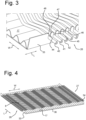
- Figure 3 shows a detail of the tubes 40,41,42 passing through the sidewall 33 via slits 44,45,46 with a V-shaped end part having slanting edges 47, 48.
- the tubes 40, 41, 42 extend along an undulating path in the width direction W in heat conducting contact with the heat exchange substrate 17.
- the tubes 8 extend along a straight line to allow easy handling upon insertion into the slits 44, 45, 46 and easy and accurate automated positioning.
- Figure 4 shows a perspective view of the lower casing member 36 and heat exchange substrate 17, with the tubes 8 supported by the sidewalls 33, 34 and extending from an inflow side 26 to an outflow side 27.
- a number of 30-500 tubes may be accommodated in the arrangement shown.
- the undulating path of the tubes causes turbulence of the gases flowing in the length direction L, over and under the tubes, through the channels of the heat exchange substrates for improved heat transfer.
- Figure 5 shows the width C of the channels 20,21 and the amplitude D and period T of the undulating tubes 8.
- the values of C, D and T are carefully tuned to result in optimal heat transfer of gases flowing through the channels 20,21 in the direction F, and a fluid substance flowing through the tubes 8 in a crossflow manner.
- C:D: T may be about 1:1:5.
- Figure 6 shows the flow of gases flowing through the channels of the upper and lower heat exchange substrates 16, 17 while passing over and under the tubes 8.
- the turbulent flow pattern results in good heat exchange properties.
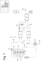
- FIG. 7 shows an internal combustion engine assembly 41 with an internal combustion engine 42 having four cylinders 43.
- a fuel inlet 44 supplies a fuel, that may contain bio-ethanol, for instance in the form of an E10, to the cylinders 43.
- a turbocharger 48 compresses the air that is supplied from an air intake 49 and transports the intake air through a cooler 45 to the intake manifold 51 for supply to the cylinders 43.
- the exhaust gases of the fuel that has been burned in the cylinders 43 leave the engine 42 via an exhaust manifold 52 and flow through an exhaust duct 56 to drive the turbocharger 48.
- the exhaust gases flow via the duct 53 into an integrated catalytic converter/fuel reformer unit 54 that is formed from stacked heat exchange modules that are described in figures 1 to 4 .
- the exhaust gases pass to an ethanol evaporator 57 and from there via exhaust duct 58 to a tail pipe to be expelled into the ambient.
- a pump 63 is connected to a water/ethanol tank 64 and supplies water and ethanol from the tank 64 to the evaporator 57 where the water/ethanol, that is at ambient temperature, is brought in heat exchanging contact with the exhaust gases.
- the ethanol steam and water steam that is produced in the evaporator 57, is supplied via a duct 61 to a pre-heater/cooler unit 75.
- the pre-heated water steam and ethanol steam mixture is fed from the unit 75 to the integrated catalytic converter/fuel reformer unit 54 through duct 76, where the water and steam are flowing through the tubes 8 shown in figures 1-4 , of the reformer unit 54, to be reformed into syngas.
- the exhaust gases flow through the channels of the heat exchange substrates.
- the tubes 8 may be coated with a PGM to activate the reforming process.
- the coating of the tubes may have a different specification of PGM than the coating of the heat exchange substrate, that forms a TWC for the removal of NOx and hydrocarbons from the exhaust gases.
- the exhaust gases flow from the duct 53 in the reformer unit 54 through the channels 20,21 of the top and bottom heat exchange substrates 6,7; 16,16 that are shown in figures 1 and 2 .
- the syngas that is formed in the integrated catalytic converter/fuel reformer unit 54 is transported via a syngas outlet duct 77, through the pre-heater/cooler unit 75 and preheats the water and ethanol by being brought in heat exchanging contact with the water/ethanol steam that is supplied at the inlet of the unit 75.
- the syngas is supplied to a gas inlet ma47nifold 85 that is connected to the cylinders 3.
Landscapes
- Engineering & Computer Science (AREA)
- Physics & Mathematics (AREA)
- General Engineering & Computer Science (AREA)
- Mechanical Engineering (AREA)
- Thermal Sciences (AREA)
- Chemical & Material Sciences (AREA)
- Geometry (AREA)
- Combustion & Propulsion (AREA)
- Chemical Kinetics & Catalysis (AREA)
- Organic Chemistry (AREA)
- Health & Medical Sciences (AREA)
- General Health & Medical Sciences (AREA)
- Inorganic Chemistry (AREA)
- Heat-Exchange Devices With Radiators And Conduit Assemblies (AREA)
Claims (11)
- Wärmeaustauschmodul (2, 3, 4), das Folgendes umfasst:ein gewelltes oberes Wärmeaustauschsubstrat (6) und ein gewelltes unteres Wärmeaustauschsubstrat (7), wobei die Substrate in einer Querrichtung (T) beabstandet sind, wobei jedes Substrat Erhöhungen (19, 20) und Kanäle (18, 21) aufweist, die sich in einer Längsrichtung (L) erstrecken, wobei sich die Kanäle (18) und Erhöhungen (20) des oberen Substrats (6) parallel zu den Kanälen (21) und Erhöhungen (19) des unteren Substrats (7) erstrecken, wobei sich Rohre (8; 23, 24, 25) in einer Breitenrichtung (W) zwischen dem oberen und dem unteren Substrat (6, 7) in Wärmeaustauschkontakt mit den Erhöhungen (19, 20) erstrecken, wobei die Breitenrichtung (W) quer zur Längsrichtung (L) der Kanäle und der Erhöhungen von einer Zuflussseite (26) zu einer Abflussseite (27) ausgerichtet ist,ein oberes und ein unteres Gehäuseelement (35, 36), die Gehäuseoberflächen angrenzend an das obere und das untere Substrat (6, 7) aufweisen, dadurch gekennzeichnet, dass das obere und das untere Gehäuseelement (35, 36) an der Zufluss- und der Abflussseite (26, 27) eine Querseitenwand (32, 33, 34) mit Schlitzen (28, 29, 30) aufweisen, die in Querrichtung (T) ausgerichtet sind und die Rohre (8; 23, 24, 25) aufnehmen, wobei sich die Seitenwände (32, 33) des oberen und des unteren Gehäuseelements (35, 36) überlappen und durch Löten oder Hartlöten miteinander verbunden sind.
- Wärmeaustauschmodul (2, 3, 4) nach Anspruch 1, wobei jedes Substrat (6, 7) entlang einer Gehäuseseitenkante, die entlang eines unteren Teils einer jeweiligen Gehäuseseitenwand (33, 34) liegt, mit einem Gehäuseelement (35, 36) verbunden ist.
- Wärmeaustauschmodul (2, 3, 4) nach Anspruch 1 oder 2, wobei die Rohre (8; 23, 24, 25) an der Position der Querseitenwände (32, 33, 34) einen geraden Abschnitt aufweisen, der sich in der Breitenrichtung (W) quer zu den Seitenwänden (32, 33, 34) erstreckt.
- Wärmeaustauschmodul (2, 3, 4) nach einem der vorhergehenden Ansprüche, wobei die Schlitze (28, 29, 30) in den Seitenwänden (32, 33, 34) an ihrem freien Ende ein V-förmiges Aufnahmeteil (37, 38) zum Führen der Rohre (8; 23, 24, 25) beim Platzieren der Rohre in den Schlitzen (28, 29, 30) umfassen.
- Wärmeaustauschmodul (2, 3, 4) nach einem der vorhergehenden Ansprüche, wobei sich die Rohre (8; 23, 24, 25) entlang einer wellenförmigen Trajektorie mit Wellen in der Breitenrichtung (W) erstrecken.
- Wärmeaustauschmodul (8; 23, 24, 25) nach einem der vorhergehenden Ansprüche, wobei die wellenförmige Trajektorie Biegungsteile in einem Abstand (D) von einer Linie umfasst, die parallel zu der Breitenrichtung (W) ist, wobei ein Abstand (T) der zwei benachbarten Wellen zwischen dem 1,5- und 5-fachen einer Breite (C) eines Kanals (18, 21) beträgt.
- Wärmeaustauschmodul (2, 3, 4) nach einem der vorhergehenden Ansprüche, wobei die Position der Erhöhungen (19) des oberen Substrats (16) in der Breitenrichtung (W) der Position der Kanäle (21) des unteren Substrats (21) entspricht.
- Wärmeaustauschmodul (2, 3, 4) nach einem der vorhergehenden Ansprüche, wobei die Substrate (6, 8) mit einem Metall der Platingruppe beschichtet sind.
- Anordnung (1) aus mindestens zwei Modulen (2, 3, 4) nach einem der vorhergehenden Ansprüche, die übereinander gestapelt sind, wobei die untere Oberfläche des oberen Gehäuseelements an die obere Oberfläche des unteren Gehäuseelements gelötet oder hartgelötet ist.
- Katalysator-/Dampfreformierungsanordnung (54), umfassend ein Wärmeaustauschmodul (2, 3, 4) nach einem der vorhergehenden Ansprüche, wobei Abgase durch die Kanäle (18, 21) und Alkohol und Dampf durch die Rohre (8; 23, 24, 25) geleitet werden.
- Fahrzeug, das Folgendes umfasst:einen Verbrennungsmotor mit Zylindern (43), die mit einem Kraftstoffeinlass (85) und mit einem Abgasauslass (52) verbunden sind, wobei der Abgasauslass in Fluidkontakt mit einer Katalysator-/Dampfreformierungsanordnung (54) nach Anspruch 10 steht, so dass Abgase durch die Kanäle (18, 21) strömen,einen Verdampfer (57), der in Wärmeaustauschkontakt mit den Abgasen steht,eine Wasser- und Ethanolzufuhreinheit (64), die Wasser und Ethanol durch den Verdampfer (57) zum Bilden von Wasser- und Ethanoldampf strömt, wobei Wasser- und Ethanoldampf in die Rohre (8; 23, 24, 25) geleitet werden, undeinen Kanal (81) für reformierten Kraftstoff, der mit einer Abflussseite (27) der Rohre verbunden und mit einem Kraftstoffeinlass (85) der Zylinder (43) verbunden ist.
Priority Applications (3)
| Application Number | Priority Date | Filing Date | Title |
|---|---|---|---|
| EP22166908.8A EP4257911B1 (de) | 2022-04-06 | 2022-04-06 | Wärmeaustauschmodul |
| US18/128,610 US11920505B2 (en) | 2022-04-06 | 2023-03-30 | Heat exchange module |
| CN202310363784.3A CN116892852A (zh) | 2022-04-06 | 2023-04-06 | 换热模块 |
Applications Claiming Priority (1)
| Application Number | Priority Date | Filing Date | Title |
|---|---|---|---|
| EP22166908.8A EP4257911B1 (de) | 2022-04-06 | 2022-04-06 | Wärmeaustauschmodul |
Publications (2)
| Publication Number | Publication Date |
|---|---|
| EP4257911A1 EP4257911A1 (de) | 2023-10-11 |
| EP4257911B1 true EP4257911B1 (de) | 2025-06-11 |
Family
ID=81325718
Family Applications (1)
| Application Number | Title | Priority Date | Filing Date |
|---|---|---|---|
| EP22166908.8A Active EP4257911B1 (de) | 2022-04-06 | 2022-04-06 | Wärmeaustauschmodul |
Country Status (3)
| Country | Link |
|---|---|
| US (1) | US11920505B2 (de) |
| EP (1) | EP4257911B1 (de) |
| CN (1) | CN116892852A (de) |
Family Cites Families (9)
| Publication number | Priority date | Publication date | Assignee | Title |
|---|---|---|---|---|
| FR1429333A (fr) * | 1964-12-31 | 1966-02-25 | Citroen Sa Andre | échangeur thermique à structures chevronnées ondulées |
| SE355233B (de) * | 1971-05-24 | 1973-04-09 | L Andersson | |
| JPH11132688A (ja) * | 1997-10-29 | 1999-05-21 | Denso Corp | 熱交換器 |
| KR100666927B1 (ko) * | 2006-01-20 | 2007-01-10 | 주식회사 두원공조 | 헤더형 열교환기 |
| KR100750794B1 (ko) * | 2006-02-07 | 2007-08-20 | 두산중공업 주식회사 | 간접 내부 개질기를 구비하는 용융탄산염 연료전지 |
| US20100224173A1 (en) * | 2009-03-09 | 2010-09-09 | Herve Palanchon | Heat Exchanger with Cast Housing and Method of Making Same |
| JP5156773B2 (ja) * | 2010-02-25 | 2013-03-06 | 株式会社小松製作所 | コルゲートフィンおよびそれを備える熱交換器 |
| KR20180102335A (ko) * | 2017-03-07 | 2018-09-17 | 주식회사 아모그린텍 | 배기가스를 이용하는 수소 개질기 |
| CN109761193B (zh) * | 2019-03-20 | 2024-04-09 | 浙江工业大学 | 一种甲醇重整制氢反应器 |
-
2022
- 2022-04-06 EP EP22166908.8A patent/EP4257911B1/de active Active
-
2023
- 2023-03-30 US US18/128,610 patent/US11920505B2/en active Active
- 2023-04-06 CN CN202310363784.3A patent/CN116892852A/zh active Pending
Also Published As
| Publication number | Publication date |
|---|---|
| US20230321627A1 (en) | 2023-10-12 |
| CN116892852A (zh) | 2023-10-17 |
| US11920505B2 (en) | 2024-03-05 |
| EP4257911A1 (de) | 2023-10-11 |
Similar Documents
| Publication | Publication Date | Title |
|---|---|---|
| CN101568790B (zh) | 具有旁路的热交换器 | |
| US7195060B2 (en) | Stacked-tube heat exchanger | |
| US9683786B2 (en) | Heat exchanger | |
| KR101168777B1 (ko) | 복수의 관형 어레이를 구비한 열교환기 | |
| US9631876B2 (en) | Heat exchanger | |
| CN202930432U (zh) | 热交换器 | |
| US7988447B2 (en) | Formed sheet heat exchanger | |
| US20170248371A1 (en) | Heat Exchanger | |
| US20130146267A1 (en) | Heat exchanger | |
| US7614389B2 (en) | Exhaust gas heat exchanger, in particular an exhaust gas cooler for exhaust gas recirculation in a motor vehicle | |
| KR20130132427A (ko) | 열 교환기 | |
| WO2006102736A1 (en) | Stacked-tube heat exchanger | |
| US20170122668A1 (en) | Heat exchanger | |
| CN101432589A (zh) | 用于机动车的热交换器 | |
| US20170074594A1 (en) | Plate heat exchanger and method for producing same | |
| US20110017428A1 (en) | Plane type heat exchanger | |
| US20080264622A1 (en) | Bi-material corrosive resistant heat exchanger | |
| JP2001165588A (ja) | 気体−液体熱交換器およびその製造法 | |
| JP2000337215A (ja) | 排気熱交換装置 | |
| EP4257911B1 (de) | Wärmeaustauschmodul | |
| JPH10331725A (ja) | Egrガス冷却装置 | |
| US20070000652A1 (en) | Heat exchanger with dimpled tube surfaces | |
| EP1742005A1 (de) | Verbindungsstruktur für wärmetauscher | |
| JP2007155321A (ja) | 回収熱交換器のような小型の高温熱交換器 | |
| US20160363380A1 (en) | Heat exchanger |
Legal Events
| Date | Code | Title | Description |
|---|---|---|---|
| PUAI | Public reference made under article 153(3) epc to a published international application that has entered the european phase |
Free format text: ORIGINAL CODE: 0009012 |
|
| STAA | Information on the status of an ep patent application or granted ep patent |
Free format text: STATUS: THE APPLICATION HAS BEEN PUBLISHED |
|
| AK | Designated contracting states |
Kind code of ref document: A1 Designated state(s): AL AT BE BG CH CY CZ DE DK EE ES FI FR GB GR HR HU IE IS IT LI LT LU LV MC MK MT NL NO PL PT RO RS SE SI SK SM TR |
|
| STAA | Information on the status of an ep patent application or granted ep patent |
Free format text: STATUS: REQUEST FOR EXAMINATION WAS MADE |
|
| 17P | Request for examination filed |
Effective date: 20240411 |
|
| RBV | Designated contracting states (corrected) |
Designated state(s): AL AT BE BG CH CY CZ DE DK EE ES FI FR GB GR HR HU IE IS IT LI LT LU LV MC MK MT NL NO PL PT RO RS SE SI SK SM TR |
|
| GRAP | Despatch of communication of intention to grant a patent |
Free format text: ORIGINAL CODE: EPIDOSNIGR1 |
|
| STAA | Information on the status of an ep patent application or granted ep patent |
Free format text: STATUS: GRANT OF PATENT IS INTENDED |
|
| INTG | Intention to grant announced |
Effective date: 20241211 |
|
| P01 | Opt-out of the competence of the unified patent court (upc) registered |
Free format text: CASE NUMBER: APP_7011/2025 Effective date: 20250211 |
|
| GRAS | Grant fee paid |
Free format text: ORIGINAL CODE: EPIDOSNIGR3 |
|
| GRAA | (expected) grant |
Free format text: ORIGINAL CODE: 0009210 |
|
| STAA | Information on the status of an ep patent application or granted ep patent |
Free format text: STATUS: THE PATENT HAS BEEN GRANTED |
|
| AK | Designated contracting states |
Kind code of ref document: B1 Designated state(s): AL AT BE BG CH CY CZ DE DK EE ES FI FR GB GR HR HU IE IS IT LI LT LU LV MC MK MT NL NO PL PT RO RS SE SI SK SM TR |
|
| REG | Reference to a national code |
Ref country code: GB Ref legal event code: FG4D |
|
| REG | Reference to a national code |
Ref country code: CH Ref legal event code: EP |
|
| REG | Reference to a national code |
Ref country code: DE Ref legal event code: R096 Ref document number: 602022015710 Country of ref document: DE |
|
| REG | Reference to a national code |
Ref country code: IE Ref legal event code: FG4D |
|
| PG25 | Lapsed in a contracting state [announced via postgrant information from national office to epo] |
Ref country code: FI Free format text: LAPSE BECAUSE OF FAILURE TO SUBMIT A TRANSLATION OF THE DESCRIPTION OR TO PAY THE FEE WITHIN THE PRESCRIBED TIME-LIMIT Effective date: 20250611 Ref country code: ES Free format text: LAPSE BECAUSE OF FAILURE TO SUBMIT A TRANSLATION OF THE DESCRIPTION OR TO PAY THE FEE WITHIN THE PRESCRIBED TIME-LIMIT Effective date: 20250611 |
|
| REG | Reference to a national code |
Ref country code: LT Ref legal event code: MG9D |
|
| PG25 | Lapsed in a contracting state [announced via postgrant information from national office to epo] |
Ref country code: NO Free format text: LAPSE BECAUSE OF FAILURE TO SUBMIT A TRANSLATION OF THE DESCRIPTION OR TO PAY THE FEE WITHIN THE PRESCRIBED TIME-LIMIT Effective date: 20250911 Ref country code: GR Free format text: LAPSE BECAUSE OF FAILURE TO SUBMIT A TRANSLATION OF THE DESCRIPTION OR TO PAY THE FEE WITHIN THE PRESCRIBED TIME-LIMIT Effective date: 20250912 |
|
| REG | Reference to a national code |
Ref country code: NL Ref legal event code: MP Effective date: 20250611 |
|
| PG25 | Lapsed in a contracting state [announced via postgrant information from national office to epo] |
Ref country code: BG Free format text: LAPSE BECAUSE OF FAILURE TO SUBMIT A TRANSLATION OF THE DESCRIPTION OR TO PAY THE FEE WITHIN THE PRESCRIBED TIME-LIMIT Effective date: 20250611 |
|
| PG25 | Lapsed in a contracting state [announced via postgrant information from national office to epo] |
Ref country code: HR Free format text: LAPSE BECAUSE OF FAILURE TO SUBMIT A TRANSLATION OF THE DESCRIPTION OR TO PAY THE FEE WITHIN THE PRESCRIBED TIME-LIMIT Effective date: 20250611 |
|
| PG25 | Lapsed in a contracting state [announced via postgrant information from national office to epo] |
Ref country code: RS Free format text: LAPSE BECAUSE OF FAILURE TO SUBMIT A TRANSLATION OF THE DESCRIPTION OR TO PAY THE FEE WITHIN THE PRESCRIBED TIME-LIMIT Effective date: 20250911 |
|
| PG25 | Lapsed in a contracting state [announced via postgrant information from national office to epo] |
Ref country code: LV Free format text: LAPSE BECAUSE OF FAILURE TO SUBMIT A TRANSLATION OF THE DESCRIPTION OR TO PAY THE FEE WITHIN THE PRESCRIBED TIME-LIMIT Effective date: 20250611 |
|
| PG25 | Lapsed in a contracting state [announced via postgrant information from national office to epo] |
Ref country code: NL Free format text: LAPSE BECAUSE OF FAILURE TO SUBMIT A TRANSLATION OF THE DESCRIPTION OR TO PAY THE FEE WITHIN THE PRESCRIBED TIME-LIMIT Effective date: 20250611 |
|
| PG25 | Lapsed in a contracting state [announced via postgrant information from national office to epo] |
Ref country code: PT Free format text: LAPSE BECAUSE OF FAILURE TO SUBMIT A TRANSLATION OF THE DESCRIPTION OR TO PAY THE FEE WITHIN THE PRESCRIBED TIME-LIMIT Effective date: 20251013 |
|
| REG | Reference to a national code |
Ref country code: AT Ref legal event code: MK05 Ref document number: 1802559 Country of ref document: AT Kind code of ref document: T Effective date: 20250611 |
|
| PG25 | Lapsed in a contracting state [announced via postgrant information from national office to epo] |
Ref country code: IS Free format text: LAPSE BECAUSE OF FAILURE TO SUBMIT A TRANSLATION OF THE DESCRIPTION OR TO PAY THE FEE WITHIN THE PRESCRIBED TIME-LIMIT Effective date: 20251011 |
|
| PG25 | Lapsed in a contracting state [announced via postgrant information from national office to epo] |
Ref country code: SM Free format text: LAPSE BECAUSE OF FAILURE TO SUBMIT A TRANSLATION OF THE DESCRIPTION OR TO PAY THE FEE WITHIN THE PRESCRIBED TIME-LIMIT Effective date: 20250611 Ref country code: AT Free format text: LAPSE BECAUSE OF FAILURE TO SUBMIT A TRANSLATION OF THE DESCRIPTION OR TO PAY THE FEE WITHIN THE PRESCRIBED TIME-LIMIT Effective date: 20250611 |
|
| PG25 | Lapsed in a contracting state [announced via postgrant information from national office to epo] |
Ref country code: CZ Free format text: LAPSE BECAUSE OF FAILURE TO SUBMIT A TRANSLATION OF THE DESCRIPTION OR TO PAY THE FEE WITHIN THE PRESCRIBED TIME-LIMIT Effective date: 20250611 |
|
| PG25 | Lapsed in a contracting state [announced via postgrant information from national office to epo] |
Ref country code: PL Free format text: LAPSE BECAUSE OF FAILURE TO SUBMIT A TRANSLATION OF THE DESCRIPTION OR TO PAY THE FEE WITHIN THE PRESCRIBED TIME-LIMIT Effective date: 20250611 |
|
| PG25 | Lapsed in a contracting state [announced via postgrant information from national office to epo] |
Ref country code: EE Free format text: LAPSE BECAUSE OF FAILURE TO SUBMIT A TRANSLATION OF THE DESCRIPTION OR TO PAY THE FEE WITHIN THE PRESCRIBED TIME-LIMIT Effective date: 20250611 |
|
| PG25 | Lapsed in a contracting state [announced via postgrant information from national office to epo] |
Ref country code: SK Free format text: LAPSE BECAUSE OF FAILURE TO SUBMIT A TRANSLATION OF THE DESCRIPTION OR TO PAY THE FEE WITHIN THE PRESCRIBED TIME-LIMIT Effective date: 20250611 |