EP4257902A1 - Integrierte wasserwegvorrichtung und kühlschrank damit - Google Patents
Integrierte wasserwegvorrichtung und kühlschrank damit Download PDFInfo
- Publication number
- EP4257902A1 EP4257902A1 EP21917175.8A EP21917175A EP4257902A1 EP 4257902 A1 EP4257902 A1 EP 4257902A1 EP 21917175 A EP21917175 A EP 21917175A EP 4257902 A1 EP4257902 A1 EP 4257902A1
- Authority
- EP
- European Patent Office
- Prior art keywords
- water
- filter
- water inlet
- bottle
- filter cartridge
- Prior art date
- Legal status (The legal status is an assumption and is not a legal conclusion. Google has not performed a legal analysis and makes no representation as to the accuracy of the status listed.)
- Pending
Links
- XLYOFNOQVPJJNP-UHFFFAOYSA-N water Substances O XLYOFNOQVPJJNP-UHFFFAOYSA-N 0.000 title claims description 409
- 238000003780 insertion Methods 0.000 claims description 59
- 230000037431 insertion Effects 0.000 claims description 59
- 238000010586 diagram Methods 0.000 description 9
- 230000006872 improvement Effects 0.000 description 8
- 238000007789 sealing Methods 0.000 description 5
- 230000009471 action Effects 0.000 description 3
- 230000000694 effects Effects 0.000 description 3
- 230000002441 reversible effect Effects 0.000 description 3
- 238000000034 method Methods 0.000 description 2
- 230000007797 corrosion Effects 0.000 description 1
- 238000005260 corrosion Methods 0.000 description 1
- 239000002184 metal Substances 0.000 description 1
- 230000004048 modification Effects 0.000 description 1
- 238000012986 modification Methods 0.000 description 1
- 230000000737 periodic effect Effects 0.000 description 1
- 230000008569 process Effects 0.000 description 1
- 230000003014 reinforcing effect Effects 0.000 description 1
- 230000008439 repair process Effects 0.000 description 1
- 238000005728 strengthening Methods 0.000 description 1
- 230000001360 synchronised effect Effects 0.000 description 1
- 230000009466 transformation Effects 0.000 description 1
- 238000000844 transformation Methods 0.000 description 1
- 230000007704 transition Effects 0.000 description 1
Images


Classifications
-
- C—CHEMISTRY; METALLURGY
- C02—TREATMENT OF WATER, WASTE WATER, SEWAGE, OR SLUDGE
- C02F—TREATMENT OF WATER, WASTE WATER, SEWAGE, OR SLUDGE
- C02F1/00—Treatment of water, waste water, or sewage
- C02F1/001—Processes for the treatment of water whereby the filtration technique is of importance
-
- F—MECHANICAL ENGINEERING; LIGHTING; HEATING; WEAPONS; BLASTING
- F25—REFRIGERATION OR COOLING; COMBINED HEATING AND REFRIGERATION SYSTEMS; HEAT PUMP SYSTEMS; MANUFACTURE OR STORAGE OF ICE; LIQUEFACTION SOLIDIFICATION OF GASES
- F25D—REFRIGERATORS; COLD ROOMS; ICE-BOXES; COOLING OR FREEZING APPARATUS NOT OTHERWISE PROVIDED FOR
- F25D11/00—Self-contained movable devices, e.g. domestic refrigerators
-
- F—MECHANICAL ENGINEERING; LIGHTING; HEATING; WEAPONS; BLASTING
- F25—REFRIGERATION OR COOLING; COMBINED HEATING AND REFRIGERATION SYSTEMS; HEAT PUMP SYSTEMS; MANUFACTURE OR STORAGE OF ICE; LIQUEFACTION SOLIDIFICATION OF GASES
- F25D—REFRIGERATORS; COLD ROOMS; ICE-BOXES; COOLING OR FREEZING APPARATUS NOT OTHERWISE PROVIDED FOR
- F25D17/00—Arrangements for circulating cooling fluids; Arrangements for circulating gas, e.g. air, within refrigerated spaces
- F25D17/02—Arrangements for circulating cooling fluids; Arrangements for circulating gas, e.g. air, within refrigerated spaces for circulating liquids, e.g. brine
-
- F—MECHANICAL ENGINEERING; LIGHTING; HEATING; WEAPONS; BLASTING
- F25—REFRIGERATION OR COOLING; COMBINED HEATING AND REFRIGERATION SYSTEMS; HEAT PUMP SYSTEMS; MANUFACTURE OR STORAGE OF ICE; LIQUEFACTION SOLIDIFICATION OF GASES
- F25D—REFRIGERATORS; COLD ROOMS; ICE-BOXES; COOLING OR FREEZING APPARATUS NOT OTHERWISE PROVIDED FOR
- F25D23/00—General constructional features
- F25D23/12—Arrangements of compartments additional to cooling compartments; Combinations of refrigerators with other equipment, e.g. stove
-
- F—MECHANICAL ENGINEERING; LIGHTING; HEATING; WEAPONS; BLASTING
- F25—REFRIGERATION OR COOLING; COMBINED HEATING AND REFRIGERATION SYSTEMS; HEAT PUMP SYSTEMS; MANUFACTURE OR STORAGE OF ICE; LIQUEFACTION SOLIDIFICATION OF GASES
- F25D—REFRIGERATORS; COLD ROOMS; ICE-BOXES; COOLING OR FREEZING APPARATUS NOT OTHERWISE PROVIDED FOR
- F25D23/00—General constructional features
- F25D23/12—Arrangements of compartments additional to cooling compartments; Combinations of refrigerators with other equipment, e.g. stove
- F25D23/126—Water cooler
-
- C—CHEMISTRY; METALLURGY
- C02—TREATMENT OF WATER, WASTE WATER, SEWAGE, OR SLUDGE
- C02F—TREATMENT OF WATER, WASTE WATER, SEWAGE, OR SLUDGE
- C02F2201/00—Apparatus for treatment of water, waste water or sewage
- C02F2201/002—Construction details of the apparatus
- C02F2201/004—Seals, connections
-
- C—CHEMISTRY; METALLURGY
- C02—TREATMENT OF WATER, WASTE WATER, SEWAGE, OR SLUDGE
- C02F—TREATMENT OF WATER, WASTE WATER, SEWAGE, OR SLUDGE
- C02F2201/00—Apparatus for treatment of water, waste water or sewage
- C02F2201/002—Construction details of the apparatus
- C02F2201/006—Cartridges
-
- C—CHEMISTRY; METALLURGY
- C02—TREATMENT OF WATER, WASTE WATER, SEWAGE, OR SLUDGE
- C02F—TREATMENT OF WATER, WASTE WATER, SEWAGE, OR SLUDGE
- C02F2307/00—Location of water treatment or water treatment device
- C02F2307/10—Location of water treatment or water treatment device as part of a potable water dispenser, e.g. for use in homes or offices
-
- F—MECHANICAL ENGINEERING; LIGHTING; HEATING; WEAPONS; BLASTING
- F25—REFRIGERATION OR COOLING; COMBINED HEATING AND REFRIGERATION SYSTEMS; HEAT PUMP SYSTEMS; MANUFACTURE OR STORAGE OF ICE; LIQUEFACTION SOLIDIFICATION OF GASES
- F25D—REFRIGERATORS; COLD ROOMS; ICE-BOXES; COOLING OR FREEZING APPARATUS NOT OTHERWISE PROVIDED FOR
- F25D2323/00—General constructional features not provided for in other groups of this subclass
- F25D2323/121—General constructional features not provided for in other groups of this subclass the refrigerator is characterised by a water filter for the water/ice dispenser
-
- F—MECHANICAL ENGINEERING; LIGHTING; HEATING; WEAPONS; BLASTING
- F25—REFRIGERATION OR COOLING; COMBINED HEATING AND REFRIGERATION SYSTEMS; HEAT PUMP SYSTEMS; MANUFACTURE OR STORAGE OF ICE; LIQUEFACTION SOLIDIFICATION OF GASES
- F25D—REFRIGERATORS; COLD ROOMS; ICE-BOXES; COOLING OR FREEZING APPARATUS NOT OTHERWISE PROVIDED FOR
- F25D2323/00—General constructional features not provided for in other groups of this subclass
- F25D2323/122—General constructional features not provided for in other groups of this subclass the refrigerator is characterised by a water tank for the water/ice dispenser
Definitions
- the present invention relates to the field of filters, and in particular, to a water-circuit integrated device and a refrigerator having the same.
- the water-circuit integrated device generally includes a filter, a water valve, a water bottle and other devices which are connected in sequence, and a housing is usually provided to integrate the filter, the water valve and the water bottle together.
- the filter is configured to filter and purify external water
- the water bottle is configured to store filtered water to allow the filtered water to be cooled in a refrigerator
- the water valve is configured to control flow of the water or distribution of the water; for example, the water is divided into two paths and then supplied to a dispenser and an ice maker.
- the filter generally includes a filter cartridge and a connector, the connector is provided with a water inlet and a water outlet and generally fixedly provided in a water circuit module, and the filter cartridge is required to be detachably connected to the connector due to periodic replacement.
- An object of the present invention is to provide a water-circuit integrated device and a refrigerator having the same.
- an embodiment of the present invention provides a water-circuit integrated device, comprising a filter and a filter housing with an opening, wherein the filter comprises a connector and a filter cartridge rotatably connected to the connector, the filter cartridge is inserted into the filter housing through the opening, and the connector is provided at an end in the filter housing apart from the opening; the filter cartridge comprises a first end close to the connector and a second end provided opposite to the first end, a clamping part is provided on a circumference of the first end, and a buckling part fitted with the clamping part is provided on the connector; when the filter cartridge is located at a butted position of the filter cartridge and the connector, the clamping part and the buckling part are provided front and back in an axial direction and adjacent in a circumferential direction; when the filter cartridge is located at a mounting finished position, the clamping part and the buckling part are provided front and back in the axial direction and staggered in the circumferential direction.
- the filter housing comprises a first circular arc section and a second circular arc section which enclose a cylinder; the first circular arc section can be matched with the insertion of the filter cartridge into the filter housing, and the second circular arc section can interfere with the insertion of the filter cartridge into the filter housing.
- the first circular arc section has an arc length equal to a circumferential dimension of the clamping part.
- a support portion is provided on the second circular arc section, the support portion protrudes towards an interior of the filter housing, and when the filter cartridge is inserted into the filter housing, the support portion abuts against the filter cartridge.
- the water valve is selectively communicated with the water bottle through a water-bottle water inlet assembly;
- the water-bottle water inlet assembly comprises a water inlet sleeve and a water inlet insertion part rotatably inserted into the water inlet sleeve, and water inlet flow channels which can be mutually communicated are provided in the water inlet insertion part and the water inlet sleeve.
- the water inlet sleeve extends outwards from a water inlet of the water bottle, and the water inlet sleeve and the water bottle are integrally formed; the water inlet insertion part extends outwards from a water outlet of the water valve, and the water inlet insertion part and the water valve are integrally formed.
- the present invention discloses a refrigerator including a refrigerating chamber, wherein the water-circuit integrated device according to any one of the above descriptions is mounted in the refrigerating chamber.
- a dispenser and an ice maker comprising a dispenser and an ice maker, the ice maker being connected with an ice maker water supply pipe, and the dispenser being connected with a dispenser water supply pipe,
- the clamping part is provided on the filter cartridge
- the buckling part is provided on the connector
- the clamping part and the buckling part are provided front and back in the axial direction and adjacent in the circumferential direction.
- the clamping part and the buckling part can be staggered in the circumferential direction only by rotating the filter cartridge, such that the clamping part is in snapped connection with the buckling part, the filter cartridge may be located at the mounting finished position, and therefore, a mounting mode of the filter cartridge is easy; the filter cartridge can be detached only by reverse rotation, thus facilitating an operation of a user.
- an embodiment of the present invention discloses a water-circuit integrated device.
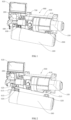
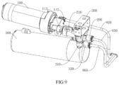
- the water-circuit integrated device includes a filter 100, a water valve 200 and a water bottle 300 communicated in sequence, the water bottle 300 includes a proximal end 310 and a distal end 320 arranged oppositely in a length direction, the proximal end 310 of the water bottle 300 is detachably connected with the water valve 200 by a water-bottle water inlet assembly 400, and the distal end 310 of the water bottle 300 is detachably connected with the filter 100 by a distal-end snapping assembly 500.
- the water-bottle water inlet assembly 400 includes a rotation axis perpendicular to the length direction of the water bottle 300. During snapped connection of the distal-end snapping assembly 500, the water-bottle water inlet assembly 400 realizes locked connection in an axial direction of the rotation axis. When the water-bottle water inlet assembly 400 is released in the axial direction of the rotation axis, the distal-end snapping assembly 500 is released from the snapped connection.
- one end of the water bottle 300 is detachably connected with the water valve 200 by the water-bottle water inlet assembly 400, and the other end of the water bottle is detachably connected with the filter 100 by the distal-end snapping assembly 500, such that during snapped connection of the distal-end snapping assembly 500, the water-bottle water inlet assembly 400 also realizes locked connection, and the water bottle 300, the water valve 200 and the filter 100 can be connected together.
- the distal-end snapping assembly 500 is just released from the snapped connection, such that the water bottle 300 can be smoothly detached from the water valve 200 and the filter 100. Therefore, the water bottle 300 can be conveniently connected with or detached from the water valve 200 and the filter 100 by fitting of the water-bottle water inlet assembly 400 and the distal-end snapping assembly 500, such that the water bottle 300 can be conveniently replaced or repaired subsequently.
- the water-bottle water inlet assembly 400 is released in the axial direction of the rotation axis. That is, when the distal-end snapping assembly 500 is released from the snapped connection, the water-bottle water inlet assembly 400 is also released in the axial direction of the rotation axis, and at this point, the water bottle 300 can be detached from the water valve 200 and the filter 100.
- state transitions of the water-bottle water inlet assembly 400 and the distal-end snapping assembly 500 are completely consistent, such that a stroke of a rotation operation can be shortened, and an operation of mounting or dismounting the water bottle 300 is simpler and more convenient.
- a direction of the locked connection of the water-bottle water inlet assembly 400 is different from a direction of the snapped connection of the distal-end snapping assembly 500. That is, the water-bottle water inlet assembly 400 and the distal-end snapping assembly 500 are connected with the water bottle in different directions, thereby further reinforcing the connection of the water bottle 300 with the water valve 200 and the filter 100; the connection in the two different directions does not interfere, such that the water bottle 300 is not easily released and dropped even when the assembly in one direction fails.
- the direction of the locked connection of the water-bottle water inlet assembly 400 is the axial direction of the rotation axis
- the direction of the snapped connection of the distal-end snapping assembly 500 is perpendicular to the axial direction of the rotation axis. That is, directions of the connection of the water-bottle water inlet assembly 400 and the distal-end snapping assembly 500 to the water bottle are perpendicular to each other. Mutual interference of the connection in the two directions can be reduced to the minimum, such that the connection of the water bottle is firmer.
- the distal-end snapping assembly 500 includes a distal-end snapping portion and a distal-end fitting portion which can be snapped to or separated from the distal-end snapping portion, the distal-end snapping portion is provided on one of the water bottle 300 and the filter 100, and the distal-end fitting portion is provided on the other of the water bottle 300 and the filter 100.
- the snapping or separating operation can be easily realized by mutual fitting of the distal-end snapping portion and the distal-end fitting portion.
- the distal-end snapping portion is provided on the filter 100
- the distal-end fitting portion is provided on the water bottle 300.
- the distal-end snapping portion is configured as a distal-end hanging buckle 510 provided on the filter 100
- the distal-end fitting portion is configured as a distal-end hanging hole 520 provided on the water bottle 300, and during the snapped connection of the distal-end snapping assembly 500, the distal-end hanging buckle 510 is inserted into the distal-end hanging hole 520.
- the connection by the hanging buckle and the hanging hole has a simple structure and a low cost, and is easy to operate.
- the snapped connection of the distal-end snapping assembly 500 may be realized directly by inserting the distal-end hanging buckle 510 into the distal-end hanging hole 520.
- a thread may be provided in the distal-end hanging buckle 510, and when the distal-end hanging buckle 510 is inserted into the distal-end hanging hole 520, a screw is screwed into and in threaded connection with the distal-end hanging buckle 510, and an end surface of the screw abuts against an edge of the hanging hole 520.
- the distal-end hanging buckle may also be in interference fit with the distal-end hanging hole. Therefore, in a transportation/assembly process of the water-circuit integrated device or a refrigerator, even when conditions of collision or shaking, or the like, are generated, the distal end of the water bottle cannot be easily disconnected.
- the distal-end hanging buckle 510 may extend outwards from a housing of the filter 100, the distal-end hanging buckle 510 and the housing of the filter 100 may be integrally formed, the distal-end hanging hole 520 may extend outwards from the water bottle 300, and the distal-end hanging hole 520 and the water bottle 300 may be integrally formed.
- the arrangement of the integrally formed structure makes the connection between the water bottle 300 and the filter 100 more stable and firmer.
- distal-end snapping portion and the distal-end fitting portion may be of other structures in snapped connection.
- the proximal end 310 of the water bottle 300 is also detachably connected with the filter 100 by a proximal-end snapping assembly 600.
- the proximal-end snapping assembly 600 realizes snapped connection.
- the proximal-end snapping assembly 600 is released from the snapped connection.
- the proximal-end snapping assembly 600 is provided at the proximal end 310 of the water bottle 300, thereby further strengthening the connection at the proximal end 310 of the water bottle 300.
- the proximal-end snapping assembly 600 can also be fitted with the water-bottle water inlet assembly 400 and the distal-end snapping assembly 500 to realize synchronous connection or detachment.
- the proximal-end snapping assembly 600 also includes a proximal-end snapping portion 610 and a proximal-end fitting portion 620 which can be snapped to or separated from the proximal-end snapping portion 610, and in the embodiment of the present invention, the proximal-end snapping portion is configured as a proximal-end hanging buckle 610, and the proximal-end fitting portion is configured as a proximal-end hanging hole 620.
- the water bottle 300 and the water valve 200 are also selectively communicated by the water-bottle water inlet assembly 400
- the water-bottle water inlet assembly 400 includes: a water inlet sleeve 410 and a water inlet insertion part 420 rotatably inserted into the water inlet sleeve 410.
- the water inlet insertion part 420 and the water inlet sleeve 410 are provided therein with water inlet flow channels which can be communicated with each other.
- the water inlet sleeve 410 is provided on one of the water bottle 300 and the water valve 200
- the water inlet insertion part 420 is provided on the other of the water bottle 300 and the water valve 200.
- the water inlet insertion part 420 is provided with a water inlet limiting protrusion 421, and the water inlet sleeve 410 includes a water inlet cylinder 411, a water inlet insertion port 412 formed on the water inlet cylinder 411 and a water inlet limiting hole 413 provided in a circumferential direction of the water inlet cylinder 411.
- the water inlet sleeve 410 is further provided with a water inlet guide groove 414 matched with the water inlet limiting protrusion 421, and the water inlet guide groove 414 extends axially from the water inlet insertion port 412 along the water inlet sleeve 410 and is communicated with an end portion of the water inlet limiting hole 413.
- a dimension H of the water inlet limiting hole 413 is greater than a dimension L of the water inlet guide groove 414. That is, the water-bottle water inlet assembly 400 not only serves to connect the water bottle 300 and the water valve 200, but also serves to allow water to pass therethrough, that is, allow water in the water valve 200 to flow into the water bottle 300, after the connection.
- the water valve 200 has two water outlets, one of the two water outlets extends outwards to form the water inlet insertion part 420, and an inlet of the water bottle 300 extends outwards to form the water inlet sleeve 410, such that the water can flow through the water inlet insertion part 420 and the water inlet sleeve 410 after the water inlet insertion part 420 and the water inlet sleeve 410 are connected.
- the dimension H of the water inlet limiting hole 413 is set to be greater than the dimension L of the water inlet guide groove 414, such that when the water inlet insertion part 420 is inserted into the water inlet sleeve 410, the water inlet limiting protrusion 421 on the water inlet insertion part 420 can enter the water inlet guide groove 414 from the water inlet insertion port 412 on the water inlet sleeve 410, and then, the water bottle 300 is rotated along the rotation axis in a first direction, and the water inlet limiting protrusion 421 can enter the water inlet limiting hole 413; since the dimension H of the water inlet limiting hole 413 is larger and the water inlet limiting hole 413 is not communicated with the water inlet insertion port 412, at this point, the water inlet limiting protrusion 421 and the water inlet limiting hole 413 are in snap fit, such that even when
- the water bottle 300 is rotated along the rotation axis in a direction opposite to the first direction, such that the water inlet limiting protrusion 421 is aligned with the water inlet guide groove 414, thereby releasing the water-bottle water inlet assembly 400 in the axial direction of the rotation axis.
- the water inlet limiting protrusion 421 can move towards the water inlet insertion port 412 along the water inlet guide groove 414 by applying a force in the direction opposite to the insertion direction, and finally, the water inlet insertion part 420 reversely exits from the water inlet sleeve 410.
- the rotation axis is configured as a central axis X of the water inlet sleeve 410. That is, by rotating the water bottle 300 about the central axis X of the water inlet sleeve 410, the water-bottle water inlet assembly 400 can be locked or released, and the distal-end snapping assembly 500 can realize snapped connection or be released from the snapped connection.
- the connection and detachment of the water bottle 300 are simple, and an operation of a user is convenient.
- the water inlet sleeve 410 extends outwards from a water inlet of the water bottle 300, and the water inlet sleeve 410 and the water bottle 300 are integrally formed.
- the water inlet insertion part 420 extends outwards from a water outlet of the water valve 200, and the water inlet insertion part 420 and the water valve 200 are integrally formed.
- the water inlet insertion part 420 includes a first insertion portion 422 and a second insertion portion 423 provided at a front end of the first insertion portion 422, and an outer diameter of the second insertion portion 423 is less than an outer diameter of the first insertion portion 422.
- the second insertion portion 423 having a less inner diameter is inserted into the water inlet sleeve 410 first, such that a guiding function can be provided for an insertion action, and the connection of the water-bottle water inlet assembly 400 is easier.
- the second insertion portion 423 is sleeved with a sealing part
- the sealing part 4231 is configured to fill a gap between an outer wall of the second insertion portion 423 and an inner wall of the water inlet sleeve 410, thereby preventing water leakage. Specifically, an inner diameter at a position of the water inlet sleeve 410 corresponding to the sealing part 4231 on the second insertion portion 423 is reduced, such that the sealing part 4231 is pressed between the inner wall of the water inlet sleeve 410 and the second insertion portion 423 to further enhance a sealing effect.
- the water inlet insertion part 420 further includes a stopper 424 connected with the first insertion portion 421, and an end surface of the stopper 424 abuts against an end surface of the water inlet sleeve 410.
- the stopper 424 serves as a terminal point of insertion of the water inlet insertion part 420 into the water inlet sleeve 410; that is, when the water inlet insertion part is inserted into the water inlet sleeve 410, and the end surface of the stopper 424 is seen to abut against the end surface of the water inlet sleeve 410, the insertion action can be determined to be in place.
- the water inlet insertion part 420 is provided with two water inlet limiting protrusions 421, the two water inlet limiting protrusions 421 are symmetrically arranged relative to an axis of the water inlet insertion part 420, and two water inlet guide grooves 413 are arranged at positions on the water inlet sleeve corresponding to the two water inlet limiting protrusions 421.
- the two symmetrical water inlet limiting protrusions 421 and the two corresponding water inlet guide grooves 413 are arranged, such that the water inlet insertion part 420 and the water inlet sleeve 410 can be locked more firmly and stably.
- the filter 100 and the water valve 200 are selectively communicated through a filter water outlet assembly 700.
- the filter water outlet assembly 700 includes: a water outlet sleeve 710 and a water outlet insertion part 720 rotatably inserted into the water outlet sleeve 710.
- the filter water outlet assembly 700, the water outlet sleeve 710 and the water outlet insertion part 720 have identical structures to and different positions from the water-bottle water inlet assembly 400, the water inlet sleeve 410 and the water inlet insertion part 420. Therefore, the detailed structure of the filter water outlet assembly 700 is not repeated.
- the filter 100, the water valve 200 and the water bottle 300 are adjacently arranged two by two, and the water-bottle water inlet assembly 400 is perpendicular to the filter water outlet assembly 700. That is, the central axis X of the water outlet sleeve 710 is perpendicular to the central axis of the water inlet sleeve 410.
- the water-circuit integrated device further includes a housing 800, and the housing 800 encloses the filter 100 and the water valve 200. Specifically, the housing 800 also functions to connect the water-circuit integrated device to the refrigerator. In addition, the distal-end hanging buckle 510 is also provided on the housing 800, such that the connection of the water bottle 300 is more stable.
- the integrated bracket 800 includes a filter housing 810, a water valve housing 820 and a fixing portion 830 connected with each other, the filter housing 810 accommodates the filter 100, the water valve housing 820 accommodates the water valve 200, and the water bottle 300 is connected with the fixing portion 830.
- the filter housing 810 has an opening 811, the filter 100 includes a connector 110 and a filter cartridge 120 rotatably connected with the connector 110, the filter cartridge 120 is inserted into the filter housing 810 through the opening 811, and the connector 110 is provided at an end in the filter housing 810 apart from the opening 811.
- the filter cartridge 120 includes a first end 121 close to the connector 110 and a second end 122 provided opposite to the first end 121, a clamping part 1211 is provided on a circumference of the first end 121, and a buckling part 111 fitted with the clamping part 1211 is provided on the connector 110.
- the clamping part 1211 and the buckling part 111 are provided back and forth in an axial direction and adjacent in a circumferential direction.
- the clamping part 1211 and the buckling part 111 are provided front and back in the axial direction and staggered in the circumferential direction.
- the butted position is configured as a position where the filter cartridge 120 is inserted into the filter housing 810 until the filter cartridge cannot be inserted further, and at this point, the filter cartridge 120 and the connector 110 are in butt connection and in an unlocked state in the axial direction; that is, the filter cartridge 120 can be drawn out of the filter housing 810 at any time.
- the mounting finished position is configured as a position where the filter cartridge 120 and the connector 110 are locked under an action of the clamping part 1211 and the buckling part 111 in the axial direction, and at this point, the filter cartridge 120 cannot be drawn out of the filter housing 810.
- the clamping part 1211 is provided on the filter cartridge 120
- the buckling part 111 is provided on the connector 110
- the clamping part 1211 and the buckling part 111 are provided front and back in the axial direction and adjacent in the circumferential direction.
- the clamping part 1211 and the buckling part 111 can be staggered in the circumferential direction only by rotating the filter cartridge 120, such that the clamping part 1211 is in snapped connection with the buckling part 111, the filter cartridge 120 may be located at the mounting finished position, and therefore, a mounting of the filter cartridge 120 is easy; the filter cartridge 120 can be detached only by reverse rotation, thus facilitating an operation of a user.
- the filter housing 810 includes a first circular arc section 812 and a second circular arc section 813 which enclose a cylinder.
- the first circular arc section 812 can be matched with the insertion of the filter cartridge 120 into the filter housing 810, and the second circular arc section 813 can interfere with the insertion of the filter cartridge 120 into the filter housing 810.
- the filter cartridge 120 is generally cylindrical, and a filter medium is provided inside the filter cartridge.
- the user may rotate the filter cartridge 120 at will, but since each of the connector 110 and the filter cartridge 120 is provided with water inlet and outlet terminals, the terminals can be in butt connection at predefined angles, the connector 110 and the filter cartridge 120 are required to be rotated for snapped connection after the butt connection, and the connector 110 is provided inside the filter housing 810, butted and connected parts of the filter cartridge 120 and the connector 110 cannot be seen after the filter cartridge 120 is inserted into the filter housing 810, and therefore, after the filter cartridge 120 is inserted, there may exist problems that the water inlet and outlet terminals of the filter cartridge 120 and the connector 110 cannot be in butt connection, and the filter cartridge 120 cannot be in correct snapped connection with the connector 110 even after rotated a plurality of times.
- the filter housing 810 is divided into the first circular arc section 812 and the second circular arc section 813, and the clamping part 1211 on the filter cartridge 120 is aligned with the first circular arc section 812
- the filter cartridge 120 can be inserted into the filter housing 810, and when the filter cartridge 120 rotates and the clamping part 1211 is aligned with the second circular arc section 813, the second circular arc section 813 interferes with the filter cartridge 120, such that a rotation angle of the filter cartridge 120 can be limited, and the filter cartridge 120 can be inserted into the filter housing 810 at a predetermined angle, so as to be in smooth butt connection with the connector 110, and can be smoothly rotated and then be in snapped connection with the connector 110.
- the first circular arc section 812 has an arc length equal to a circumferential dimension of the clamping part 1211.
- the arc length of the first circular arc section 812 is matched with the dimension of the clamping part 1211, such that a prompt is provided for the user, and the user can insert the filter cartridge 120 into the filter housing 810 by aligning the first circular arc section and the clamping part, thus facilitating mounting of the filter cartridge 120.
- a support portion 8131 is provided on the second circular arc section 813, the support portion 8131 protrudes towards an interior of the filter housing 810, and when the filter cartridge 120 is inserted into the filter housing 810, the support portion 8131 abuts against the filter cartridge 120.
- the support portion 8131 is provided to support the filter cartridge 120 after the filter cartridge is connected with the connector 110, such that the filter cartridge is not suspended, and the filter cartridge 120 is more stable after mounted.
- the filter housing 810, the water valve housing 820 and the fixing portion 830 are integrally formed.
- the integrally formed integrated bracket has a more stable structure, and when the water-circuit integrated device is assembled, the filter 100, the water valve 200 and the water bottle 300 are connected with the integrated bracket 800, such that a connection mode is simple.
- the filter 100, the water valve 200 and the water bottle 300 are adjacent to each other, and the filter 100 and the water bottle 300 are provided at an angle. Since bubbles may be generated in the water bottle 300, and have different sizes, a burst may corrode or damage metal components of the water bottle 300, and a water hammer effect may be generated.
- the water bottle 300 and the filter 100 are arranged at an angle of 5 degrees, thus ensuring that the bubbles in the water bottle 300 flow out of a water storage space in the water bottle 300, reducing the water hammer effect, and reducing a probability of corrosion or damage to the water bottle 300.
- the filter 100, the water valve 200, and the water bottle 300 are adjacent to each other, and the filter 100 and the water bottle 300 are provided in parallel.
- an overall dimension of the water-circuit integrated device may be more compact, and more spaces are saved.
- An embodiment of the present invention further discloses a refrigerator including a refrigerating chamber, wherein the water-circuit integrated device is mounted in the refrigerating chamber.
- the refrigerator includes a dispenser and an ice maker
- the ice maker is connected with an ice maker water supply pipe 950
- the dispenser is connected with a dispenser water supply pipe 960
- the connector 110 is provided with a filter water inlet 112 and a filter water outlet 113
- the water bottle 300 includes a water bottle water inlet 141 and a water bottle water outlet 142
- the water valve 200 includes a water valve water inlet 210, a first water outlet 220, and a second water outlet 230.
- the filter water inlet 112 is connected with a water inlet pipe 920 for supplying water
- the filter water outlet 113 is connected with the water valve water inlet 210
- the water valve selectively supplies water to the first water outlet 220 or the second water outlet 230.
- the first water outlet 220 is connected with the ice maker water supply pipe 950
- the second water outlet 230 is connected with the water bottle water inlet 141
- the water bottle water outlet 142 is connected with the dispenser water supply pipe 960. Therefore, the external water can be supplied to the ice maker and the distributor through the water-circuit integrated device.
- the clamping part is provided on the filter cartridge
- the buckling part is provided on the connector
- the clamping part and the buckling part are provided front and back in the axial direction and adjacent in the circumferential direction.
- the clamping part and the buckling part can be staggered in the circumferential direction only by rotating the filter cartridge, such that the clamping part is in snapped connection with the buckling part, the filter cartridge may be located at the mounting finished position, and therefore, the mounting of the filter cartridge is easy; the filter cartridge can be detached only by reverse rotation, thus facilitating the operation of the user.
- the filter housing is divided into the first circular arc section and the second circular arc section, such that the rotation angle of the filter cartridge can be limited, and the filter cartridge can be inserted into the filter housing at the predetermined angle, so as to be in smooth butt connection with the connector, and can be smoothly rotated and then be in snapped connection with the connector.
- the arc length of the first circular arc section is set to be matched with the dimension of the clamping part, such that a prompt is provided for the user, and the user can insert the filter cartridge into the filter housing by aligning the first circular arc section and the clamping part, thus facilitating mounting of the filter cartridge.
- the support portion is provided to support the filter cartridge after the filter cartridge is connected with the connector, such that the filter cartridge is not suspended, and the filter cartridge is more stable after mounted.
Landscapes
- Engineering & Computer Science (AREA)
- Chemical & Material Sciences (AREA)
- General Engineering & Computer Science (AREA)
- Physics & Mathematics (AREA)
- Mechanical Engineering (AREA)
- Thermal Sciences (AREA)
- Combustion & Propulsion (AREA)
- Life Sciences & Earth Sciences (AREA)
- Hydrology & Water Resources (AREA)
- Environmental & Geological Engineering (AREA)
- Water Supply & Treatment (AREA)
- Organic Chemistry (AREA)
- Water Treatment By Sorption (AREA)
- Devices That Are Associated With Refrigeration Equipment (AREA)
Applications Claiming Priority (2)
| Application Number | Priority Date | Filing Date | Title |
|---|---|---|---|
| CN202110012934.7A CN114719498B (zh) | 2021-01-06 | 2021-01-06 | 水路集成装置及具有其的冰箱 |
| PCT/CN2021/130697 WO2022148134A1 (zh) | 2021-01-06 | 2021-11-15 | 水路集成装置及具有其的冰箱 |
Publications (2)
| Publication Number | Publication Date |
|---|---|
| EP4257902A1 true EP4257902A1 (de) | 2023-10-11 |
| EP4257902A4 EP4257902A4 (de) | 2024-08-14 |
Family
ID=82234818
Family Applications (1)
| Application Number | Title | Priority Date | Filing Date |
|---|---|---|---|
| EP21917175.8A Pending EP4257902A4 (de) | 2021-01-06 | 2021-11-15 | Integrierte wasserwegvorrichtung und kühlschrank damit |
Country Status (4)
| Country | Link |
|---|---|
| EP (1) | EP4257902A4 (de) |
| CN (1) | CN114719498B (de) |
| AU (1) | AU2021417771B2 (de) |
| WO (1) | WO2022148134A1 (de) |
Families Citing this family (4)
| Publication number | Priority date | Publication date | Assignee | Title |
|---|---|---|---|---|
| CN118089316B (zh) * | 2022-11-25 | 2025-05-09 | 青岛海尔电冰箱有限公司 | 水路集成结构和具有其的冰箱 |
| CN118079520A (zh) * | 2022-11-25 | 2024-05-28 | 青岛海尔电冰箱有限公司 | 水过滤装置和具有其的冰箱 |
| CN118129402A (zh) * | 2022-11-25 | 2024-06-04 | 青岛海尔电冰箱有限公司 | 水路集成结构和具有其的冰箱 |
| CN120701564A (zh) * | 2025-08-08 | 2025-09-26 | 江门市宝士制冷电器有限公司 | 水箱水泵排水用过滤器和水箱 |
Family Cites Families (14)
| Publication number | Priority date | Publication date | Assignee | Title |
|---|---|---|---|---|
| CN2641025Y (zh) * | 2003-09-12 | 2004-09-15 | 深圳市诚德来实业有限公司 | 快接式净水器 |
| KR20100102048A (ko) * | 2009-03-10 | 2010-09-20 | 삼성전자주식회사 | 냉장고 |
| CN201724509U (zh) * | 2009-12-11 | 2011-01-26 | 海尔集团公司 | 冰箱水路系统 |
| KR20120006353A (ko) * | 2010-07-12 | 2012-01-18 | 삼성전자주식회사 | 냉장고 |
| CN102527122B (zh) * | 2011-12-23 | 2014-09-17 | 浙江朗诗德健康饮水设备股份有限公司 | 一体化快装自密封水净化过滤器组件 |
| KR101348829B1 (ko) * | 2013-04-24 | 2014-01-08 | 주식회사 엠씨엠 | 냉장고용 일체형 정수모듈 |
| CN106139680A (zh) * | 2015-04-28 | 2016-11-23 | 天津市天创百纯环保科技有限公司 | 一种旋转卡扣过滤器 |
| KR101788965B1 (ko) * | 2016-03-22 | 2017-10-20 | 엘지전자 주식회사 | 정수장치 및 정수장치가 구비된 냉장고 |
| WO2018012755A1 (ko) * | 2016-07-13 | 2018-01-18 | 삼성전자주식회사 | 정수 필터 |
| CN208532277U (zh) * | 2018-07-12 | 2019-02-22 | 深圳市诺百纳科技有限公司 | 一种便于更换滤芯的纯水机 |
| CN109708401B (zh) * | 2018-10-11 | 2022-01-25 | 海尔智家股份有限公司 | 水净化过滤器装置、具有其的门体及一种冰箱 |
| CN211595223U (zh) * | 2019-09-30 | 2020-09-29 | 沈阳海尔电冰箱有限公司 | 水过滤器及具有其的冰箱 |
| CN211799304U (zh) * | 2019-12-28 | 2020-10-30 | 宁波科艺乐环保科技有限公司 | 一种净水滤芯装置 |
| CN111410330A (zh) * | 2020-04-30 | 2020-07-14 | 浙江润鑫电器有限公司 | 纯水机 |
-
2021
- 2021-01-06 CN CN202110012934.7A patent/CN114719498B/zh active Active
- 2021-11-15 EP EP21917175.8A patent/EP4257902A4/de active Pending
- 2021-11-15 WO PCT/CN2021/130697 patent/WO2022148134A1/zh not_active Ceased
- 2021-11-15 AU AU2021417771A patent/AU2021417771B2/en active Active
Also Published As
| Publication number | Publication date |
|---|---|
| AU2021417771A1 (en) | 2023-07-20 |
| AU2021417771B2 (en) | 2024-11-21 |
| EP4257902A4 (de) | 2024-08-14 |
| WO2022148134A1 (zh) | 2022-07-14 |
| CN114719498A (zh) | 2022-07-08 |
| CN114719498B (zh) | 2023-07-14 |
Similar Documents
| Publication | Publication Date | Title |
|---|---|---|
| AU2021417771B2 (en) | Water path integrated device and refrigerator with same | |
| EP1416215A1 (de) | Wasserflachschlauch und entsprechende Flachschlauchverbindung | |
| AU2021417343B2 (en) | Waterway integrated device and refrigerator having same | |
| AU2021418092B2 (en) | Water path integrated structure and refrigerator having same | |
| US20120266989A1 (en) | Wall-Mounted Faucet that is Available for Water Supply Lines of Different Specifications and Sizes | |
| US8408241B2 (en) | Wall-mounted faucet that is available for water supply lines of different specifications and sizes | |
| US12428326B2 (en) | Inline end engaging system | |
| CN118921965A (zh) | 一种解耦型液冷服务器机柜和液冷服务器系统 | |
| AU2022228407A1 (en) | Waterway integration device | |
| EP4257898A1 (de) | Integrierte wasserwegstruktur und kühlschrank damit | |
| KR102398905B1 (ko) | 기능성 샤워기 | |
| US12540696B2 (en) | Hose assembly | |
| EP4240682B1 (de) | Schlauchlagereinheit zur lagerung eines schlauchs | |
| WO2019183108A1 (en) | Removable connector for filter system | |
| US6751978B1 (en) | Transition fitting | |
| CN219368061U (zh) | 一种储液器 | |
| CN220118737U (zh) | 一种恒温阀组、龙头置物盒以及卫浴设备 | |
| CN223855897U (zh) | 热泵室内机及热泵机组 | |
| US20070251878A1 (en) | Low volume per output large in-line filter assembly | |
| CN112693138A (zh) | 气泵与补胎液瓶相邻固定式补胎液输送系统 | |
| AU2003100668A4 (en) | Flat water hose and hose connectors for flat water hose |
Legal Events
| Date | Code | Title | Description |
|---|---|---|---|
| STAA | Information on the status of an ep patent application or granted ep patent |
Free format text: STATUS: THE INTERNATIONAL PUBLICATION HAS BEEN MADE |
|
| PUAI | Public reference made under article 153(3) epc to a published international application that has entered the european phase |
Free format text: ORIGINAL CODE: 0009012 |
|
| STAA | Information on the status of an ep patent application or granted ep patent |
Free format text: STATUS: REQUEST FOR EXAMINATION WAS MADE |
|
| 17P | Request for examination filed |
Effective date: 20230705 |
|
| AK | Designated contracting states |
Kind code of ref document: A1 Designated state(s): AL AT BE BG CH CY CZ DE DK EE ES FI FR GB GR HR HU IE IS IT LI LT LU LV MC MK MT NL NO PL PT RO RS SE SI SK SM TR |
|
| DAV | Request for validation of the european patent (deleted) | ||
| DAX | Request for extension of the european patent (deleted) | ||
| RIC1 | Information provided on ipc code assigned before grant |
Ipc: C02F 1/00 20060101ALI20240418BHEP Ipc: F25D 23/12 20060101AFI20240418BHEP |
|
| A4 | Supplementary search report drawn up and despatched |
Effective date: 20240715 |
|
| RIC1 | Information provided on ipc code assigned before grant |
Ipc: C02F 1/00 20230101ALI20240709BHEP Ipc: F25D 23/12 20060101AFI20240709BHEP |