EP4257746B1 - Strassenfertiger - Google Patents
Strassenfertiger Download PDFInfo
- Publication number
- EP4257746B1 EP4257746B1 EP23166662.9A EP23166662A EP4257746B1 EP 4257746 B1 EP4257746 B1 EP 4257746B1 EP 23166662 A EP23166662 A EP 23166662A EP 4257746 B1 EP4257746 B1 EP 4257746B1
- Authority
- EP
- European Patent Office
- Prior art keywords
- obstacle
- detection device
- screed
- alarm
- point
- Prior art date
- Legal status (The legal status is an assumption and is not a legal conclusion. Google has not performed a legal analysis and makes no representation as to the accuracy of the status listed.)
- Active
Links
Images


Classifications
-
- E—FIXED CONSTRUCTIONS
- E01—CONSTRUCTION OF ROADS, RAILWAYS, OR BRIDGES
- E01C—CONSTRUCTION OF, OR SURFACES FOR, ROADS, SPORTS GROUNDS, OR THE LIKE; MACHINES OR AUXILIARY TOOLS FOR CONSTRUCTION OR REPAIR
- E01C19/00—Machines, tools or auxiliary devices for preparing or distributing paving materials, for working the placed materials, or for forming, consolidating, or finishing the paving
- E01C19/48—Machines, tools or auxiliary devices for preparing or distributing paving materials, for working the placed materials, or for forming, consolidating, or finishing the paving for laying-down the materials and consolidating them, or finishing the surface, e.g. slip forms therefor, forming kerbs or gutters in a continuous operation in situ
- E01C19/4866—Machines, tools or auxiliary devices for preparing or distributing paving materials, for working the placed materials, or for forming, consolidating, or finishing the paving for laying-down the materials and consolidating them, or finishing the surface, e.g. slip forms therefor, forming kerbs or gutters in a continuous operation in situ with solely non-vibratory or non-percussive pressing or smoothing means for consolidating or finishing
- E01C19/4873—Apparatus designed for railless operation
-
- E—FIXED CONSTRUCTIONS
- E01—CONSTRUCTION OF ROADS, RAILWAYS, OR BRIDGES
- E01C—CONSTRUCTION OF, OR SURFACES FOR, ROADS, SPORTS GROUNDS, OR THE LIKE; MACHINES OR AUXILIARY TOOLS FOR CONSTRUCTION OR REPAIR
- E01C19/00—Machines, tools or auxiliary devices for preparing or distributing paving materials, for working the placed materials, or for forming, consolidating, or finishing the paving
- E01C19/48—Machines, tools or auxiliary devices for preparing or distributing paving materials, for working the placed materials, or for forming, consolidating, or finishing the paving for laying-down the materials and consolidating them, or finishing the surface, e.g. slip forms therefor, forming kerbs or gutters in a continuous operation in situ
-
- E—FIXED CONSTRUCTIONS
- E01—CONSTRUCTION OF ROADS, RAILWAYS, OR BRIDGES
- E01C—CONSTRUCTION OF, OR SURFACES FOR, ROADS, SPORTS GROUNDS, OR THE LIKE; MACHINES OR AUXILIARY TOOLS FOR CONSTRUCTION OR REPAIR
- E01C19/00—Machines, tools or auxiliary devices for preparing or distributing paving materials, for working the placed materials, or for forming, consolidating, or finishing the paving
- E01C19/02—Machines, tools or auxiliary devices for preparing or distributing paving materials, for working the placed materials, or for forming, consolidating, or finishing the paving for preparing the materials
- E01C19/08—Apparatus for transporting and heating or melting asphalt, bitumen, tar, or the like
-
- G—PHYSICS
- G08—SIGNALLING
- G08B—SIGNALLING SYSTEMS, e.g. PERSONAL CALLING SYSTEMS; ORDER TELEGRAPHS; ALARM SYSTEMS
- G08B21/00—Alarms responsive to a single specified undesired or abnormal condition and not otherwise provided for
- G08B21/18—Status alarms
-
- G—PHYSICS
- G08—SIGNALLING
- G08B—SIGNALLING SYSTEMS, e.g. PERSONAL CALLING SYSTEMS; ORDER TELEGRAPHS; ALARM SYSTEMS
- G08B7/00—Signalling systems according to two or more of groups G08B3/00 - G08B6/00
- G08B7/06—Signalling systems according to two or more of groups G08B3/00 - G08B6/00 using electric transmission, e.g. involving audible and visible signalling through the use of sound and light sources
-
- H—ELECTRICITY
- H04—ELECTRIC COMMUNICATION TECHNIQUE
- H04N—PICTORIAL COMMUNICATION, e.g. TELEVISION
- H04N13/00—Stereoscopic video systems; Multi-view video systems; Details thereof
- H04N13/20—Image signal generators
- H04N13/204—Image signal generators using stereoscopic image cameras
-
- H—ELECTRICITY
- H04—ELECTRIC COMMUNICATION TECHNIQUE
- H04N—PICTORIAL COMMUNICATION, e.g. TELEVISION
- H04N23/00—Cameras or camera modules comprising electronic image sensors; Control thereof
- H04N23/57—Mechanical or electrical details of cameras or camera modules specially adapted for being embedded in other devices
-
- H—ELECTRICITY
- H04—ELECTRIC COMMUNICATION TECHNIQUE
- H04N—PICTORIAL COMMUNICATION, e.g. TELEVISION
- H04N23/00—Cameras or camera modules comprising electronic image sensors; Control thereof
- H04N23/90—Arrangement of cameras or camera modules, e.g. multiple cameras in TV studios or sports stadiums
Definitions
- the present disclosure relates to a road paving machine.
- an asphalt finisher including a camera that captures an image of a space to the left of a left hopper wing which is in a blind spot when viewed from a driver's seat is known (see Japanese Unexamined Patent Publication No. 2019-7307 ).
- United States Patent Publication No. 2018/0030672 discloses a control system for a road paver which comprises a camera system configured to generate image data of an environment of the road paver.
- the camera is attached to a tractor to protrude to the left of a left end of the left hopper wing in a fully open state.
- a road paving machine including a tractor, a hopper that is provided in front of the tractor and that receives a paving material, a conveyor that feeds the paving material in the hopper to a rear of the tractor, a screw that spreads the paving material fed by the conveyor at the rear of the tractor, a screed that levels the paving material spread by the screw at a rear of the screw and that is capable of expanding and contracting in a vehicle width direction, an information acquisition device that is disposed out of a range of a width of the tractor and that acquires information of surroundings and includes an object detection device or a camera, in which an Obstacle detection device detects an obstacle in a collision course of the information acquisition device.
- the road paving machine described above can suppress that the information acquisition device attached out of the range of the width of the tractor hits the obstacle during construction.
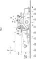
- Fig. 1 is a side view of an asphalt finisher 100 that is an example of a road machine according to an embodiment of the present disclosure.
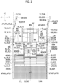
- Fig. 2 is a top view of the asphalt finisher 100.
- the asphalt finisher 100 is a wheel type asphalt finisher and is mainly configured by a tractor 1, a hopper 2, and a screed 3.
- a direction of the hopper 2 viewed from the tractor 1 (+X direction) will be referred to as forward
- a direction of the screed 3 viewed from the tractor 1 (-X direction) will be referred to as rearward.
- the tractor 1 is a mechanism for moving the asphalt finisher 100.
- the tractor 1 rotates a rear wheel 5 using a rear wheel traveling hydraulic motor and rotates a front wheel 6 using a front wheel traveling hydraulic motor to move the asphalt finisher 100.
- the rear wheel traveling hydraulic motor and the front wheel traveling hydraulic motor rotate by receiving supply of a hydraulic oil from a hydraulic pump.
- the front wheel 6 may be a driven wheel.
- the asphalt finisher 100 may be a crawler type asphalt finisher. In this case, a combination of the rear wheel 5 and the front wheel 6 is replaced with a combination of a left crawler and a right crawler.
- the hopper 2 is a mechanism for receiving a paving material PV.
- the hopper 2 is provided in front of the tractor 1 and is configured to be capable of being opened and closed in a vehicle width direction (Y-axis direction) by a hopper cylinder.
- the asphalt finisher 100 usually receives the paving material PV (for example, an asphalt mixture) from a loading platform of a dump truck when the hopper 2 is in a fully open state.
- the dump truck is an example of a transport vehicle that transports the paving material PV.
- Figs. 1 and 2 show that the hopper 2 is in a fully open state.
- a conveyor CV which is at the central portion of the hopper 2 to feed the paving material PV to the rear of the tractor 1.
- the paving material PV fed to the rear of the tractor 1 by the conveyor CV is spread in the vehicle width direction at the rear of the tractor 1 and in front of the screed 3 by the screw SC.
- the screw SC is in a state where a left extension screw SCL and a right extension screw SCR are connected to each other.
- Figs. 1 and 2 omit showing the paving material PV in the hopper 2, show the paving material PV spread by the screw SC in a coarse dot pattern, and show a newly constructed pavement body NP leveled by the screed 3 in a fine dot pattern.
- the screed 3 is a mechanism for leveling the paving material PV.
- the screed 3 includes a front screed 30 and a rear screed 31.
- the front screed 30 includes a left front screed 30L and a right front screed 30R.
- the rear screed 31 is a screed that is capable of expanding and contracting in the vehicle width direction and includes a left rear screed 31L and a right rear screed 31R.
- the rear screed 31 is expanded and contracted by a screed expanding and contracting cylinder 7 provided in the screed 3.
- the screed expanding and contracting cylinder 7 includes a left screed expanding and contracting cylinder 7L and a right screed expanding and contracting cylinder 7R.
- the left rear screed 31L is expanded and contracted by the left screed expanding and contracting cylinder 7L
- the right rear screed 31R is expanded and contracted by the right screed expanding and contracting cylinder 7R.
- the screed 3 is a floating screed pulled by the tractor 1 and is connected to the tractor 1 via a leveling arm 3A.
- the leveling arm 3A includes a left leveling arm 3AL disposed on a left side of the tractor 1 and a right leveling arm 3AR disposed on a right side of the tractor 1.
- An end portion leveling device may be disposed at an end portion of the rear screed 31.
- a side plate 41 is attached to a distal end of the rear screed 31.
- a left side plate 41L is attached to a left end of the left rear screed 31L
- a right side plate 41R is attached to a right end of the right rear screed 31R.
- a tread plate 32 is attached to the rear of the screed 3. Specifically, the tread plate 32 is attached to the rear of the screed 3 such that a worker at the rear of the screed 3 can move back and forth in the vehicle width direction without stepping on the newly constructed pavement body NP.
- the tread plate 32 includes a central tread plate 32C attached to the rear of the front screed 30, a left tread plate 32L attached to the rear of the left rear screed 31L, and a right tread plate 32R attached to the rear of the right rear screed 31R.
- a mold board 42 is attached to a front portion of the screed 3.
- the mold board 42 is configured to be capable of adjusting the amount of the paving material PV staying in front of the screed 3.
- the paving material PV reaches under the screed 3 through a gap between a lower end of the mold board 42 and a roadbed BS.
- the mold board 42 includes a left mold board 42L disposed in front of the left rear screed 31L and a right mold board 42R disposed in front of the right rear screed 31R.
- the screw SC is disposed in front of the mold board 42, and a retaining plate 43 is disposed in front of the screw SC.
- the retaining plate 43 includes a left retaining plate 43L disposed in front of the left extension screw SCL and a right retaining plate 43R disposed in front of the right extension screw SCR.
- the retaining plate 43 may be omitted.
- a traveling speed sensor S1 a controller 50, an object detection device 51, a vehicle-mounted display device 52, a steering device 53, a screed expanding and contracting device 54, an obstacle detection device 55, and an alarm device 56 are attached to the tractor 1.
- the traveling speed sensor S1 is configured to be capable of detecting a traveling speed of the asphalt finisher 100.
- the traveling speed sensor S1 is a wheel speed sensor and is capable of detecting the rotation angular speed and the rotation angle of the rear wheel 5 and the traveling speed and the traveling distance of the asphalt finisher 100.
- the controller 50 is a control device that controls the asphalt finisher 100.
- the controller 50 is configured by a microcomputer including a CPU, a volatile storage device, a non-volatile storage device, and the like.
- Each function of the controller 50 is realized as the CPU executes a program stored in the non-volatile storage device.
- each function of the controller 50 is not only realized by software but may be realized by hardware, or may be realized by a combination of hardware and software.
- the object detection device 51 is an example of an information acquisition device that acquires information of surroundings of the asphalt finisher 100 and is configured to be capable of acquiring information related to a feature within a predetermined range of a road which is a construction target and outputting the acquired information to the controller 50. That is, the object detection device 51 is configured to use the predetermined range of the road which is the construction target as a monitoring target.
- the predetermined range on the road is, for example, a range that is positioned in front of the screed 3 and that includes a boundary line of the road. In the shown example, the predetermined range on the road is a range that has a front-rear width and a right-left width which are larger than the width of a paving mold and for example, is a range of 2 meters square.
- the range positioned in front of the screed 3 is, for example, a range positioned in front of the hopper 2, a range positioned in front of an axle of the front wheel 6, a range positioned in front of an axle of the rear wheel 5, a range positioned in front of the screw SC, and the like.
- the feature within the predetermined range includes, for example, the roadbed BS and an object AP outside the roadbed BS.
- the object AP is a feature used in order to determine the position of an end surface of a laid pavement body in a width direction.
- the object AP is a paving mold that has a predetermined thickness (height) and includes a left object APL on the left side of the asphalt finisher 100 and a right object APR on the right side of the asphalt finisher 100.
- the left object APL includes a first left object APL1 and a second left object APL2
- the right object APR includes a first right object APR1 and a second right object APR2.
- the object AP may be an L-shaped side groove block, a rim stone block, a cutting step portion of an existing pavement body, or the like.
- the cutting step portion of the existing pavement body means a step portion that is formed when an old pavement body is cut and a new pavement body is laid and that is between a surface of a cut portion and a surface of an uncut portion.
- the object AP may be a feature that has almost no thickness, such as a line drawn on the ground, a tape attached to the ground, and a thread stretched along the ground.
- the information related to a feature includes, for example, the height of the feature, the color of the surface of the feature, the reflectance of the surface of the feature, or the like. For the sake of clarity, Fig. 1 omits showing the left object APL.
- the object detection device 51 is a stereo camera configured to be capable of monitoring the predetermined range.
- the object detection device 51 may be a monocular camera, a LIDAR, a millimeter wave radar, a laser radar, a laser scanner, a distance image camera, a laser range finder, an ultrasound sensor, a combination thereof, or the like, which is configured to be capable of monitoring the predetermined range.
- the stereo camera which is the object detection device 51
- the stereo camera is desirably configured to have an automatic exposure adjustment function.
- the object detection device 51 can acquire information related to a feature within the predetermined range, regardless of day or night, that is, without requiring special lighting.
- the object detection device 51 includes a left object detection device 51L provided on the left side of the asphalt finisher 100 and a right object detection device 51R provided on the right side of the asphalt finisher 100.
- the left object detection device 51L is configured to be capable of monitoring the ground on the left side of the asphalt finisher 100.
- the left object detection device 51L is a stereo camera that monitors a left monitoring range ZL (a range surrounded by a one-dot chain line in Fig. 2 ) on the ground on the left side of the asphalt finisher 100.
- the right object detection device 51R is configured to be capable of monitoring the ground on the right side of the asphalt finisher 100.
- the right object detection device 51R is a stereo camera that monitors a right monitoring range ZR (a range surrounded by a one-dot chain line in Fig. 2 ) on the ground on the right side of the asphalt finisher 100.
- the object detection device 51 may be attached to the asphalt finisher 100 via an attachment member 60.
- the attachment member 60 is a member used in order to attach the object detection device 51 to the asphalt finisher 100.
- the attachment member 60 includes a left attachment member 60L and a right attachment member 60R.
- the left object detection device 51L is attached to a left front end portion of the tractor 1 via the left attachment member 60L
- the right object detection device 51R is attached to a right front end portion of the tractor 1 via the right attachment member 60R.
- the left object detection device 51L may be attached to another portion of the asphalt finisher 100, such as a left front end portion of the hopper 2, via the left attachment member 60L.
- the right object detection device 51R may be attached to another portion of the asphalt finisher 100, such as a right front end portion of the hopper 2, via the right attachment member 60R.
- the object detection device 51 may be configured to be capable of monitoring an expansion and contraction state of the rear screed 31.
- the object detection device 51 may additionally include a stereo camera configured to be capable of monitoring an end portion of the left rear screed 31L and a stereo camera configured to be capable of monitoring an end portion of the right rear screed 31R.
- the object detection device 51 may be disposed at the screed 3.
- the object detection device 51 may be disposed at the rear screed 31.
- the object detection device 51 may be disposed at the end portion leveling device.
- the object detection device 51 is attached to the attachment member 60 to face vertically downward in the example shown in Fig. 2 , but may be attached to the attachment member 60 to face another direction such as obliquely downward.
- the left attachment member 60L is configured by an expanding and contracting member TA that is capable of expanding and contracting in the width direction and a pivoting member SB that is pivotably connected to a distal end of the expanding and contracting member TA.
- a pivoting member SBa represented by a broken line in Fig. 2 indicates a state when the pivoting member SB has pivoted. The same applies to the right attachment member 60R.
- the attachment member 60 is configured to be capable of moving a monitoring range of the object detection device 51 with the expanding and contracting member TA and the pivoting member SB. This is to enable response to a change in a pavement width or the like.
- the controller 50 may be configured to control the pivoting of the pivoting member SB such that the object detection device 51 follows the object AP or may be configured to control the expansion and contraction of the expanding and contracting member TA. Accordingly, the controller 50 can continuously include the object AP within the monitoring range of the object detection device 51 even when the position of the object AP changes in the vehicle width direction.
- the attachment member 60 may include at least one of a sensor that detects an expansion and contraction amount of the expanding and contracting member TA and a sensor that detects a pivoting amount (pivoting angle) of the pivoting member SB.
- At least one of the expanding and contracting member TA and the pivoting member SB may be omitted.
- the attachment member 60 may be configured to be incapable of expanding and contracting and to be incapable of pivoting. That is, the attachment member 60 may be a rodshaped member that is incapable of expanding and contracting and that is incapable of pivoting.
- the object detection device 51 may be directly attached to the asphalt finisher 100 without via the attachment member 60.
- the object detection device 51 may be configured to be one device that can simultaneously monitor the ground on the left side of the asphalt finisher 100 and the ground on the right side of the asphalt finisher 100.
- the object detection device 51 may be configured to be one device that can simultaneously monitor the left object APL and the right object APR.
- the object detection device 51 may be attached to a front end central portion of an upper surface of the tractor 1.
- a steering angle sensor configured to be capable of detecting a steering angle of the asphalt finisher 100
- a screed expansion and contraction amount sensor configured to be capable of detecting an expansion and contraction amount of the rear screed 31, and the like may be attached to the asphalt finisher 100.
- the vehicle-mounted display device 52 is configured to be capable of displaying information related to the asphalt finisher 100.
- the vehicle-mounted display device 52 is a liquid crystal display provided in front of a driver's seat 1S.
- the vehicle-mounted display device 52 may include a display device provided at at least one of a left end portion and a right end portion of the screed 3.
- the steering device 53 is configured to be capable of steering the asphalt finisher 100.
- the steering device 53 is configured to expand and contract a front wheel steering cylinder provided close to a front axle.
- the steering device 53 includes a steering electromagnetic control valve that controls the flow rate of a hydraulic oil flowing from the hydraulic pump to the front wheel steering cylinder and the flow rate of the hydraulic oil discharged from the front wheel steering cylinder.
- the steering electromagnetic control valve is configured to control the inflow and outflow of the hydraulic oil in the front wheel steering cylinder in accordance with the rotation of a steering wheel SH (handle), which is a manipulation device.
- the steering electromagnetic control valve may be configured to control the inflow and outflow of the hydraulic oil in the front wheel steering cylinder in response to an operation of an input switch which is a manipulation device different from the steering wheel SH, regardless of the movement of the steering wheel SH.
- the steering electromagnetic control valve may be configured to control the inflow and outflow of the hydraulic oil in the front wheel steering cylinder in accordance with a steering command from the controller 50, regardless of the rotation of the steering wheel SH. That is, the controller 50 may be configured to be capable of automatically steering the asphalt finisher 100 regardless of the presence or absence of an operation of the steering wheel SH by a driver.
- the steering device 53 is configured to control each of a pair of right and left crawlers.
- the crawler type asphalt finisher includes a left operation lever that is a manipulation device for operating the left crawler and a right operation lever that is a manipulation device for operating the right crawler, instead of the steering wheel SH.
- the steering device 53 includes a left steering electromagnetic control valve that controls the flow rate of a hydraulic oil flowing from the hydraulic pump to a left traveling hydraulic motor for rotating the left crawler and a right steering electromagnetic control valve that controls the flow rate of a hydraulic oil flowing from the hydraulic pump to a right traveling hydraulic motor for rotating the right crawler.
- the left steering electromagnetic control valve is configured to control the inflow and outflow of the hydraulic oil in the left traveling hydraulic motor in accordance with a manipulated variable (inclination angle) of the left operation lever.
- the right steering electromagnetic control valve is configured to control the inflow and outflow of the hydraulic oil in the right traveling hydraulic motor in accordance with a manipulated variable (inclination angle) of the right operation lever.
- the screed expansion and contraction control unit 50c is configured to be capable of automatically expanding and contracting the right and left rear screeds 31 that can expand and contract regardless of an operation of a manipulation device such as the expansion and contraction button set.
- the screed expansion and contraction control unit 50c may be configured to be capable of automatically expanding and contracting the rear screed 31 depending on the traveling speed and the steering angle of the asphalt finisher 100 when automatically steering the asphalt finisher 100.
- the coordinates of the predetermined part of the rear screed 31, such as the coordinates of the left front end point of the left rear screed 31L and the coordinates of the right front end point of the right rear screed 31R can be calculated by the coordinate calculation unit 50a.
- the coordinate calculation unit 50a can calculate a relative position of the object detection device 51 with respect to the position of a reference point such as the center point of the tractor 1 based on the expansion and contraction amount of the expanding and contracting member TA performing positioning of the object detection device 51 or the like.
- the coordinate calculation unit 50a can calculate a relative position of each of the point VL, the point VR, the left front end point of the left rear screed 31L, the right front end point of the right rear screed 31R at another time point with respect to the position of the reference point at the first time point.
- the obstacle detection unit 50d is configured to be capable of detecting an obstacle based on an output of the obstacle detection device 55.
- the obstacle detection unit 50d determines whether or not there is an obstacle on the left collision course T1L of the left object detection device 51L based on an output of the left obstacle detection device 55L and determines whether or not there is an obstacle on the right collision course T1R of the right object detection device 51R based on an output of the right obstacle detection device 55R.
- the obstacle detection unit 50d may be configured to calculate a distance between the object detection device 51 (obstacle detection device 55) and the obstacle as a front distance.
- the obstacle detection unit 50d may be configured to calculate a distance between the left object detection device 51L (left obstacle detection device 55L) and the obstacle as a left front distance.
- the obstacle detection unit 50d may be configured to calculate a distance between the right object detection device 51R (right obstacle detection device 55R) and the obstacle as a right front distance.
- the obstacle detection unit 50d may determine that there is a possibility in which the object detection device 51 and an obstacle thereof collide with each other.
- the obstacle detection unit 50d may be configured not to determine that there is a possibility in which the object detection device 51 and the obstacle thereof collide with each other. That is, in this case, the obstacle detection unit 50d may determine that there is no possibility of collision.
- the predetermined value FD may be a value registered in advance or may be a value dynamically set.
- the predetermined value FD is a value stored in advance in the non-volatile storage device and is larger than a distance between the object detection device 51 and a front end of the asphalt finisher 100 in a direction along the front-rear axis AX.
- the predetermined value FD may be a value that is equal to or smaller than the distance between the object detection device 51 and the front end of the asphalt finisher 100 in the direction along the front-rear axis AX.
- the predetermined value FD may be dynamically set based on at least one of design data stored in advance in the volatile storage device or the non-volatile storage device and the traveling speed of the asphalt finisher 100.
- the obstacle detection unit 50d may set the predetermined value FD based on at least one of a curvature radius, a slope, and the like of a road derived from the design data.
- the obstacle detection unit 50d may set the predetermined value FD based on the traveling speed of the asphalt finisher 100.
- the obstacle detection unit 50d may determine whether or not there is a possibility in which the object detection device 51 and an obstacle thereof collide with each other, using at least one of a curvature radius, a slope, and the like of a road derived from a front distance and design data.
- the obstacle detection unit 50d may be configured to output an alarm start command to the alarm device 56 in a case where it is determined that there is an obstacle on the collision course T1 of the object detection device 51.
- the alarm device 56 that has received the alarm start command may be configured to output at least one of a visual alarm and an audible alarm.
- the obstacle detection unit 50d may be configured to output an alarm start command to the alarm device 56 in a case where it is determined that there is a possibility in which the object detection device 51 and an obstacle thereof collide with each other.
- the obstacle detection unit 50d may make content of an alarm output in a case where it is determined that there is an obstacle on the collision course T1 of the object detection device 51 and content of an alarm output in a case where it is determined that there is a possibility in which the object detection device 51 and an obstacle thereof collide with each other different from each other.
- the obstacle detection unit 50d may be configured not to output an alarm start command to the alarm device 56 until it is determined that there is a possibility in which the object detection device 51 and an obstacle thereof collide with each other even in a case where it is determined that there is the obstacle on the collision course T1 of the object detection device 51.
- the obstacle detection unit 50d may be configured to stop an output of an alarm when a predetermined release operation by the operator is performed or when the obstacle detection device 55 no longer detects an obstacle after the output of the alarm is started.
- the predetermined release operation is an operation of an alarm release button (not shown) that is a manipulation device provided close to the vehicle-mounted display device 52.
- the obstacle detection unit 50d may be configured to output an alarm stop command to the alarm device 56 in a case where it is determined that the alarm release button is operated or a case where it is determined that there is no obstacle on the collision course T1 of the object detection device 51 after an output of an alarm is started.
- the obstacle detection unit 50d may be configured not to stop an output of an alarm until it is determined that the alarm release button is operated even in a case where it is determined that there is no obstacle on the collision course T1 of the object detection device 51.
- the obstacle detection unit 50d may move the object detection device 51 by operating at least one of the pivoting member SB and the expanding and contracting member TA which configure the attachment member 60 in a case where it is determined that there is a possibility in which the object detection device 51 and an obstacle thereof collide with each other. This is to avoid collision between the obstacle and the object detection device 51.
- the obstacle detection unit 50d may bring back the object detection device 51 to an original position by operating at least one of the pivoting member SB and the expanding and contracting member TA in a case where it is determined that there is no possibility in which the object detection device 51 and the obstacle thereof collide with each other, that is, a case where the object detection device 51 has passed through the obstacle thereof.
- the obstacle detection unit 50d may decelerate the asphalt finisher 100 and may stop the asphalt finisher 100 in a case where it is determined that there is a possibility in which the object detection device 51 and an obstacle thereof collide with each other.
- Fig. 5 is a flowchart showing an example of a flow of the target setting processing.
- the controller 50 repeatedly executes the target setting processing in a predetermined control cycle.
- the controller 50 acquires vehicle body coordinates (Step ST1).
- the vehicle body coordinates mean coordinates of a predetermined part of the asphalt finisher 100 and includes coordinates of a predetermined part of the rear screed 31 such as coordinates of the left front end point of the left rear screed 31L and coordinates of the right front end point of the right rear screed 31R.
- the controller 50 stores the center point of the asphalt finisher 100 at the first time point such as a construction start time point as a reference point.
- the controller 50 can derive a relative position of the center point of the asphalt finisher 100 and a direction of the asphalt finisher 100 at any time point such as the present time point based on outputs of the traveling speed sensor S1 and the steering angle sensor.
- the relative position of the center point means a relative position of the center point with respect to the reference point. The same applies to the following description.
- the controller 50 can derive coordinates of a turning center based on the output of the steering angle sensor. Then, the controller 50 can derive the relative position of the center point of the asphalt finisher 100 and the direction of the asphalt finisher 100 at any time point such as the present time point based on the coordinates of the turning center and the output of the traveling speed sensor S1.
- the controller 50 may be configured to derive a moving distance, a change in a posture, or the like based on an output of an inertial measurement unit (IMU), a global navigation satellite system (GNSS), a surveying instrument, or the like (not shown) mounted on the asphalt finisher 100.
- IMU inertial measurement unit
- GNSS global navigation satellite system
- surveying instrument or the like (not shown) mounted on the asphalt finisher 100.
- the controller 50 can derive a relative position of the predetermined part of the asphalt finisher 100 based on the relative position of the center point of the asphalt finisher 100 and the direction of the asphalt finisher 100 at any time point, a known dimension of each of members configuring the asphalt finisher 100, or the like.
- the relative position of the predetermined part of the asphalt finisher 100 includes a relative position of the left object detection device 51L and a relative position of the right object detection device 51R.
- the controller 50 acquires feature coordinates (Step ST2).
- the feature coordinates mean coordinates of a feature such as the object AP and includes coordinates on a boundary line of a road, which is a construction target, on the left side, coordinates on a boundary line of the road, which is the construction target, on the right side, and the like.
- the controller 50 can calculate coordinates of the point VL that are coordinates on the boundary line of the road, which is the construction target, on the left side and coordinates of the point VR0 that are coordinates on the boundary line of the road, which is the construction target, on the right side based on the relative position of the center point of the asphalt finisher 100 and the direction of the asphalt finisher 100 at any time point and an output of the object detection device 51 at any time point.
- the controller 50 After acquiring the vehicle body coordinates and the feature coordinates, the controller 50 sets a target (Step ST3). In the shown example, the controller 50 calculates a target value of an expansion and contraction amount of the rear screed 31.
- the controller 50 derives a distance between the point VL that is at a closest position in front of a predetermined part (for example, the left front end point) of the left rear screed 31L and the front-rear axis AX that is a center axis of the asphalt finisher 100 (hereinafter, referred to as a "first distance") based on the relative position of the center point of the asphalt finisher 100 and the direction of the asphalt finisher 100 at the present time point.
- a predetermined part for example, the left front end point
- AX that is a center axis of the asphalt finisher 100
- the controller 50 derives a distance between the predetermined part (for example, the left front end point) of the left rear screed 31L and the front-rear axis AX of the asphalt finisher 100 (hereinafter, referred to as a "second distance") based on the relative position of the center point of the asphalt finisher 100 and the direction of the asphalt finisher 100 at the present time point. Then, the controller 50 sets a difference between the first distance and the second distance as a target expansion and contraction amount.
- the controller 50 sets the difference between the first distance and the second distance as a target expansion amount in a case where the first distance is larger than the second distance and sets the difference between the first distance and the second distance as a target contraction amount in a case where the first distance is smaller than the second distance.
- the controller 50 determines an expansion and contraction speed based on a distance between the predetermined part (for example, the left front end point) of the left rear screed 31L and the point VL that is at a closest position in front thereof in a traveling direction (hereinafter, referred to as a "third distance"). Specifically, the controller 50 increases the expansion and contraction speed as the third distance increases when the target expansion and contraction amount is the same.
- the controller 50 may estimate the position of the predetermined part (for example, the left front end point) of the left rear screed 31L after a predetermined time (for example, 1 second later) and derive a line segment that connects the closest point VL in front of the position of the predetermined part after the predetermined time and the closest point VL at the rear thereof to each other. Then, the controller 50 may use a distance between an interpolation point on the line segment (a point interpolating two points VL) and the front-rear axis AX as the first distance.
- a predetermined time for example, 1 second later
- the controller 50 can identify the position of the boundary line in front of the screed 3, the rear screed 31 can be expanded and contracted at an appropriate timing without excess or deficiency. For this reason, since the controller 50 can suppress or prevent the expansion and contraction of the rear screed 31 from being delayed in a case where a construction width changes, construction accuracy can be improved.
- the screed expansion and contraction control unit 50c can expand and contract the left rear screed 31L such that the coordinates of the left front end point of the left rear screed 31L match coordinates on the guide line GD when the asphalt finisher 100 has advanced by a predetermined distance. That is, the screed expansion and contraction control unit 50c can control the expansion and contraction amount of the left rear screed 31L such that also a distance between the point VL and the left front end point of the left rear screed 31L in the vehicle width direction becomes zero when a distance between the point VL and the left front end point of the left rear screed 31L in the traveling direction at any time point becomes zero.
- the screed expansion and contraction control unit 50c can expand and contract the right rear screed 31R such that the coordinates of the right front end point of the right rear screed 31R match coordinates of the nearest point VR in front thereof when the asphalt finisher 100 has advanced by a predetermined distance. That is, the screed expansion and contraction control unit 50c can control the expansion and contraction amount of the right rear screed 31R such that also a distance between the point VR and the right front end point of the right rear screed 31R in the vehicle width direction becomes zero when a distance between the point VR and the right front end point of the right rear screed 31R in the traveling direction at any time point becomes zero.
- Fig. 6 is a flowchart showing an example of a flow of the alarm processing.
- the controller 50 repeatedly executes the alarm processing in a predetermined control cycle while the asphalt finisher 100 advances.
- the controller 50 determines whether or not there is an obstacle on the collision course of the information acquisition device (Step ST11).
- the obstacle detection unit 50d of the controller 50 determines whether or not there is an obstacle on the collision course T1 of the object detection device 51 based on an output of the object detection device 51 that is an example of the information acquisition device.
- the controller 50 may identify the position and the height of the detected obstacle. Then, in a case where the height of the identified obstacle is larger than the height of the object detection device 51, the controller 50 may determine that there is no obstacle since there is no possibility of collision.
- the controller 50 may specify the position of the obstacle as coordinates based on a distance from the obstacle detection device 55.
- the controller 50 may store the position of the detected obstacle on an electronic construction drawing.
- Step ST12 the controller 50 outputs an alarm (Step ST12).
- the obstacle detection unit 50d outputs an alarm start command to the alarm device 56, and an output of an alarm by the alarm device 56 is started.
- Step ST13 the controller 50 stops an output of an alarm (Step ST13).
- the obstacle detection unit 50d ends this time of alarm processing without outputting an alarm start command to the alarm device 56.
- the obstacle detection unit 50d outputs an alarm stop command to the alarm device 56 and stops the output of the alarm by the alarm device 56.
- the controller 50 may stop an output of an alarm regardless of whether or not there is an obstacle on the collision course of the information acquisition device.
- the controller 50 can notify the operator of the asphalt finisher 100 and the worker working in the surroundings of the asphalt finisher 100 of the fact that there is an obstacle on the collision course of the information acquisition device.
- the controller 50 may be configured to output an alarm in a case where it is determined that there is a possibility in which the information acquisition device and an obstacle thereof collide with each other.
- the controller 50 may make content of an alarm different when outputting an alarm in each of a case where it is determined that there is an obstacle on the collision course of the information acquisition device and a case where it is determined that there is a possibility in which the information acquisition device and an obstacle thereof collide with each other.
- the controller 50 can notify the operator of the asphalt finisher 100 and the worker working in the surroundings of the asphalt finisher 100 of the fact that there is a possibility in which the information acquisition device and an obstacle thereof collide with each other.
- the asphalt finisher 100 that is an example of the road machine according to the embodiment of the present disclosure includes the tractor 1, the hopper 2 which is provided in front of the tractor 1 and which receives the paving material PV, the conveyor CV which feeds the paving material PV in the hopper 2 to the rear of the tractor 1, the screw SC which spreads the paving material PV fed by the conveyor CV at the rear of the tractor 1, the screed 3 which levels the paving material PV spread by the screw SC at the rear of the screw SC, and the control device (controller 50) that calculates coordinates on the boundary line (guide line GD) in a predetermined coordinate system based on information related to a feature (object AP) that defines the boundary line (guide line GD) of the construction target range positioned in front of the screed 3.
- the control device controller 50
- the controller 50 can recognize a change in a direction of the boundary line (guide line GD) before the screed 3 reaches a portion where the direction of the boundary line (guide line GD) changes. For this reason, the controller 50 can appropriately control the expansion and contraction amount of the screed 3 compared to a case where the screed is expanded and contracted such that an interval existing between the end portion of the screed 3 and the boundary line (guide line GD) is recognized and then the interval is decreased. In other words, the controller 50 can suppress the generation of the interval between the end portion of the screed 3 and the boundary line (guide line GD).
- the configuration has an effect in which it can be suppressed that a calculation load related to calculation of coordinates becomes needlessly high.
- controller 50 is configured to expand and contract the screed 3 such that coordinates on the boundary line (guide line GD) calculated at the first time point become target coordinates of the end portion of the screed 3 at the second time point after the first time point.
- the controller 50 can recognize a change in a direction of the boundary line (guide line GD) before the screed 3 reaches a portion where the direction of the boundary line (guide line GD) changes. For this reason, the configuration has an effect in which the expansion and contraction amount of the screed 3 can be more appropriately controlled.
- the asphalt finisher 100 may include the object detection device 51 that acquires information related to the feature (object AP) which defines the boundary line (guide line GD) of the road, which is the construction target positioned in front of the screed 3.
- the object detection device 51 may be disposed in front of the screed 3. In the example shown in Fig. 2 , the object detection device 51 is disposed in front of the tractor 1 which is in front of the screed 3.
- the object detection device 51 can acquire information related to the portion where the direction of the boundary line (guide line GD) changes (for example, a relative position with respect to the vehicle body (tractor 1), a distance image, an image, or the like) before the screed 3 reaches the portion. For this reason, the configuration has an effect in which the controller 50 can recognize a change in the direction of the boundary line (guide line GD) before the screed 3 reaches the portion where the direction of the boundary line (guide line GD) changes.
- the asphalt finisher 100 that is an example of the road machine according to the embodiment of the present disclosure includes the tractor 1, the hopper 2 which is provided in front of the tractor 1 and which receives a paving material, the conveyor CV which feeds the paving material PV in the hopper 2 to the rear of the tractor 1, the screw SC which spreads the paving material PV fed by the conveyor CV at the rear of the tractor 1, the screed 3 which levels the paving material PV spread by the screw SC at the rear of the screw SC and which can expand and contract in the vehicle width direction, the object detection device 51 which is an example of the information acquisition device, which is disposed out of a range of a width WC of the tractor 1 and which acquires information of the surroundings, and the obstacle detection device 55 which detects an obstacle on the collision course of the object detection device 51. Out of the range of the width WC of the tractor 1 may be out of a range of the width of the hopper 2 in a fully open state.
- the asphalt finisher 100 can recognize the presence of an obstacle having a possibility of colliding with the information acquisition device attached to protrude from the width WC of the tractor 1 in the vehicle width direction beforehand. For this reason, the asphalt finisher 100 can suppress or prevent the information acquisition device from hitting the obstacle during construction.
- the asphalt finisher 100 may be configured to be capable of notifying surroundings of detection of an obstacle by the obstacle detection device 55.
- the asphalt finisher 100 can notify the operator of the asphalt finisher 100, the worker working in the surroundings of the asphalt finisher 100, or the like of the fact that there is an obstacle on the collision course of the information acquisition device. For this reason, the asphalt finisher 100 can suppress or prevent the information acquisition device from hitting the obstacle during construction.
- the asphalt finisher 100 may include the controller 50 that is an example of the control device.
- the obstacle detection device 55 may be configured to detect an obstacle positioned in a predetermined space.
- the controller 50 may be configured to operate the alarm device 56 that is an example of an output device and to notify surroundings of the fact that the obstacle is in the collision course.
- the obstacle detection device 55 includes the left obstacle detection device 55L and the right obstacle detection device 55R.
- a predetermined space related to the left obstacle detection device 55L is, for example, a rectangular parallelepiped space of which a width is a distance WDL between a left end of the tractor 1 and a left end of the left object detection device 51L in the vehicle width direction (see Fig. 2 ) and of which a height is a distance HT between the roadbed BS and an upper end of the left object detection device 51L in a direction perpendicular to each of the vehicle width direction and the traveling direction (see Fig. 1 ).
- a predetermined space related to the right obstacle detection device 55R is, for example, a rectangular parallelepiped space of which a width is a distance WDR between a right end of the tractor 1 and a right end of the right object detection device 51R in the vehicle width direction (see Fig. 2 ) and of which a height is a distance between the roadbed BS and an upper end of the right object detection device 51R in the direction perpendicular to each of the vehicle width direction and the traveling direction.
- the asphalt finisher 100 may include the alarm device 56 that outputs an alarm.
- the alarm device 56 may be configured to output an alarm when the obstacle detection device 55 detects an obstacle and to stop the output of the alarm when a release operation by the operator is performed or when the obstacle detection device 55 no longer detects an obstacle.
- the controller 50 can output an alarm in an appropriate situation and can improve reliability of the alarm. For this reason, the controller 50 can more reliably prevent the information acquisition device from hitting an obstacle during construction.
- the controller 50 specifies the position of an obstacle through coordinates in the embodiment, the coordinates may not necessarily be used.
- the controller 50 can recognize a positional relationship between the object detection device 51 of the asphalt finisher 100 and the obstacle based on a distance from the obstacle detection device 55 to the obstacle. Accordingly, the controller 50 can avoid contact between the object detection device 51 and the obstacle.
- the object detection device 51 is configured to acquire information related to a feature (object AP) which defines the boundary line (guide line GD) of the construction target range positioned in front of the screed 3.
- the controller 50 may be configured to acquire information related to a feature (object AP) from design data stored in advance in the volatile storage device or the non-volatile storage device. In this case, acquisition of the information related to a feature (object AP) by the object detection device 51 may be omitted.
- the object detection device 51 is attached to the asphalt finisher 100 in the embodiment described above, but may be attached to a moving body other than the asphalt finisher 100 such as a vehicle and a multicopter.
- the information acquisition device is the object detection device 51 configured to acquire information related to a feature that is in a predetermined range of the road which is the construction target in the embodiment described above
- the information acquisition device may be another device such as a camera that captures an image of a space to the left of a left hopper wing in a blind spot when viewed from the driver's seat.
Landscapes
- Engineering & Computer Science (AREA)
- Multimedia (AREA)
- Signal Processing (AREA)
- Architecture (AREA)
- Civil Engineering (AREA)
- Structural Engineering (AREA)
- Physics & Mathematics (AREA)
- General Physics & Mathematics (AREA)
- Business, Economics & Management (AREA)
- Emergency Management (AREA)
- Road Paving Machines (AREA)
Claims (4)
- Straßenbaumaschine (100), umfassend:einen Traktor (1);einen Trichter (2), der vor dem Traktor (1) vorgesehen ist und der angepasst ist, ein Straßendeckenmaterial (PV) zu empfangen;einen Förderer (CV), der angepasst ist, das Straßendeckenmaterial (PV) in dem Trichter (2) zu einer Rückseite des Traktors (1) zu fördern;eine Schnecke (SC), die angepasst ist, das von dem Förderer (CV) zu der Rückseite des Traktors (1) geförderte Straßendeckenmaterial (PV) zu verteilen;eine Bohle (3), die angepasst ist, das von der Schnecke (SC) an einer Rückseite der Schnecke (SC) verteilte Straßendeckenmaterial (PV) zu nivellieren und die in der Lage ist, sich in einer Fahrzeugbreitenrichtung zu erweitern und zusammenzuziehen;eine Informationserfassungsvorrichtung, die außerhalb eines Bereichs einer Breite (WC) des Traktors (1) angeordnet ist und die angepasst ist, Informationen von Umgebungen zu erfassen, und eine Objektdetektionsvorrichtung (51) oder eine Kamera umfasst; und gekennzeichnet ist durcheine Hindernisdetektionsvorrichtung (55), die angepasst ist, ein Hindernis auf einem Kollisionskurs (T1) der Informationserfassungsvorrichtung zu detektieren.
- Straßenfertigungsmaschine (100) nach Anspruch 1,
wobei die Hindernisdetektionsvorrichtung (55) angepasst ist, Umgebungen über eine Detektion des Hindernisses zu benachrichtigen. - Straßenfertigungsmaschine (100) nach Anspruch 1 oder 2, ferner umfassend:eine Steuervorrichtung (50),wobei die Hindernisdetektionsvorrichtung (55) angepasst ist, das Hindernis zu detektieren, das in einem rechtwinkligen Parallelepiped-Raum positioniert ist, dessen eine Breite ein Abstand (WDL, WDR) zwischen dem Traktor (1) und einem distalen Ende der Informationserfassungsvorrichtung in der Fahrzeugbreitenrichtung ist und dessen eine Höhe ein Abstand (HT) zwischen einem Straßenbett (BS) und einem oberen Ende der Informationserfassungsvorrichtung in einer Richtung senkrecht zu jeder der Fahrzeugbreitenrichtung und einer Fahrtrichtung ist, undin einem Fall, bei dem bestimmt wird, dass sich das von der Hindernisdetektionsvorrichtung (55) detektierte Hindernis auf dem Kollisionskurs (T1) der Informationserfassungsvorrichtung befindet, die Steuervorrichtung (50) angepasst ist, eine Ausgabevorrichtung (56) zu betätigen und Umgebungen dadurch über eine Tatsache zu benachrichtigen, dass sich das Hindernis auf dem Kollisionskurs (T1) befindet.
- Straßenfertigungsmaschine (100) nach Anspruch 1 oder 2, ferner umfassend:eine Alarmvorrichtung (56), die angepasst ist, einen Alarm auszugeben,wobei die Alarmvorrichtung (56) den Alarm ausgibt, wenn die Hindernisdetektionsvorrichtung (55) das Hindernis detektiert, und die Ausgabe des Alarms stoppt, wenn ein Freigabevorgang durch einen Bediener durchgeführt wird oder wenn die Hindernisdetektionsvorrichtung (55) das Hindernis nicht mehr detektiert.
Applications Claiming Priority (1)
| Application Number | Priority Date | Filing Date | Title |
|---|---|---|---|
| JP2022064599A JP7740801B2 (ja) | 2022-04-08 | 2022-04-08 | 道路機械 |
Publications (2)
| Publication Number | Publication Date |
|---|---|
| EP4257746A1 EP4257746A1 (de) | 2023-10-11 |
| EP4257746B1 true EP4257746B1 (de) | 2024-12-11 |
Family
ID=85979765
Family Applications (1)
| Application Number | Title | Priority Date | Filing Date |
|---|---|---|---|
| EP23166662.9A Active EP4257746B1 (de) | 2022-04-08 | 2023-04-05 | Strassenfertiger |
Country Status (3)
| Country | Link |
|---|---|
| EP (1) | EP4257746B1 (de) |
| JP (1) | JP7740801B2 (de) |
| CN (1) | CN116892151A (de) |
Family Cites Families (11)
| Publication number | Priority date | Publication date | Assignee | Title |
|---|---|---|---|---|
| US5484227A (en) * | 1993-04-09 | 1996-01-16 | Niigata Engineering Co., Ltd. | Control device for asphalt finisher |
| JP6672300B2 (ja) * | 2015-07-15 | 2020-03-25 | 住友建機株式会社 | アスファルトフィニッシャ |
| EP3276079B1 (de) * | 2016-07-26 | 2021-07-14 | Caterpillar Paving Products Inc. | Steuerungssystem für einen strassenfertiger |
| JP6896525B2 (ja) | 2017-06-28 | 2021-06-30 | 住友建機株式会社 | アスファルトフィニッシャ |
| WO2019009349A1 (ja) * | 2017-07-05 | 2019-01-10 | 住友建機株式会社 | アスファルトフィニッシャ |
| EP3666977B1 (de) * | 2017-08-08 | 2023-12-13 | Sumitomo (S.H.I.) Construction Machinery Co., Ltd. | Strassenmaschine |
| JP6910316B2 (ja) * | 2018-03-13 | 2021-07-28 | 株式会社三井E&Sマシナリー | クレーン運転補助システムおよびクレーン運転補助方法 |
| WO2020196539A1 (ja) * | 2019-03-25 | 2020-10-01 | 住友建機株式会社 | アスファルトフィニッシャ |
| JP7374601B2 (ja) * | 2019-03-25 | 2023-11-07 | 住友建機株式会社 | アスファルトフィニッシャ |
| WO2020235099A1 (ja) * | 2019-05-23 | 2020-11-26 | 株式会社島津製作所 | X線撮影装置およびx線撮影装置の使用方法 |
| US20230105732A1 (en) * | 2021-09-20 | 2023-04-06 | Caterpillar Paving Products Inc. | Control system for a paving machine |
-
2022
- 2022-04-08 JP JP2022064599A patent/JP7740801B2/ja active Active
-
2023
- 2023-04-05 EP EP23166662.9A patent/EP4257746B1/de active Active
- 2023-04-07 CN CN202310363420.5A patent/CN116892151A/zh active Pending
Also Published As
| Publication number | Publication date |
|---|---|
| EP4257746A1 (de) | 2023-10-11 |
| CN116892151A (zh) | 2023-10-17 |
| JP2023154943A (ja) | 2023-10-20 |
| JP7740801B2 (ja) | 2025-09-17 |
Similar Documents
| Publication | Publication Date | Title |
|---|---|---|
| US12139881B2 (en) | Work machine control system, work machine, and work machine control method | |
| CN111373338A (zh) | 用于操作移动系统的方法和设备 | |
| US11142890B2 (en) | System and method of soil management for an implement | |
| CN112424427B (zh) | 作业机械的控制装置及控制方法 | |
| EP4130383B1 (de) | Asphaltfertiger | |
| US12085950B2 (en) | Visual overlays for providing perception of depth | |
| JP2020197045A (ja) | 表示システムおよび表示方法 | |
| EP4257747B1 (de) | Steuerungssystem für einen strassenfertiger | |
| EP4257748B1 (de) | Steuerungssystem für einen strassenfertiger | |
| EP4257746A1 (de) | Strassenfertiger | |
| JP2019049461A (ja) | 作業機械の計測システム、作業機械、及び作業機械の計測方法 | |
| US20200156425A1 (en) | Hitch assistance system with interface presenting simplified path image | |
| JP7799965B2 (ja) | 道路機械 | |
| JP7793883B2 (ja) | 道路機械 | |
| WO2024070557A1 (ja) | 作業現場の検出システム及び作業現場の検出方法 | |
| EP4579038A1 (de) | Strassenpflasterungsmaschine | |
| EP4286588A1 (de) | Strassenfertiger | |
| KR101855988B1 (ko) | 지형측정시스템 및 그것을 구비한 건설기계 | |
| JP7646976B2 (ja) | アスファルトフィニッシャ、及びアスファルトフィニッシャの施工支援システム | |
| CA3118562C (en) | A system and method for generating images based on work machine traveling state | |
| JP2025100037A (ja) | 道路機械 | |
| US11607987B1 (en) | Multi-functional headlamp and image projector | |
| WO2024070520A1 (ja) | 作業機械の制御システム及び作業機械の制御方法 | |
| WO2024070519A1 (ja) | 作業機械の制御システム及び作業機械の制御方法 |
Legal Events
| Date | Code | Title | Description |
|---|---|---|---|
| PUAI | Public reference made under article 153(3) epc to a published international application that has entered the european phase |
Free format text: ORIGINAL CODE: 0009012 |
|
| STAA | Information on the status of an ep patent application or granted ep patent |
Free format text: STATUS: EXAMINATION IS IN PROGRESS |
|
| 17P | Request for examination filed |
Effective date: 20230405 |
|
| AK | Designated contracting states |
Kind code of ref document: A1 Designated state(s): AL AT BE BG CH CY CZ DE DK EE ES FI FR GB GR HR HU IE IS IT LI LT LU LV MC ME MK MT NL NO PL PT RO RS SE SI SK SM TR |
|
| GRAP | Despatch of communication of intention to grant a patent |
Free format text: ORIGINAL CODE: EPIDOSNIGR1 |
|
| STAA | Information on the status of an ep patent application or granted ep patent |
Free format text: STATUS: GRANT OF PATENT IS INTENDED |
|
| INTG | Intention to grant announced |
Effective date: 20240710 |
|
| GRAS | Grant fee paid |
Free format text: ORIGINAL CODE: EPIDOSNIGR3 |
|
| GRAA | (expected) grant |
Free format text: ORIGINAL CODE: 0009210 |
|
| STAA | Information on the status of an ep patent application or granted ep patent |
Free format text: STATUS: THE PATENT HAS BEEN GRANTED |
|
| AK | Designated contracting states |
Kind code of ref document: B1 Designated state(s): AL AT BE BG CH CY CZ DE DK EE ES FI FR GB GR HR HU IE IS IT LI LT LU LV MC ME MK MT NL NO PL PT RO RS SE SI SK SM TR |
|
| REG | Reference to a national code |
Ref country code: GB Ref legal event code: FG4D |
|
| REG | Reference to a national code |
Ref country code: CH Ref legal event code: EP |
|
| REG | Reference to a national code |
Ref country code: DE Ref legal event code: R096 Ref document number: 602023001303 Country of ref document: DE |
|
| REG | Reference to a national code |
Ref country code: IE Ref legal event code: FG4D |
|
| REG | Reference to a national code |
Ref country code: LT Ref legal event code: MG9D |
|
| PG25 | Lapsed in a contracting state [announced via postgrant information from national office to epo] |
Ref country code: HR Free format text: LAPSE BECAUSE OF FAILURE TO SUBMIT A TRANSLATION OF THE DESCRIPTION OR TO PAY THE FEE WITHIN THE PRESCRIBED TIME-LIMIT Effective date: 20241211 |
|
| PG25 | Lapsed in a contracting state [announced via postgrant information from national office to epo] |
Ref country code: FI Free format text: LAPSE BECAUSE OF FAILURE TO SUBMIT A TRANSLATION OF THE DESCRIPTION OR TO PAY THE FEE WITHIN THE PRESCRIBED TIME-LIMIT Effective date: 20241211 |
|
| PG25 | Lapsed in a contracting state [announced via postgrant information from national office to epo] |
Ref country code: BG Free format text: LAPSE BECAUSE OF FAILURE TO SUBMIT A TRANSLATION OF THE DESCRIPTION OR TO PAY THE FEE WITHIN THE PRESCRIBED TIME-LIMIT Effective date: 20241211 |
|
| REG | Reference to a national code |
Ref country code: NL Ref legal event code: MP Effective date: 20241211 |
|
| PG25 | Lapsed in a contracting state [announced via postgrant information from national office to epo] |
Ref country code: ES Free format text: LAPSE BECAUSE OF FAILURE TO SUBMIT A TRANSLATION OF THE DESCRIPTION OR TO PAY THE FEE WITHIN THE PRESCRIBED TIME-LIMIT Effective date: 20241211 |
|
| PG25 | Lapsed in a contracting state [announced via postgrant information from national office to epo] |
Ref country code: NO Free format text: LAPSE BECAUSE OF FAILURE TO SUBMIT A TRANSLATION OF THE DESCRIPTION OR TO PAY THE FEE WITHIN THE PRESCRIBED TIME-LIMIT Effective date: 20250311 |
|
| PG25 | Lapsed in a contracting state [announced via postgrant information from national office to epo] |
Ref country code: LV Free format text: LAPSE BECAUSE OF FAILURE TO SUBMIT A TRANSLATION OF THE DESCRIPTION OR TO PAY THE FEE WITHIN THE PRESCRIBED TIME-LIMIT Effective date: 20241211 Ref country code: GR Free format text: LAPSE BECAUSE OF FAILURE TO SUBMIT A TRANSLATION OF THE DESCRIPTION OR TO PAY THE FEE WITHIN THE PRESCRIBED TIME-LIMIT Effective date: 20250312 |
|
| PG25 | Lapsed in a contracting state [announced via postgrant information from national office to epo] |
Ref country code: RS Free format text: LAPSE BECAUSE OF FAILURE TO SUBMIT A TRANSLATION OF THE DESCRIPTION OR TO PAY THE FEE WITHIN THE PRESCRIBED TIME-LIMIT Effective date: 20250311 |
|
| PG25 | Lapsed in a contracting state [announced via postgrant information from national office to epo] |
Ref country code: NL Free format text: LAPSE BECAUSE OF FAILURE TO SUBMIT A TRANSLATION OF THE DESCRIPTION OR TO PAY THE FEE WITHIN THE PRESCRIBED TIME-LIMIT Effective date: 20241211 |
|
| REG | Reference to a national code |
Ref country code: AT Ref legal event code: MK05 Ref document number: 1750471 Country of ref document: AT Kind code of ref document: T Effective date: 20241211 |
|
| PG25 | Lapsed in a contracting state [announced via postgrant information from national office to epo] |
Ref country code: SM Free format text: LAPSE BECAUSE OF FAILURE TO SUBMIT A TRANSLATION OF THE DESCRIPTION OR TO PAY THE FEE WITHIN THE PRESCRIBED TIME-LIMIT Effective date: 20241211 |
|
| PG25 | Lapsed in a contracting state [announced via postgrant information from national office to epo] |
Ref country code: PL Free format text: LAPSE BECAUSE OF FAILURE TO SUBMIT A TRANSLATION OF THE DESCRIPTION OR TO PAY THE FEE WITHIN THE PRESCRIBED TIME-LIMIT Effective date: 20241211 |
|
| PGFP | Annual fee paid to national office [announced via postgrant information from national office to epo] |
Ref country code: DE Payment date: 20250224 Year of fee payment: 3 |
|
| PG25 | Lapsed in a contracting state [announced via postgrant information from national office to epo] |
Ref country code: IS Free format text: LAPSE BECAUSE OF FAILURE TO SUBMIT A TRANSLATION OF THE DESCRIPTION OR TO PAY THE FEE WITHIN THE PRESCRIBED TIME-LIMIT Effective date: 20250411 |
|
| PG25 | Lapsed in a contracting state [announced via postgrant information from national office to epo] |
Ref country code: PT Free format text: LAPSE BECAUSE OF FAILURE TO SUBMIT A TRANSLATION OF THE DESCRIPTION OR TO PAY THE FEE WITHIN THE PRESCRIBED TIME-LIMIT Effective date: 20250411 |
|
| PG25 | Lapsed in a contracting state [announced via postgrant information from national office to epo] |
Ref country code: EE Free format text: LAPSE BECAUSE OF FAILURE TO SUBMIT A TRANSLATION OF THE DESCRIPTION OR TO PAY THE FEE WITHIN THE PRESCRIBED TIME-LIMIT Effective date: 20241211 |
|
| PG25 | Lapsed in a contracting state [announced via postgrant information from national office to epo] |
Ref country code: RO Free format text: LAPSE BECAUSE OF FAILURE TO SUBMIT A TRANSLATION OF THE DESCRIPTION OR TO PAY THE FEE WITHIN THE PRESCRIBED TIME-LIMIT Effective date: 20241211 Ref country code: AT Free format text: LAPSE BECAUSE OF FAILURE TO SUBMIT A TRANSLATION OF THE DESCRIPTION OR TO PAY THE FEE WITHIN THE PRESCRIBED TIME-LIMIT Effective date: 20241211 |
|
| PG25 | Lapsed in a contracting state [announced via postgrant information from national office to epo] |
Ref country code: SK Free format text: LAPSE BECAUSE OF FAILURE TO SUBMIT A TRANSLATION OF THE DESCRIPTION OR TO PAY THE FEE WITHIN THE PRESCRIBED TIME-LIMIT Effective date: 20241211 |
|
| PG25 | Lapsed in a contracting state [announced via postgrant information from national office to epo] |
Ref country code: CZ Free format text: LAPSE BECAUSE OF FAILURE TO SUBMIT A TRANSLATION OF THE DESCRIPTION OR TO PAY THE FEE WITHIN THE PRESCRIBED TIME-LIMIT Effective date: 20241211 |
|
| PG25 | Lapsed in a contracting state [announced via postgrant information from national office to epo] |
Ref country code: IT Free format text: LAPSE BECAUSE OF FAILURE TO SUBMIT A TRANSLATION OF THE DESCRIPTION OR TO PAY THE FEE WITHIN THE PRESCRIBED TIME-LIMIT Effective date: 20241211 |
|
| PG25 | Lapsed in a contracting state [announced via postgrant information from national office to epo] |
Ref country code: SE Free format text: LAPSE BECAUSE OF FAILURE TO SUBMIT A TRANSLATION OF THE DESCRIPTION OR TO PAY THE FEE WITHIN THE PRESCRIBED TIME-LIMIT Effective date: 20241211 |
|
| REG | Reference to a national code |
Ref country code: DE Ref legal event code: R097 Ref document number: 602023001303 Country of ref document: DE |
|
| PG25 | Lapsed in a contracting state [announced via postgrant information from national office to epo] |
Ref country code: DK Free format text: LAPSE BECAUSE OF FAILURE TO SUBMIT A TRANSLATION OF THE DESCRIPTION OR TO PAY THE FEE WITHIN THE PRESCRIBED TIME-LIMIT Effective date: 20241211 |
|
| PLBE | No opposition filed within time limit |
Free format text: ORIGINAL CODE: 0009261 |
|
| STAA | Information on the status of an ep patent application or granted ep patent |
Free format text: STATUS: NO OPPOSITION FILED WITHIN TIME LIMIT |
|
| 26N | No opposition filed |
Effective date: 20250912 |
|
| PG25 | Lapsed in a contracting state [announced via postgrant information from national office to epo] |
Ref country code: LU Free format text: LAPSE BECAUSE OF NON-PAYMENT OF DUE FEES Effective date: 20250405 |
|
| PG25 | Lapsed in a contracting state [announced via postgrant information from national office to epo] |
Ref country code: MC Free format text: LAPSE BECAUSE OF FAILURE TO SUBMIT A TRANSLATION OF THE DESCRIPTION OR TO PAY THE FEE WITHIN THE PRESCRIBED TIME-LIMIT Effective date: 20241211 |
|
| REG | Reference to a national code |
Ref country code: BE Ref legal event code: MM Effective date: 20250430 |
|
| PG25 | Lapsed in a contracting state [announced via postgrant information from national office to epo] |
Ref country code: FR Free format text: LAPSE BECAUSE OF NON-PAYMENT OF DUE FEES Effective date: 20250430 |
|
| PG25 | Lapsed in a contracting state [announced via postgrant information from national office to epo] |
Ref country code: BE Free format text: LAPSE BECAUSE OF NON-PAYMENT OF DUE FEES Effective date: 20250430 |
|
| PG25 | Lapsed in a contracting state [announced via postgrant information from national office to epo] |
Ref country code: IE Free format text: LAPSE BECAUSE OF NON-PAYMENT OF DUE FEES Effective date: 20250405 |