EP4257555A1 - Drainage treatment system and drainage treatment method - Google Patents
Drainage treatment system and drainage treatment method Download PDFInfo
- Publication number
- EP4257555A1 EP4257555A1 EP20964236.2A EP20964236A EP4257555A1 EP 4257555 A1 EP4257555 A1 EP 4257555A1 EP 20964236 A EP20964236 A EP 20964236A EP 4257555 A1 EP4257555 A1 EP 4257555A1
- Authority
- EP
- European Patent Office
- Prior art keywords
- drainage
- storage tank
- regeneration
- water treatment
- treatment device
- Prior art date
- Legal status (The legal status is an assumption and is not a legal conclusion. Google has not performed a legal analysis and makes no representation as to the accuracy of the status listed.)
- Pending
Links
Images








Classifications
-
- C—CHEMISTRY; METALLURGY
- C02—TREATMENT OF WATER, WASTE WATER, SEWAGE, OR SLUDGE
- C02F—TREATMENT OF WATER, WASTE WATER, SEWAGE, OR SLUDGE
- C02F1/00—Treatment of water, waste water, or sewage
- C02F1/28—Treatment of water, waste water, or sewage by sorption
- C02F1/283—Treatment of water, waste water, or sewage by sorption using coal, charred products, or inorganic mixtures containing them
-
- C—CHEMISTRY; METALLURGY
- C02—TREATMENT OF WATER, WASTE WATER, SEWAGE, OR SLUDGE
- C02F—TREATMENT OF WATER, WASTE WATER, SEWAGE, OR SLUDGE
- C02F1/00—Treatment of water, waste water, or sewage
- C02F1/001—Processes for the treatment of water whereby the filtration technique is of importance
- C02F1/004—Processes for the treatment of water whereby the filtration technique is of importance using large scale industrial sized filters
-
- C—CHEMISTRY; METALLURGY
- C02—TREATMENT OF WATER, WASTE WATER, SEWAGE, OR SLUDGE
- C02F—TREATMENT OF WATER, WASTE WATER, SEWAGE, OR SLUDGE
- C02F1/00—Treatment of water, waste water, or sewage
- C02F1/008—Control or steering systems not provided for elsewhere in subclass C02F
-
- C—CHEMISTRY; METALLURGY
- C02—TREATMENT OF WATER, WASTE WATER, SEWAGE, OR SLUDGE
- C02F—TREATMENT OF WATER, WASTE WATER, SEWAGE, OR SLUDGE
- C02F1/00—Treatment of water, waste water, or sewage
- C02F1/28—Treatment of water, waste water, or sewage by sorption
- C02F1/281—Treatment of water, waste water, or sewage by sorption using inorganic sorbents
-
- C—CHEMISTRY; METALLURGY
- C02—TREATMENT OF WATER, WASTE WATER, SEWAGE, OR SLUDGE
- C02F—TREATMENT OF WATER, WASTE WATER, SEWAGE, OR SLUDGE
- C02F2103/00—Nature of the water, waste water, sewage or sludge to be treated
- C02F2103/003—Wastewater from hospitals, laboratories and the like, heavily contaminated by pathogenic microorganisms
-
- C—CHEMISTRY; METALLURGY
- C02—TREATMENT OF WATER, WASTE WATER, SEWAGE, OR SLUDGE
- C02F—TREATMENT OF WATER, WASTE WATER, SEWAGE, OR SLUDGE
- C02F2209/00—Controlling or monitoring parameters in water treatment
- C02F2209/001—Upstream control, i.e. monitoring for predictive control
-
- C—CHEMISTRY; METALLURGY
- C02—TREATMENT OF WATER, WASTE WATER, SEWAGE, OR SLUDGE
- C02F—TREATMENT OF WATER, WASTE WATER, SEWAGE, OR SLUDGE
- C02F2209/00—Controlling or monitoring parameters in water treatment
- C02F2209/005—Processes using a programmable logic controller [PLC]
- C02F2209/006—Processes using a programmable logic controller [PLC] comprising a software program or a logic diagram
-
- C—CHEMISTRY; METALLURGY
- C02—TREATMENT OF WATER, WASTE WATER, SEWAGE, OR SLUDGE
- C02F—TREATMENT OF WATER, WASTE WATER, SEWAGE, OR SLUDGE
- C02F2209/00—Controlling or monitoring parameters in water treatment
- C02F2209/40—Liquid flow rate
-
- C—CHEMISTRY; METALLURGY
- C02—TREATMENT OF WATER, WASTE WATER, SEWAGE, OR SLUDGE
- C02F—TREATMENT OF WATER, WASTE WATER, SEWAGE, OR SLUDGE
- C02F2209/00—Controlling or monitoring parameters in water treatment
- C02F2209/42—Liquid level
-
- C—CHEMISTRY; METALLURGY
- C02—TREATMENT OF WATER, WASTE WATER, SEWAGE, OR SLUDGE
- C02F—TREATMENT OF WATER, WASTE WATER, SEWAGE, OR SLUDGE
- C02F2209/00—Controlling or monitoring parameters in water treatment
- C02F2209/44—Time
-
- C—CHEMISTRY; METALLURGY
- C02—TREATMENT OF WATER, WASTE WATER, SEWAGE, OR SLUDGE
- C02F—TREATMENT OF WATER, WASTE WATER, SEWAGE, OR SLUDGE
- C02F2303/00—Specific treatment goals
- C02F2303/16—Regeneration of sorbents, filters
Definitions
- the present invention relates to a drainage treatment system and a method for treating drainage from a plurality of factories.
- the treatment facility of PTL 1 has an advantage that the purification treatment of drainage and the regeneration treatment of the adsorbent can be performed compactly and easily, and is promising as a future drainage facility, but a separate storage tank is required at a preceding stage.
- Drainage from a factory is stored in the storage tank, it is difficult to predict the fluctuation of the amount of water discharged from the plurality of factories particularly when drainage from a large number of factories is received, so that a huge storage tank is required before the drainage treatment device for the purpose of leveling the inflow amount.
- inundation (overflow) from the storage tank is not allowed, it is necessary to stop the operation of the factory when the water level is high.
- an object of the present invention is to provide a drainage treatment system and a method suitable for preventing inundation (overflow) while enabling downsizing of a storage tank when receiving drainage from a large number of factories.
- a drainage treatment system configured to store drainage from a plurality of factories in a storage tank, purify the drainage from the storage tank by a water treatment device including a combination of a solid detergent and a liquid regenerant, and control the water treatment device by a drainage treatment facility control device, wherein the water treatment device includes a drainage treatment facility control device that performs a purification operation in which the drainage from the storage tank is transformed into purified water and a regeneration device that performs a regeneration operation in which impurities adsorbed by the solid detergent filtering device are desorbed, and the drainage treatment facility control device acquires operating plan information from each of the plurality of factories to predict an amount of discharged drainage from each factory, predicts a transition of a physical quantity at each of various locations of the storage tank and the water treatment device at a time of the predicted discharged amount, and controls timing of an operation by the water treatment device in accordance with a result of the prediction.
- the water treatment device includes a drainage treatment facility control device that performs a purification operation in which the drainage from the storage tank
- a drainage treatment method for storing drainage from a plurality of factories in a storage tank and purifying the drainage from the storage tank by a water treatment device, wherein the water treatment device performs a purification operation in which the drainage from the storage tank is transformed into purified water and a regeneration operation in which impurities adsorbed to a solid detergent are desorbed, and the method includes acquiring an operating plan information from each of the plurality of factories to predict an amount of discharged drainage from each factory, predicting a transition of a physical quantity at each of various locations of the storage tank and the water treatment device at a time of the predicted discharged amount, and determining timing of an operation by the water treatment device in accordance with a result of the prediction.
- the present invention it is possible to provide a drainage treatment system and a method suitable for preventing inundation (overflow) while enabling downsizing of a storage tank when receiving drainage from a large number of factories.
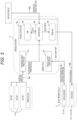
- FIG. 1 illustrates an overall configuration example of a drainage treatment system according to an embodiment of the present invention.
- a drainage treatment facility 1 includes a storage tank 2 on the upstream side and an activated carbon filtration/regeneration device 3, and is generally controlled by a drainage treatment facility control device 4 including a computer.
- the storage tank 2 drainage from a plurality of factories 5 flows in and is stored, and the activated carbon filtration/regeneration device 3 which is a water treatment device purifies drainage using activated carbon which is a solid detergent and discharges the drainage as purified water.
- the activated carbon filtration facility is subjected to the regeneration treatment due to performance deterioration, and the adsorbed substance (contaminant) generated by the regeneration is appropriately collected. As shown in FIG.
- the activated carbon filtration/regeneration device 3 includes an activated carbon adsorption device 31 (solid detergent filtering device) that performs a purification operation in which the drainage from the storage tank 2 is transformed into purified water, and a regeneration device 32 that performs a regeneration operation in which impurities adsorbed by the activated carbon adsorption device 31 are desorbed.
- an activated carbon adsorption device 31 solid detergent filtering device
- a regeneration device 32 that performs a regeneration operation in which impurities adsorbed by the activated carbon adsorption device 31 are desorbed.
- the drainage treatment facility control device 4 controls a regeneration timing, a purification timing, an activated carbon replacement timing, a liquid regenerant replacement/replenishment timing, an adsorbed substance collection timing, and the like for the activated carbon filtration/regeneration device 3.
- the drainage treatment facility control device 4 of the present invention receives, in addition to operating plan information Sg1 of the plurality of factories 5, weather information (rain information) Sg2, drainage concentration information Sg3 from a concentration sensor 6, contamination information S4 from a DME contamination degree sensor 7 provided in the regeneration device 32 in the activated carbon filtration/regeneration device 3, and purified water concentration information Sg5 from a concentration sensor 8, and determines each timing and the like.
- the activated carbon filtration/regeneration device 3 is configured as shown in FIG. 2 , for example.
- the activated carbon filtration/regeneration device 3 of FIG. 2 mainly includes a treatment tank 22, a pump 21, a condenser 29, an evaporator 28, and a plurality of valves V (V11 to V15), performs an activated carbon filtration treatment through a path from the storage tank 2 to the treatment tank 22 (activated carbon adsorption device 31), and performs a regeneration treatment on the treatment tank 22 by regeneration device 32 configured by a path from the treatment tank 22 to the treatment tank 22 again via the evaporator 28, the condenser 29, and the pump 21.
- the valves V11, V12, and V15 are closed, and the valves V13 and V14 are operated in an opened state.
- impurities are adsorbed to the adsorbent, and purified water containing no impurities is obtained from the outlet of the treatment tank.
- the operation is temporarily stopped before the impurities leak, and the mode shifts to the adsorbent regeneration mode. Water is removed from the treatment tank at the time of a transition, and water and impurities remain attached to the adsorbent.
- the valves V11 and V12 are opened, and the valves V13 and V14 are operated in a closed state.
- the liquid regenerant that regenerates the adsorbent for example, liquefied dimethyl ether (DME) is used as a substance A that is a gas at normal temperature and normal pressure.
- DME liquefied dimethyl ether
- the substance A is held at a saturated vapor pressure in the circulation path in the regeneration mode, and part of the substance A exists in a liquefied state.
- changes in temperature and pressure are described in the figure. They have different values depending on the substance A to be used, but is an example described to describe the flow of energy.
- the liquefied substance A is extracted from the lower portion of the condenser 29 and fed to the treatment tank 22 through the valve V11 by the pump 21.
- the adsorbent is immersed in the fed liquefied substance A.
- the impurities adsorbed on the adsorbent are desorbed due to high affinity with the liquefied substance A, and are dissolved in the liquefied substance A together with water.
- the liquefied substance A in which water and impurities are dissolved is fed to the evaporator 28 through the valve 12.
- the evaporator 28 energy corresponding to latent heat for vaporizing the liquefied substance A is supplied, only the liquefied substance A having the lowest boiling point is vaporized, and impurities and water remain.
- the vaporized substance A is fed to the condenser 29 and cooled, whereby the substance A is liquefied.
- the liquefied substance A obtained here is fed again to the treatment tank 22 and used again for desorption of impurities from the adsorbent.
- valve V12 is closed, the liquefied substance A is extracted from the treatment tank 22 by the reverse rotation of the pump 1 or a separately prepared extraction pump, and then the valve 15 is opened to decompress or open the treatment tank 22 to the atmosphere, whereby the liquefied substance A attached to the adsorbent is vaporized, so that a regenerated adsorbent having restored adsorption capability and being close to a new one can be obtained.
- the pump 1 is used for circulating the substance A, but its function can be substituted by a compressor. Since the compressor is a device that circulates gas, the compressor may be installed downstream of the evaporator 28 and upstream of the condenser 29 when used in the present embodiment.
- FIG. 3 illustrates a specific configuration example of the drainage treatment facility control device 4.
- the drainage treatment facility control device 4 is generally configured by a computer, and is expressed here for convenience by a processing function executed by the computer.
- the processing function of the drainage treatment facility control device 4 is configured by a discharged amount prediction unit 41, a physical quantity detection unit 42, and a process control unit 43, and the illustrated embodiment illustrates an example in which a training function is used with the configuration of the process control unit 43.
- the process control unit 43 includes a training device 45, a database 44, and a command unit 46. Note that the process control unit 43 may be realized by a general control theory.
- the discharged amount prediction unit 41 in the drainage treatment facility control device 4 acquires the operating plan information Sg1 of each of the plurality of factories 5 discharging drainage into the storage tank 2, predicts the amount of discharged drainage from a factory from the operating plan information Sg1, and predicts the total amount of discharged drainage from all the factories.
- the operating plan information Sg1 in this case may be short-term information such as that of the next day, or medium- or long-term information on a weekly or monthly basis, but it is desirable that a time equal to or longer than the regeneration treatment time T for the activated carbon filtration/regeneration device 3 described later can be secured. This means that the operating plan information Sg1 including an operating plan in the future for the time T or more for which the purification treatment of the drainage is switched to the regeneration treatment of the filtration device, and the purification treatment of the drainage is resumed is required.
- the physical quantity detection unit 42 detects a concentration, a water level, a flow rate, a temperature, and the like from various sensors. Although only the concentration and contamination degree sensors 6, 7, and 8 are illustrated in FIG. 1 , a water level sensor that detects the water level in the storage tank 2, a flow rate sensor that detects the flow rate flowing into or out of the storage tank 2, a temperature sensor that detects the temperature in the activated carbon filtration/regeneration device 3, and the like are provided in addition to these sensors, and are appropriately transmitted to the physical quantity detection unit 42 and used for a subsequent treatment.
- FIG. 4 is a flowchart illustrating processing contents of the process control unit 43, and it may be useful to use a training function for part of this processing.
- the discharged amount prediction value at the future time point predicted by the discharged amount prediction unit 41 various physical quantities at the current time point detected by the physical quantity detection unit 42, the precipitation amount prediction value, and the allowable value (limit value) for each of the physical quantities are imported.
- each physical quantity at the prediction time point of the discharged amount prediction value is estimated and predicted. Note that this processing may be calculated using a causal relationship between physical quantities, or a training function may be used.
- the processing steps S3, S4, and S5 it is confirmed that the contamination concentration of the purified water, the water level prediction value of the storage tank 2, and the contamination degree of a treatment layer 22 to be particularly monitored exceed the respective allowable values as the physical quantities.
- the process returns to the processing step S2, and the above processing is continuously executed.
- the process moves to the processing steps S6, S7, and S8, and an appropriate countermeasure according to each state is taken.
- the contamination concentration of the purified water and the contamination degree of the treatment layer 22 are values at a current time point or a future time point
- the water level of the storage tank 2 is a prediction value at a future time point. That is, it is preferable that regarding the exceeding the allowable values of the contamination concentration of the purified water and the contamination degree of the treatment layer 22, the monitoring result at the current time point (or the prediction result at the future time point) is reflected in the control at the current time point (or the future time point), and regarding the water level of the storage tank 2, prediction control based on the prediction result at the future time point (the control execution time point is the future time point) is performed.
- concentration management of the inflow water As described in the fourth embodiment about this, it is preferable to apply the prediction control as in the water level of the storage tank 2.
- the countermeasures in the processing steps S6, S7, and S8 may be individually set in advance, in particular, since the exceeding event of the water level of the storage tank 2 is a predicted event at a future time point, it is possible to take many suboptimal measures between the current time point and the predicted event occurrence time point. Specifically, in a case where the training function is used, it is possible to propose an appropriate countermeasure in consideration of the past cases and the like in a comprehensive manner in the processing step S7.
- the drainage treatment facility control device 4 As a usage scene of the drainage treatment facility control device 4 according to the present invention, it is conceivable to make the drainage treatment facility control device 4 semi-automatic or fully automatic.
- the semi-automatic it is configured as an assistance device, and the countermeasures in the processing steps S6, S7, and S8, the training result in the processing step S7, and the like are visually presented to the administrator together with other information to seek the determination.
- the semi-automatic it is also useful to present the future prediction result of the contamination concentration of the purified water and the contamination degree of the treatment layer 22 to the administrator and to inform the administrator that a response is required in the near future.
- the determination result is transmitted to the valve V which is an operation end of the activated carbon filtration/regeneration device 3 and the pump (not illustrated) installed in a drainage supply line in the processing step S9, and they are controlled.
- an example of the countermeasure in the processing step S6 is a normal operation of shifting to the regeneration operation and resuming the purification operation after completion of the regeneration operation.
- An example of the countermeasure in the processing step S8 is a normal operation of replacing and replenishing the DME and replacing activated carbon.
- the countermeasure in the processing step S7 is specific to the present invention, and details thereof will be described later.
- FIG. 5a shows an example of a conventional drainage treatment facility operation without using the present invention.
- a time-series change example of the water level, the purified water flow rate, the inflow amount, and the purified water contamination concentration of the storage tank 2 is illustrated, and the operation is stopped after the purification operation and the regeneration operation, and the purification operation, the regeneration operation, and the operation stop are repeatedly executed again as a typical pattern.
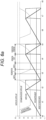
- FIG. 5a is an example of a conventional drainage treatment facility operation, and is a result based on monitoring at the current time and control thereof. Therefore, this overflow cannot be prevented.
- the current time is, for example, the time point of t0, and a change event such as each physical quantity up to the time point t1 in FIG. 5a is predicted.
- the countermeasure in step S7 used by the drainage treatment facility control device 4 is to provide a system capable of treating drainage at the timing of an event in which the drainage from the factory 5 to the storage tank 2 increases by performing the purification operation at time t1.
- a system is provided in which a set operation of one time purification operation, one time regeneration operation, and one time operation stop is completed before time t1, and the purified water contamination concentration is low at time t1.
- a set operation of one time purification operation, one time regeneration operation, and one time operation stop is completed within a time secured by shortening the operation stop period. In a state where the purified water contamination concentration is low, the water level of the storage tank 2 can be lowered to secure a sufficient period during which the possibility of overflow is prevented.
- the countermeasure in step S7 in FIG. 4 is to complete a set operation of one time purification operation, one time regeneration operation, and one time operation stop in advance with respect to the prediction result that the overflow of drainage occurs in the storage tank 2, and to set to be during the purification operation, preferably immediately after the start of the purification operation at the time when the overflow of drainage is predicted.
- FIGS. 5a and 5b show that the control is performed at the preceding stage so as to bring the operation into the regeneration operation at time t1 at which the overflow is predicted.
- a specific example of a method for realizing this specific countermeasure in relation to the activated carbon contamination degree will be described with reference to FIGS. 6a , 6b , and 6c .
- FIG. 6a illustrates an operation example of a drainage treatment facility during a normal operation.
- the time-series changes in the water level, the purified water flow rate, the inflow amount, and the activated carbon contamination degree of the storage tank 2 are expressed together with the water level upper limit and the activated carbon contamination degree upper limit, and a typical pattern is operated in which the operation is stopped after the purification operation and the regeneration operation, and the purification operation, the regeneration operation, and the operation stop are repeatedly executed again.
- the switching periods before and after the regeneration operation are also displayed.
- the simulation condition assumed here is that the inflow amount is constant, the amount of purified water is 3.6 times, the water level is a difference between inflow and outflow, the mode switching time before and after regeneration is 0.45 hours, the 100% regeneration time is 0.95 hours, and the 50% regeneration time is 0.3 hours, and the water level of 2/3 of the full water is set as the reference for starting the purification operation is that.
- FIG. 6b shows that an overflow current occurred at t6 which is a future time point as a prediction result. Note that time t6 is within the switching time period after the regeneration treatment, but is within the range of the regeneration operation including the switching time period. In any case, since it is not time of the purification operation, water treatment cannot be performed, that is, it is a period in which the water level control of the storage tank 2 is not functioning.
- FIG. 6c illustrates an effective countermeasure that can be taken between the current time t0 and the overflow time t6 in a state where the occurrence of the overflow is predicted.
- the countermeasure 1 is to extend the regeneration operation period from time t3 to time t4 so as to achieve 100% regeneration with respect to the degree of activated carbon contamination in anticipation of an increase in load.
- the countermeasure 2 is to switch the operation stop period after the regeneration to the short time execution a at time t5 after the purification operation, which is temporarily stopped due to a decrease in the water level.
- the countermeasure 3 is to the purification operation is resumed after the operation is stopped, and performs the purification operation up to the limit.
- the regeneration operation is executed at the overflow occurrence prediction time, but in the regeneration at this time, an increase in the tank water level is predicted to determine the target removal performance (regeneration time) (in this case, 50%), and the overflow occurs regardless of whether the regeneration is too short or too long.
- the target removal performance in this case, 50%
- FIG. 6c The idea of FIG. 6c is the same as that of FIG. 5b , and in short, when an overflow due to an increase in load is predicted, the removal performance is recovered to 100% in advance.
- a specific control method is realized by reflecting a prediction result in actual operation using a function of a training device, and this can be said to be a countermeasure at the time of occurrence of abnormality such as overflow.
- reducing the running cost by using the function of the training device will be described with reference to FIGS. 7a and 7b .
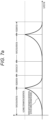
- FIG. 7a shows an example of a normal purification operation, and as in FIG. 5a , the operation is stopped after purification and regeneration, and purification, regeneration, and operation stop are repeatedly executed again.
- the regeneration time may be shortened using the prediction result as illustrated in FIG. 7b .
- the operation is continued while the state in which the contamination degree is high is maintained, and the contamination degree is not lowered.
- the adsorption and desorption characteristics of the activated carbon can be utilized to lower the regeneration degree, and the regeneration cost can be reduced.
- the purified water concentration immediately after regeneration is compared with its upper limit value.
- the upper limit value here is not an allowable value as a determination criterion for switching the purification operation to the regeneration operation, but is a criterion for determining that it is time to replace the activated carbon in terms of the purification performance due to deterioration of the activated carbon, and the activated carbon adsorption device 31 is stopped in the processing step 13 due to exceeding of the upper limit value to replace the activated carbon.
- the activated carbon adsorption device 31 (treatment tank 22) in the processing step S11 starts to operate. In this case, it is needless to say that the activated carbon adsorption operation is started after it is confirmed that the predetermined performance is achieved.
- the processing step S14 it is checked whether there is a special instruction from the drainage treatment facility control device 4, and when there is the instruction, the process proceeds to the processing step S22, and when there is no instruction, the process is viewed in the normal treatment of the processing step S15.
- the special instruction from the drainage treatment facility control device 4 is, for example, an instruction about the operation mode illustrated in FIG. 6b , and the regeneration operation is performed in the designated execution period, thereby performing the cost-oriented operation.
- the purified water concentration is compared with an allowable value by the normal treatment in the processing step S15, and when the concentration exceeds the allowable value, the regeneration operation is started in the processing step S18.
- processing step S16 of performing prediction monitoring of the water level of the storage tank 2 is subsequently executed.
- the process returns to the processing step S11, and the normal purification treatment (activated carbon adsorption treatment) is continued.
- the water level of the storage tank 2 is equal to or greater than the allowable value in the processing step S16, the preliminary preventive measure against overflow at the prediction time point shown in FIG. 5b is executed in the processing step S17.
- the regeneration operation in the processing step S18 is executed unless there is a stop instruction from the drainage treatment facility control device 4 by the determination in the processing step S19, and the regeneration device is stopped and the DME is replaced in the processing step S20 when there is no stop instruction, and in the processing step S21 when the measurement value of the DME sensor is equal to or greater than the allowable value.
- the concentration inflow concentration in the storage tank 2 changes, the concentration is relaxed in the storage tank 2 and fed to the activated carbon filtration/regeneration device 3, but even in the case of management of the concentration, the effect of the preliminary countermeasure by the operation change by the concentration change prediction can be expected.
- the amount of water that can be purified decreases, so that the possibility of overflow increases.
- the amount of purified water can be increased by improving the removal performance of activated carbon in advance. Therefore, the method of changing the method of operating the purification facility for predicting the flow rate variation described above can also be applied to the concentration variation.
- the purification using the activated carbon as the solid detergent and the regeneration using the liquefied gas as the liquid regenerant have been described as an example, but the present invention is not limited to this combination, and other adsorbents and sand filtration can also be used as the solid detergent instead of the activated carbon.
- sand filtration can physically remove solid materials, and silica gel or alumina gel exhibits an adsorption action in addition to sand filtration, so that dissolved substances can also be removed.
- activated carbon is different from the above in that the types of substances that can be adsorbed and the adsorption amount can be increased.
- the regenerating agent to be combined is not limited to the liquefied gas, and an appropriate regenerating agent may be selected from the combination of the object to be removed and the purifying agent.
Landscapes
- Chemical & Material Sciences (AREA)
- Life Sciences & Earth Sciences (AREA)
- Hydrology & Water Resources (AREA)
- Engineering & Computer Science (AREA)
- Environmental & Geological Engineering (AREA)
- Water Supply & Treatment (AREA)
- Organic Chemistry (AREA)
- Inorganic Chemistry (AREA)
- Water Treatment By Sorption (AREA)
Abstract
Description
- The present invention relates to a drainage treatment system and a method for treating drainage from a plurality of factories.
- Various facilities for treating drainage are known, and for example, according to
PTL 1, it is possible to realize a more compact drainage treatment facility than the conventional one by purification with an adsorbent and regeneration with a liquefied gas. - PTL 1:
WO 2015/033455 A - The treatment facility of
PTL 1 has an advantage that the purification treatment of drainage and the regeneration treatment of the adsorbent can be performed compactly and easily, and is promising as a future drainage facility, but a separate storage tank is required at a preceding stage. - Drainage from a factory is stored in the storage tank, it is difficult to predict the fluctuation of the amount of water discharged from the plurality of factories particularly when drainage from a large number of factories is received, so that a huge storage tank is required before the drainage treatment device for the purpose of leveling the inflow amount. In addition, since inundation (overflow) from the storage tank is not allowed, it is necessary to stop the operation of the factory when the water level is high.
- In consideration of the above, an object of the present invention is to provide a drainage treatment system and a method suitable for preventing inundation (overflow) while enabling downsizing of a storage tank when receiving drainage from a large number of factories.
- As described above, according to the present invention, there is provided a drainage treatment system configured to store drainage from a plurality of factories in a storage tank, purify the drainage from the storage tank by a water treatment device including a combination of a solid detergent and a liquid regenerant, and control the water treatment device by a drainage treatment facility control device, wherein the water treatment device includes a drainage treatment facility control device that performs a purification operation in which the drainage from the storage tank is transformed into purified water and a regeneration device that performs a regeneration operation in which impurities adsorbed by the solid detergent filtering device are desorbed, and the drainage treatment facility control device acquires operating plan information from each of the plurality of factories to predict an amount of discharged drainage from each factory, predicts a transition of a physical quantity at each of various locations of the storage tank and the water treatment device at a time of the predicted discharged amount, and controls timing of an operation by the water treatment device in accordance with a result of the prediction. In addition, according to the present invention, there is provided a drainage treatment method for storing drainage from a plurality of factories in a storage tank and purifying the drainage from the storage tank by a water treatment device, wherein the water treatment device performs a purification operation in which the drainage from the storage tank is transformed into purified water and a regeneration operation in which impurities adsorbed to a solid detergent are desorbed, and the method includes acquiring an operating plan information from each of the plurality of factories to predict an amount of discharged drainage from each factory, predicting a transition of a physical quantity at each of various locations of the storage tank and the water treatment device at a time of the predicted discharged amount, and determining timing of an operation by the water treatment device in accordance with a result of the prediction.
- According to the present invention, it is possible to provide a drainage treatment system and a method suitable for preventing inundation (overflow) while enabling downsizing of a storage tank when receiving drainage from a large number of factories.
-
- [
FIG. 1] FIG. 1 is a view showing an overall configuration example of a drainage treatment system according to an embodiment of the present invention. - [
FIG. 2] FIG. 2 is a view showing an overall configuration example of an activated carbon filtration/regeneration device to which the present invention is applied. - [
FIG. 3] FIG. 3 is a diagram showing a specific configuration example of a drainage treatmentfacility control device 4. - [
FIG. 4] FIG. 4 is a flowchart showing processing contents in aprocess control unit 43. - [
FIG. 5a] FIG. 5a is a view showing an operation example of a conventional drainage treatment facility. - [
FIG. 5b] FIG. 5b is a view showing an operation example of a drainage treatment facility performing a future prediction according to the present invention. - [
FIG. 6a] FIG. 6a is a view showing an operation example of a drainage treatment facility during a normal operation. - [
FIG. 6b] FIG. 6b is a diagram illustrating that an overflow current has occurred at t6 which is a future time point as a prediction result. - [
FIG. 6c] FIG. 6c is a diagram illustrating an effective countermeasure in a state where occurrence of overflow is predicted. - [
FIG. 7a] FIG. 7a is a diagram showing an example of a normal purification operation. - [
FIG. 7b] FIG. 7b is a diagram illustrating an operation example of a cost-oriented drainage treatment facility performing a future prediction according to the present invention. - [
FIG. 8] FIG. 8 is a view showing an operation procedure of the drainage treatment system according to the present invention. - Hereinafter, embodiments of the present invention will be described with reference to the drawings.
-
FIG. 1 illustrates an overall configuration example of a drainage treatment system according to an embodiment of the present invention. Adrainage treatment facility 1 includes astorage tank 2 on the upstream side and an activated carbon filtration/regeneration device 3, and is generally controlled by a drainage treatmentfacility control device 4 including a computer. In thestorage tank 2, drainage from a plurality offactories 5 flows in and is stored, and the activated carbon filtration/regeneration device 3 which is a water treatment device purifies drainage using activated carbon which is a solid detergent and discharges the drainage as purified water. Further, the activated carbon filtration facility is subjected to the regeneration treatment due to performance deterioration, and the adsorbed substance (contaminant) generated by the regeneration is appropriately collected. As shown inFIG. 2 and described later in detail, the activated carbon filtration/regeneration device 3 includes an activated carbon adsorption device 31 (solid detergent filtering device) that performs a purification operation in which the drainage from thestorage tank 2 is transformed into purified water, and aregeneration device 32 that performs a regeneration operation in which impurities adsorbed by the activatedcarbon adsorption device 31 are desorbed. - The drainage treatment
facility control device 4 controls a regeneration timing, a purification timing, an activated carbon replacement timing, a liquid regenerant replacement/replenishment timing, an adsorbed substance collection timing, and the like for the activated carbon filtration/regeneration device 3. For these treatments, the drainage treatmentfacility control device 4 of the present invention receives, in addition to operating plan information Sg1 of the plurality offactories 5, weather information (rain information) Sg2, drainage concentration information Sg3 from aconcentration sensor 6, contamination information S4 from a DMEcontamination degree sensor 7 provided in theregeneration device 32 in the activated carbon filtration/regeneration device 3, and purified water concentration information Sg5 from a concentration sensor 8, and determines each timing and the like. - The activated carbon filtration/
regeneration device 3 is configured as shown inFIG. 2 , for example. The activated carbon filtration/regeneration device 3 ofFIG. 2 mainly includes atreatment tank 22, apump 21, acondenser 29, anevaporator 28, and a plurality of valves V (V11 to V15), performs an activated carbon filtration treatment through a path from thestorage tank 2 to the treatment tank 22 (activated carbon adsorption device 31), and performs a regeneration treatment on thetreatment tank 22 byregeneration device 32 configured by a path from thetreatment tank 22 to thetreatment tank 22 again via theevaporator 28, thecondenser 29, and thepump 21. - With the above configuration, first, in the normal drainage treatment mode (purification mode), the valves V11, V12, and V15 are closed, and the valves V13 and V14 are operated in an opened state. By bringing drainage from the
storage tank 2 into contact with the adsorbent with which thetreatment tank 22 is filled, impurities are adsorbed to the adsorbent, and purified water containing no impurities is obtained from the outlet of the treatment tank. When the operation is continued in this state, the adsorption saturation is reached, and the impurities leak. Therefore, the operation is temporarily stopped before the impurities leak, and the mode shifts to the adsorbent regeneration mode. Water is removed from the treatment tank at the time of a transition, and water and impurities remain attached to the adsorbent. - In the adsorbent regeneration mode, the valves V11 and V12 are opened, and the valves V13 and V14 are operated in a closed state. As the liquid regenerant that regenerates the adsorbent, for example, liquefied dimethyl ether (DME) is used as a substance A that is a gas at normal temperature and normal pressure. The substance A is held at a saturated vapor pressure in the circulation path in the regeneration mode, and part of the substance A exists in a liquefied state. In addition, changes in temperature and pressure are described in the figure. They have different values depending on the substance A to be used, but is an example described to describe the flow of energy.
- First, the liquefied substance A is extracted from the lower portion of the
condenser 29 and fed to thetreatment tank 22 through the valve V11 by thepump 21. In thetreatment tank 22, the adsorbent is immersed in the fed liquefied substance A. At this time, the impurities adsorbed on the adsorbent are desorbed due to high affinity with the liquefied substance A, and are dissolved in the liquefied substance A together with water. Next, the liquefied substance A in which water and impurities are dissolved is fed to theevaporator 28 through the valve 12. In theevaporator 28, energy corresponding to latent heat for vaporizing the liquefied substance A is supplied, only the liquefied substance A having the lowest boiling point is vaporized, and impurities and water remain. The vaporized substance A is fed to thecondenser 29 and cooled, whereby the substance A is liquefied. The liquefied substance A obtained here is fed again to thetreatment tank 22 and used again for desorption of impurities from the adsorbent. - By repeating the cycle of the change in state of the substance A a plurality of times as necessary, most of the impurities attached to the adsorbent are desorbed. When the desorption is completed, the valve V12 is closed, the liquefied substance A is extracted from the
treatment tank 22 by the reverse rotation of thepump 1 or a separately prepared extraction pump, and then thevalve 15 is opened to decompress or open thetreatment tank 22 to the atmosphere, whereby the liquefied substance A attached to the adsorbent is vaporized, so that a regenerated adsorbent having restored adsorption capability and being close to a new one can be obtained. - In the present embodiment, the
pump 1 is used for circulating the substance A, but its function can be substituted by a compressor. Since the compressor is a device that circulates gas, the compressor may be installed downstream of theevaporator 28 and upstream of thecondenser 29 when used in the present embodiment. -
FIG. 3 illustrates a specific configuration example of the drainage treatmentfacility control device 4. The drainage treatmentfacility control device 4 is generally configured by a computer, and is expressed here for convenience by a processing function executed by the computer. The processing function of the drainage treatmentfacility control device 4 is configured by a dischargedamount prediction unit 41, a physicalquantity detection unit 42, and aprocess control unit 43, and the illustrated embodiment illustrates an example in which a training function is used with the configuration of theprocess control unit 43. In this case, theprocess control unit 43 includes atraining device 45, adatabase 44, and acommand unit 46. Note that theprocess control unit 43 may be realized by a general control theory. - The discharged
amount prediction unit 41 in the drainage treatmentfacility control device 4 acquires the operating plan information Sg1 of each of the plurality offactories 5 discharging drainage into thestorage tank 2, predicts the amount of discharged drainage from a factory from the operating plan information Sg1, and predicts the total amount of discharged drainage from all the factories. In general, while there is some correlation between the operating plan information Sg1 and the amount of discharged drainage from the factory, there may be a variation factor due to characteristics of devices to be used, and its usage (for example, in a case where a storage tank is provided in a factory and drainage is discharged in a batch processing manner, and the like), seasonal factors, and the like, so that in terms of grasping these relationships, a device configuration in which a more accurate discharged amount can be predicted by applying a so-called training function is preferable. However, in the present invention, it is sufficient that prediction can be performed, and a specific implementation method of prediction is not limited. - The operating plan information Sg1 in this case may be short-term information such as that of the next day, or medium- or long-term information on a weekly or monthly basis, but it is desirable that a time equal to or longer than the regeneration treatment time T for the activated carbon filtration/
regeneration device 3 described later can be secured. This means that the operating plan information Sg1 including an operating plan in the future for the time T or more for which the purification treatment of the drainage is switched to the regeneration treatment of the filtration device, and the purification treatment of the drainage is resumed is required. - The physical
quantity detection unit 42 detects a concentration, a water level, a flow rate, a temperature, and the like from various sensors. Although only the concentration andcontamination degree sensors FIG. 1 , a water level sensor that detects the water level in thestorage tank 2, a flow rate sensor that detects the flow rate flowing into or out of thestorage tank 2, a temperature sensor that detects the temperature in the activated carbon filtration/regeneration device 3, and the like are provided in addition to these sensors, and are appropriately transmitted to the physicalquantity detection unit 42 and used for a subsequent treatment. - Although the
process control unit 43 exemplifies the configuration when using the training function, the present invention is not limited to the use of the training function. In short, in theprocess control unit 43 is required to realize the following processing illustrated inFIG. 4. FIG. 4 is a flowchart illustrating processing contents of theprocess control unit 43, and it may be useful to use a training function for part of this processing. - In the first processing step S1 of the flow of
FIG. 4 , the discharged amount prediction value at the future time point predicted by the dischargedamount prediction unit 41, various physical quantities at the current time point detected by the physicalquantity detection unit 42, the precipitation amount prediction value, and the allowable value (limit value) for each of the physical quantities are imported. In the processing step S2, each physical quantity at the prediction time point of the discharged amount prediction value is estimated and predicted. Note that this processing may be calculated using a causal relationship between physical quantities, or a training function may be used. - In the processing steps S3, S4, and S5, it is confirmed that the contamination concentration of the purified water, the water level prediction value of the
storage tank 2, and the contamination degree of atreatment layer 22 to be particularly monitored exceed the respective allowable values as the physical quantities. When it is determined that the allowable value is not exceeded (No), the process returns to the processing step S2, and the above processing is continuously executed. When it is determined that the allowable value is exceeded (Yes), the process moves to the processing steps S6, S7, and S8, and an appropriate countermeasure according to each state is taken. - Here, it is preferable that the contamination concentration of the purified water and the contamination degree of the
treatment layer 22 are values at a current time point or a future time point, and the water level of thestorage tank 2 is a prediction value at a future time point. That is, it is preferable that regarding the exceeding the allowable values of the contamination concentration of the purified water and the contamination degree of thetreatment layer 22, the monitoring result at the current time point (or the prediction result at the future time point) is reflected in the control at the current time point (or the future time point), and regarding the water level of thestorage tank 2, prediction control based on the prediction result at the future time point (the control execution time point is the future time point) is performed. As a physical quantity other than the above, there is concentration management of the inflow water. As described in the fourth embodiment about this, it is preferable to apply the prediction control as in the water level of thestorage tank 2. - Although the countermeasures in the processing steps S6, S7, and S8 may be individually set in advance, in particular, since the exceeding event of the water level of the
storage tank 2 is a predicted event at a future time point, it is possible to take many suboptimal measures between the current time point and the predicted event occurrence time point. Specifically, in a case where the training function is used, it is possible to propose an appropriate countermeasure in consideration of the past cases and the like in a comprehensive manner in the processing step S7. - As a usage scene of the drainage treatment
facility control device 4 according to the present invention, it is conceivable to make the drainage treatmentfacility control device 4 semi-automatic or fully automatic. In the case of the semi-automatic, it is configured as an assistance device, and the countermeasures in the processing steps S6, S7, and S8, the training result in the processing step S7, and the like are visually presented to the administrator together with other information to seek the determination. Note that, in the case of the semi-automatic, it is also useful to present the future prediction result of the contamination concentration of the purified water and the contamination degree of thetreatment layer 22 to the administrator and to inform the administrator that a response is required in the near future. When it is fully automated, the determination result is transmitted to the valve V which is an operation end of the activated carbon filtration/regeneration device 3 and the pump (not illustrated) installed in a drainage supply line in the processing step S9, and they are controlled. - Note that an example of the countermeasure in the processing step S6 is a normal operation of shifting to the regeneration operation and resuming the purification operation after completion of the regeneration operation. An example of the countermeasure in the processing step S8 is a normal operation of replacing and replenishing the DME and replacing activated carbon. On the other hand, the countermeasure in the processing step S7 is specific to the present invention, and details thereof will be described later.
-
FIG. 5a shows an example of a conventional drainage treatment facility operation without using the present invention. In this example, a time-series change example of the water level, the purified water flow rate, the inflow amount, and the purified water contamination concentration of thestorage tank 2 is illustrated, and the operation is stopped after the purification operation and the regeneration operation, and the purification operation, the regeneration operation, and the operation stop are repeatedly executed again as a typical pattern. - In this illustrative example, an example in which the purified water contamination concentration and the water level of the
storage tank 2 shown in the processing steps S3 and S4 are to be compared with the allowable values and monitored is taken. According to this, the purification operation is switched to the regeneration operation at the timing when the purified water contamination concentration exceeds the allowable value, and after completion of the regeneration, the operation is returned to the purification operation after securing the operation stop period. - On the other hand, it is assumed that during the activated carbon regeneration treatment at time t1 when the supply of drainage from the
storage tank 2 to the activated carbon filtration/regeneration device 3 is stopped, drainage from thefactory 5 to thestorage tank 2 increases, and overflow of drainage occurs in thestorage tank 2.FIG. 5a is an example of a conventional drainage treatment facility operation, and is a result based on monitoring at the current time and control thereof. Therefore, this overflow cannot be prevented. - On the other hand, in a case where the future prediction using the operating plan information Sg1 of the plurality of
factories 5 is performed according to the present invention, it is possible to cope with as illustrated inFIG. 5b . As a premise ofFIG. 5b , the current time is, for example, the time point of t0, and a change event such as each physical quantity up to the time point t1 inFIG. 5a is predicted. - In this case, the countermeasure in step S7 used by the drainage treatment
facility control device 4 according to the present invention is to provide a system capable of treating drainage at the timing of an event in which the drainage from thefactory 5 to thestorage tank 2 increases by performing the purification operation at time t1. In addition, as a premise, since the purified water contamination concentration is a switching condition from the purification operation to the regeneration operation, a system is provided in which a set operation of one time purification operation, one time regeneration operation, and one time operation stop is completed before time t1, and the purified water contamination concentration is low at time t1. In a specific operation, a set operation of one time purification operation, one time regeneration operation, and one time operation stop is completed within a time secured by shortening the operation stop period. In a state where the purified water contamination concentration is low, the water level of thestorage tank 2 can be lowered to secure a sufficient period during which the possibility of overflow is prevented. - As is clear from the above, the countermeasure in step S7 in
FIG. 4 is to complete a set operation of one time purification operation, one time regeneration operation, and one time operation stop in advance with respect to the prediction result that the overflow of drainage occurs in thestorage tank 2, and to set to be during the purification operation, preferably immediately after the start of the purification operation at the time when the overflow of drainage is predicted. -
FIGS. 5a and5b show that the control is performed at the preceding stage so as to bring the operation into the regeneration operation at time t1 at which the overflow is predicted. A specific example of a method for realizing this specific countermeasure in relation to the activated carbon contamination degree will be described with reference toFIGS. 6a ,6b , and6c . -
FIG. 6a illustrates an operation example of a drainage treatment facility during a normal operation. In this example, the time-series changes in the water level, the purified water flow rate, the inflow amount, and the activated carbon contamination degree of thestorage tank 2 are expressed together with the water level upper limit and the activated carbon contamination degree upper limit, and a typical pattern is operated in which the operation is stopped after the purification operation and the regeneration operation, and the purification operation, the regeneration operation, and the operation stop are repeatedly executed again. In this drawing, the switching periods before and after the regeneration operation are also displayed. - The simulation condition assumed here is that the inflow amount is constant, the amount of purified water is 3.6 times, the water level is a difference between inflow and outflow, the mode switching time before and after regeneration is 0.45 hours, the 100% regeneration time is 0.95 hours, and the 50% regeneration time is 0.3 hours, and the water level of 2/3 of the full water is set as the reference for starting the purification operation is that.
-
FIG. 6b shows that an overflow current occurred at t6 which is a future time point as a prediction result. Note that time t6 is within the switching time period after the regeneration treatment, but is within the range of the regeneration operation including the switching time period. In any case, since it is not time of the purification operation, water treatment cannot be performed, that is, it is a period in which the water level control of thestorage tank 2 is not functioning. -
FIG. 6c illustrates an effective countermeasure that can be taken between the current time t0 and the overflow time t6 in a state where the occurrence of the overflow is predicted. Thecountermeasure 1 is to extend the regeneration operation period from time t3 to time t4 so as to achieve 100% regeneration with respect to the degree of activated carbon contamination in anticipation of an increase in load. Thecountermeasure 2 is to switch the operation stop period after the regeneration to the short time execution a at time t5 after the purification operation, which is temporarily stopped due to a decrease in the water level. Thecountermeasure 3 is to the purification operation is resumed after the operation is stopped, and performs the purification operation up to the limit. - As a result, the regeneration operation is executed at the overflow occurrence prediction time, but in the regeneration at this time, an increase in the tank water level is predicted to determine the target removal performance (regeneration time) (in this case, 50%), and the overflow occurs regardless of whether the regeneration is too short or too long.
- The idea of
FIG. 6c is the same as that ofFIG. 5b , and in short, when an overflow due to an increase in load is predicted, the removal performance is recovered to 100% in advance. - In the first embodiment, a specific control method is realized by reflecting a prediction result in actual operation using a function of a training device, and this can be said to be a countermeasure at the time of occurrence of abnormality such as overflow. On the other hand, in the second embodiment, reducing the running cost by using the function of the training device will be described with reference to
FIGS. 7a and7b . -
FIG. 7a shows an example of a normal purification operation, and as inFIG. 5a , the operation is stopped after purification and regeneration, and purification, regeneration, and operation stop are repeatedly executed again. On the other hand, when it is known in advance that the amount of discharged drainage from the factories is small and the low load state continues as the discharged amount prediction result from the operating plan information Sg1 of the plurality offactories 5, the regeneration time may be shortened using the prediction result as illustrated inFIG. 7b . As a result, the operation is continued while the state in which the contamination degree is high is maintained, and the contamination degree is not lowered. As a result, according to this operation mode, the adsorption and desorption characteristics of the activated carbon can be utilized to lower the regeneration degree, and the regeneration cost can be reduced. - In the third embodiment, a general overall operation procedure of the drainage treatment system according to the present invention will be described with reference to
FIG. 8 . In the first processing step S11 in this flow, drainage is purified by the operation of the activated carbon adsorption device 31 (treatment tank 22), and the regeneration operation is appropriately performed. - In the processing step S12, the purified water concentration immediately after regeneration is compared with its upper limit value. Note that the upper limit value here is not an allowable value as a determination criterion for switching the purification operation to the regeneration operation, but is a criterion for determining that it is time to replace the activated carbon in terms of the purification performance due to deterioration of the activated carbon, and the activated
carbon adsorption device 31 is stopped in the processing step 13 due to exceeding of the upper limit value to replace the activated carbon. After the replacement of the activated carbon, the activated carbon adsorption device 31 (treatment tank 22) in the processing step S11 starts to operate. In this case, it is needless to say that the activated carbon adsorption operation is started after it is confirmed that the predetermined performance is achieved. - In the processing step S14, it is checked whether there is a special instruction from the drainage treatment
facility control device 4, and when there is the instruction, the process proceeds to the processing step S22, and when there is no instruction, the process is viewed in the normal treatment of the processing step S15. Here, the special instruction from the drainage treatmentfacility control device 4 is, for example, an instruction about the operation mode illustrated inFIG. 6b , and the regeneration operation is performed in the designated execution period, thereby performing the cost-oriented operation. When there is no special instruction, the purified water concentration is compared with an allowable value by the normal treatment in the processing step S15, and when the concentration exceeds the allowable value, the regeneration operation is started in the processing step S18. - When the purified water concentration is equal to or less than the allowable value in the processing step S15, processing step S16 of performing prediction monitoring of the water level of the
storage tank 2 is subsequently executed. Here, when there is no abnormality in the transition, the process returns to the processing step S11, and the normal purification treatment (activated carbon adsorption treatment) is continued. When the water level of thestorage tank 2 is equal to or greater than the allowable value in the processing step S16, the preliminary preventive measure against overflow at the prediction time point shown inFIG. 5b is executed in the processing step S17. - The regeneration operation in the processing step S18 is executed unless there is a stop instruction from the drainage treatment
facility control device 4 by the determination in the processing step S19, and the regeneration device is stopped and the DME is replaced in the processing step S20 when there is no stop instruction, and in the processing step S21 when the measurement value of the DME sensor is equal to or greater than the allowable value. - In the first embodiment, description is made in which the contamination concentration of the purified water, the contamination degree of the
treatment layer 22, and the water level of thestorage tank 2 are monitored and controlled. On the other hand, in the fourth embodiment, management of the concentration of drainage flowing in from thestorage tank 2 will be described. - When the inflow concentration in the
storage tank 2 changes, the concentration is relaxed in thestorage tank 2 and fed to the activated carbon filtration/regeneration device 3, but even in the case of management of the concentration, the effect of the preliminary countermeasure by the operation change by the concentration change prediction can be expected. Specifically, when the contaminant concentration increases, the amount of water that can be purified decreases, so that the possibility of overflow increases. Also at this time, when an increase in the concentration is predicted in advance, the amount of purified water can be increased by improving the removal performance of activated carbon in advance. Therefore, the method of changing the method of operating the purification facility for predicting the flow rate variation described above can also be applied to the concentration variation. - In the drainage treatment in the first to fourth embodiments, the purification using the activated carbon as the solid detergent and the regeneration using the liquefied gas as the liquid regenerant have been described as an example, but the present invention is not limited to this combination, and other adsorbents and sand filtration can also be used as the solid detergent instead of the activated carbon. For example, sand filtration can physically remove solid materials, and silica gel or alumina gel exhibits an adsorption action in addition to sand filtration, so that dissolved substances can also be removed. On the other hand, activated carbon is different from the above in that the types of substances that can be adsorbed and the adsorption amount can be increased. The regenerating agent to be combined is not limited to the liquefied gas, and an appropriate regenerating agent may be selected from the combination of the object to be removed and the purifying agent.
-
- 1
- drainage treatment facility
- 2
- storage tank
- 3
- activated carbon filtration/regeneration device
- 4
- drainage treatment facility control device
- 5
- factory
- 6, 8
- concentration sensor
- 7
- contamination degree sensor
- 8, 21
- pump
- 22
- treatment tank
- 28
- evaporator
- 29
- condenser
- 41
- discharged amount prediction unit
- 42
- physical quantity detection unit
- 43
- process control unit
- 44
- database
- 45
- training device
- 46
- command unit
- V11 to V15
- valve
Claims (13)
- A drainage treatment system configured to store drainage from a plurality of factories in a storage tank, purify the drainage from the storage tank by a water treatment device including a combination of a solid detergent and a liquid regenerant, and control the water treatment device by a drainage treatment facility control device, whereinthe water treatment device includes a solid detergent filtering device that performs a purification operation in which the drainage from the storage tank is transformed into purified water and a regeneration device that performs a regeneration operation in which impurities adsorbed by the solid detergent filtering device are desorbed, andthe drainage treatment facility control device acquires operating plan information from each of the plurality of factories to predict an amount of discharged drainage from each factory, predicts a transition of a physical quantity at each of various locations of the storage tank and the water treatment device at a time of the predicted discharged amount, and controls timing of an operation by the water treatment device in accordance with a result of the prediction.
- The drainage treatment system according to claim 1, wherein when an overflow from the storage tank is predicted as a result of the prediction of the discharged amount and the transition of the physical quantity, the water treatment device is controlled in advance so that the water treatment device performs the purification operation at a time when the overflow is predicted.
- The drainage treatment system according to claim 1, wherein when a state in which the discharged amount is small continues as a result of the prediction of the discharged amount, timing of an operation by the water treatment device is controlled so that an execution time of the regeneration operation is shortened.
- The drainage treatment system according to claim 1, wherein the water treatment device is stopped and activated carbon is replaced when a concentration of the purified water exceeds an upper limit value at an initial stage of a transition from the regeneration operation to the purification operation.
- The drainage treatment system according to claim 1, wherein the regeneration device is stopped and the liquid regenerant is replaced when a contamination concentration, of the liquid regenerant, detected by a contamination degree sensor provided in the regeneration device exceeds an upper limit value, in the regeneration operation.
- The drainage treatment system according to any one of claims 1 to 5, wherein the solid detergent is sand.
- The drainage treatment system according to any one of claims 1 to 5, wherein the solid detergent is an adsorbent.
- The drainage treatment system according to any one of claims 1 to 5, wherein the solid detergent is activated carbon.
- A drainage treatment method for storing drainage from a plurality of factories in a storage tank and purifying the drainage from the storage tank by a water treatment device, whereinthe water treatment device performs a purification operation in which the drainage from the storage tank is transformed into purified water and a regeneration operation in which impurities adsorbed to a solid detergent are desorbed, andthe method includes acquiring an operating plan information from each of the plurality of factories to predict an amount of discharged drainage from each factory, predicting a transition of a physical quantity at each of various locations of the storage tank and the water treatment device at a time of the predicted discharged amount, and determining timing of an operation by the water treatment device in accordance with a result of the prediction.
- The drainage treatment method according to claim 9, wherein when an overflow from the storage tank is predicted as a result of the prediction of the discharged amount and the transition of the physical quantity, the water treatment device is controlled in advance so that the water treatment device performs the purification operation at a time when the overflow is predicted.
- The drainage treatment method according to claim 9 or 10, wherein the solid detergent is sand.
- The drainage treatment method according to claim 9 or 10, wherein the solid detergent is an adsorbent.
- The drainage treatment method according to claim 9 or 10, wherein the solid detergent is activated carbon.
Applications Claiming Priority (1)
| Application Number | Priority Date | Filing Date | Title |
|---|---|---|---|
| PCT/JP2020/044781 WO2022118382A1 (en) | 2020-12-02 | 2020-12-02 | Drainage treatment system and drainage treatment method |
Publications (2)
| Publication Number | Publication Date |
|---|---|
| EP4257555A1 true EP4257555A1 (en) | 2023-10-11 |
| EP4257555A4 EP4257555A4 (en) | 2024-07-24 |
Family
ID=81853020
Family Applications (1)
| Application Number | Title | Priority Date | Filing Date |
|---|---|---|---|
| EP20964236.2A Pending EP4257555A4 (en) | 2020-12-02 | 2020-12-02 | Drainage treatment system and drainage treatment method |
Country Status (5)
| Country | Link |
|---|---|
| US (1) | US20230322584A1 (en) |
| EP (1) | EP4257555A4 (en) |
| JP (1) | JP7399320B2 (en) |
| CN (1) | CN116018321B (en) |
| WO (1) | WO2022118382A1 (en) |
Families Citing this family (3)
| Publication number | Priority date | Publication date | Assignee | Title |
|---|---|---|---|---|
| CN116854156B (en) * | 2023-06-29 | 2025-12-02 | 慧之安信息技术股份有限公司 | IoT-based methods and systems for monitoring and purifying factory wastewater quality. |
| CN119612652B (en) * | 2025-02-14 | 2025-05-16 | 辰鲁(山东)环境工程设计院有限公司 | Control method, system and terminal for multi-stage purification of wastewater suitable for green factories |
| CN121027468B (en) * | 2025-08-07 | 2026-02-06 | 中国环境科学研究院 | Wetland ecology monitoring system and method |
Family Cites Families (14)
| Publication number | Priority date | Publication date | Assignee | Title |
|---|---|---|---|---|
| JP2667630B2 (en) * | 1993-12-27 | 1997-10-27 | 鹿島建設株式会社 | Drainage monitoring system with emergency shutoff valve |
| KR100456413B1 (en) * | 2002-06-21 | 2004-11-10 | 에치투엘 주식회사 | System and method for AI controlling waste-water treatment by neural network and back-propagation algorithm |
| AU2006206056B2 (en) * | 2005-01-17 | 2011-06-09 | H2O World Wide Water Solutions Pty Ltd | Water treatment |
| JP2007146638A (en) * | 2005-11-01 | 2007-06-14 | Sekisui Chem Co Ltd | Rainwater storage equipment |
| JP2009102820A (en) * | 2007-10-22 | 2009-05-14 | Sekisui Chem Co Ltd | Rainwater storage facilities |
| JP5757130B2 (en) * | 2011-03-29 | 2015-07-29 | 栗田工業株式会社 | Ion exchange apparatus operating method and ion exchange system |
| DE102012214631A1 (en) * | 2012-08-17 | 2014-02-20 | Robert Bosch Gmbh | A method of operating a fuel vapor retention system in a motor vehicle |
| WO2015033455A1 (en) * | 2013-09-09 | 2015-03-12 | 株式会社日立製作所 | Adsorbent-regenerating device |
| JP6491494B2 (en) * | 2015-02-18 | 2019-03-27 | 積水化学工業株式会社 | Hot water controller |
| CN107922213A (en) * | 2015-08-05 | 2018-04-17 | 三菱重工业株式会社 | The control method of water treatment system, power plant and water treatment system |
| JP7036490B2 (en) * | 2018-03-22 | 2022-03-15 | 住友重機械エンバイロメント株式会社 | Operation control device and operation control method for wastewater treatment equipment |
| JP2020163299A (en) * | 2019-03-29 | 2020-10-08 | 栗田工業株式会社 | Electronic component manufacturing line Wastewater treatment method and equipment |
| KR102166937B1 (en) * | 2020-04-09 | 2020-10-16 | 주식회사 대성그린테크 | Activated Carbon Filtration System Combined with Continuous Activated Carbon Regeneration Device(DS-CR) |
| CN111943292B (en) * | 2020-07-31 | 2022-06-17 | 北控水务(中国)投资有限公司 | Method, device and system for treating high-load sewage by coupling storage tank |
-
2020
- 2020-12-02 WO PCT/JP2020/044781 patent/WO2022118382A1/en not_active Ceased
- 2020-12-02 JP JP2022566532A patent/JP7399320B2/en active Active
- 2020-12-02 US US18/022,389 patent/US20230322584A1/en active Pending
- 2020-12-02 EP EP20964236.2A patent/EP4257555A4/en active Pending
- 2020-12-02 CN CN202080105030.2A patent/CN116018321B/en active Active
Also Published As
| Publication number | Publication date |
|---|---|
| JPWO2022118382A1 (en) | 2022-06-09 |
| WO2022118382A1 (en) | 2022-06-09 |
| JP7399320B2 (en) | 2023-12-15 |
| CN116018321A (en) | 2023-04-25 |
| US20230322584A1 (en) | 2023-10-12 |
| EP4257555A4 (en) | 2024-07-24 |
| CN116018321B (en) | 2025-03-18 |
Similar Documents
| Publication | Publication Date | Title |
|---|---|---|
| EP4257555A1 (en) | Drainage treatment system and drainage treatment method | |
| EP0135306B1 (en) | Improved process and apparatus for removing hydrocarbons from air-hydrocarbon vapor mixtures | |
| JP5927700B2 (en) | Water treatment system | |
| KR20090097912A (en) | Liquid regeneration device, regeneration system and regeneration method | |
| CN103599699A (en) | Catalyst upgrading method for SCR denitration system and system thereof | |
| CN110690703A (en) | Fault defense online policy table generation method, online safety and stability emergency control method and system | |
| US12209225B2 (en) | Natural gas pretreatment system and method for pretreating natural gas | |
| CN117383649A (en) | Water purifier cleaning methods and water purifier | |
| JP4320551B2 (en) | Regeneration control method for water softener | |
| US7966097B2 (en) | Method for regeneration of a water softener | |
| TWI639560B (en) | Auto-activated ion-exchange resin column system for precious metal | |
| JP7576975B2 (en) | Carbon dioxide gas recovery device and carbon dioxide gas recovery method | |
| JP7398923B2 (en) | Fuel cell device, control program, and control method for fuel cell device | |
| RU156432U1 (en) | PULSE GAS PREPARATION INSTALLATION | |
| JP6894456B2 (en) | How to operate low temperature refining equipment and low temperature refining equipment | |
| US20210331114A1 (en) | Method and system for drying compressed air | |
| JPH08309346A (en) | Alternate operation control system of water softener | |
| CN117810916B (en) | A fast differential protection method and device based on different sampling interruptions | |
| RU2790141C1 (en) | System for preliminary processing of natural gas and method for preliminary processing of natural gas | |
| CN117258326B (en) | An MVR evaporation system and its control method and apparatus | |
| CN119898319B (en) | Vehicle terminal air pump control method, device and vehicle terminal | |
| KR102062685B1 (en) | Operation method of apparatus for Vaporization Recovery System Using Spiral Triple Heat Exchanger | |
| JP2020163293A (en) | Control method of gas separator and gas separator | |
| CN121869034A (en) | Gas purification real-time monitoring method, system, device and medium | |
| EP3773989B1 (en) | Temperature swing adsorption process with purification |
Legal Events
| Date | Code | Title | Description |
|---|---|---|---|
| STAA | Information on the status of an ep patent application or granted ep patent |
Free format text: STATUS: THE INTERNATIONAL PUBLICATION HAS BEEN MADE |
|
| PUAI | Public reference made under article 153(3) epc to a published international application that has entered the european phase |
Free format text: ORIGINAL CODE: 0009012 |
|
| STAA | Information on the status of an ep patent application or granted ep patent |
Free format text: STATUS: REQUEST FOR EXAMINATION WAS MADE |
|
| 17P | Request for examination filed |
Effective date: 20230223 |
|
| AK | Designated contracting states |
Kind code of ref document: A1 Designated state(s): AL AT BE BG CH CY CZ DE DK EE ES FI FR GB GR HR HU IE IS IT LI LT LU LV MC MK MT NL NO PL PT RO RS SE SI SK SM TR |
|
| DAV | Request for validation of the european patent (deleted) | ||
| DAX | Request for extension of the european patent (deleted) | ||
| A4 | Supplementary search report drawn up and despatched |
Effective date: 20240620 |
|
| RIC1 | Information provided on ipc code assigned before grant |
Ipc: C02F 1/00 20230101ALI20240614BHEP Ipc: C02F 1/28 20230101AFI20240614BHEP |