EP4257525A1 - Belt threading device and baking apparatus - Google Patents
Belt threading device and baking apparatus Download PDFInfo
- Publication number
- EP4257525A1 EP4257525A1 EP22902473.2A EP22902473A EP4257525A1 EP 4257525 A1 EP4257525 A1 EP 4257525A1 EP 22902473 A EP22902473 A EP 22902473A EP 4257525 A1 EP4257525 A1 EP 4257525A1
- Authority
- EP
- European Patent Office
- Prior art keywords
- sub
- rope
- electrode plate
- roller
- subsection
- Prior art date
- Legal status (The legal status is an assumption and is not a legal conclusion. Google has not performed a legal analysis and makes no representation as to the accuracy of the status listed.)
- Granted
Links
Images


Classifications
-
- F—MECHANICAL ENGINEERING; LIGHTING; HEATING; WEAPONS; BLASTING
- F27—FURNACES; KILNS; OVENS; RETORTS
- F27B—FURNACES, KILNS, OVENS OR RETORTS IN GENERAL; OPEN SINTERING OR LIKE APPARATUS
- F27B9/00—Furnaces through which the charge is moved mechanically, e.g. of tunnel type; Similar furnaces in which the charge moves by gravity
- F27B9/14—Furnaces through which the charge is moved mechanically, e.g. of tunnel type; Similar furnaces in which the charge moves by gravity characterised by the path of the charge during treatment; characterised by the means by which the charge is moved during treatment
- F27B9/20—Furnaces through which the charge is moved mechanically, e.g. of tunnel type; Similar furnaces in which the charge moves by gravity characterised by the path of the charge during treatment; characterised by the means by which the charge is moved during treatment the charge moving in a substantially straight path
- F27B9/24—Furnaces through which the charge is moved mechanically, e.g. of tunnel type; Similar furnaces in which the charge moves by gravity characterised by the path of the charge during treatment; characterised by the means by which the charge is moved during treatment the charge moving in a substantially straight path being carried by a conveyor
- F27B9/243—Endless-strand conveyor
-
- B—PERFORMING OPERATIONS; TRANSPORTING
- B65—CONVEYING; PACKING; STORING; HANDLING THIN OR FILAMENTARY MATERIAL
- B65G—TRANSPORT OR STORAGE DEVICES, e.g. CONVEYORS FOR LOADING OR TIPPING, SHOP CONVEYOR SYSTEMS OR PNEUMATIC TUBE CONVEYORS
- B65G15/00—Conveyors having endless load-conveying surfaces, i.e. belts and like continuous members, to which tractive effort is transmitted by means other than endless driving elements of similar configuration
- B65G15/10—Conveyors having endless load-conveying surfaces, i.e. belts and like continuous members, to which tractive effort is transmitted by means other than endless driving elements of similar configuration comprising two or more co-operating endless surfaces with parallel longitudinal axes, or a multiplicity of parallel elements, e.g. ropes defining an endless surface
- B65G15/105—Conveyors having endless load-conveying surfaces, i.e. belts and like continuous members, to which tractive effort is transmitted by means other than endless driving elements of similar configuration comprising two or more co-operating endless surfaces with parallel longitudinal axes, or a multiplicity of parallel elements, e.g. ropes defining an endless surface the surface being formed by two or more ropes
-
- B—PERFORMING OPERATIONS; TRANSPORTING
- B65—CONVEYING; PACKING; STORING; HANDLING THIN OR FILAMENTARY MATERIAL
- B65G—TRANSPORT OR STORAGE DEVICES, e.g. CONVEYORS FOR LOADING OR TIPPING, SHOP CONVEYOR SYSTEMS OR PNEUMATIC TUBE CONVEYORS
- B65G17/00—Conveyors having an endless traction element, e.g. a chain, transmitting movement to a continuous or substantially-continuous load-carrying surface or to a series of individual load-carriers; Endless-chain conveyors in which the chains form the load-carrying surface
-
- F—MECHANICAL ENGINEERING; LIGHTING; HEATING; WEAPONS; BLASTING
- F26—DRYING
- F26B—DRYING SOLID MATERIALS OR OBJECTS BY REMOVING LIQUID THEREFROM
- F26B13/00—Machines and apparatus for drying fabrics, fibres, yarns, or other materials in long lengths, with progressive movement
- F26B13/001—Drying and oxidising yarns, ribbons or the like
- F26B13/002—Drying coated, e.g. enamelled, varnished, wires
-
- F—MECHANICAL ENGINEERING; LIGHTING; HEATING; WEAPONS; BLASTING
- F26—DRYING
- F26B—DRYING SOLID MATERIALS OR OBJECTS BY REMOVING LIQUID THEREFROM
- F26B25/00—Details of general application not covered by group F26B21/00 or F26B23/00
- F26B25/02—Applications of driving mechanisms, not covered by another subclass
-
- B—PERFORMING OPERATIONS; TRANSPORTING
- B65—CONVEYING; PACKING; STORING; HANDLING THIN OR FILAMENTARY MATERIAL
- B65H—HANDLING THIN OR FILAMENTARY MATERIAL, e.g. SHEETS, WEBS, CABLES
- B65H2406/00—Means using fluid
- B65H2406/40—Fluid power drive; Fluid supply elements
-
- Y—GENERAL TAGGING OF NEW TECHNOLOGICAL DEVELOPMENTS; GENERAL TAGGING OF CROSS-SECTIONAL TECHNOLOGIES SPANNING OVER SEVERAL SECTIONS OF THE IPC; TECHNICAL SUBJECTS COVERED BY FORMER USPC CROSS-REFERENCE ART COLLECTIONS [XRACs] AND DIGESTS
- Y02—TECHNOLOGIES OR APPLICATIONS FOR MITIGATION OR ADAPTATION AGAINST CLIMATE CHANGE
- Y02E—REDUCTION OF GREENHOUSE GAS [GHG] EMISSIONS, RELATED TO ENERGY GENERATION, TRANSMISSION OR DISTRIBUTION
- Y02E60/00—Enabling technologies; Technologies with a potential or indirect contribution to GHG emissions mitigation
- Y02E60/10—Energy storage using batteries
-
- Y—GENERAL TAGGING OF NEW TECHNOLOGICAL DEVELOPMENTS; GENERAL TAGGING OF CROSS-SECTIONAL TECHNOLOGIES SPANNING OVER SEVERAL SECTIONS OF THE IPC; TECHNICAL SUBJECTS COVERED BY FORMER USPC CROSS-REFERENCE ART COLLECTIONS [XRACs] AND DIGESTS
- Y02—TECHNOLOGIES OR APPLICATIONS FOR MITIGATION OR ADAPTATION AGAINST CLIMATE CHANGE
- Y02P—CLIMATE CHANGE MITIGATION TECHNOLOGIES IN THE PRODUCTION OR PROCESSING OF GOODS
- Y02P70/00—Climate change mitigation technologies in the production process for final industrial or consumer products
- Y02P70/50—Manufacturing or production processes characterised by the final manufactured product
Definitions
- This application relates to the technical field of batteries, and in particular, to a conveyor and a baking device.
- the electrode plate During the coating of an electrode plate of a battery, the electrode plate needs to be dried in an oven.
- the oven is usually long in shape, and a plurality of guide rollers are disposed inside the oven. Therefore, a relatively large section of the electrode plate is located in the oven during the coating, thereby increasing the probability of breaking off the electrode plate inside the oven.
- the electrode plate breaks inside the oven, due to the great length of the oven, a side door of the oven has to be opened, and the broken electrode plate is manually pulled out of the oven for connecting. In this process, because a part of the electrode plate is pulled out of the oven, the pulling force direction deviates from a movement direction of the electrode plate in the oven, thereby resulting in misalignment or even repeated breakage of the electrode plate. In addition, if the broken electrode plate is manually reconnected from a side of the oven, the production efficiency is not high.
- this application provides a conveyor, configured to convey an electrode plate and including: a main body, a guide mechanism, and a driving mechanism.
- the main body includes a transport space for accommodating the electrode plate.
- the guide mechanism is disposed in the transport space and includes a traction rope.
- the traction rope extends along a conveyance direction of the electrode plate and is connected to the electrode plate to bring the electrode plate to move.
- the driving mechanism is drivingly connected to the traction rope, so as to drive the traction rope to bring the electrode plate to move along the conveyance direction.
- the guide mechanism can fix the electrode plate and bring the electrode plate to move along the conveyance direction.
- the electrode plate can be automatically conveyed in the transport space to facilitate reconnection of the electrode plate that has broken.
- the traction rope is of high flexibility, and therefore, can more smoothly bring the electrode plate to move along a specified path in the oven, thereby avoiding derailment or jamming during movement and conveying the electrode plate more smoothly and steadily in the oven.
- the conveyor includes a supporting roller disposed under the traction rope along a gravity direction.
- a guide slot that extends along the transport space is made on the supporting roller.
- the traction rope is disposed in the guide slot.
- the supporting roller serves to support the traction rope.
- the guide slot can limit the position of the traction rope on the horizontal plane along a direction perpendicular to the conveyance direction of the electrode plate, thereby preventing the traction rope from detaching from the supporting roller.
- the supporting roller includes a first sub-roller and a second sub-roller.
- the first sub-roller and the second sub-roller are spaced apart in a horizontal plane that intersects the conveyance direction.
- the traction rope includes a first sub-rope and a second sub-rope.
- the first sub-rope and the second sub-rope are disposed in the guide slot of the first sub-roller and the second sub-roller respectively.
- a conveyance space for accommodating the electrode plate is formed between the first sub-rope and the second sub-rope.
- the guide mechanism includes a connecting assembly. Two ends of the connecting assembly are connected to the first sub-rope and the second sub-rope respectively, so as to fix the electrode plate in the conveyance space.
- the first sub-rope is accommodated in the guide slot of the first sub-roller
- the second sub-rope is accommodated in the guide slot of the second sub-roller
- the electrode plate is fixed in the conveyance space between the first sub-rope and the second sub-rope.
- the connecting assembly includes a connecting body and at least one fixing portion disposed on the connecting body.
- the fixing portion is configured to fix the first sub-rope and/or the second sub-rope, so as to connect the connecting assembly and the traction rope.
- the fixing portion can implement connection between the first sub-rope and/or the second sub-rope and the connecting assembly, so that the first sub-rope and/or the second sub-rope can be threaded through the fixing portion.
- the fixing portion is fixedly connected to the connecting assembly, and then the connecting assembly is connected to the electrode plate, so that the electrode plate can be conveyed through the traction ropes.
- the fixing portion is structured as a clamping piece and is configured to clamp the first sub-rope and/or the second sub-rope.
- the clamping piece can more flexibly implement the connection between the first sub-rope and/or the second sub-rope and the connecting assembly.
- the clamping piece clamps the traction rope, so that the traction rope brings the electrode plate to run.
- the clamping piece releases the traction rope, so that the electrode plate can be removed from the guide mechanism.
- the conveyor includes a pressure roller.
- the pressure roller is disposed corresponding to the supporting roller.
- a limiting space is defined between the pressure roller and the supporting roller.
- the traction rope is disposed in the limiting space.
- the pressure roller generates a downward pressure on the first sub-rope and the second sub-rope, and limits the first sub-rope and the second sub-rope to a position in the corresponding guide slot, thereby avoiding a jam or even breakage of the electrode plate caused by derailment when the first sub-rope or the second sub-rope is detached from the guide slot.
- the conveyor includes a floating mechanism.
- the floating mechanism includes a fastener and an elastomer.
- the fastener is fixedly connected to the main body.
- One end of the elastomer is connected to the fastener, and another end of the elastomer is connected to the pressure roller, so as to change a distance between the pressure roller and the supporting roller.
- the elastomer can adjust the distance between the pressure roller and the supporting roller according to the extent of upward and downward floating of the first sub-rope and the second sub-rope, so that the first sub-rope and the second sub-rope can pass through the limiting space more smoothly.
- the connecting assembly includes a first subsection and a second subsection that are spaced apart.
- a clamping position configured to clamp the electrode plate is formed between the first subsection and the second subsection.
- the electrode plate is clamped in the clamping position, so that the connection between the electrode plate and the connecting assembly is more stable.
- the connecting assembly includes an adjusting piece connected between the first subsection and the second subsection.
- the adjusting piece is configured to adjust a distance between the first subsection and the second subsection in a gravity direction.
- the dimensions of the clamping position can be adjusted according to an actual thickness of the electrode plate, so as to clamp the electrode plate more firmly in the clamping position and ensure stability of conveyance of the electrode plate.
- the driving mechanism includes a driving roller and a driving source that are drivingly connected.
- the traction rope is wound around the driving roller end-to-end along the conveyance direction, so as to move along the conveyance direction as driven by the driving source.
- the driving roller can rotate as driven by the driving source, thereby bringing the first sub-rope and the second sub-rope to move along the conveyance direction of the electrode plate and implementing conveyance of the electrode plate.
- this application provides a baking device.
- the baking device is configured to dry an electrode plate and includes an oven and the conveyor described above.
- An accommodation space configured to dry the electrode plate is provided in the oven.
- the conveyor is disposed in the accommodation space.
- the traction rope brings the electrode plate to move in the transport space.
- the traction rope is of high flexibility and can more smoothly bring the electrode plate to move in various complex environments such as an arcuate oven, thereby effectively avoiding derailment or jamming of the conveyor in the oven and conveying the electrode plate more smoothly in the oven.
- the term "and/or” merely indicates a relationship between related items, and represents three possible relationships.
- “A and/or B” may represent the following three circumstances: A alone, both A and B, and B alone.
- the character “/” herein generally indicates an "or” relationship between the item preceding the character and the item following the character.
- a plurality of means two or more (including two).
- a plurality of groups means two or more groups (including two groups), and "a plurality of pieces” means two or more pieces (including two pieces).
- a direction or a positional relationship indicated by the terms such as “center”, “longitudinal”, “transverse”, “length”, “width”, “thickness”, “up”, “down”, “before”, “after”, “left”, “right”, “vertical”, “horizontal”, “top”, “bottom”, “in”, “out”, “clockwise”, “counterclockwise”, “axial”, “radial”, and “circumferential” is a direction or positional relationship based on the illustration in the drawings, and is merely intended for ease or brevity of description of embodiments of this application, but not intended to indicate or imply that the indicated device or component is necessarily located in the specified direction or constructed or operated in the specified direction. Therefore, such terms are not to be understood as a limitation on embodiments of this application.
- Power batteries are not only used in energy storage power systems such as hydro, thermal, wind, and solar power stations, but also widely used in electric means of transport such as electric bicycles, electric motorcycles, and electric vehicles, and used in many other fields such as military equipment and aerospace.
- the market demand for power batteries keeps soaring with the increase of the application fields of the power batteries.
- a production process of a power battery includes a coating step.
- a coated electrode plate of the battery needs to be dried in an oven before a next step of processing.
- the oven is usually in a long shape so that the electrode plate can be sufficiently dried. For this reason, during the movement of the electrode plate in the oven, the electrode plate is prone to break off due to a nonuniform force exerted on the electrode plate.
- a conventional method is that an operator stops heating the oven. After the temperature in the oven drops to an appropriate level, the operator opens a side door of the oven after wearing labor protection clothes, and manually pulls the electrode plate in the oven from a side to pass the electrode plate through the oven. After the electrode plate is pulled out of the oven, a broken section of electrode plate is connected to another broken section by the operator, and is wound up through slow conveyance. This period is time-consuming. Specifically, it takes a long time to cool the oven, and to heat up the oven after restart.
- an auxiliary conveyance structure is disposed inside the oven.
- a guide rail and a movable piece located in the guide rail are disposed, so that the movable piece brings the electrode plate to run along the guide rail.
- the inner space of some ovens is not completely flat and straight, but is arcuate.
- a chain is usually used to bring the electrode plate to move in the oven.
- the chain is mounted in the oven in two manners. One of the mounting manners is to use a chain in conjunction with a guide rail, so that the chain moves in the guide rail to bring the electrode plate to move. In this manner, the mounting process is demanding.
- the chain If the chain is not mounted properly, the chain is prone to jamming in the arcuate oven, thereby being adverse to practical applications.
- the other manner is to use sprockets to support the chain. In this manner, due to the heavy weight of the chain, the chain is prone to derail and result in breakage of the electrode plate, and the mounting process is complicated.
- the electrode plate may be pulled by a traction rope to move in the arcuate oven. Due to the low weight of the traction rope, the traction rope is not prone to derail during the movement, thereby more stably bringing the electrode plate to move. In addition, due to higher flexibility of the traction rope, the mounting of the traction rope inside the oven is more flexible and convenient. The traction rope can pull the electrode plate to move smoothly in a complicated environment.
- the applicant has designed a conveyor and a baking device through in-depth research, in which a traction rope brings the electrode plate to move so that the electrode plate is conveyed more smoothly.
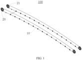
- FIG. 1 is a schematic structural diagram of a conveyor according to an embodiment of this application
- FIG. 2 is a schematic diagram of a partial structure of a conveyor according to an embodiment of this application.
- This utility model provides a conveyor 100, configured to convey an electrode plate.
- the conveyor 100 includes: a main body (not shown in the drawing), a guide mechanism 10, and a driving mechanism 20.
- the main body includes a transport space for accommodating the electrode plate.
- the guide mechanism 10 is disposed in the transport space.
- the guide mechanism 10 includes a traction rope 11.
- the traction rope 11 extends along a conveyance direction of the electrode plate and is connected to the electrode plate to bring the electrode plate to move.
- the driving mechanism 20 is drivingly connected to the traction rope 11, so as to drive the traction rope 11 to bring the electrode plate to move along the conveyance direction.
- the traction rope 11 may be a steel wire rope.
- the steel wire rope is of high rigidity and can reduce the risk of breaking off during the conveyance, and therefore, can serve to stably support the electrode plate.
- metal particles are prone to be generated by friction of the steel wire rope in motion. The metal particles are prone to adhere to and pollute the electrode plate in a high-temperature environment inside the oven. Therefore, the steel wire rope is coated with a non-metallic protection layer.
- the non-metallic protection layer not only protects the steel wire rope to some extent, but also prevents the electrode plate from being polluted by the metal particles generated during the movement, thereby ensuring high quality of the electrode plate.
- the traction rope 11 may be another similar rope structure other than the steel wire rope, or be directly a rope structure made of a non-metallic material, details of which are omitted here.
- the conveyor 100 is configured to convey the electrode plate in the oven. Therefore, the conveyor 100 is disposed inside the oven. That is, the transport space is located inside the oven.
- the traction rope 11 is fixedly connected to the electrode plate. As driven by the driving mechanism 20, the traction rope 11 may bring the electrode plate to move along a specified path.
- the traction rope 11 is of high flexibility, and therefore, can more smoothly bring the electrode plate to move along a specified path in the oven, thereby avoiding derailment or jamming during movement and conveying the electrode plate more smoothly and steadily in the oven.
- the traction rope 11 is fixed to the electrode plate by being indirectly connected to the electrode plate.
- the electrode plate may be fixed to the traction rope 11 by means of a connecting piece, thereby implementing stable connection between the electrode plate and the traction rope 11.
- the conveyor 100 includes a supporting roller 30 disposed under the traction rope 11 along a gravity direction.
- a guide slot 31 that extends along the transport space is made on the supporting roller 30.
- the traction rope 11 is disposed in the guide slot 31.
- the guide slot 31 is disposed along a circumferential direction of the supporting roller 30, and the guide slot 31 is in a middle-recessed shape.
- the supporting roller 30 is fixed onto an inner sidewall of the oven through an axle of the supporting roller, and can rotate around the axle.
- the supporting roller 30, serves to support the traction rope 11 and prevents the traction rope 11 from drooping due to its own gravity.
- the middle-recessed guide slot 31 prevents the traction rope 11 from coming out of the guide slot, and ensures stability of movement of the traction rope 11 in the guide slot 31.
- the supporting roller 30 is fixed onto the inner sidewall of the oven, and a plurality of supporting rollers are disposed along the conveyance direction.
- the guide slots 31 on all supporting rollers 30 jointly form a discontinuous guide path, so that the steel wire rope can bring the electrode plate to move along the guide path.
- the guide slot 31 can limit the steel wire rope to a specified position to prevent the steel wire rope from detaching from the supporting roller 30, and in turn, reduce the risk of breaking the electrode plate.
- the supporting roller 30 includes a first sub-roller and a second sub-roller.
- the first sub-roller and the second sub-roller are spaced apart in a horizontal plane that intersects the conveyance direction.
- the traction rope 11 includes a first sub-rope 111 and a second sub-rope 112.
- the first sub-rope 111 and the second sub-rope 112 are disposed in the guide slot 31 of the first sub-roller and the second sub-roller respectively.
- a conveyance space 113 for accommodating the electrode plate is formed between the first sub-rope and the second sub-rope.
- the guide mechanism 10 includes a connecting assembly 12. Two ends of the connecting assembly 12 are connected to the first sub-rope 111 and the second sub-rope 112 respectively, so as to fix the electrode plate in the conveyance space 113.
- the first sub-roller and the second sub-roller are disposed on two sides of the electrode plate respectively along a width direction of the electrode plate, and the first sub-rope 111 and the second sub-rope 112 are disposed on the two sides of the electrode plate along the width direction.
- the first sub-roller and the second sub-roller on the two sides of the electrode plate are fixed onto two opposite inner sidewalls in the oven respectively, and therefore, are disposed opposite to each other so that the first sub-rope 111 and the second sub-rope 112 can be accommodated in the guide slot 31 of the first sub-roller and the second sub-roller respectively.
- first sub-rollers and second sub-rollers are arranged along the conveyance direction of the electrode plate.
- first sub-roller and the second sub-roller are disposed corresponding to each other. Therefore, the traction rope 11 can extend along the arrangement path of the first sub-rollers and second sub-rollers, so as to bring the electrode plate to move along the path.
- a conveyance space 113 is formed between the first sub-rope 111 and the second sub-rope 112.
- the electrode plate is located in the conveyance space 113.
- the connecting assembly 12 is a conveyance rod. Two ends of the conveyance rod are fixedly connected to the first sub-rope 111 and the second sub-rope 112 respectively, and the conveyance rod is fixed to the electrode plate. In this way, when the first sub-rope 111 and the second sub-rope 112 move in the guide slot 31 as driven by the driving mechanism 20, the conveyance rod can bring the electrode plate to move synchronously.
- the connecting assembly 12 includes a connecting body 121 and at least one fixing portion 122 disposed on the connecting body 121.
- the fixing portion 122 is configured to fix the first sub-rope 111 and/or the second sub-rope 112, so as to connect the connecting assembly 12 and the traction rope 11.
- two fixing portions 122 are disposed at the two ends of the connecting body 121 respectively.
- the connecting body 121 is a rod body of the conveyance rod.
- the fixing portions 122 located at the two ends of the rod body are configured to fix the first sub-rope 111 and the second sub-rope 112.
- the two ends of the rod body may be fixedly connected to the first sub-rope 111 and the second sub-rope 112 by the fixing portion 122. That is, the first sub-rope 111 and the second sub-rope 112 are directly threaded through the fixing portion 122, as shown in FIG. 2 , so as to implement fixed connection between the rod body and the sub-ropes. This method makes the connection more stable.
- the two ends of the fixing portion 122 are chamfered, so that the fixing portion 122 forms a trapezoidal structure. In this way, the fixing portion 122 can pass between the supporting roller 30 and the pressure roller 40 that corresponds to the supporting roller, and avoid jamming caused when the fixing portion 122 passes between the supporting roller 30 and the pressure roller 40.
- FIG. 3 is a schematic diagram of a partial structure of a conveyor according to another embodiment of this application.
- the fixing portion 122 is structured as a clamping piece and is configured to clamp the first sub-rope 111 and/or the second sub-rope 112.
- the clamping piece includes two plate-shaped fittings spaced apart.
- a fixing position is formed between the two plate-shaped fittings.
- the two plate-shaped fittings can move toward each other or away from each other to change the size of the fixing position.
- the fixing position may be configured to accommodate the traction rope 11.
- the clamping piece can clamp and fix the first sub-rope 111 and the second sub-rope 112 separately to implement the connection between the electrode plate and the conveyance rod, thereby bringing the electrode plate to move.
- the clamping piece may release the first sub-rope 111 and the second sub-rope 112 to separate the electrode plate from the traction rope, thereby being more flexible and convenient.
- the conveyor 100 includes a pressure roller 40.
- the pressure roller 40 is disposed corresponding to the supporting roller 30.
- a limiting space is defined between the pressure roller and the supporting roller.
- the traction rope 11 is disposed in the limiting space.
- the pressure roller 40 is fixed onto an inner sidewall of the oven through an axle of the pressure roller, and can rotate around the axle.
- the pressure roller 40 is disposed above the supporting roller 30 along the gravity direction, and the pressure roller 40 is disposed in one-to-one correspondence with the supporting roller 30.
- a limiting space is formed between the pressure roller 40 and the corresponding supporting roller 30 in each set along the gravity direction.
- the first sub-rope 111 and the second sub-rope 112 can be positioned in the limiting space.
- the first sub-rope 111 and the second sub-rope 112 move in the guide slot 31 on the corresponding supporting roller 30, the first sub-rope 111 and the second sub-rope 112 may be detached from the guide slot 31 along the width direction of the electrode plate, thereby resulting in derailment.
- the derailment of the first sub-rope 111 and the second sub-rope 112 will stress the electrode plate nonuniformly during conveyance, thereby leading to breakage of the electrode plate.
- the pressure roller 40 After the pressure roller 40 is disposed, the pressure roller 40 generates a downward pressure on the first sub-rope 111 and the second sub-rope 112, and limits the first sub-rope 111 and the second sub-rope 112 to a position in the corresponding guide slot 31 along the gravity direction, thereby preventing the first sub-rope 111 and the second sub-rope 112 from detaching from the guide slot 31.
- the conveyor 100 includes a floating mechanism 50.
- the floating mechanism 50 includes a fastener 51 and an elastomer 52.
- the fastener 51 is fixedly connected to the main body.
- One end of the elastomer 52 is connected to the fastener 51, and another end of the elastomer is connected to the pressure roller 40, so as to change a distance between the pressure roller 40 and the supporting roller 30.
- the elastomer 52 may be a spring.
- the spring is connected between the fastener 51 and the pressure roller 40 to adjust the distance between the pressure roller 40 and the supporting roller 30.
- the elastomer 52 may be of another structure similar to a spring, details of which are omitted here.
- the fixing piece 51 is fixedly disposed on the inner wall of the oven.
- the elastomer 52 is connected between the fastener 51 and the pressure roller 40. Therefore, when the first sub-rope 111 and the second sub-rope 112 are located in the limiting space, because the mounting error is inevitable, the first sub-rope 111 and the second sub-rope 112 will float up and down during the movement.
- the elastomer 52 can adjust the distance between the pressure roller 40 and the supporting roller 30 according to the extent of upward and downward floating of the first sub-rope 111 and the second sub-rope 112, so that the first sub-rope 111 and the second sub-rope 112 can pass through the limiting space more smoothly.
- FIG. 4 is a schematic structural diagram of a conveyor according to an embodiment of this application
- FIG. 5 is a schematic structural diagram of a connecting assembly according to an embodiment of this application.
- the connecting assembly 12 includes a first subsection 123 and a second subsection 124 that are spaced apart.
- a clamping position 125 configured to clamp the electrode plate is formed between the first subsection 123 and the second subsection 124.
- the rod body of the conveyance rod is divided into a first subsection 123 and a second subsection 124.
- the first subsection 123 and the second subsection 124 are disposed apart along the gravity direction. In this way, a clamping position 125 is formed between the first subsection 123 and the second subsection 124, and the electrode plate is clamped in the clamping position 125, so that the connection between the electrode plate and the conveyance rod is more stable.
- the connecting assembly 12 includes an adjusting piece 126 connected between the first subsection 123 and the second subsection 124.
- the adjusting piece 126 is configured to adjust a distance between the first subsection 123 and the second subsection 124 in a gravity direction.
- the adjusting piece 126 is an adjusting bolt disposed between the first subsection 123 and the second subsection 124.
- the adjusting bolt can change the distance between the first subsection 123 and the second subsection 124 in the gravity direction.
- the clamping position 125 between the first subsection 123 and the second subsection 124 can adapt to electrode plates of different thicknesses, and prevent the electrode plate from being damaged by unduly tight clamping of the electrode plate by the first subsection 123 and the second subsection 124 or prevent detachment of the electrode plate caused by loose clamping.
- the dimensions of the clamping position 125 can be adjusted according to an actual thickness of the electrode plate, so as to clamp the electrode plate more firmly in the clamping position 125 and ensure stability of conveyance of the electrode plate.
- the driving mechanism 20 includes a driving roller 21 and a driving source (not shown in the drawing) that are drivingly connected.
- the traction rope 11 is wound around the driving roller 21 end-to-end along the conveyance direction, so as to move along the conveyance direction as driven by the driving source.
- two driving rollers 21 are disposed at a start end of the oven, and at a terminating end of the oven, separately.
- the two driving rollers are spaced along the width direction of the electrode plate.
- the first sub-rope 111 and the second sub-rope 112 each are wound around the driving rollers 21 end-to-end along the conveyance direction of the electrode plate, where the driving rollers are located at the start end and the terminating end of the oven respectively.
- the driving rollers 21 can rotate as driven by the driving source, thereby bringing the first sub-rope 111 and the second sub-rope 112 to move along the conveyance direction of the electrode plate and implementing conveyance of the electrode plate.
- the driving rollers 21 are usually disposed outside the oven and located at a start entrance and a terminating entrance of the oven respectively, and bring the first sub-rope 111 and the second sub-rope 112 to move.
- this application provides a baking device configured to dry an electrode plate.
- the baking device includes an oven and the conveyor 100 described above.
- the oven includes an accommodation space configured to dry the electrode plate, and the conveyor 100 is disposed in the accommodation space.
- the driving roller 21 rotates as driven by the driving source, thereby bringing the first sub-rope 111 and the second sub-rope 112 to move along the conveyance direction of the electrode plate. Inside the oven, the first sub-rope 111 and the second sub-rope 112 move along the guide slot 31 on the corresponding supporting roller 30.
- the pressure rollers 40 located above the first sub-rope 111 and the second sub-rope 112 can prevent the first sub-rope 111 and the second sub-rope 112 from detaching from the guide slot 31.
- the supporting roller 30 and the pressure roller 40 can roll over the fixing portion 122.
- the spring adjusts the distance between the supporting roller 30 and the pressure roller 40 in the gravity direction, so that the conveyance rod can pass through the limiting space smoothly.
- the conveyor 100 and the baking device in the foregoing embodiments have at least the following advantages:
Landscapes
- Engineering & Computer Science (AREA)
- Mechanical Engineering (AREA)
- General Engineering & Computer Science (AREA)
- Textile Engineering (AREA)
- Tunnel Furnaces (AREA)
- Transmission Devices (AREA)
- Rollers For Roller Conveyors For Transfer (AREA)
- Drying Of Solid Materials (AREA)
Abstract
Description
- This application claims priority to
Chinese Patent Application No. 202220424505.0, filed on February 28, 2022 - This application relates to the technical field of batteries, and in particular, to a conveyor and a baking device.
- During the coating of an electrode plate of a battery, the electrode plate needs to be dried in an oven. To ensure a good drying effect and high production efficiency, the oven is usually long in shape, and a plurality of guide rollers are disposed inside the oven. Therefore, a relatively large section of the electrode plate is located in the oven during the coating, thereby increasing the probability of breaking off the electrode plate inside the oven.
- When the electrode plate breaks inside the oven, due to the great length of the oven, a side door of the oven has to be opened, and the broken electrode plate is manually pulled out of the oven for connecting. In this process, because a part of the electrode plate is pulled out of the oven, the pulling force direction deviates from a movement direction of the electrode plate in the oven, thereby resulting in misalignment or even repeated breakage of the electrode plate. In addition, if the broken electrode plate is manually reconnected from a side of the oven, the production efficiency is not high.
- In view of the above situation, it is necessary to provide a conveyor and a baking device to solve the problem of inconvenience of handling breakage of an electrode plate occurring during coating and drying of the electrode plate.
- According to a first aspect, this application provides a conveyor, configured to convey an electrode plate and including: a main body, a guide mechanism, and a driving mechanism. The main body includes a transport space for accommodating the electrode plate. The guide mechanism is disposed in the transport space and includes a traction rope. The traction rope extends along a conveyance direction of the electrode plate and is connected to the electrode plate to bring the electrode plate to move. The driving mechanism is drivingly connected to the traction rope, so as to drive the traction rope to bring the electrode plate to move along the conveyance direction.
- In the technical solution in an embodiment of this application, the guide mechanism can fix the electrode plate and bring the electrode plate to move along the conveyance direction. In this way, the electrode plate can be automatically conveyed in the transport space to facilitate reconnection of the electrode plate that has broken. In addition, the traction rope is of high flexibility, and therefore, can more smoothly bring the electrode plate to move along a specified path in the oven, thereby avoiding derailment or jamming during movement and conveying the electrode plate more smoothly and steadily in the oven.
- In some embodiments, the conveyor includes a supporting roller disposed under the traction rope along a gravity direction. A guide slot that extends along the transport space is made on the supporting roller. The traction rope is disposed in the guide slot.
- In the technical solution of the foregoing embodiments of this application, the supporting roller serves to support the traction rope. The guide slot can limit the position of the traction rope on the horizontal plane along a direction perpendicular to the conveyance direction of the electrode plate, thereby preventing the traction rope from detaching from the supporting roller.
- In some embodiments, the supporting roller includes a first sub-roller and a second sub-roller. The first sub-roller and the second sub-roller are spaced apart in a horizontal plane that intersects the conveyance direction. The traction rope includes a first sub-rope and a second sub-rope. The first sub-rope and the second sub-rope are disposed in the guide slot of the first sub-roller and the second sub-roller respectively. A conveyance space for accommodating the electrode plate is formed between the first sub-rope and the second sub-rope. The guide mechanism includes a connecting assembly. Two ends of the connecting assembly are connected to the first sub-rope and the second sub-rope respectively, so as to fix the electrode plate in the conveyance space.
- In the technical solution of the foregoing embodiments of this application, the first sub-rope is accommodated in the guide slot of the first sub-roller, the second sub-rope is accommodated in the guide slot of the second sub-roller, and the electrode plate is fixed in the conveyance space between the first sub-rope and the second sub-rope. In this way, the electrode plate can be more stably disposed in the conveyance space, and the electrode plate is stressed more uniformly on both sides during movement and can be conveyed more smoothly.
- In some embodiments, the connecting assembly includes a connecting body and at least one fixing portion disposed on the connecting body. The fixing portion is configured to fix the first sub-rope and/or the second sub-rope, so as to connect the connecting assembly and the traction rope.
- In the technical solution of the foregoing embodiments of this application, the fixing portion can implement connection between the first sub-rope and/or the second sub-rope and the connecting assembly, so that the first sub-rope and/or the second sub-rope can be threaded through the fixing portion. In addition, the fixing portion is fixedly connected to the connecting assembly, and then the connecting assembly is connected to the electrode plate, so that the electrode plate can be conveyed through the traction ropes.
- In some embodiments, the fixing portion is structured as a clamping piece and is configured to clamp the first sub-rope and/or the second sub-rope.
- In the technical solution of the foregoing embodiments of this application, the clamping piece can more flexibly implement the connection between the first sub-rope and/or the second sub-rope and the connecting assembly. To convey the electrode plate, the clamping piece clamps the traction rope, so that the traction rope brings the electrode plate to run. Upon completion of conveying the electrode plate, the clamping piece releases the traction rope, so that the electrode plate can be removed from the guide mechanism.
- In some embodiments, the conveyor includes a pressure roller. The pressure roller is disposed corresponding to the supporting roller. A limiting space is defined between the pressure roller and the supporting roller. The traction rope is disposed in the limiting space.
- In the technical solution of the foregoing embodiments of this application, the pressure roller generates a downward pressure on the first sub-rope and the second sub-rope, and limits the first sub-rope and the second sub-rope to a position in the corresponding guide slot, thereby avoiding a jam or even breakage of the electrode plate caused by derailment when the first sub-rope or the second sub-rope is detached from the guide slot.
- In some embodiments, the conveyor includes a floating mechanism. The floating mechanism includes a fastener and an elastomer. The fastener is fixedly connected to the main body. One end of the elastomer is connected to the fastener, and another end of the elastomer is connected to the pressure roller, so as to change a distance between the pressure roller and the supporting roller.
- In the technical solution of the foregoing embodiments of this application, the elastomer can adjust the distance between the pressure roller and the supporting roller according to the extent of upward and downward floating of the first sub-rope and the second sub-rope, so that the first sub-rope and the second sub-rope can pass through the limiting space more smoothly.
- In some embodiments, the connecting assembly includes a first subsection and a second subsection that are spaced apart. A clamping position configured to clamp the electrode plate is formed between the first subsection and the second subsection.
- In the technical solution of the foregoing embodiments of this application, the electrode plate is clamped in the clamping position, so that the connection between the electrode plate and the connecting assembly is more stable.
- In some embodiments, the connecting assembly includes an adjusting piece connected between the first subsection and the second subsection. The adjusting piece is configured to adjust a distance between the first subsection and the second subsection in a gravity direction.
- In the technical solution of the foregoing embodiments of this application, by controlling the adjusting piece, the dimensions of the clamping position can be adjusted according to an actual thickness of the electrode plate, so as to clamp the electrode plate more firmly in the clamping position and ensure stability of conveyance of the electrode plate.
- In some embodiments, the driving mechanism includes a driving roller and a driving source that are drivingly connected. The traction rope is wound around the driving roller end-to-end along the conveyance direction, so as to move along the conveyance direction as driven by the driving source.
- In the technical solution of the foregoing embodiments of this application, the driving roller can rotate as driven by the driving source, thereby bringing the first sub-rope and the second sub-rope to move along the conveyance direction of the electrode plate and implementing conveyance of the electrode plate.
- According to a second aspect, this application provides a baking device. The baking device is configured to dry an electrode plate and includes an oven and the conveyor described above. An accommodation space configured to dry the electrode plate is provided in the oven. The conveyor is disposed in the accommodation space.
- In the conveyor and the baking device, the traction rope brings the electrode plate to move in the transport space. The traction rope is of high flexibility and can more smoothly bring the electrode plate to move in various complex environments such as an arcuate oven, thereby effectively avoiding derailment or jamming of the conveyor in the oven and conveying the electrode plate more smoothly in the oven.
- The foregoing description is merely an overview of the technical solutions of this application. Some specific embodiments of this application are described below illustratively to enable a clearer understanding of the technical solutions of this application, enable implementation of the technical solutions based on the subject-matter hereof, and make the foregoing and other objectives, features, and advantages of this application more evident and comprehensible.
- By reading the following detailed description of embodiments, a person of ordinary skill in the art becomes clearly aware of various other advantages and benefits. The drawings are merely intended to illustrate the embodiments, but not to limit this application. In all the drawings, the same reference numeral represents the same component. In the drawings:
-
FIG. 1 is a schematic structural diagram of a conveyor according to an embodiment of this application; -
FIG. 2 is a schematic diagram of a partial structure of a conveyor according to an embodiment of this application; -
FIG. 3 is a schematic diagram of a partial structure of a conveyor according to another embodiment of this application; -
FIG. 4 is a schematic diagram of a partial structure of a conveyor according to an embodiment of this application; and -
FIG. 5 is a schematic structural diagram of a connecting assembly according to an embodiment of this application. - 100. conveyor; 10. guide mechanism; 20. driving mechanism; 30. supporting roller; 40. pressure roller; 50. floating mechanism; 11. traction rope; 12. connecting assembly; 21. driving roller; 31. guide slot; 51. fastener; 52. elastomer; 111. first sub-rope; 112. second sub-rope; 113. conveyance space; 121. connecting body; 122. fixing portion; 123. first subsection; 124. second subsection; 125. clamping position; 126. adjusting piece.
- Some embodiments of the technical solutions of this application are described in detail below with reference to the drawings. The following embodiments are merely intended as examples to describe the technical solutions of this application more clearly, but not intended to limit the protection scope of this application.
- Unless otherwise defined, all technical and scientific terms used herein bear the same meanings as what is normally understood by a person skilled in the technical field of this application. The terms used herein are merely intended to describe specific embodiments but not to limit this application. The terms "include" and "contain" and any variations thereof used in the specification, claims, and brief description of drawings of this application are intended as non-exclusive inclusion.
- In the description of the embodiments of this application, the technical terms "first" and "second" are merely intended to distinguish between different items but not intended to indicate or imply relative importance or implicitly specify the number of the indicated technical features, specific order, or order of precedence. In the description of the embodiments of this application, unless otherwise expressly specified, "a plurality of" means two or more.
- Reference to an "embodiment" herein means that a specific feature, structure or characteristic described with reference to this embodiment may be included in at least one embodiment of this application. Reference to this term in different places in the specification does not necessarily represent the same embodiment, nor does it represent an independent or alternative embodiment in a mutually exclusive relationship with other embodiments. A person skilled in the art explicitly and implicitly understands that the embodiments described herein may be combined with other embodiments.
- In the description of embodiments of this application, the term "and/or" merely indicates a relationship between related items, and represents three possible relationships. For example, "A and/or B" may represent the following three circumstances: A alone, both A and B, and B alone. In addition, the character "/" herein generally indicates an "or" relationship between the item preceding the character and the item following the character.
- In the description of embodiments of this application, the term "a plurality of" means two or more (including two). Similarly, "a plurality of groups" means two or more groups (including two groups), and "a plurality of pieces" means two or more pieces (including two pieces).
- In the description of embodiments of this application, a direction or a positional relationship indicated by the terms such as "center", "longitudinal", "transverse", "length", "width", "thickness", "up", "down", "before", "after", "left", "right", "vertical", "horizontal", "top", "bottom", "in", "out", "clockwise", "counterclockwise", "axial", "radial", and "circumferential" is a direction or positional relationship based on the illustration in the drawings, and is merely intended for ease or brevity of description of embodiments of this application, but not intended to indicate or imply that the indicated device or component is necessarily located in the specified direction or constructed or operated in the specified direction. Therefore, such terms are not to be understood as a limitation on embodiments of this application.
- In the description of the embodiments of this application, unless otherwise expressly specified and defined, the technical terms such as "mounting", "concatenation", "connection", and "fixing" need to be understood in a broad sense, for example, understood as a fixed connection or a detachable connection or integrally formed; or understood as a mechanical connection or an electrical connection; understood as a direct connection, or an indirect connection implemented through an intermediary; or understood as internal communication between two components or interaction between two components. A person of ordinary skill in the art can understand the specific meanings of the terms in the embodiments of this application according to specific situations.
- Currently, as can be seen from the market trend, the application of power batteries is increasingly extensive. Power batteries are not only used in energy storage power systems such as hydro, thermal, wind, and solar power stations, but also widely used in electric means of transport such as electric bicycles, electric motorcycles, and electric vehicles, and used in many other fields such as military equipment and aerospace. The market demand for power batteries keeps soaring with the increase of the application fields of the power batteries.
- A production process of a power battery includes a coating step. In the coating step, a coated electrode plate of the battery needs to be dried in an oven before a next step of processing. However, in order to ensure a good drying effect and high production efficiency, the oven is usually in a long shape so that the electrode plate can be sufficiently dried. For this reason, during the movement of the electrode plate in the oven, the electrode plate is prone to break off due to a nonuniform force exerted on the electrode plate.
- To cope with the problem of breakage of the electrode plate, in a case that no auxiliary apparatus is in use, a conventional method is that an operator stops heating the oven. After the temperature in the oven drops to an appropriate level, the operator opens a side door of the oven after wearing labor protection clothes, and manually pulls the electrode plate in the oven from a side to pass the electrode plate through the oven. After the electrode plate is pulled out of the oven, a broken section of electrode plate is connected to another broken section by the operator, and is wound up through slow conveyance. This period is time-consuming. Specifically, it takes a long time to cool the oven, and to heat up the oven after restart. In addition, when a part of the electrode plate is manually pulled out of the oven, the pulling force direction is prone to deviate from the movement direction of the electrode plate in the oven, thereby resulting in misalignment or even repeated breakage of the electrode plate. In addition, due to a narrow space in the oven, the operation of manually pulling the electrode plate out of the oven is inconvenient, time-consuming, and labor-consuming.
- Therefore, currently, an auxiliary conveyance structure is disposed inside the oven. For example, a guide rail and a movable piece located in the guide rail are disposed, so that the movable piece brings the electrode plate to run along the guide rail. The inner space of some ovens is not completely flat and straight, but is arcuate. For the arcuate oven, in the prior art, a chain is usually used to bring the electrode plate to move in the oven. The chain is mounted in the oven in two manners. One of the mounting manners is to use a chain in conjunction with a guide rail, so that the chain moves in the guide rail to bring the electrode plate to move. In this manner, the mounting process is demanding. If the chain is not mounted properly, the chain is prone to jamming in the arcuate oven, thereby being adverse to practical applications. The other manner is to use sprockets to support the chain. In this manner, due to the heavy weight of the chain, the chain is prone to derail and result in breakage of the electrode plate, and the mounting process is complicated.
- Through research based on the above situation, the applicant hereof finds that the electrode plate may be pulled by a traction rope to move in the arcuate oven. Due to the low weight of the traction rope, the traction rope is not prone to derail during the movement, thereby more stably bringing the electrode plate to move. In addition, due to higher flexibility of the traction rope, the mounting of the traction rope inside the oven is more flexible and convenient. The traction rope can pull the electrode plate to move smoothly in a complicated environment.
- Based on the above considerations, in order to solve the problem that the conveyor is prone to derailment or jamming when bringing the electrode plate to move in an arcuate oven and results in low production efficiency and probable breakage of the electrode plate, the applicant has designed a conveyor and a baking device through in-depth research, in which a traction rope brings the electrode plate to move so that the electrode plate is conveyed more smoothly.
- Referring to
FIG. 1 andFIG. 2 ,FIG. 1 is a schematic structural diagram of a conveyor according to an embodiment of this application, andFIG. 2 is a schematic diagram of a partial structure of a conveyor according to an embodiment of this application. This utility model provides aconveyor 100, configured to convey an electrode plate. Theconveyor 100 includes: a main body (not shown in the drawing), aguide mechanism 10, and adriving mechanism 20. The main body includes a transport space for accommodating the electrode plate. Theguide mechanism 10 is disposed in the transport space. In addition, theguide mechanism 10 includes atraction rope 11. Thetraction rope 11 extends along a conveyance direction of the electrode plate and is connected to the electrode plate to bring the electrode plate to move. Thedriving mechanism 20 is drivingly connected to thetraction rope 11, so as to drive thetraction rope 11 to bring the electrode plate to move along the conveyance direction. - It is hereby noted that the
traction rope 11 may be a steel wire rope. The steel wire rope is of high rigidity and can reduce the risk of breaking off during the conveyance, and therefore, can serve to stably support the electrode plate. In addition, metal particles are prone to be generated by friction of the steel wire rope in motion. The metal particles are prone to adhere to and pollute the electrode plate in a high-temperature environment inside the oven. Therefore, the steel wire rope is coated with a non-metallic protection layer. The non-metallic protection layer not only protects the steel wire rope to some extent, but also prevents the electrode plate from being polluted by the metal particles generated during the movement, thereby ensuring high quality of the electrode plate. - Understandably, in some other embodiments, the
traction rope 11 may be another similar rope structure other than the steel wire rope, or be directly a rope structure made of a non-metallic material, details of which are omitted here. - Specifically, in this embodiment, the
conveyor 100 is configured to convey the electrode plate in the oven. Therefore, theconveyor 100 is disposed inside the oven. That is, the transport space is located inside the oven. Thetraction rope 11 is fixedly connected to the electrode plate. As driven by thedriving mechanism 20, thetraction rope 11 may bring the electrode plate to move along a specified path. Thetraction rope 11 is of high flexibility, and therefore, can more smoothly bring the electrode plate to move along a specified path in the oven, thereby avoiding derailment or jamming during movement and conveying the electrode plate more smoothly and steadily in the oven. - In addition, the
traction rope 11 is fixed to the electrode plate by being indirectly connected to the electrode plate. To be specific, the electrode plate may be fixed to thetraction rope 11 by means of a connecting piece, thereby implementing stable connection between the electrode plate and thetraction rope 11. - As shown in
FIG. 2 , theconveyor 100 includes a supportingroller 30 disposed under thetraction rope 11 along a gravity direction. Aguide slot 31 that extends along the transport space is made on the supportingroller 30. Thetraction rope 11 is disposed in theguide slot 31. - Specifically, the
guide slot 31 is disposed along a circumferential direction of the supportingroller 30, and theguide slot 31 is in a middle-recessed shape. The supportingroller 30 is fixed onto an inner sidewall of the oven through an axle of the supporting roller, and can rotate around the axle. When thetraction rope 11 is accommodated in theguide slot 31, the supportingroller 30, on the one hand, serves to support thetraction rope 11 and prevents thetraction rope 11 from drooping due to its own gravity. In addition, the middle-recessedguide slot 31 prevents thetraction rope 11 from coming out of the guide slot, and ensures stability of movement of thetraction rope 11 in theguide slot 31. - Further, in practical applications, the supporting
roller 30 is fixed onto the inner sidewall of the oven, and a plurality of supporting rollers are disposed along the conveyance direction. Theguide slots 31 on all supportingrollers 30 jointly form a discontinuous guide path, so that the steel wire rope can bring the electrode plate to move along the guide path. In addition, theguide slot 31 can limit the steel wire rope to a specified position to prevent the steel wire rope from detaching from the supportingroller 30, and in turn, reduce the risk of breaking the electrode plate. - In some embodiments, the supporting
roller 30 includes a first sub-roller and a second sub-roller. The first sub-roller and the second sub-roller are spaced apart in a horizontal plane that intersects the conveyance direction. Thetraction rope 11 includes afirst sub-rope 111 and asecond sub-rope 112. Thefirst sub-rope 111 and thesecond sub-rope 112 are disposed in theguide slot 31 of the first sub-roller and the second sub-roller respectively. Aconveyance space 113 for accommodating the electrode plate is formed between the first sub-rope and the second sub-rope. Theguide mechanism 10 includes a connectingassembly 12. Two ends of the connectingassembly 12 are connected to thefirst sub-rope 111 and thesecond sub-rope 112 respectively, so as to fix the electrode plate in theconveyance space 113. - Specifically in this embodiment, the first sub-roller and the second sub-roller are disposed on two sides of the electrode plate respectively along a width direction of the electrode plate, and the
first sub-rope 111 and thesecond sub-rope 112 are disposed on the two sides of the electrode plate along the width direction. The first sub-roller and the second sub-roller on the two sides of the electrode plate are fixed onto two opposite inner sidewalls in the oven respectively, and therefore, are disposed opposite to each other so that thefirst sub-rope 111 and thesecond sub-rope 112 can be accommodated in theguide slot 31 of the first sub-roller and the second sub-roller respectively. - Further, a plurality of sets of first sub-rollers and second sub-rollers are arranged along the conveyance direction of the electrode plate. In each set, the first sub-roller and the second sub-roller are disposed corresponding to each other. Therefore, the
traction rope 11 can extend along the arrangement path of the first sub-rollers and second sub-rollers, so as to bring the electrode plate to move along the path. - A
conveyance space 113 is formed between thefirst sub-rope 111 and thesecond sub-rope 112. The electrode plate is located in theconveyance space 113. In addition, the connectingassembly 12 is a conveyance rod. Two ends of the conveyance rod are fixedly connected to thefirst sub-rope 111 and thesecond sub-rope 112 respectively, and the conveyance rod is fixed to the electrode plate. In this way, when thefirst sub-rope 111 and thesecond sub-rope 112 move in theguide slot 31 as driven by thedriving mechanism 20, the conveyance rod can bring the electrode plate to move synchronously. - In some embodiments, the connecting
assembly 12 includes a connectingbody 121 and at least one fixingportion 122 disposed on the connectingbody 121. The fixingportion 122 is configured to fix thefirst sub-rope 111 and/or thesecond sub-rope 112, so as to connect the connectingassembly 12 and thetraction rope 11. - Specifically in this embodiment, two fixing
portions 122 are disposed at the two ends of the connectingbody 121 respectively. The connectingbody 121 is a rod body of the conveyance rod. The fixingportions 122 located at the two ends of the rod body are configured to fix thefirst sub-rope 111 and thesecond sub-rope 112. - Further, the two ends of the rod body may be fixedly connected to the
first sub-rope 111 and thesecond sub-rope 112 by the fixingportion 122. That is, thefirst sub-rope 111 and thesecond sub-rope 112 are directly threaded through the fixingportion 122, as shown inFIG. 2 , so as to implement fixed connection between the rod body and the sub-ropes. This method makes the connection more stable. - In addition, the two ends of the fixing
portion 122 are chamfered, so that the fixingportion 122 forms a trapezoidal structure. In this way, the fixingportion 122 can pass between the supportingroller 30 and thepressure roller 40 that corresponds to the supporting roller, and avoid jamming caused when the fixingportion 122 passes between the supportingroller 30 and thepressure roller 40. - Referring to
FIG. 3, FIG. 3 is a schematic diagram of a partial structure of a conveyor according to another embodiment of this application. In some embodiments, the fixingportion 122 is structured as a clamping piece and is configured to clamp thefirst sub-rope 111 and/or thesecond sub-rope 112. Specifically, the clamping piece includes two plate-shaped fittings spaced apart. A fixing position is formed between the two plate-shaped fittings. The two plate-shaped fittings can move toward each other or away from each other to change the size of the fixing position. The fixing position may be configured to accommodate thetraction rope 11. To clamp thetraction rope 11, thetraction rope 11 is placed in the fixing position, and the two plate-shaped fittings are caused to move toward each other until thetraction rope 11 is clamped and fixed. To unclamp thetraction rope 11, the two plate-shaped fittings are just caused to move away from each other to enlarge the fixing position between the two plate-shaped fittings, so that thetraction rope 11 is released from between the two plate-shaped fittings. - During the conveyance of the electrode plate in the oven, the clamping piece can clamp and fix the
first sub-rope 111 and thesecond sub-rope 112 separately to implement the connection between the electrode plate and the conveyance rod, thereby bringing the electrode plate to move. When the electrode plate stops moving or needs to undergo another operation, the clamping piece may release thefirst sub-rope 111 and thesecond sub-rope 112 to separate the electrode plate from the traction rope, thereby being more flexible and convenient. - Referring to
FIG. 2 again, in some embodiments, theconveyor 100 includes apressure roller 40. Thepressure roller 40 is disposed corresponding to the supportingroller 30. A limiting space is defined between the pressure roller and the supporting roller. Thetraction rope 11 is disposed in the limiting space. - Specifically, the
pressure roller 40 is fixed onto an inner sidewall of the oven through an axle of the pressure roller, and can rotate around the axle. In addition, thepressure roller 40 is disposed above the supportingroller 30 along the gravity direction, and thepressure roller 40 is disposed in one-to-one correspondence with the supportingroller 30. A limiting space is formed between thepressure roller 40 and the corresponding supportingroller 30 in each set along the gravity direction. Thefirst sub-rope 111 and thesecond sub-rope 112 can be positioned in the limiting space. - When the
first sub-rope 111 and thesecond sub-rope 112 move in theguide slot 31 on the corresponding supportingroller 30, thefirst sub-rope 111 and thesecond sub-rope 112 may be detached from theguide slot 31 along the width direction of the electrode plate, thereby resulting in derailment. The derailment of thefirst sub-rope 111 and thesecond sub-rope 112 will stress the electrode plate nonuniformly during conveyance, thereby leading to breakage of the electrode plate. - After the
pressure roller 40 is disposed, thepressure roller 40 generates a downward pressure on thefirst sub-rope 111 and thesecond sub-rope 112, and limits thefirst sub-rope 111 and thesecond sub-rope 112 to a position in thecorresponding guide slot 31 along the gravity direction, thereby preventing thefirst sub-rope 111 and thesecond sub-rope 112 from detaching from theguide slot 31. - In some embodiments, the
conveyor 100 includes a floatingmechanism 50. The floatingmechanism 50 includes afastener 51 and anelastomer 52. Thefastener 51 is fixedly connected to the main body. One end of theelastomer 52 is connected to thefastener 51, and another end of the elastomer is connected to thepressure roller 40, so as to change a distance between thepressure roller 40 and the supportingroller 30. - In a specific embodiment, the
elastomer 52 may be a spring. The spring is connected between thefastener 51 and thepressure roller 40 to adjust the distance between thepressure roller 40 and the supportingroller 30. Understandably, theelastomer 52 may be of another structure similar to a spring, details of which are omitted here. - Specifically, the fixing
piece 51 is fixedly disposed on the inner wall of the oven. Theelastomer 52 is connected between thefastener 51 and thepressure roller 40. Therefore, when thefirst sub-rope 111 and thesecond sub-rope 112 are located in the limiting space, because the mounting error is inevitable, thefirst sub-rope 111 and thesecond sub-rope 112 will float up and down during the movement. Theelastomer 52 can adjust the distance between thepressure roller 40 and the supportingroller 30 according to the extent of upward and downward floating of thefirst sub-rope 111 and thesecond sub-rope 112, so that thefirst sub-rope 111 and thesecond sub-rope 112 can pass through the limiting space more smoothly. - Referring to
FIG. 4 and FIG. 5, FIG. 4 is a schematic structural diagram of a conveyor according to an embodiment of this application, andFIG. 5 is a schematic structural diagram of a connecting assembly according to an embodiment of this application. To fix the connectingassembly 12 to the electrode plate more firmly, the connectingassembly 12 includes afirst subsection 123 and asecond subsection 124 that are spaced apart. Aclamping position 125 configured to clamp the electrode plate is formed between thefirst subsection 123 and thesecond subsection 124. - Specifically, the rod body of the conveyance rod is divided into a
first subsection 123 and asecond subsection 124. Thefirst subsection 123 and thesecond subsection 124 are disposed apart along the gravity direction. In this way, aclamping position 125 is formed between thefirst subsection 123 and thesecond subsection 124, and the electrode plate is clamped in theclamping position 125, so that the connection between the electrode plate and the conveyance rod is more stable. - In some embodiments, the connecting
assembly 12 includes anadjusting piece 126 connected between thefirst subsection 123 and thesecond subsection 124. The adjustingpiece 126 is configured to adjust a distance between thefirst subsection 123 and thesecond subsection 124 in a gravity direction. - Specifically in this embodiment, the adjusting
piece 126 is an adjusting bolt disposed between thefirst subsection 123 and thesecond subsection 124. The adjusting bolt can change the distance between thefirst subsection 123 and thesecond subsection 124 in the gravity direction. In this way, theclamping position 125 between thefirst subsection 123 and thesecond subsection 124 can adapt to electrode plates of different thicknesses, and prevent the electrode plate from being damaged by unduly tight clamping of the electrode plate by thefirst subsection 123 and thesecond subsection 124 or prevent detachment of the electrode plate caused by loose clamping. - Therefore, by controlling the adjusting
piece 126, the dimensions of theclamping position 125 can be adjusted according to an actual thickness of the electrode plate, so as to clamp the electrode plate more firmly in theclamping position 125 and ensure stability of conveyance of the electrode plate. - Referring to
FIG. 1 again, in some embodiments, thedriving mechanism 20 includes a drivingroller 21 and a driving source (not shown in the drawing) that are drivingly connected. Thetraction rope 11 is wound around the drivingroller 21 end-to-end along the conveyance direction, so as to move along the conveyance direction as driven by the driving source. - Specifically, two driving
rollers 21 are disposed at a start end of the oven, and at a terminating end of the oven, separately. The two driving rollers are spaced along the width direction of the electrode plate. Thefirst sub-rope 111 and thesecond sub-rope 112 each are wound around the drivingrollers 21 end-to-end along the conveyance direction of the electrode plate, where the driving rollers are located at the start end and the terminating end of the oven respectively. The drivingrollers 21 can rotate as driven by the driving source, thereby bringing thefirst sub-rope 111 and thesecond sub-rope 112 to move along the conveyance direction of the electrode plate and implementing conveyance of the electrode plate. - Due to scanty space available in the oven, the driving
rollers 21 are usually disposed outside the oven and located at a start entrance and a terminating entrance of the oven respectively, and bring thefirst sub-rope 111 and thesecond sub-rope 112 to move. - Based on the same conception as the
conveyor 100 described in the preceding embodiments, this application provides a baking device configured to dry an electrode plate. The baking device includes an oven and theconveyor 100 described above. The oven includes an accommodation space configured to dry the electrode plate, and theconveyor 100 is disposed in the accommodation space. - In a practical implementation of this application, the driving
roller 21 rotates as driven by the driving source, thereby bringing thefirst sub-rope 111 and thesecond sub-rope 112 to move along the conveyance direction of the electrode plate. Inside the oven, thefirst sub-rope 111 and thesecond sub-rope 112 move along theguide slot 31 on the corresponding supportingroller 30. Thepressure rollers 40 located above thefirst sub-rope 111 and thesecond sub-rope 112 can prevent thefirst sub-rope 111 and thesecond sub-rope 112 from detaching from theguide slot 31. - When the conveyance rod passes between the supporting
roller 30 and thepressure roller 40, the supportingroller 30 and thepressure roller 40 can roll over the fixingportion 122. At the same time, the spring adjusts the distance between the supportingroller 30 and thepressure roller 40 in the gravity direction, so that the conveyance rod can pass through the limiting space smoothly. - The
conveyor 100 and the baking device in the foregoing embodiments have at least the following advantages: - (1) The
first sub-rope 111 and thesecond sub-rope 112 are of high flexibility, and can bring the electrode plate to move smoothly in a complicated environment inside an arcuate oven, thereby reducing the risk of the jam or derailment of theconveyor 100 and avoiding breakage of the electrode plate; - (2) The supporting
roller 30 serves to support thefirst sub-rope 111 and thesecond sub-rope 112, and prevents thefirst sub-rope 111 and thesecond sub-rope 112 from drooping due to gravity, thereby reducing the force exerted on thefirst sub-rope 111 and thesecond sub-rope 112; - (3) The
guide slot 31 on the supportingroller 30 can limit the positions of thefirst sub-rope 111 and thesecond sub-rope 112 along the width direction of the electrode plate, thereby avoiding breakage of the electrode plate caused by detachment of thefirst sub-rope 111 and thesecond sub-rope 112 from theguide slot 31 during movement; - (4) The clamping piece enables the conveyance rod to be connected to the
first sub-rope 111 and thesecond sub-rope 112 by means of clamping, thereby making the connection manner more flexible and facilitating disassembly; - (5) The
pressure roller 40 can generate a downward pressure on thefirst sub-rope 111 and thesecond sub-rope 112, and limit thefirst sub-rope 111 and thesecond sub-rope 112 to a position in theguide slot 31 along the gravity direction, thereby making thefirst sub-rope 111 and thesecond sub-rope 112 move more smoothly in theguide slot 31; - (6) The spring can flexibly adjust the distance between the supporting
roller 30 and thepressure roller 40, so that the fixingportion 122 can smoothly pass through the limiting space between the supporting roller and the pressure roller and enable smoother conveyance of the electrode plate; and - (7) A
clamping position 125 is formed between thefirst subsection 123 and thesecond subsection 124, so that the electrode plate can be fixed more flexibly according to the actual thickness of the electrode plate, and the electrode plate can be connected to the conveyance rod more firmly and prevented from detaching from the conveyance rod during conveyance. - Finally, it is hereby noted that the foregoing embodiments are merely intended to describe the technical solutions of this application but not to limit this application. Although this application has been described in detail with reference to the foregoing embodiments, a person of ordinary skill in the art understands that modifications may still be made to the technical solutions described in the foregoing embodiments, or equivalent replacements may still be made to some or all technical features in the technical solutions. Such modifications and equivalent replacements fall within the scope of the claims and specification hereof without making the essence of the corresponding technical solutions depart from the scope of the technical solutions of the embodiments of this application. Particularly, to the extent that no structural conflict exists, various technical features mentioned in different embodiments may be combined in any manner. This application is not limited to the specific embodiments disclosed herein, but includes all technical solutions falling within the scope of the claims.
Claims (11)
- A conveyor, configured to convey an electrode plate and comprising:a main body, wherein the main body comprises a transport space for accommodating the electrode plate;a guide mechanism, wherein the guide mechanism is disposed in the transport space and comprises a traction rope, and the traction rope extends along a conveyance direction of the electrode plate and is connected to the electrode plate to bring the electrode plate to move; anda driving mechanism, wherein the driving mechanism is drivingly connected to the traction rope, so as to drive the traction rope to bring the electrode plate to move along the conveyance direction.
- The conveyor according to claim 1, wherein the conveyor comprises a supporting roller disposed under the traction rope along a gravity direction, a guide slot that extends along the conveyance direction is made on the supporting roller, and the traction rope is disposed in the guide slot.
- The conveyor according to claim 2, wherein the supporting roller comprises a first sub-roller and a second sub-roller, and the first sub-roller and the second sub-roller are spaced apart in a horizontal plane that intersects the conveyance direction;the traction rope comprises a first sub-rope and a second sub-rope, the first sub-rope and the second sub-rope are disposed in the guide slot of the first sub-roller and the second sub-roller respectively, and a conveyance space for accommodating the electrode plate is formed between the first sub-rope and the second sub-rope; andthe guide mechanism comprises a connecting assembly, and two ends of the connecting assembly are connected to the first sub-rope and the second sub-rope respectively, so as to fix the electrode plate in the conveyance space.
- The conveyor according to claim 3, wherein the connecting assembly comprises a connecting body and at least one fixing portion disposed on the connecting body, and the fixing portion is configured to fix the first sub-rope and/or the second sub-rope, so as to connect the connecting assembly and the traction rope.
- The conveyor according to claim 4, wherein the fixing portion is structured as a clamping piece and is configured to clamp the first sub-rope and/or the second sub-rope.
- The conveyor according to any one of claims 2 to 5, wherein the conveyor comprises a pressure roller, the pressure roller is disposed corresponding to the supporting roller, a limiting space is defined between the pressure roller and the supporting roller, and the traction rope is disposed in the limiting space.
- The conveyor according to claim 6, wherein the conveyor comprises a floating mechanism, and the floating mechanism comprises:a fastener, fixedly connected to the main body; andan elastomer, wherein one end of the elastomer is connected to the fastener, and another end of the elastomer is connected to the pressure roller, so as to change a distance between the pressure roller and the supporting roller.
- The conveyor according to any one of claims 3 to 5, wherein the connecting assembly comprises a first subsection and a second subsection that are spaced apart, and a clamping position configured to clamp the electrode plate is formed between the first subsection and the second subsection.
- The conveyor according to claim 8, wherein the connecting assembly comprises an adjusting piece connected between the first subsection and the second subsection, and the adjusting piece is configured to adjust a distance between the first subsection and the second subsection in a gravity direction.
- The conveyor according to any one of claims 1 to 9, wherein the driving mechanism comprises a driving roller and a driving source that are drivingly connected, and the traction rope is wound around the driving roller end-to-end along the conveyance direction, so as to move along the conveyance direction as driven by the driving source.
- A baking device, configured to dry an electrode plate and comprising:an oven, wherein an accommodation space configured to dry the electrode plate is provided in the oven; andthe conveyor according to any one of claims 1 to 10, wherein the conveyor is disposed in the accommodation space.
Applications Claiming Priority (2)
| Application Number | Priority Date | Filing Date | Title |
|---|---|---|---|
| CN202220424505.0U CN217172649U (en) | 2022-02-28 | 2022-02-28 | Threading device and baking equipment |
| PCT/CN2022/131126 WO2023160018A1 (en) | 2022-02-28 | 2022-11-10 | Belt threading device and baking apparatus |
Publications (3)
| Publication Number | Publication Date |
|---|---|
| EP4257525A1 true EP4257525A1 (en) | 2023-10-11 |
| EP4257525A4 EP4257525A4 (en) | 2024-10-02 |
| EP4257525B1 EP4257525B1 (en) | 2025-05-21 |
Family
ID=82739972
Family Applications (1)
| Application Number | Title | Priority Date | Filing Date |
|---|---|---|---|
| EP22902473.2A Active EP4257525B1 (en) | 2022-02-28 | 2022-11-10 | Belt threading device and baking apparatus |
Country Status (7)
| Country | Link |
|---|---|
| US (1) | US12000654B2 (en) |
| EP (1) | EP4257525B1 (en) |
| CN (1) | CN217172649U (en) |
| ES (1) | ES3037695T3 (en) |
| HU (1) | HUE072275T2 (en) |
| PL (1) | PL4257525T3 (en) |
| WO (1) | WO2023160018A1 (en) |
Families Citing this family (4)
| Publication number | Priority date | Publication date | Assignee | Title |
|---|---|---|---|---|
| CN217172649U (en) * | 2022-02-28 | 2022-08-12 | 宁德时代新能源科技股份有限公司 | Threading device and baking equipment |
| CN115475851B (en) * | 2022-09-14 | 2025-03-14 | 四川嘉拓智能设备有限公司 | A single wire threading device |
| CN115744427A (en) * | 2022-10-31 | 2023-03-07 | 广东利元亨智能装备股份有限公司 | Automatic tape threading equipment, oven, coating machine and automatic tape threading method |
| EP4425641A4 (en) * | 2023-01-03 | 2025-03-05 | Contemporary Amperex Technology (Hong Kong) Limited | THREADING DEVICE AND METHOD FOR RECONNECTING BAND USING THREADING DEVICE |
Family Cites Families (18)
| Publication number | Priority date | Publication date | Assignee | Title |
|---|---|---|---|---|
| US467289A (en) * | 1892-01-19 | Hoisting apparatus | ||
| US142003A (en) * | 1873-08-19 | Improvement in reels for ovens | ||
| US900749A (en) * | 1908-02-08 | 1908-10-13 | William B Leonard | Amusement device. |
| US1753914A (en) * | 1928-01-09 | 1930-04-08 | Horace A Bodge | Bake oven |
| BE758783A (en) * | 1969-11-10 | 1971-05-10 | Monteponi & Montevecchio S P A | APPARATUS FOR DETACHING CATHODES, ESPECIALLY ALUMINUM, FROM METAL SHEETS FORMED BY ELECTROLYTIC DEPOSIT |
| DE3122624A1 (en) * | 1981-06-06 | 1982-12-30 | Friedrich Wilhelm Paurat | SHAFTS CONVEYOR FOR MINING COMPANIES |
| DE19917368C2 (en) * | 1999-04-16 | 2001-10-11 | Rheinische Braunkohlenw Ag | Continuous conveyor |
| US7143528B2 (en) * | 2000-09-24 | 2006-12-05 | 3M Innovative Properties Company | Dry converting process and apparatus |
| WO2014087473A1 (en) * | 2012-12-03 | 2014-06-12 | 新神戸電機株式会社 | Electrode plate drying device and electrode plate drying method |
| CN104838523B (en) * | 2012-12-05 | 2016-08-24 | 日产自动车株式会社 | Diaphragm conveying device for electric device and conveying method thereof |
| CN103495537B (en) * | 2013-09-03 | 2015-07-22 | 浙江金开来新能源科技有限公司 | Coating machine drying oven and coating machine including same |
| CN206046433U (en) | 2016-06-16 | 2017-03-29 | 深圳市新嘉拓自动化技术有限公司 | Coating machine oven automatic threading tape drive |
| WO2019060948A1 (en) * | 2017-09-29 | 2019-04-04 | Montan Materials Handling Pty Ltd | Rope conveyor system |
| KR102537218B1 (en) * | 2018-01-08 | 2023-05-26 | 주식회사 엘지에너지솔루션 | Apparatus and method for transporting electrode sheet |
| CN112304070A (en) * | 2019-11-08 | 2021-02-02 | 宁德时代新能源科技股份有限公司 | Belt threading device, secondary battery pole piece baking equipment, and belt threading method |
| BE1027853B1 (en) * | 2019-12-12 | 2021-07-13 | Thyssenkrupp Ag | Conveyor belt system with roller support for a conveyor belt as well as process and use |
| CN214234797U (en) | 2020-11-19 | 2021-09-21 | 江西嘉拓智能设备有限公司 | Auxiliary structure for belt threading of drying oven of coating machine |
| CN217172649U (en) * | 2022-02-28 | 2022-08-12 | 宁德时代新能源科技股份有限公司 | Threading device and baking equipment |
-
2022
- 2022-02-28 CN CN202220424505.0U patent/CN217172649U/en active Active
- 2022-11-10 HU HUE22902473A patent/HUE072275T2/en unknown
- 2022-11-10 PL PL22902473.2T patent/PL4257525T3/en unknown
- 2022-11-10 WO PCT/CN2022/131126 patent/WO2023160018A1/en not_active Ceased
- 2022-11-10 ES ES22902473T patent/ES3037695T3/en active Active
- 2022-11-10 EP EP22902473.2A patent/EP4257525B1/en active Active
-
2023
- 2023-08-09 US US18/231,796 patent/US12000654B2/en active Active
Also Published As
| Publication number | Publication date |
|---|---|
| CN217172649U (en) | 2022-08-12 |
| EP4257525B1 (en) | 2025-05-21 |
| PL4257525T3 (en) | 2025-10-13 |
| US20230384034A1 (en) | 2023-11-30 |
| WO2023160018A1 (en) | 2023-08-31 |
| EP4257525A4 (en) | 2024-10-02 |
| ES3037695T3 (en) | 2025-10-06 |
| HUE072275T2 (en) | 2025-11-28 |
| US12000654B2 (en) | 2024-06-04 |
Similar Documents
| Publication | Publication Date | Title |
|---|---|---|
| EP4257525A1 (en) | Belt threading device and baking apparatus | |
| TWI750378B (en) | Carrying support and surface treatment device using the same | |
| CN113097329B (en) | Battery string production equipment and battery string production method | |
| CN217147452U (en) | Conveyor and battery production system | |
| CN111599891A (en) | Stacking conveying equipment and stacking conveying method | |
| WO2022089042A1 (en) | Conveying apparatus, conveying system, and printing device | |
| WO2025030719A1 (en) | Feeding device and feeding system | |
| CN104400274A (en) | A fully automatic welding line for single and double-headed power batteries | |
| CN216231788U (en) | Automatic change device of vehicular unmanned aerial vehicle air park battery | |
| CN216644906U (en) | Adjustable vertical material tray | |
| CN213445021U (en) | Electricity core unloading transfer device | |
| CN217478214U (en) | Battery piece conveying mechanism and battery piece feedway | |
| EP4235072B1 (en) | Conveyor | |
| CN117246814B (en) | Cloth belt conveying device and cloth processing equipment | |
| CN212768363U (en) | Automatic lifter for battery conveying line | |
| CN210735507U (en) | Mounting machine suitable for limited space | |
| CN209922161U (en) | Copper starting sheet workbin conveyer | |
| CN210312083U (en) | Lamp wick fixing and conveying device of LED lamp wick arranging and placing equipment | |
| CN221970536U (en) | Power rollers, roller assemblies and conveyor lines | |
| CN220009012U (en) | Conveying device of bottom pasting machine | |
| CN222225280U (en) | Transfer device | |
| CN221164939U (en) | Feeding device for manufacturing chromium plating thin plate | |
| CN218087495U (en) | Anchor clamps dispatch system and toast line | |
| CN223875792U (en) | Rolling equipment | |
| CN220389174U (en) | Lithium battery clamping device |
Legal Events
| Date | Code | Title | Description |
|---|---|---|---|
| STAA | Information on the status of an ep patent application or granted ep patent |
Free format text: STATUS: UNKNOWN |
|
| STAA | Information on the status of an ep patent application or granted ep patent |
Free format text: STATUS: THE INTERNATIONAL PUBLICATION HAS BEEN MADE |
|
| PUAI | Public reference made under article 153(3) epc to a published international application that has entered the european phase |
Free format text: ORIGINAL CODE: 0009012 |
|
| STAA | Information on the status of an ep patent application or granted ep patent |
Free format text: STATUS: REQUEST FOR EXAMINATION WAS MADE |
|
| 17P | Request for examination filed |
Effective date: 20230614 |
|
| AK | Designated contracting states |
Kind code of ref document: A1 Designated state(s): AL AT BE BG CH CY CZ DE DK EE ES FI FR GB GR HR HU IE IS IT LI LT LU LV MC ME MK MT NL NO PL PT RO RS SE SI SK SM TR |
|
| A4 | Supplementary search report drawn up and despatched |
Effective date: 20240830 |
|
| RAP1 | Party data changed (applicant data changed or rights of an application transferred) |
Owner name: CONTEMPORARY AMPEREX TECHNOLOGY(HONG KONG) LIMITED |
|
| RIC1 | Information provided on ipc code assigned before grant |
Ipc: F27B 9/24 20060101ALI20240826BHEP Ipc: F26B 13/00 20060101ALI20240826BHEP Ipc: F26B 25/02 20060101ALI20240826BHEP Ipc: H01M 4/04 20060101ALI20240826BHEP Ipc: B05B 3/02 20060101ALI20240826BHEP Ipc: F26B 25/00 20060101ALI20240826BHEP Ipc: B65H 20/00 20060101AFI20240826BHEP |
|
| GRAP | Despatch of communication of intention to grant a patent |
Free format text: ORIGINAL CODE: EPIDOSNIGR1 |
|
| STAA | Information on the status of an ep patent application or granted ep patent |
Free format text: STATUS: GRANT OF PATENT IS INTENDED |
|
| GRAS | Grant fee paid |
Free format text: ORIGINAL CODE: EPIDOSNIGR3 |
|
| RIC1 | Information provided on ipc code assigned before grant |
Ipc: F27B 9/24 20060101ALI20250312BHEP Ipc: F26B 13/00 20060101ALI20250312BHEP Ipc: F26B 25/02 20060101ALI20250312BHEP Ipc: H01M 4/04 20060101ALI20250312BHEP Ipc: B05B 3/02 20060101ALI20250312BHEP Ipc: F26B 25/00 20060101ALI20250312BHEP Ipc: B65H 20/00 20060101AFI20250312BHEP |
|
| GRAA | (expected) grant |
Free format text: ORIGINAL CODE: 0009210 |
|
| STAA | Information on the status of an ep patent application or granted ep patent |
Free format text: STATUS: THE PATENT HAS BEEN GRANTED |
|
| DAV | Request for validation of the european patent (deleted) | ||
| DAX | Request for extension of the european patent (deleted) | ||
| INTG | Intention to grant announced |
Effective date: 20250320 |
|
| AK | Designated contracting states |
Kind code of ref document: B1 Designated state(s): AL AT BE BG CH CY CZ DE DK EE ES FI FR GB GR HR HU IE IS IT LI LT LU LV MC ME MK MT NL NO PL PT RO RS SE SI SK SM TR |
|
| REG | Reference to a national code |
Ref country code: GB Ref legal event code: FG4D |
|
| P01 | Opt-out of the competence of the unified patent court (upc) registered |
Free format text: CASE NUMBER: APP_19279/2025 Effective date: 20250422 |
|
| REG | Reference to a national code |
Ref country code: CH Ref legal event code: EP |
|
| REG | Reference to a national code |
Ref country code: DE Ref legal event code: R096 Ref document number: 602022015082 Country of ref document: DE |
|
| REG | Reference to a national code |
Ref country code: IE Ref legal event code: FG4D |
|
| REG | Reference to a national code |
Ref country code: NL Ref legal event code: MP Effective date: 20250521 |
|
| REG | Reference to a national code |
Ref country code: ES Ref legal event code: FG2A Ref document number: 3037695 Country of ref document: ES Kind code of ref document: T3 Effective date: 20251006 |
|
| PG25 | Lapsed in a contracting state [announced via postgrant information from national office to epo] |
Ref country code: FI Free format text: LAPSE BECAUSE OF FAILURE TO SUBMIT A TRANSLATION OF THE DESCRIPTION OR TO PAY THE FEE WITHIN THE PRESCRIBED TIME-LIMIT Effective date: 20250521 Ref country code: PT Free format text: LAPSE BECAUSE OF FAILURE TO SUBMIT A TRANSLATION OF THE DESCRIPTION OR TO PAY THE FEE WITHIN THE PRESCRIBED TIME-LIMIT Effective date: 20250922 |
|
| REG | Reference to a national code |
Ref country code: LT Ref legal event code: MG9D |
|
| PG25 | Lapsed in a contracting state [announced via postgrant information from national office to epo] |
Ref country code: NO Free format text: LAPSE BECAUSE OF FAILURE TO SUBMIT A TRANSLATION OF THE DESCRIPTION OR TO PAY THE FEE WITHIN THE PRESCRIBED TIME-LIMIT Effective date: 20250821 Ref country code: GR Free format text: LAPSE BECAUSE OF FAILURE TO SUBMIT A TRANSLATION OF THE DESCRIPTION OR TO PAY THE FEE WITHIN THE PRESCRIBED TIME-LIMIT Effective date: 20250822 |
|
| PG25 | Lapsed in a contracting state [announced via postgrant information from national office to epo] |
Ref country code: NL Free format text: LAPSE BECAUSE OF FAILURE TO SUBMIT A TRANSLATION OF THE DESCRIPTION OR TO PAY THE FEE WITHIN THE PRESCRIBED TIME-LIMIT Effective date: 20250521 |
|
| PG25 | Lapsed in a contracting state [announced via postgrant information from national office to epo] |
Ref country code: BG Free format text: LAPSE BECAUSE OF FAILURE TO SUBMIT A TRANSLATION OF THE DESCRIPTION OR TO PAY THE FEE WITHIN THE PRESCRIBED TIME-LIMIT Effective date: 20250521 |
|
| PG25 | Lapsed in a contracting state [announced via postgrant information from national office to epo] |
Ref country code: HR Free format text: LAPSE BECAUSE OF FAILURE TO SUBMIT A TRANSLATION OF THE DESCRIPTION OR TO PAY THE FEE WITHIN THE PRESCRIBED TIME-LIMIT Effective date: 20250521 |
|
| PG25 | Lapsed in a contracting state [announced via postgrant information from national office to epo] |
Ref country code: RS Free format text: LAPSE BECAUSE OF FAILURE TO SUBMIT A TRANSLATION OF THE DESCRIPTION OR TO PAY THE FEE WITHIN THE PRESCRIBED TIME-LIMIT Effective date: 20250821 |
|
| PG25 | Lapsed in a contracting state [announced via postgrant information from national office to epo] |
Ref country code: IS Free format text: LAPSE BECAUSE OF FAILURE TO SUBMIT A TRANSLATION OF THE DESCRIPTION OR TO PAY THE FEE WITHIN THE PRESCRIBED TIME-LIMIT Effective date: 20250921 |
|
| PG25 | Lapsed in a contracting state [announced via postgrant information from national office to epo] |
Ref country code: LV Free format text: LAPSE BECAUSE OF FAILURE TO SUBMIT A TRANSLATION OF THE DESCRIPTION OR TO PAY THE FEE WITHIN THE PRESCRIBED TIME-LIMIT Effective date: 20250521 |
|
| REG | Reference to a national code |
Ref country code: HU Ref legal event code: AG4A Ref document number: E072275 Country of ref document: HU |
|
| PGFP | Annual fee paid to national office [announced via postgrant information from national office to epo] |
Ref country code: HU Payment date: 20251107 Year of fee payment: 4 |
|
| REG | Reference to a national code |
Ref country code: AT Ref legal event code: MK05 Ref document number: 1796603 Country of ref document: AT Kind code of ref document: T Effective date: 20250521 |
|
| PGFP | Annual fee paid to national office [announced via postgrant information from national office to epo] |
Ref country code: DE Payment date: 20251124 Year of fee payment: 4 |
|
| PG25 | Lapsed in a contracting state [announced via postgrant information from national office to epo] |
Ref country code: DK Free format text: LAPSE BECAUSE OF FAILURE TO SUBMIT A TRANSLATION OF THE DESCRIPTION OR TO PAY THE FEE WITHIN THE PRESCRIBED TIME-LIMIT Effective date: 20250521 Ref country code: SM Free format text: LAPSE BECAUSE OF FAILURE TO SUBMIT A TRANSLATION OF THE DESCRIPTION OR TO PAY THE FEE WITHIN THE PRESCRIBED TIME-LIMIT Effective date: 20250521 Ref country code: AT Free format text: LAPSE BECAUSE OF FAILURE TO SUBMIT A TRANSLATION OF THE DESCRIPTION OR TO PAY THE FEE WITHIN THE PRESCRIBED TIME-LIMIT Effective date: 20250521 |
|
| PG25 | Lapsed in a contracting state [announced via postgrant information from national office to epo] |
Ref country code: CZ Free format text: LAPSE BECAUSE OF FAILURE TO SUBMIT A TRANSLATION OF THE DESCRIPTION OR TO PAY THE FEE WITHIN THE PRESCRIBED TIME-LIMIT Effective date: 20250521 |
|
| PGFP | Annual fee paid to national office [announced via postgrant information from national office to epo] |
Ref country code: PL Payment date: 20251103 Year of fee payment: 4 |
|
| PG25 | Lapsed in a contracting state [announced via postgrant information from national office to epo] |
Ref country code: EE Free format text: LAPSE BECAUSE OF FAILURE TO SUBMIT A TRANSLATION OF THE DESCRIPTION OR TO PAY THE FEE WITHIN THE PRESCRIBED TIME-LIMIT Effective date: 20250521 |
|
| PG25 | Lapsed in a contracting state [announced via postgrant information from national office to epo] |
Ref country code: SK Free format text: LAPSE BECAUSE OF FAILURE TO SUBMIT A TRANSLATION OF THE DESCRIPTION OR TO PAY THE FEE WITHIN THE PRESCRIBED TIME-LIMIT Effective date: 20250521 |
|
| PG25 | Lapsed in a contracting state [announced via postgrant information from national office to epo] |
Ref country code: IT Free format text: LAPSE BECAUSE OF FAILURE TO SUBMIT A TRANSLATION OF THE DESCRIPTION OR TO PAY THE FEE WITHIN THE PRESCRIBED TIME-LIMIT Effective date: 20250521 |
|
| PGFP | Annual fee paid to national office [announced via postgrant information from national office to epo] |
Ref country code: ES Payment date: 20251202 Year of fee payment: 4 |
|
| REG | Reference to a national code |
Ref country code: DE Ref legal event code: R097 Ref document number: 602022015082 Country of ref document: DE |
|
| PG25 | Lapsed in a contracting state [announced via postgrant information from national office to epo] |
Ref country code: RO Free format text: LAPSE BECAUSE OF FAILURE TO SUBMIT A TRANSLATION OF THE DESCRIPTION OR TO PAY THE FEE WITHIN THE PRESCRIBED TIME-LIMIT Effective date: 20250521 |
|
| PLBE | No opposition filed within time limit |
Free format text: ORIGINAL CODE: 0009261 |
|
| STAA | Information on the status of an ep patent application or granted ep patent |
Free format text: STATUS: NO OPPOSITION FILED WITHIN TIME LIMIT |
|
| REG | Reference to a national code |
Ref country code: CH Ref legal event code: L10 Free format text: ST27 STATUS EVENT CODE: U-0-0-L10-L00 (AS PROVIDED BY THE NATIONAL OFFICE) Effective date: 20260402 |
|
| 26N | No opposition filed |
Effective date: 20260224 |