EP4257439A2 - Procédé de fonctionnement et dispositif de commande d'un fonctionnement motorisé d'une machine électrique d'un entraînement hybride doux d'un véhicule à moteur - Google Patents
Procédé de fonctionnement et dispositif de commande d'un fonctionnement motorisé d'une machine électrique d'un entraînement hybride doux d'un véhicule à moteur Download PDFInfo
- Publication number
- EP4257439A2 EP4257439A2 EP23187886.9A EP23187886A EP4257439A2 EP 4257439 A2 EP4257439 A2 EP 4257439A2 EP 23187886 A EP23187886 A EP 23187886A EP 4257439 A2 EP4257439 A2 EP 4257439A2
- Authority
- EP
- European Patent Office
- Prior art keywords
- energy
- vehicle
- motor
- motor vehicle
- electrical
- Prior art date
- Legal status (The legal status is an assumption and is not a legal conclusion. Google has not performed a legal analysis and makes no representation as to the accuracy of the status listed.)
- Pending
Links
- 238000000034 method Methods 0.000 title claims description 17
- 238000002485 combustion reaction Methods 0.000 claims abstract description 28
- 238000011017 operating method Methods 0.000 claims abstract description 19
- 238000004146 energy storage Methods 0.000 claims description 47
- 238000013210 evaluation model Methods 0.000 claims description 3
- 238000011156 evaluation Methods 0.000 claims 1
- 239000000446 fuel Substances 0.000 abstract description 9
- 239000007858 starting material Substances 0.000 description 12
- 230000001172 regenerating effect Effects 0.000 description 4
- 230000006870 function Effects 0.000 description 3
- 239000003990 capacitor Substances 0.000 description 2
- 238000010586 diagram Methods 0.000 description 2
- HBBGRARXTFLTSG-UHFFFAOYSA-N Lithium ion Chemical compound [Li+] HBBGRARXTFLTSG-UHFFFAOYSA-N 0.000 description 1
- 230000002457 bidirectional effect Effects 0.000 description 1
- 239000003344 environmental pollutant Substances 0.000 description 1
- 230000005284 excitation Effects 0.000 description 1
- 229910001416 lithium ion Inorganic materials 0.000 description 1
- 231100000719 pollutant Toxicity 0.000 description 1
- 238000011084 recovery Methods 0.000 description 1
- 239000007787 solid Substances 0.000 description 1
Images

Classifications
-
- B—PERFORMING OPERATIONS; TRANSPORTING
- B60—VEHICLES IN GENERAL
- B60W—CONJOINT CONTROL OF VEHICLE SUB-UNITS OF DIFFERENT TYPE OR DIFFERENT FUNCTION; CONTROL SYSTEMS SPECIALLY ADAPTED FOR HYBRID VEHICLES; ROAD VEHICLE DRIVE CONTROL SYSTEMS FOR PURPOSES NOT RELATED TO THE CONTROL OF A PARTICULAR SUB-UNIT
- B60W20/00—Control systems specially adapted for hybrid vehicles
- B60W20/10—Controlling the power contribution of each of the prime movers to meet required power demand
- B60W20/13—Controlling the power contribution of each of the prime movers to meet required power demand in order to stay within battery power input or output limits; in order to prevent overcharging or battery depletion
- B60W20/14—Controlling the power contribution of each of the prime movers to meet required power demand in order to stay within battery power input or output limits; in order to prevent overcharging or battery depletion in conjunction with braking regeneration
-
- B—PERFORMING OPERATIONS; TRANSPORTING
- B60—VEHICLES IN GENERAL
- B60K—ARRANGEMENT OR MOUNTING OF PROPULSION UNITS OR OF TRANSMISSIONS IN VEHICLES; ARRANGEMENT OR MOUNTING OF PLURAL DIVERSE PRIME-MOVERS IN VEHICLES; AUXILIARY DRIVES FOR VEHICLES; INSTRUMENTATION OR DASHBOARDS FOR VEHICLES; ARRANGEMENTS IN CONNECTION WITH COOLING, AIR INTAKE, GAS EXHAUST OR FUEL SUPPLY OF PROPULSION UNITS IN VEHICLES
- B60K6/00—Arrangement or mounting of plural diverse prime-movers for mutual or common propulsion, e.g. hybrid propulsion systems comprising electric motors and internal combustion engines ; Control systems therefor, i.e. systems controlling two or more prime movers, or controlling one of these prime movers and any of the transmission, drive or drive units Informative references: mechanical gearings with secondary electric drive F16H3/72; arrangements for handling mechanical energy structurally associated with the dynamo-electric machine H02K7/00; machines comprising structurally interrelated motor and generator parts H02K51/00; dynamo-electric machines not otherwise provided for in H02K see H02K99/00
- B60K6/20—Arrangement or mounting of plural diverse prime-movers for mutual or common propulsion, e.g. hybrid propulsion systems comprising electric motors and internal combustion engines ; Control systems therefor, i.e. systems controlling two or more prime movers, or controlling one of these prime movers and any of the transmission, drive or drive units Informative references: mechanical gearings with secondary electric drive F16H3/72; arrangements for handling mechanical energy structurally associated with the dynamo-electric machine H02K7/00; machines comprising structurally interrelated motor and generator parts H02K51/00; dynamo-electric machines not otherwise provided for in H02K see H02K99/00 the prime-movers consisting of electric motors and internal combustion engines, e.g. HEVs
- B60K6/42—Arrangement or mounting of plural diverse prime-movers for mutual or common propulsion, e.g. hybrid propulsion systems comprising electric motors and internal combustion engines ; Control systems therefor, i.e. systems controlling two or more prime movers, or controlling one of these prime movers and any of the transmission, drive or drive units Informative references: mechanical gearings with secondary electric drive F16H3/72; arrangements for handling mechanical energy structurally associated with the dynamo-electric machine H02K7/00; machines comprising structurally interrelated motor and generator parts H02K51/00; dynamo-electric machines not otherwise provided for in H02K see H02K99/00 the prime-movers consisting of electric motors and internal combustion engines, e.g. HEVs characterised by the architecture of the hybrid electric vehicle
- B60K6/48—Parallel type
- B60K6/485—Motor-assist type
-
- B—PERFORMING OPERATIONS; TRANSPORTING
- B60—VEHICLES IN GENERAL
- B60L—PROPULSION OF ELECTRICALLY-PROPELLED VEHICLES; SUPPLYING ELECTRIC POWER FOR AUXILIARY EQUIPMENT OF ELECTRICALLY-PROPELLED VEHICLES; ELECTRODYNAMIC BRAKE SYSTEMS FOR VEHICLES IN GENERAL; MAGNETIC SUSPENSION OR LEVITATION FOR VEHICLES; MONITORING OPERATING VARIABLES OF ELECTRICALLY-PROPELLED VEHICLES; ELECTRIC SAFETY DEVICES FOR ELECTRICALLY-PROPELLED VEHICLES
- B60L58/00—Methods or circuit arrangements for monitoring or controlling batteries or fuel cells, specially adapted for electric vehicles
- B60L58/10—Methods or circuit arrangements for monitoring or controlling batteries or fuel cells, specially adapted for electric vehicles for monitoring or controlling batteries
- B60L58/18—Methods or circuit arrangements for monitoring or controlling batteries or fuel cells, specially adapted for electric vehicles for monitoring or controlling batteries of two or more battery modules
- B60L58/20—Methods or circuit arrangements for monitoring or controlling batteries or fuel cells, specially adapted for electric vehicles for monitoring or controlling batteries of two or more battery modules having different nominal voltages
-
- B—PERFORMING OPERATIONS; TRANSPORTING
- B60—VEHICLES IN GENERAL
- B60W—CONJOINT CONTROL OF VEHICLE SUB-UNITS OF DIFFERENT TYPE OR DIFFERENT FUNCTION; CONTROL SYSTEMS SPECIALLY ADAPTED FOR HYBRID VEHICLES; ROAD VEHICLE DRIVE CONTROL SYSTEMS FOR PURPOSES NOT RELATED TO THE CONTROL OF A PARTICULAR SUB-UNIT
- B60W10/00—Conjoint control of vehicle sub-units of different type or different function
- B60W10/04—Conjoint control of vehicle sub-units of different type or different function including control of propulsion units
- B60W10/06—Conjoint control of vehicle sub-units of different type or different function including control of propulsion units including control of combustion engines
-
- B—PERFORMING OPERATIONS; TRANSPORTING
- B60—VEHICLES IN GENERAL
- B60W—CONJOINT CONTROL OF VEHICLE SUB-UNITS OF DIFFERENT TYPE OR DIFFERENT FUNCTION; CONTROL SYSTEMS SPECIALLY ADAPTED FOR HYBRID VEHICLES; ROAD VEHICLE DRIVE CONTROL SYSTEMS FOR PURPOSES NOT RELATED TO THE CONTROL OF A PARTICULAR SUB-UNIT
- B60W10/00—Conjoint control of vehicle sub-units of different type or different function
- B60W10/04—Conjoint control of vehicle sub-units of different type or different function including control of propulsion units
- B60W10/08—Conjoint control of vehicle sub-units of different type or different function including control of propulsion units including control of electric propulsion units, e.g. motors or generators
-
- B—PERFORMING OPERATIONS; TRANSPORTING
- B60—VEHICLES IN GENERAL
- B60W—CONJOINT CONTROL OF VEHICLE SUB-UNITS OF DIFFERENT TYPE OR DIFFERENT FUNCTION; CONTROL SYSTEMS SPECIALLY ADAPTED FOR HYBRID VEHICLES; ROAD VEHICLE DRIVE CONTROL SYSTEMS FOR PURPOSES NOT RELATED TO THE CONTROL OF A PARTICULAR SUB-UNIT
- B60W10/00—Conjoint control of vehicle sub-units of different type or different function
- B60W10/24—Conjoint control of vehicle sub-units of different type or different function including control of energy storage means
-
- B—PERFORMING OPERATIONS; TRANSPORTING
- B60—VEHICLES IN GENERAL
- B60W—CONJOINT CONTROL OF VEHICLE SUB-UNITS OF DIFFERENT TYPE OR DIFFERENT FUNCTION; CONTROL SYSTEMS SPECIALLY ADAPTED FOR HYBRID VEHICLES; ROAD VEHICLE DRIVE CONTROL SYSTEMS FOR PURPOSES NOT RELATED TO THE CONTROL OF A PARTICULAR SUB-UNIT
- B60W10/00—Conjoint control of vehicle sub-units of different type or different function
- B60W10/30—Conjoint control of vehicle sub-units of different type or different function including control of auxiliary equipment, e.g. air-conditioning compressors or oil pumps
-
- B—PERFORMING OPERATIONS; TRANSPORTING
- B60—VEHICLES IN GENERAL
- B60W—CONJOINT CONTROL OF VEHICLE SUB-UNITS OF DIFFERENT TYPE OR DIFFERENT FUNCTION; CONTROL SYSTEMS SPECIALLY ADAPTED FOR HYBRID VEHICLES; ROAD VEHICLE DRIVE CONTROL SYSTEMS FOR PURPOSES NOT RELATED TO THE CONTROL OF A PARTICULAR SUB-UNIT
- B60W20/00—Control systems specially adapted for hybrid vehicles
- B60W20/10—Controlling the power contribution of each of the prime movers to meet required power demand
- B60W20/11—Controlling the power contribution of each of the prime movers to meet required power demand using model predictive control [MPC] strategies, i.e. control methods based on models predicting performance
-
- B—PERFORMING OPERATIONS; TRANSPORTING
- B60—VEHICLES IN GENERAL
- B60W—CONJOINT CONTROL OF VEHICLE SUB-UNITS OF DIFFERENT TYPE OR DIFFERENT FUNCTION; CONTROL SYSTEMS SPECIALLY ADAPTED FOR HYBRID VEHICLES; ROAD VEHICLE DRIVE CONTROL SYSTEMS FOR PURPOSES NOT RELATED TO THE CONTROL OF A PARTICULAR SUB-UNIT
- B60W30/00—Purposes of road vehicle drive control systems not related to the control of a particular sub-unit, e.g. of systems using conjoint control of vehicle sub-units
- B60W30/18—Propelling the vehicle
- B60W30/18009—Propelling the vehicle related to particular drive situations
- B60W30/18018—Start-stop drive, e.g. in a traffic jam
-
- B—PERFORMING OPERATIONS; TRANSPORTING
- B60—VEHICLES IN GENERAL
- B60W—CONJOINT CONTROL OF VEHICLE SUB-UNITS OF DIFFERENT TYPE OR DIFFERENT FUNCTION; CONTROL SYSTEMS SPECIALLY ADAPTED FOR HYBRID VEHICLES; ROAD VEHICLE DRIVE CONTROL SYSTEMS FOR PURPOSES NOT RELATED TO THE CONTROL OF A PARTICULAR SUB-UNIT
- B60W30/00—Purposes of road vehicle drive control systems not related to the control of a particular sub-unit, e.g. of systems using conjoint control of vehicle sub-units
- B60W30/18—Propelling the vehicle
- B60W30/18009—Propelling the vehicle related to particular drive situations
- B60W30/18109—Braking
- B60W30/18127—Regenerative braking
-
- B—PERFORMING OPERATIONS; TRANSPORTING
- B60—VEHICLES IN GENERAL
- B60W—CONJOINT CONTROL OF VEHICLE SUB-UNITS OF DIFFERENT TYPE OR DIFFERENT FUNCTION; CONTROL SYSTEMS SPECIALLY ADAPTED FOR HYBRID VEHICLES; ROAD VEHICLE DRIVE CONTROL SYSTEMS FOR PURPOSES NOT RELATED TO THE CONTROL OF A PARTICULAR SUB-UNIT
- B60W50/00—Details of control systems for road vehicle drive control not related to the control of a particular sub-unit, e.g. process diagnostic or vehicle driver interfaces
- B60W2050/0062—Adapting control system settings
- B60W2050/0075—Automatic parameter input, automatic initialising or calibrating means
-
- B—PERFORMING OPERATIONS; TRANSPORTING
- B60—VEHICLES IN GENERAL
- B60W—CONJOINT CONTROL OF VEHICLE SUB-UNITS OF DIFFERENT TYPE OR DIFFERENT FUNCTION; CONTROL SYSTEMS SPECIALLY ADAPTED FOR HYBRID VEHICLES; ROAD VEHICLE DRIVE CONTROL SYSTEMS FOR PURPOSES NOT RELATED TO THE CONTROL OF A PARTICULAR SUB-UNIT
- B60W2300/00—Indexing codes relating to the type of vehicle
- B60W2300/10—Buses
-
- B—PERFORMING OPERATIONS; TRANSPORTING
- B60—VEHICLES IN GENERAL
- B60W—CONJOINT CONTROL OF VEHICLE SUB-UNITS OF DIFFERENT TYPE OR DIFFERENT FUNCTION; CONTROL SYSTEMS SPECIALLY ADAPTED FOR HYBRID VEHICLES; ROAD VEHICLE DRIVE CONTROL SYSTEMS FOR PURPOSES NOT RELATED TO THE CONTROL OF A PARTICULAR SUB-UNIT
- B60W2510/00—Input parameters relating to a particular sub-units
- B60W2510/24—Energy storage means
- B60W2510/242—Energy storage means for electrical energy
- B60W2510/244—Charge state
-
- B—PERFORMING OPERATIONS; TRANSPORTING
- B60—VEHICLES IN GENERAL
- B60W—CONJOINT CONTROL OF VEHICLE SUB-UNITS OF DIFFERENT TYPE OR DIFFERENT FUNCTION; CONTROL SYSTEMS SPECIALLY ADAPTED FOR HYBRID VEHICLES; ROAD VEHICLE DRIVE CONTROL SYSTEMS FOR PURPOSES NOT RELATED TO THE CONTROL OF A PARTICULAR SUB-UNIT
- B60W2510/00—Input parameters relating to a particular sub-units
- B60W2510/30—Auxiliary equipments
- B60W2510/305—Power absorbed by auxiliaries
-
- B—PERFORMING OPERATIONS; TRANSPORTING
- B60—VEHICLES IN GENERAL
- B60W—CONJOINT CONTROL OF VEHICLE SUB-UNITS OF DIFFERENT TYPE OR DIFFERENT FUNCTION; CONTROL SYSTEMS SPECIALLY ADAPTED FOR HYBRID VEHICLES; ROAD VEHICLE DRIVE CONTROL SYSTEMS FOR PURPOSES NOT RELATED TO THE CONTROL OF A PARTICULAR SUB-UNIT
- B60W2520/00—Input parameters relating to overall vehicle dynamics
- B60W2520/10—Longitudinal speed
-
- B—PERFORMING OPERATIONS; TRANSPORTING
- B60—VEHICLES IN GENERAL
- B60W—CONJOINT CONTROL OF VEHICLE SUB-UNITS OF DIFFERENT TYPE OR DIFFERENT FUNCTION; CONTROL SYSTEMS SPECIALLY ADAPTED FOR HYBRID VEHICLES; ROAD VEHICLE DRIVE CONTROL SYSTEMS FOR PURPOSES NOT RELATED TO THE CONTROL OF A PARTICULAR SUB-UNIT
- B60W2556/00—Input parameters relating to data
- B60W2556/10—Historical data
-
- B—PERFORMING OPERATIONS; TRANSPORTING
- B60—VEHICLES IN GENERAL
- B60W—CONJOINT CONTROL OF VEHICLE SUB-UNITS OF DIFFERENT TYPE OR DIFFERENT FUNCTION; CONTROL SYSTEMS SPECIALLY ADAPTED FOR HYBRID VEHICLES; ROAD VEHICLE DRIVE CONTROL SYSTEMS FOR PURPOSES NOT RELATED TO THE CONTROL OF A PARTICULAR SUB-UNIT
- B60W2710/00—Output or target parameters relating to a particular sub-units
- B60W2710/08—Electric propulsion units
- B60W2710/083—Torque
-
- B—PERFORMING OPERATIONS; TRANSPORTING
- B60—VEHICLES IN GENERAL
- B60W—CONJOINT CONTROL OF VEHICLE SUB-UNITS OF DIFFERENT TYPE OR DIFFERENT FUNCTION; CONTROL SYSTEMS SPECIALLY ADAPTED FOR HYBRID VEHICLES; ROAD VEHICLE DRIVE CONTROL SYSTEMS FOR PURPOSES NOT RELATED TO THE CONTROL OF A PARTICULAR SUB-UNIT
- B60W2710/00—Output or target parameters relating to a particular sub-units
- B60W2710/08—Electric propulsion units
- B60W2710/086—Power
-
- B—PERFORMING OPERATIONS; TRANSPORTING
- B60—VEHICLES IN GENERAL
- B60Y—INDEXING SCHEME RELATING TO ASPECTS CROSS-CUTTING VEHICLE TECHNOLOGY
- B60Y2200/00—Type of vehicle
- B60Y2200/10—Road Vehicles
- B60Y2200/14—Trucks; Load vehicles, Busses
- B60Y2200/143—Busses
-
- Y—GENERAL TAGGING OF NEW TECHNOLOGICAL DEVELOPMENTS; GENERAL TAGGING OF CROSS-SECTIONAL TECHNOLOGIES SPANNING OVER SEVERAL SECTIONS OF THE IPC; TECHNICAL SUBJECTS COVERED BY FORMER USPC CROSS-REFERENCE ART COLLECTIONS [XRACs] AND DIGESTS
- Y02—TECHNOLOGIES OR APPLICATIONS FOR MITIGATION OR ADAPTATION AGAINST CLIMATE CHANGE
- Y02T—CLIMATE CHANGE MITIGATION TECHNOLOGIES RELATED TO TRANSPORTATION
- Y02T10/00—Road transport of goods or passengers
- Y02T10/60—Other road transportation technologies with climate change mitigation effect
- Y02T10/62—Hybrid vehicles
-
- Y—GENERAL TAGGING OF NEW TECHNOLOGICAL DEVELOPMENTS; GENERAL TAGGING OF CROSS-SECTIONAL TECHNOLOGIES SPANNING OVER SEVERAL SECTIONS OF THE IPC; TECHNICAL SUBJECTS COVERED BY FORMER USPC CROSS-REFERENCE ART COLLECTIONS [XRACs] AND DIGESTS
- Y02—TECHNOLOGIES OR APPLICATIONS FOR MITIGATION OR ADAPTATION AGAINST CLIMATE CHANGE
- Y02T—CLIMATE CHANGE MITIGATION TECHNOLOGIES RELATED TO TRANSPORTATION
- Y02T10/00—Road transport of goods or passengers
- Y02T10/60—Other road transportation technologies with climate change mitigation effect
- Y02T10/70—Energy storage systems for electromobility, e.g. batteries
Definitions
- the invention relates to an operating method for controlling motor operation of an electric machine that can be operated by motor and generator of a mild hybrid drive of a motor vehicle, wherein the electric machine is designed to drive an internal combustion engine of the motor vehicle at least temporarily and to generate electrical energy in a recuperation mode.
- the invention further relates to a device which is designed to carry out the operating method.
- On-board electrical systems recently developed for such vehicles have, in addition to a first basic on-board electrical system with a first voltage level, a second sub-network (island network) with a second voltage level.
- the first and second subnetworks or voltage levels are coupled to one another via a voltage converter.
- Consumers with low power consumption are usually connected to the first subnetwork with the lower nominal voltage (e.g. 24 V).
- a first energy storage device can be provided on the second sub-network with the higher nominal voltage (e.g. 48 V).
- High-performance consumers a generator and a second energy storage device must be connected. In critical operating situations, low-voltage consumers can optionally be supplied from the second sub-network.
- Such an on-board electrical system suitable for a mild hybrid or microhybrid system is, for example, from DE 10 2013 014 103 A1 known.
- the generator can be a so-called multi-voltage generator (MVG), which generates a high or a low voltage depending on the voltage applied to its excitation coil and supplies the two sub-networks with electrical power.
- MVG multi-voltage generator
- the generator is used as an electric starter generator, e.g. B. is designed as a crankshaft starter generator, this can be used to start the engine.
- a voltage (DC/DC) converter is usually installed between these sub-networks to couple the two sub-networks, which is able to transfer energy between the networks.
- the generator in the second sub-network can also be used for recuperation operation, whereby kinetic energy released when the vehicle decelerates is converted into electrical energy (recuperated).
- the electrical energy obtained in this way can be stored in at least one energy storage device and used in other driving situations, e.g. B. to drive the vehicle or to supply electrical consumers. This can significantly increase the efficiency of the vehicle.
- an operating method for controlling motor operation of an electric machine of a mild hybrid drive of a motor vehicle that can be operated as a motor and as a generator.
- the motor vehicle includes, in a manner known per se, an automatic stop-start device, by means of which the internal combustion engine can be automatically switched off and started under predetermined conditions.
- the electric machine of the mild hybrid drive is used by the stop-start automatic device as a starter, which is therefore used as a starter generator.
- the electric machine can be a crankshaft starter generator.
- the electric machine is further designed to drive an internal combustion engine of the motor vehicle at least temporarily and to generate electrical energy in a recuperation operation.
- motor operation of the electric machine while the motor vehicle is driving ie while driving
- motor operation of the electric machine is used to in order to generate torque with motor operation of the electric machine in order to relieve or support the internal combustion engine of the motor vehicle.
- Motor operation of the electric machine "while driving” is understood to mean that the motor operation does not take place during the starting process, but rather during normal driving, ie at a driving speed of v > 0 km/h, so that the electric machine is used to generate a relieving or supporting torque is used in normal driving and not just as a motor to start the internal combustion engine as part of a stop-start operation.
- the decision is made as to whether there is a suitable driving situation, i.e. H. Whether and/or with what power a motor operation of the electric machine is carried out while the motor vehicle is driving is determined depending on current values of at least one operating parameter of the motor vehicle and depending on previous driving data.
- the at least one operating parameter can include at least one of the following operating parameters: a power requirement of the vehicle electrical system, a vehicle speed, and a charge status of an energy storage device.
- the state of charge indicates the energy stored and/or still storable in the energy storage device.
- the energy storage can store energy recuperated by the electrical machine.
- all of these operating parameters are used to determine whether and/or with what power motor operation of the electric machine is carried out while the motor vehicle is traveling.
- the previous driving data can be a time period of vehicle stops as part of a stop-start operation of the motor vehicle, in which the internal combustion engine can be automatically switched off under predetermined conditions and started by means of the electric machine, a travel time between vehicle stops as part of the stop-start operation of the motor vehicle, and/or indicate an average vehicle deceleration that was determined based on past, ie previous, driving situations.
- the average vehicle deceleration indicates the average deceleration with which the motor vehicle is decelerated during a recuperation process and can be determined based on previous driving data and z. B. be stored in advance in the motor vehicle.
- “Past driving data” is understood to mean driving data that relates to past driving situations, i.e. that relates to a history of driving operations. These may have been determined by the motor vehicle itself based on past driving behavior. It is also possible that these were determined on the basis of past driving of one or more other vehicles and are then stored in the motor vehicle or otherwise made available. This is particularly advantageous for fleet vehicles, such as buses or trucks, that travel the same or similar routes (e.g. bus routes).
- the vehicle stops can in particular be stops at stops, so that a time period of past vehicle stops includes or indicates the stopping time at stops and a travel time between vehicle stops includes or indicates the typical travel times between stops.
- both the duration of past vehicle stops in the context of a stop-start operation of the motor vehicle, the travel time between vehicle stops in the context of a stop-start operation of the motor vehicle and a previous average vehicle deceleration are used to determine whether and/or or with what power motor operation of the electrical machine is carried out while the motor vehicle is driving.
- the motor operation of the electric machine to relieve the load on the internal combustion engine offers the advantage that the load point of the internal combustion engine can be reduced so that it consumes less fuel. This is particularly advantageous if this motor operation of the electric machine takes place in driving situations in which the electrical energy used for the motor operation of the electric machine is surplus, i.e. H. e.g. B. cannot otherwise be used for other purposes or can be recuperated again by a subsequent stop process as part of stop-start operation.
- the motor torque of the electric motor substitutes that of the internal combustion engine if it is operated in poor efficiency ranges.
- the decision as to whether and/or with what power a motor operation of the electric machine is carried out while driving in order to relieve or support the internal combustion engine of the motor vehicle with a motor torque, depending on at least one system property of the mild hybrid system can be determined.
- the at least one system property can include a maximum energy content of an energy storage device and/or an electrical performance capability of the electric machine. The maximum energy content of the energy storage unit, in combination with the current state of charge of the energy storage unit, indicates how much energy can be recuperated by the electric machine.
- whether excess energy is present in the current driving situation is determined depending on current values of the at least one operating parameter of the motor vehicle, the previous driving data and preferably at least one system characteristic of the mild hybrid drive.
- Excess energy is understood to mean electrical energy that cannot otherwise be used for other purposes and would be lost. This is the case, for example, if the electrical energy storage of the mild hybrid system is so full that the next time the system stops, the recuperable energy could no longer be stored and would therefore be lost.
- increased temperatures can e.g. B. components or lifespan models of components in the control unit lead to reduced recuperation performance and thus to energy that cannot be recuperated or stored.
- Excess energy can also be available electrical energy from the electrical energy storage or expected energy from a predicted recuperation process, which is probably not required to supply an on-board electrical system of the motor vehicle and for starting the engine by the electric machine as part of the stop-start operation of the motor vehicle.
- motor operation via the electric machine is only used if it is likely that the energy output from the vehicle can be generated again through recuperation and enough energy for the engine stop-start operation is available. In this way, the fuel economy of the motor vehicle can be further increased.
- the excess energy can be determined using a rating model or rating function.
- Such an evaluation model can, for example, check whether, based on the state of charge of the electrical energy storage and/or based on a predicted recuperation process, energy is available that is unlikely to be used to supply an on-board electrical system of the motor vehicle and for starting the engine by the electric machine as part of the stop-start -Operation of the motor vehicle is required.
- the excess energy is preferably used for the motor operation of the electric machine while driving.
- One possibility of implementing the invention therefore provides that the decision as to whether and/or with what power motor operation of the electric machine is carried out while driving includes the following steps: Determining (predicting) a recuperation energy E_rek for a current operating state of the motor vehicle, whereby the recuperation energy E_rek indicates how much energy would be recuperable if the motor vehicle were braked starting from the current driving state to at least a speed threshold value v_min.
- the speed threshold value v_min preferably indicates a speed limit above which energy can be recuperated in recuperation operation and below which no recuperation operation is possible.
- the recuperation energy E_rek thus estimates how much energy from the kinetic kinetic energy of the motor vehicle can be recuperated on average if the motor vehicle is braked to a standstill and, for example, enters a stop phase of stop-start operation. If there are other component properties that limit the recuperation performance (e.g. derating model), these can be used to calculate the excess energy. Estimating this recuperation energy E_rek offers the advantage of taking into account of the current energy storage level of the energy storage device, it can be estimated more precisely in this way whether electrical energy that is used for motor operation of the electric machine while driving can be generated again by a subsequent recuperation process and whether the stop will occur at the beginning of an upcoming stop phase -Sufficient energy will be available in the energy storage during start-up operation.
- the determined or predicted recuperation energy E_rek can be determined depending on a current vehicle speed, an average vehicle deceleration, an on-board network load and a maximum charging power at the energy storage device.
- the maximum charging power at the storage corresponds to e.g. B. the minimum value from the maximum electrical power of the electrical machine and the maximum electrical charging power of the memory.
- the maximum charging power on the energy storage device only the expected electrical performance of the electric machine, which corresponds to a maximum regenerative performance of the recuperation operation (e.g. including temperature performance derating), can also be used. In this way, an expected braking duration can be estimated from the current vehicle speed and an assumed average vehicle deceleration, which was determined on the basis of previous driving data.
- an assumed recuperation performance then results, e.g. B. assuming a maximum regenerative or electrical performance of the electric machine minus the current power requirement of the on-board electrical system (current on-board electrical system load), the energy that is likely to be recuperable if the vehicle is brought to a standstill. In this way, the energy that is likely to be recuperated can be reliably predicted or estimated based on the current driving state of the vehicle.
- the average vehicle deceleration can indicate the average deceleration with which the motor vehicle is decelerated during a recuperation process and can be determined on the basis of previous driving data and, for example. B. be stored in advance in the motor vehicle.
- the minimum energy E_Stopp which is required on average for an engine stop phase of a stop-start operation.
- the minimum energy E_Stopp which is required on average for an engine stop phase of stop-start operation will be determined as the sum of an engine starting energy for the start-stop operation and an energy requirement for an on-board power supply during a stop phase of the stop-start operation.
- the engine start energy indicates how much electrical energy from the energy storage is required for the warm start of the internal combustion engine as part of stop-start operation, with the electric machine serving as a starter motor.
- the energy requirement for the on-board network supply can be determined depending on an average vehicle standstill time in the stop phase, the energy required for the engine warm start and an average on-board network load. In this way, it can be determined how much electrical energy is needed for the basic functions, e.g. B. engine start and on-board power supply, is necessary during the stop phase.
- the specific recuperation energy and the specific minimum energy it can then be determined whether and/or how much energy is available for motor operation of the electric machine while driving. Based on this, a decision can then be made as to whether and/or with what power the motor operation of the electric machine will be carried out while driving until the next vehicle stop.
- This consideration can also include the travel times between vehicle stops, which have also been determined on the basis of previous driving data and e.g. B. can be stored in advance in the motor vehicle.
- an energy requirement for supplying the on-board electrical system during driving can be determined and can also be included in the consideration of excess energy.
- the motor vehicle can have an on-board electrical system, with a first sub-network in which a first nominal voltage U1 is present, comprising a first energy storage and a first load resistor formed by a plurality of consumers; and with a second sub-network in which a second nominal voltage U2, which is greater than the first nominal voltage U1, is present, comprising the electrical machine that can be operated as a generator and as a motor and the energy storage of the mild hybrid drive (hereinafter referred to as the second energy storage), which is designed to: to supply the electrical machine with electrical energy at least temporarily and to store energy generated by the electrical machine, and with a voltage converter that couples the first and second sub-networks to one another.
- a device for controlling motor operation of an electric machine of a mild hybrid drive of a motor vehicle which can be operated as a motor and as a generator is also provided, which is designed to carry out the operating method as described in this document.
- the invention further relates to a motor vehicle, in particular a commercial vehicle, with such a device.
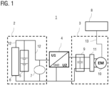
- the electrical system 1 shown is, for example, an electrical system 1 of a commercial vehicle, in particular a bus or truck.
- the on-board electrical system 1 includes a first sub-network (basic on-board electrical system) 2, in which a first mains voltage U1 of 24 volts is present and which includes a first energy storage 5 and a load resistor 6.
- the load resistor 6 is formed by at least one, preferably by several consumers.
- the vehicle electrical system 1 includes a second sub-network 3, in which a second mains voltage U2 of 48 volts is present and in which an electrical machine 10 is provided.
- the electric machine 10 is designed to start an internal combustion engine of the motor vehicle as part of a start-stop operation and for generator operation or recuperation operation and thus represents part of the mild hybrid drive.
- a second energy storage 9 is provided, which is connected to the electrical machine 10 via an inverter 11.
- the second energy storage 9 is designed to store electrical energy generated by the electrical machine 10 in generator operation or recuperation operation.
- the energy storage 9 can only be designed as a double-layer capacitor, for example.
- the first energy storage 5 can also be designed as a capacitor storage or as a lead battery or lithium-ion battery.
- additional consumers can also be arranged in the second subnetwork 3, for which operation with a 48V operating voltage is advantageous, e.g. B. more efficient.
- the power lines 12 are in Figure 1 marked with solid black lines.
- the on-board electrical system 1 further comprises a voltage converter 4, which connects the first sub-network 2 to the second sub-network 3, so that the first sub-network 2 can be supplied with electrical energy from the second sub-network 3.
- the voltage converter 4 is designed to receive a direct voltage from one of the sub-networks 2, 3, for example a direct voltage with which the first sub-network 2 is operated, and to generate an output voltage which is different from the voltage received on the input side (DC/DC converter).
- the voltage converter 4 can also be designed to be bidirectional.
- the on-board electrical system further comprises a control unit 8, which is connected via corresponding signal lines to the corresponding components of the on-board electrical system 1, in particular the voltage converter and the electrical machine 10, with only the signal line 13 to the electrical machine 10 being shown here as a dotted line.
- the signal line or control line 13 is used to control the electrical machine 13, ie, for example, to transmit the voltage specification for the electrical machine 10.
- the control unit 8 can be designed as a separate control device for controlling the electrical machine 10 or as part of a higher-level control unit (not shown), which monitors and controls other components of the vehicle electrical system 1, in particular the voltage converter 4 and the energy storage 5, 9.
- a higher-level control unit receives, for example, from the energy stores 5, 9 and from a battery management system (not shown) of the energy stores 5, 9 data about the charge states of the energy stores 5, 9.
- the control unit is further designed to be connected to the voltage converter 4 depending on the received charge states or to output control signals corresponding to load requirements.
- the voltage converter 4 is set up to transmit energy from the first subnetwork 2 to the second subnetwork 3 and, if necessary, vice versa if it is designed bidirectionally.
- a higher-level vehicle electrical system control unit is known from the prior art and is therefore not described in more detail here.
- Figure 2 shows a schematic flow diagram to illustrate an operating method according to an exemplary embodiment of the invention, which is carried out by the control device 8 of the electrical machine 10.
- a vehicle start i.e. H. current vehicle operating data 21 is determined while the motor vehicle is driving.
- the current power requirement of the vehicle electrical system 1 the current charge status of the second energy storage 9 and the current vehicle speed are determined.
- step S2 It is then determined based on the determined vehicle operating data whether excess energy is present in the second energy storage 9. For this purpose, previous driving data 22 and system properties 23 stored in the vehicle by the control device 8 are determined in step S2. In particular, a length of time of past vehicle stops, the travel times between vehicle stops and an average vehicle deceleration are read out. The values of these parameters are based on a driving history, i.e. H. on previous or past driving data.
- past driving data 22 may have been determined by the motor vehicle itself on the basis of past driving behavior or, alternatively, these data may also have been determined based on past driving of one or more other vehicles and then stored in the motor vehicle or otherwise available have been made available.
- the above-mentioned operating parameters and previous driving data are particularly suitable for making a prediction as to whether there is currently excess electrical energy that would be lost for later use and that could therefore be used for motor operation of the electric machine while driving to increase fuel savings.
- the higher the current power requirement of the vehicle electrical system the less energy is available for the motor operation of the electric machine 10 when driving.
- the higher the current vehicle speed the higher the kinetic energy of the vehicle that can be recuperated in the subsequent recuperation process and the more likely it is that excess energy is present.
- the average vehicle deceleration and the electrical performance of the electric machine 10 can also be used to estimate this recuperation energy.
- step S3 it will be explained merely by way of example how it can be decided during driving operation whether and with what power of the electric machine 10 motor operation of the electric machine 10 can be initiated by the control device 8. This is done in step S3 using an evaluation model, which is explained below.
- a recuperation energy E_rek is estimated for a current operating state of the motor vehicle, whereby the recuperation energy E_rek indicates how much energy could be recuperated if the motor vehicle were braked starting from the current driving state to at least a speed threshold value v_min.
- the speed threshold value v_min indicates the speed limit above which energy can be recuperated in recuperation mode and below which no recuperation operation is possible.
- the recuperation energy E_rek thus estimates how much energy from the kinetic kinetic energy of the motor vehicle can be recuperated on average if the motor vehicle is braked to a standstill and, for example, enters a stop phase of stop-start operation.
- the determined or predicted recuperation energy E_rek is determined depending on the current vehicle speed, the average vehicle deceleration, the current on-board network load and the expected electrical performance of the electric machine during recuperation (including derating), which corresponds to a maximum regenerative performance of the recuperation operation.
- An expected braking duration is estimated from the current vehicle speed and an assumed average vehicle deceleration, which was determined on the basis of previous driving data. Based on the expected braking duration, an assumed recuperation performance then results, e.g. B. assuming a maximum regenerative or electrical performance of the electric machine (e.g.
- the energy that is expected to be recuperable if the vehicle is brought to a standstill can be reliably predicted or estimated based on the current driving state of the vehicle.
- the average vehicle deceleration indicates the average deceleration with which the motor vehicle is decelerated during a recuperation process, which was determined on the basis of previous driving data.
- the minimum energy E_Stopp which is required on average for an engine stop phase of a stop-start operation.
- the minimum energy E_Stopp which is required on average for an engine stop phase of a stop-start operation, is determined as the sum of an engine start energy for the start-stop operation and an energy requirement for an on-board power supply during a stop phase of the stop-start operation become. Furthermore, the energy fed back when the internal combustion engine is stopped can be deducted from this energy.
- the engine start energy indicates how much electrical energy from the energy storage is required for the warm start of the internal combustion engine as part of stop-start operation, with the electric machine serving as a starter motor.
- the energy requirement for the on-board network supply is determined depending on an average vehicle idle time in the stop phase and an average on-board network load. In this way, it can be determined how much electrical energy is needed for the basic functions, e.g. B. engine start and on-board power supply, is necessary during the stop phase.
- the specific recuperation energy and the specific minimum energy it can then be determined in step S4 whether and/or how much energy is available for motor operation of the electric machine while driving. If it is determined that there is enough excess energy available, the electric machine is operated by motor while driving until the next vehicle stop. The power with which the electric machine 10 is operated is adjusted so that at most the determined excess energy is output until the next recuperation phase or vehicle stop is expected.
Landscapes
- Engineering & Computer Science (AREA)
- Transportation (AREA)
- Mechanical Engineering (AREA)
- Chemical & Material Sciences (AREA)
- Combustion & Propulsion (AREA)
- Automation & Control Theory (AREA)
- Life Sciences & Earth Sciences (AREA)
- Sustainable Development (AREA)
- Sustainable Energy (AREA)
- Power Engineering (AREA)
- Electric Propulsion And Braking For Vehicles (AREA)
- Hybrid Electric Vehicles (AREA)
Applications Claiming Priority (2)
| Application Number | Priority Date | Filing Date | Title |
|---|---|---|---|
| DE102016012628.0A DE102016012628A1 (de) | 2016-10-21 | 2016-10-21 | Betriebsverfahren und Vorrichtung zur Steuerung eines motorischen Betriebs einer elektrischen Maschine eines Mild-Hybridantriebs eines Kraftfahrzeugs |
| EP17194310.3A EP3312069B1 (fr) | 2016-10-21 | 2017-10-02 | Procédé de fonctionnement et dispositif de commande d'un fonctionnement motorisé d'une machine électrique d'un entraînement hybride doux d'un véhicule à moteur |
Related Parent Applications (2)
| Application Number | Title | Priority Date | Filing Date |
|---|---|---|---|
| EP17194310.3A Division-Into EP3312069B1 (fr) | 2016-10-21 | 2017-10-02 | Procédé de fonctionnement et dispositif de commande d'un fonctionnement motorisé d'une machine électrique d'un entraînement hybride doux d'un véhicule à moteur |
| EP17194310.3A Division EP3312069B1 (fr) | 2016-10-21 | 2017-10-02 | Procédé de fonctionnement et dispositif de commande d'un fonctionnement motorisé d'une machine électrique d'un entraînement hybride doux d'un véhicule à moteur |
Publications (2)
| Publication Number | Publication Date |
|---|---|
| EP4257439A2 true EP4257439A2 (fr) | 2023-10-11 |
| EP4257439A3 EP4257439A3 (fr) | 2023-12-13 |
Family
ID=60019723
Family Applications (2)
| Application Number | Title | Priority Date | Filing Date |
|---|---|---|---|
| EP23187886.9A Pending EP4257439A3 (fr) | 2016-10-21 | 2017-10-02 | Procédé de fonctionnement et dispositif de commande d'un fonctionnement motorisé d'une machine électrique d'un entraînement hybride doux d'un véhicule à moteur |
| EP17194310.3A Active EP3312069B1 (fr) | 2016-10-21 | 2017-10-02 | Procédé de fonctionnement et dispositif de commande d'un fonctionnement motorisé d'une machine électrique d'un entraînement hybride doux d'un véhicule à moteur |
Family Applications After (1)
| Application Number | Title | Priority Date | Filing Date |
|---|---|---|---|
| EP17194310.3A Active EP3312069B1 (fr) | 2016-10-21 | 2017-10-02 | Procédé de fonctionnement et dispositif de commande d'un fonctionnement motorisé d'une machine électrique d'un entraînement hybride doux d'un véhicule à moteur |
Country Status (2)
| Country | Link |
|---|---|
| EP (2) | EP4257439A3 (fr) |
| DE (1) | DE102016012628A1 (fr) |
Families Citing this family (2)
| Publication number | Priority date | Publication date | Assignee | Title |
|---|---|---|---|---|
| DE102020106320A1 (de) | 2020-03-09 | 2021-09-09 | Zf Cv Systems Global Gmbh | Verfahren zum Betreiben eines elektrischen Antriebssystems eines Anhängefahrzeugs einer Zugfahrzeug-Anhängefahrzeug-Kombination sowie elektrisches Antriebssystem |
| DE102020119554B4 (de) * | 2020-07-24 | 2024-07-04 | Audi Aktiengesellschaft | MHEV Betriebsstrategie für optimierte Fahrdynamik |
Citations (1)
| Publication number | Priority date | Publication date | Assignee | Title |
|---|---|---|---|---|
| DE102013014103A1 (de) | 2013-08-24 | 2015-02-26 | Man Truck & Bus Ag | Bordnetz für ein Kraftfahrzeug und Verfahren zum Betrieb eines Bordnetzes |
Family Cites Families (9)
| Publication number | Priority date | Publication date | Assignee | Title |
|---|---|---|---|---|
| JP3654048B2 (ja) * | 1999-05-20 | 2005-06-02 | 日産自動車株式会社 | ハイブリッド車両の駆動制御装置 |
| DE102008043398A1 (de) * | 2008-11-03 | 2010-05-06 | Robert Bosch Gmbh | Verfahren zum Betreiben eines Generators eines Fahrzeugs |
| WO2011039771A2 (fr) * | 2009-09-15 | 2011-04-07 | Kpit Cummins Infosystems Ltd. | Assistance moteur pour véhicule hybride sur la base d'une autonomie prédite |
| SE535514C2 (sv) * | 2010-07-08 | 2012-09-04 | Scania Cv Ab | Energistyrsystem och metod för ett hybridfordon |
| DE102011082336A1 (de) * | 2011-09-08 | 2013-03-14 | Bayerische Motoren Werke Aktiengesellschaft | Verfahren zum Steuern von Energieverteilungsprozessen in einem Fahrzeug |
| US20130096749A1 (en) * | 2011-10-18 | 2013-04-18 | Fuel Motion Inc. | Method for a vehicle control unit (VCU) for control of the engine in a converted hybrid electric powered vehicle |
| US9090255B2 (en) * | 2012-07-12 | 2015-07-28 | Honda Motor Co., Ltd. | Hybrid vehicle fuel efficiency using inverse reinforcement learning |
| FR3022345A1 (fr) * | 2014-06-13 | 2015-12-18 | Peugeot Citroen Automobiles Sa | Methode de determination de gain de consommation en carburant |
| DE102015202548A1 (de) * | 2015-02-12 | 2016-08-18 | Bayerische Motoren Werke Aktiengesellschaft | Start-Stopp-Automatik in einem Kraftfahrzeug |
-
2016
- 2016-10-21 DE DE102016012628.0A patent/DE102016012628A1/de active Pending
-
2017
- 2017-10-02 EP EP23187886.9A patent/EP4257439A3/fr active Pending
- 2017-10-02 EP EP17194310.3A patent/EP3312069B1/fr active Active
Patent Citations (1)
| Publication number | Priority date | Publication date | Assignee | Title |
|---|---|---|---|---|
| DE102013014103A1 (de) | 2013-08-24 | 2015-02-26 | Man Truck & Bus Ag | Bordnetz für ein Kraftfahrzeug und Verfahren zum Betrieb eines Bordnetzes |
Also Published As
| Publication number | Publication date |
|---|---|
| EP3312069A1 (fr) | 2018-04-25 |
| EP3312069B1 (fr) | 2024-02-28 |
| EP4257439A3 (fr) | 2023-12-13 |
| DE102016012628A1 (de) | 2018-04-26 |
Similar Documents
| Publication | Publication Date | Title |
|---|---|---|
| EP3095658B1 (fr) | Procede et dispositif de commande destines a recuperer de l'energie dans un vehicule hybride | |
| DE102006001201B4 (de) | Verfahren zur Steuerung eines Batterieladungsvorgangs | |
| EP3515741B1 (fr) | Procédé de fonctionnement d'un véhicule hybride | |
| DE102017206011A1 (de) | DC/DC-Wandler, Batterieenergiemanagementsystem und Hybridfahrzeug | |
| DE102015206514A1 (de) | Koordination der Energiereservierung für Hybridfahrzeuge | |
| DE102005046342B4 (de) | Verfahren zur Regelung einer Ausgangsspannung eines Generators | |
| EP3668747B1 (fr) | Procédé permettant de faire fonctionner un système de gestion de batterie, système de gestion de batterie et véhicule automobile | |
| DE10042414A1 (de) | System zum Betreiben von elektrischen Traktionskomponenten | |
| DE102006017921A1 (de) | Verfahren zum Betreiben eines Bordnetzes eines Kraftfahrzeugs und Bordnetz eines Kraftfahrzeugs | |
| EP3186129B1 (fr) | Procédé permettant de faire fonctionner un véhicule | |
| DE102015202518A1 (de) | Energieerzeugungs-Steuervorrichtung und Energieerzeugungs-Steuerverfahren für ein Hybridfahrzeug | |
| EP3312069B1 (fr) | Procédé de fonctionnement et dispositif de commande d'un fonctionnement motorisé d'une machine électrique d'un entraînement hybride doux d'un véhicule à moteur | |
| DE102017222197B4 (de) | Verfahren zum Steuern einer elektrischen Anlage eines elektrisch antreibbaren Kraftfahrzeugs sowie Ladezustandssteuereinrichtung für ein Kraftfahrzeug | |
| DE102019112651A1 (de) | Automatische priorisierung von antriebsstrangvorgängen auf oberflächen mit einem niedrigen reibungskoeffizienten | |
| WO2010004023A2 (fr) | Procédé de détection de l'état de charge d'une batterie de véhicule et commande électronique | |
| EP3038852B1 (fr) | Appareil de commande de gestion énergétique et procede pour determiner une caractéristique d'un accumulateur d'énergie électrochimique | |
| DE102016004360B3 (de) | Verfahren zum Steuern einer Energiespeichereinrichtung eines Mild-Hybrid-Kraftfahrzeugs sowie Ladezustandssteuereinrichtung und Kraftfahrzeug mit einer derartigen Ladezustandssteuereinrichtung | |
| EP3476648A1 (fr) | Réseau de bord pour un véhicule automobile, en particulier un véhicule mild-hybride ou micro-hybride | |
| AT512132B1 (de) | Bordnetzspeisung | |
| DE102016007133B4 (de) | Steuervorrichtung und Verfahren zum Betreiben eines Kraftfahrzeugs mit einem Verbrennungsmotor und mit zumindest zwei elektrischen Startereinheiten für den Verbrennungsmotor | |
| DE102009000981B4 (de) | Energiemanagement-Verfahren eines Kraftfahrzeuges | |
| DE102015216686B4 (de) | Rekuperationssteuerung in einem Bordnetz eines Fahrzeugs | |
| EP3650259B1 (fr) | Procédé de fonctionnement d'un véhicule automobile et véhicule automobile | |
| DE102008024415A1 (de) | Energiemanagementsystem in einem Kraftfahrzeug | |
| DE102016004359B4 (de) | Elektrische Anlage für ein elektrisch antreibbares Kraftfahrzeug, Verfahrenzu deren Steuerung sowie Kraftfahrzeug mit einer elektrischen Anlage |
Legal Events
| Date | Code | Title | Description |
|---|---|---|---|
| PUAI | Public reference made under article 153(3) epc to a published international application that has entered the european phase |
Free format text: ORIGINAL CODE: 0009012 |
|
| STAA | Information on the status of an ep patent application or granted ep patent |
Free format text: STATUS: THE APPLICATION HAS BEEN PUBLISHED |
|
| AC | Divisional application: reference to earlier application |
Ref document number: 3312069 Country of ref document: EP Kind code of ref document: P |
|
| AK | Designated contracting states |
Kind code of ref document: A2 Designated state(s): AL AT BE BG CH CY CZ DE DK EE ES FI FR GB GR HR HU IE IS IT LI LT LU LV MC MK MT NL NO PL PT RO RS SE SI SK SM TR |
|
| REG | Reference to a national code |
Ref country code: DE Ref legal event code: R079 Free format text: PREVIOUS MAIN CLASS: B60W0010300000 Ipc: B60W0020140000 |
|
| PUAL | Search report despatched |
Free format text: ORIGINAL CODE: 0009013 |
|
| AK | Designated contracting states |
Kind code of ref document: A3 Designated state(s): AL AT BE BG CH CY CZ DE DK EE ES FI FR GB GR HR HU IE IS IT LI LT LU LV MC MK MT NL NO PL PT RO RS SE SI SK SM TR |
|
| RIC1 | Information provided on ipc code assigned before grant |
Ipc: B60L 58/20 20190101ALI20231108BHEP Ipc: B60W 50/00 20060101ALI20231108BHEP Ipc: B60W 10/30 20060101ALI20231108BHEP Ipc: B60W 10/24 20060101ALI20231108BHEP Ipc: B60W 10/08 20060101ALI20231108BHEP Ipc: B60W 10/06 20060101ALI20231108BHEP Ipc: B60K 6/485 20071001ALI20231108BHEP Ipc: B60W 20/11 20160101ALI20231108BHEP Ipc: B60W 20/10 20160101ALI20231108BHEP Ipc: B60W 30/18 20120101ALI20231108BHEP Ipc: B60W 20/14 20160101AFI20231108BHEP |
|
| STAA | Information on the status of an ep patent application or granted ep patent |
Free format text: STATUS: REQUEST FOR EXAMINATION WAS MADE |
|
| 17P | Request for examination filed |
Effective date: 20240604 |
|
| RBV | Designated contracting states (corrected) |
Designated state(s): AL AT BE BG CH CY CZ DE DK EE ES FI FR GB GR HR HU IE IS IT LI LT LU LV MC MK MT NL NO PL PT RO RS SE SI SK SM TR |