EP4257239A1 - Multifunktionaler mikrofluidischer testchip - Google Patents
Multifunktionaler mikrofluidischer testchip Download PDFInfo
- Publication number
- EP4257239A1 EP4257239A1 EP21899792.2A EP21899792A EP4257239A1 EP 4257239 A1 EP4257239 A1 EP 4257239A1 EP 21899792 A EP21899792 A EP 21899792A EP 4257239 A1 EP4257239 A1 EP 4257239A1
- Authority
- EP
- European Patent Office
- Prior art keywords
- sample
- chamber
- diluent
- quantitative
- reaction
- Prior art date
- Legal status (The legal status is an assumption and is not a legal conclusion. Google has not performed a legal analysis and makes no representation as to the accuracy of the status listed.)
- Pending
Links
Images

Classifications
-
- B—PERFORMING OPERATIONS; TRANSPORTING
- B01—PHYSICAL OR CHEMICAL PROCESSES OR APPARATUS IN GENERAL
- B01L—CHEMICAL OR PHYSICAL LABORATORY APPARATUS FOR GENERAL USE
- B01L3/00—Containers or dishes for laboratory use, e.g. laboratory glassware; Droppers
- B01L3/50—Containers for the purpose of retaining a material to be analysed, e.g. test tubes
- B01L3/502—Containers for the purpose of retaining a material to be analysed, e.g. test tubes with fluid transport, e.g. in multi-compartment structures
- B01L3/5027—Containers for the purpose of retaining a material to be analysed, e.g. test tubes with fluid transport, e.g. in multi-compartment structures by integrated microfluidic structures, i.e. dimensions of channels and chambers are such that surface tension forces are important, e.g. lab-on-a-chip
- B01L3/502723—Containers for the purpose of retaining a material to be analysed, e.g. test tubes with fluid transport, e.g. in multi-compartment structures by integrated microfluidic structures, i.e. dimensions of channels and chambers are such that surface tension forces are important, e.g. lab-on-a-chip characterised by venting arrangements
-
- B—PERFORMING OPERATIONS; TRANSPORTING
- B01—PHYSICAL OR CHEMICAL PROCESSES OR APPARATUS IN GENERAL
- B01L—CHEMICAL OR PHYSICAL LABORATORY APPARATUS FOR GENERAL USE
- B01L3/00—Containers or dishes for laboratory use, e.g. laboratory glassware; Droppers
- B01L3/50—Containers for the purpose of retaining a material to be analysed, e.g. test tubes
- B01L3/502—Containers for the purpose of retaining a material to be analysed, e.g. test tubes with fluid transport, e.g. in multi-compartment structures
- B01L3/5027—Containers for the purpose of retaining a material to be analysed, e.g. test tubes with fluid transport, e.g. in multi-compartment structures by integrated microfluidic structures, i.e. dimensions of channels and chambers are such that surface tension forces are important, e.g. lab-on-a-chip
-
- B—PERFORMING OPERATIONS; TRANSPORTING
- B01—PHYSICAL OR CHEMICAL PROCESSES OR APPARATUS IN GENERAL
- B01F—MIXING, e.g. DISSOLVING, EMULSIFYING OR DISPERSING
- B01F23/00—Mixing according to the phases to be mixed, e.g. dispersing or emulsifying
- B01F23/40—Mixing liquids with liquids; Emulsifying
- B01F23/45—Mixing liquids with liquids; Emulsifying using flow mixing
- B01F23/451—Mixing liquids with liquids; Emulsifying using flow mixing by injecting one liquid into another
-
- B—PERFORMING OPERATIONS; TRANSPORTING
- B01—PHYSICAL OR CHEMICAL PROCESSES OR APPARATUS IN GENERAL
- B01F—MIXING, e.g. DISSOLVING, EMULSIFYING OR DISPERSING
- B01F23/00—Mixing according to the phases to be mixed, e.g. dispersing or emulsifying
- B01F23/40—Mixing liquids with liquids; Emulsifying
- B01F23/48—Mixing liquids with liquids; Emulsifying characterised by the nature of the liquids
- B01F23/483—Mixing liquids with liquids; Emulsifying characterised by the nature of the liquids using water for diluting a liquid ingredient, obtaining a predetermined concentration or making an aqueous solution of a concentrate
-
- B—PERFORMING OPERATIONS; TRANSPORTING
- B01—PHYSICAL OR CHEMICAL PROCESSES OR APPARATUS IN GENERAL
- B01F—MIXING, e.g. DISSOLVING, EMULSIFYING OR DISPERSING
- B01F33/00—Other mixers; Mixing plants; Combinations of mixers
- B01F33/30—Micromixers
- B01F33/301—Micromixers using specific means for arranging the streams to be mixed, e.g. channel geometries or dispositions
- B01F33/3017—Mixing chamber
-
- B—PERFORMING OPERATIONS; TRANSPORTING
- B01—PHYSICAL OR CHEMICAL PROCESSES OR APPARATUS IN GENERAL
- B01F—MIXING, e.g. DISSOLVING, EMULSIFYING OR DISPERSING
- B01F35/00—Accessories for mixers; Auxiliary operations or auxiliary devices; Parts or details of general application
- B01F35/80—Forming a predetermined ratio of the substances to be mixed
- B01F35/83—Forming a predetermined ratio of the substances to be mixed by controlling the ratio of two or more flows, e.g. using flow sensing or flow controlling devices
-
- B—PERFORMING OPERATIONS; TRANSPORTING
- B01—PHYSICAL OR CHEMICAL PROCESSES OR APPARATUS IN GENERAL
- B01F—MIXING, e.g. DISSOLVING, EMULSIFYING OR DISPERSING
- B01F2101/00—Mixing characterised by the nature of the mixed materials or by the application field
- B01F2101/23—Mixing of laboratory samples e.g. in preparation of analysing or testing properties of materials
-
- B—PERFORMING OPERATIONS; TRANSPORTING
- B01—PHYSICAL OR CHEMICAL PROCESSES OR APPARATUS IN GENERAL
- B01L—CHEMICAL OR PHYSICAL LABORATORY APPARATUS FOR GENERAL USE
- B01L2200/00—Solutions for specific problems relating to chemical or physical laboratory apparatus
- B01L2200/02—Adapting objects or devices to another
- B01L2200/026—Fluid interfacing between devices or objects, e.g. connectors, inlet details
- B01L2200/027—Fluid interfacing between devices or objects, e.g. connectors, inlet details for microfluidic devices
-
- B—PERFORMING OPERATIONS; TRANSPORTING
- B01—PHYSICAL OR CHEMICAL PROCESSES OR APPARATUS IN GENERAL
- B01L—CHEMICAL OR PHYSICAL LABORATORY APPARATUS FOR GENERAL USE
- B01L2200/00—Solutions for specific problems relating to chemical or physical laboratory apparatus
- B01L2200/02—Adapting objects or devices to another
- B01L2200/028—Modular arrangements
-
- B—PERFORMING OPERATIONS; TRANSPORTING
- B01—PHYSICAL OR CHEMICAL PROCESSES OR APPARATUS IN GENERAL
- B01L—CHEMICAL OR PHYSICAL LABORATORY APPARATUS FOR GENERAL USE
- B01L2200/00—Solutions for specific problems relating to chemical or physical laboratory apparatus
- B01L2200/06—Fluid handling related problems
- B01L2200/0605—Metering of fluids
-
- B—PERFORMING OPERATIONS; TRANSPORTING
- B01—PHYSICAL OR CHEMICAL PROCESSES OR APPARATUS IN GENERAL
- B01L—CHEMICAL OR PHYSICAL LABORATORY APPARATUS FOR GENERAL USE
- B01L2200/00—Solutions for specific problems relating to chemical or physical laboratory apparatus
- B01L2200/06—Fluid handling related problems
- B01L2200/0647—Handling flowable solids, e.g. microscopic beads, cells, particles
-
- B—PERFORMING OPERATIONS; TRANSPORTING
- B01—PHYSICAL OR CHEMICAL PROCESSES OR APPARATUS IN GENERAL
- B01L—CHEMICAL OR PHYSICAL LABORATORY APPARATUS FOR GENERAL USE
- B01L2200/00—Solutions for specific problems relating to chemical or physical laboratory apparatus
- B01L2200/06—Fluid handling related problems
- B01L2200/0684—Venting, avoiding backpressure, avoid gas bubbles
-
- B—PERFORMING OPERATIONS; TRANSPORTING
- B01—PHYSICAL OR CHEMICAL PROCESSES OR APPARATUS IN GENERAL
- B01L—CHEMICAL OR PHYSICAL LABORATORY APPARATUS FOR GENERAL USE
- B01L2200/00—Solutions for specific problems relating to chemical or physical laboratory apparatus
- B01L2200/10—Integrating sample preparation and analysis in single entity, e.g. lab-on-a-chip concept
-
- B—PERFORMING OPERATIONS; TRANSPORTING
- B01—PHYSICAL OR CHEMICAL PROCESSES OR APPARATUS IN GENERAL
- B01L—CHEMICAL OR PHYSICAL LABORATORY APPARATUS FOR GENERAL USE
- B01L2200/00—Solutions for specific problems relating to chemical or physical laboratory apparatus
- B01L2200/16—Reagents, handling or storing thereof
-
- B—PERFORMING OPERATIONS; TRANSPORTING
- B01—PHYSICAL OR CHEMICAL PROCESSES OR APPARATUS IN GENERAL
- B01L—CHEMICAL OR PHYSICAL LABORATORY APPARATUS FOR GENERAL USE
- B01L2300/00—Additional constructional details
- B01L2300/08—Geometry, shape and general structure
- B01L2300/0809—Geometry, shape and general structure rectangular shaped
- B01L2300/0816—Cards, e.g. flat sample carriers usually with flow in two horizontal directions
-
- B—PERFORMING OPERATIONS; TRANSPORTING
- B01—PHYSICAL OR CHEMICAL PROCESSES OR APPARATUS IN GENERAL
- B01L—CHEMICAL OR PHYSICAL LABORATORY APPARATUS FOR GENERAL USE
- B01L2300/00—Additional constructional details
- B01L2300/08—Geometry, shape and general structure
- B01L2300/0832—Geometry, shape and general structure cylindrical, tube shaped
-
- B—PERFORMING OPERATIONS; TRANSPORTING
- B01—PHYSICAL OR CHEMICAL PROCESSES OR APPARATUS IN GENERAL
- B01L—CHEMICAL OR PHYSICAL LABORATORY APPARATUS FOR GENERAL USE
- B01L2300/00—Additional constructional details
- B01L2300/08—Geometry, shape and general structure
- B01L2300/0861—Configuration of multiple channels and/or chambers in a single devices
- B01L2300/0864—Configuration of multiple channels and/or chambers in a single devices comprising only one inlet and multiple receiving wells, e.g. for separation, splitting
-
- B—PERFORMING OPERATIONS; TRANSPORTING
- B01—PHYSICAL OR CHEMICAL PROCESSES OR APPARATUS IN GENERAL
- B01L—CHEMICAL OR PHYSICAL LABORATORY APPARATUS FOR GENERAL USE
- B01L2300/00—Additional constructional details
- B01L2300/08—Geometry, shape and general structure
- B01L2300/0861—Configuration of multiple channels and/or chambers in a single devices
- B01L2300/087—Multiple sequential chambers
-
- B—PERFORMING OPERATIONS; TRANSPORTING
- B01—PHYSICAL OR CHEMICAL PROCESSES OR APPARATUS IN GENERAL
- B01L—CHEMICAL OR PHYSICAL LABORATORY APPARATUS FOR GENERAL USE
- B01L2400/00—Moving or stopping fluids
- B01L2400/04—Moving fluids with specific forces or mechanical means
- B01L2400/0403—Moving fluids with specific forces or mechanical means specific forces
- B01L2400/0409—Moving fluids with specific forces or mechanical means specific forces centrifugal forces
Definitions
- the present invention relates to the field of in vitro microfluidic detection, in particular to a multifunctional microfluidic detection chip.
- Microfluidic detection chip technology integrates basic operation units such as sample preparation, reaction, separation, and detection in biological, chemical, and medical analysis processes into a micron-scale chip, and automatically completes the entire analysis process. It has great potential in biology, chemistry, medicine and other fields.
- the microfluidic detection chip technology in the prior art still has some defects in practical applications, such as complex structure, large sample usage, inaccurate detection results, too small volume ratio between diluent quantitative chamber and sample quantitative chamber, and high production costs.
- the centrifugal microfluidic detection chip on the market requires a large amount of blood sample, which is not suitable for clinical blood collection and detection of infants, especially newborns and critically ill patients, and lacks effective quality control functions. Therefore, it is necessary to develop a centrifugal detection chip, which has a simple structure, a small amount of sample injection at a time, can detect multiple indicators in a small volume, has low production cost, is suitable for mass production, and has more accurate detection results, and can perform multi-sample detection through chip assembly.
- the purpose of the present invention is to provide a multifunctional microfluidic detection chip, to overcome the defects of the existing microfluidic detection chip technology, thus the sample consumption can be reduced and the accuracy of the detection results can be further improved.
- the sample quantitative chamber includes a first sample quantitative cavity and a second sample quantitative cavity.
- the reaction chamber includes a plurality of equidistantly distributed reaction cavities.
- the volume of the reaction cavities is the same as that of the sample blank cavity.
- the reaction sample in the sample quantitative chamber and the diluent in the diluent quantitative chamber enter the quantitative mixing chamber through microfluidic channel I and microfluidic channel II respectively and are mixed uniformly, the mixed liquid enters the reaction cavities and the sample blank cavity through microfluidic channel III and microfluidic channel IV successively, the microfluidic channel I, the microfluidic channel II and the microfluidic channel III respectively include an inflection point which is close to the center of the chip body relative to the corresponding liquid outflow chamber.
- Channel of the sample blank cavity is wider than those of the reaction cavities.
- the quantitative mixing chamber and the reaction chamber are respectively communicated with the vent holes.
- the quantitative ratio of the reaction sample to the diluent in the quantitative mixing chamber is less than 1:30.
- the quantitative ratio of the reaction sample to the diluent in the quantitative mixing chamber is 1:50.
- the reaction reagent is lyophilized beads prepared by lyophilization.
- the lyophilized beads have a radius ranging from 0.5 mm to 1 mm.
- the microfluidic channel between the sample quantitative chamber and the sample overflow chamber is provided with a sample vent channel connected to the outside of the chip, and the microfluidic channel between the diluent quantitative chamber and the diluent overflow chamber is provided with a diluent vent channel connected to the outside of the chip.
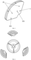
- the chip has a fan-shaped structure.
- the chip further includes a chip upper layer and a chip middle layer, and the chip body is located at lower layer.
- Two sides of the chip body are respectively provided with a splicing slot.
- the chip body is used for detection in biochemical items, immune items, nucleic acid molecule items, and blood coagulation items.
- the present invention has the following advantages:
- the quantitative ratio of the reaction sample and the diluent is designed to be less than 1:30, and an appropriate ratio of the reaction sample and the diluent is selected as required.
- a microfluidic detection chip with a fixed structure is designed. In the application, it is only necessary to change the reagent formula required for different detection indicators, and a chip design template can meet the clinical detection of different items or item combination indicators.
- the multiple reaction cavities have the same three-dimensional size as the sample blank cavity, so the volume is the same, and the volume of the reaction sample and the diluent entered during the reaction are the same. Therefore, only one sample blank cavity is needed to realize effective quality control of the combination of detection indicators of multiple reaction cavities, and at the same time, the chip structure is simplified and the cost is reduced.
- the sample blank cavity is located at the end of the array of reaction cavities, shares a microfluidic channel with the reaction cavity, and can be used as a sample blank cavity and a mixed liquid overflow cavity at the same time.
- the sample blank is the mixed liquid of the reaction sample and the diluent, and the detection result eliminates the influence of the sample itself.
- the detection value of the sample blank can detect whether the amount of the sample and the diluent entering the reaction chamber is sufficient. Therefore, it has the dual functions of improving the accuracy of the detection results and judging the validity of the detection.
- the blood collection volume of the invention is small, only one drop of blood is needed for one sample injection, and simultaneous detection of multiple indicators can be realized, and the blood sample consumption is only 1/10 ⁇ 1/5 of that of common products on the market. Therefore, it is especially suitable for clinical detection of newborns and long-term tumor patients who have difficulty in blood collection due to radiotherapy, chemotherapy and other reasons.
- the chip of the present invention has a fan-shaped structure, and a splicing slot is respectively provided on the left and right edges for splicing two chips. Moreover, three chips can form a circular chip, which can detect three samples at a time, which can greatly increase the throughput of detecting samples.
- the multifunctional microfluidic detection chip of the present invention is made by injection molding, and can be used with detection equipment.
- the detection chip has a fan-shaped structure, preferably a third of the size of a circle, that is, the angle formed by the intersection of the left and right extension lines is 120 degrees.
- the fan-shaped structure can be a part of the circle, and other parts can be designed and added according to the needs.
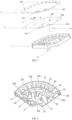
- the multifunctional microfluidic detection chip of the present invention includes upper, middle and lower layers. As shown in FIG. 1 , from top to bottom, there are a chip upper layer 1 serving as a casing, a chip middle layer 2 serving as a sealing layer, and a lower chip serving as a chip body 3.
- the chip upper layer 1 is provided with an upper-layer sample injection chamber through hole 261, an upper-layer diluent storage chamber through hole 262, and a set of upper-layer reaction chamber through holes 263.
- the upper-layer sample injection chamber through hole 261 and the upper-layer diluent storage chamber through hole 262 are located near the center of the chip upper layer 1, and the upper-layer reaction chamber through holes 263 are equally spaced and distributed inside the upper edge of the chip upper layer 1.
- the upper-layer sample injection chamber through hole 261 is used for adding samples, and the upper-layer diluent storage chamber through hole 262 and each of the upper-layer reaction chamber through holes 263 correspond to the diluent storage chamber 12 and each cavity of the reaction chamber, respectively.
- the chip middle layer 2 is provided with a middle-layer sample injection chamber through hole 264, a middle-layer diluent storage chamber through hole 265, a set of vent through holes 266 and a set of positioning hole through holes 267.
- the middle-layer sample injection chamber through hole 264 and the middle-layer diluent storage chamber through hole 265 are located near the center of the chip middle layer 2, corresponding to the upper-layer sample injection chamber through hole 261 and the upper-layer diluent storage chamber through hole 262 in the chip upper layer 1 respectively.
- vent through holes 266 and the positioning hole through holes 267 are sequentially farther from the center of the chip middle layer 2 than the middle-layer sample injection chamber through hole 264 and the middle-layer diluent storage chamber through hole 265; the vent through holes 266 correspond to a set of vent holes I 221 and II 222 on the lower chip body 3, and the positioning hole through holes 267 correspond to a set of positioning holes 25 on the lower chip body 3.
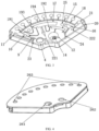
- the chip body 3 is provided with a sample injection chamber 4, a sample quantitative chamber, a sample overflow chamber 11, a diluent storage chamber 12, a diluent quantitative chamber 15, a diluent overflow chamber 16, a quantitative mixing chamber 17, a reaction chamber as well as vent holes I 221 and II 222, and the chambers are connected to each other by microfluidic channels.
- the sample injection chamber 4 and the diluent storage chamber 12 are located near the center of the chip body 3.
- a sample cover 5 is provided on the top of the sample injection chamber 4, and a sample inlet 6 is provided on the sample cover 5 for injecting a sample to be detected.
- the diluent storage chamber 12 is provided with a diluent bag 13 inside and a puncture structure 14 at the bottom, for injecting a diluent.
- the sample quantitative chamber includes a first sample quantitative cavity 9 and a second sample quantitative cavity 10, which are communicated with the sample injection chamber 4. The first sample quantitative cavity 9 and the second sample quantitative cavity 10 are farther from the center of the chip body 3 than the sample injection chamber 4.
- the sample in the sample injection chamber 4 will flow through the bottom port of the sample injection chamber 4 due to centrifugation, through a reverse flow channel, and then through a front flow channel toward the first sample quantitative cavity 9 and the second sample quantitative cavity 10.
- the inlet of the reverse flow channel is located at the bottom of the side of the sample injection chamber 4 close to the first sample quantitative cavity 9, and the outlet of the front flow channel is located on the side of the first sample quantitative cavity 9 close to the center of the chip body 3.
- the reverse flow channel and the front flow channel are connected by a vertical flow channel at the midpoint of the line between the inlet of the reverse flow channel and the outlet of the front flow channel.
- the sample injection chamber 4 is provided with a sample injection chamber flow channel sealing film 8 on the bottom surface to prevent the sample from overflowing when it flows through the reverse flow channel.
- the first sample quantitative cavity 9 and the second sample quantitative cavity 10 are provided to achieve better separation of upper plasma and lower blood cells and quantification of plasma samples.
- the diluent quantitative chamber 15 is communicated with the diluent storage chamber 12, and is farther from the center of the chip body 3 than the diluent storage chamber 12. Therefore, when the chip body 3 is driven to rotate by the centrifugal equipment, the diluent in the diluent storage chamber 12 will flow toward the diluent quantitative chamber 15 because of centrifugation.
- the volume ratio of the first sample quantitative cavity 9 and the second sample quantitative cavity 10 to the diluent quantitative chamber 15 determines the mixing ratio of the reaction sample and the diluent.
- the overflow chamber includes the sample overflow chamber 11 and the diluent overflow chamber 16, which are communicated with the first sample quantitative cavity 9 and the diluent quantitative chamber 15, respectively.
- the sample overflow chamber 11 is farther from the center of the chip body 3 than the first sample quantitative cavity 9 and the second sample quantitative cavity 10. Therefore, when the chip body 3 is driven to rotate by centrifugation, the sample exceeding the capacity of the first sample quantitative cavity 9 and the second sample quantitative cavity 10 will flow into the sample overflow chamber 11 due to the centrifugation.
- the diluent overflow chamber 16 is farther from the center of the chip body 3 than the diluent quantitative chamber 15. Therefore, when the chip body 3 is driven to rotate by centrifugation, the diluent exceeding the capacity of the diluent quantitative chamber 15 will flow into the diluent overflow chamber 16 due to the centrifugation.
- the microfluidic channel between the first sample quantitative cavity 9 and the sample overflow chamber 11 is also connected to the outside of the chip via a sample vent channel 23.
- the microfluidic channel between the diluent quantitative chamber 15 and the diluent overflow chamber 16 is also connected to the outside of the chip via a diluent vent channel 24. Vent channels are provided for smoother flow of diluent and sample.
- the quantitative mixing chamber 17 is communicated with the first sample quantitative cavity 9 and the second sample quantitative cavity 10 through microfluidic channel I 191, and communicated with the diluent quantitative chamber 15 through microfluidic channel II 192, respectively.
- the quantitative mixing chamber 17 is farther from the center of the chip body 3 than the first sample quantitative cavity 9, the second sample quantitative cavity 10 and the diluent quantitative chamber 15, so that the quantitative sample and the quantitative diluent are mixed and diluted for detection.
- the mixed liquid flows from the quantitative mixing chamber 17 to reaction cavities 18 in the reaction chamber through microfluidic channel III 193 and microfluidic channel IV 194 to react with the detection reagents therein.
- the reaction chamber includes a plurality of equidistantly distributed reaction cavities 18 and a sample blank cavity 21 at the end of the flow channel.
- the reaction cavities 18 have the same volume, and are provided with reaction reagents required for the reaction.
- the reaction reagent can be lyophilized beads prepared by lyophilization, and the radius of each lyophilized bead is between 0.5 mm and 1 mm.
- the small volume of the reaction reagent increases the loading capacity of the reaction cavities 18 in a chip of the same size, which effectively improves the detection sensitivity and detection efficiency.
- the use of lyophilized beads for the reaction reagent effectively increases the validity period of the reagent storage.
- the channel of the sample blank cavity 21 is wider than the channels of the reaction cavities 18, thereby providing more storage space for the overflow of the mixed liquid in the chip.
- the sample blank cavity 21 can allow the liquid in the quantitative mixing chamber 17 to enter, to eliminate the influence of different samples on the detection result and to detect whether the amount of reaction sample and diluent entering the reaction cavities 18 is sufficient, so that the detection result is more accurate.
- the sample blank cavity 21 in the multifunctional microfluidic chip of the present invention can also be used as a mixed liquid overflow cavity, so that after the reaction in each reaction cavity 18, the excess mixed liquid can enter the sample blank cavity 21.
- the quantitative mixing chamber 17 and the sample blank cavity 21 are respectively communicated with the vent hole I 221 and the vent hole II 222 through microfluidic channels.
- the vent holes I 221 and II 222 penetrate through the chip body 3 located in the lower layer of the chip.
- the vent hole I 221 and the vent hole II 222 can be seen on the back of the chip body 3, and the arrangement of the vent hole I 221 and the vent hole II 222 makes the liquid flow more smoothly.
- the diluent stored in the diluent storage chamber 12 is encapsulated in the diluent bag 13 in a liquid state, and the bottom surface of the diluent bag 13 is provided with a sealing film, which is made of a pierceable material, such as plastic, aluminum foil or aluminum-plastic composite material, etc.
- the matching detection instrument squeezes the diluent bag 13 through the upper-layer diluent storage chamber through hole 262 in the chip upper layer 1, so that the sealing film on the bottom surface of the diluent bag 13 is in contact with the puncture structure 14, and then the diluent bag 13 is ruptured, and the diluent inside flows out.
- microfluidic channel I 191 The pipe shapes of the aforementioned microfluidic channel I 191, microfluidic channel II 192 and microfluidic channel III 193 are designed according to the experimental requirements in consideration of capillary action and siphon action.
- the inflection point of the microfluidic channel I 191 is closer to the center of the chip body 3 than the sample quantitative chamber; the inflection point of the microfluidic channel II 192 is closer to the center of the chip body 3 than the diluent quantitative chamber 15; and the inflection point of the microfluidic channel III 193 is closer to the center of the chip body 3 than the quantitative mixing chamber 17.
- the capillary action causes the liquid to flow to the inflection point of the microfluidic channel; then centrifugal force is applied, and the liquid flows into the next chamber under the siphon action, which acts as a siphon valve.
- the multifunctional microfluidic chip of the present invention also comprises a set of positioning holes 25 located on the left and right sides of the quantitative mixing chamber 17, which are specifically used to ensure the positional accuracy between the layers of the chip, and the layers of the chip are inserted into one body through the positioning holes 25.
- the multifunctional microfluidic chip of the present invention further comprises splicing slots 20 located on the left and right sides of the upper edge of the chip body 3, which are specifically used for splicing two adjacent chips. And finally, the three fan-shaped chip bodies 3 can be spliced into a circular chip, which further increases the number of detection samples.
- the specific steps of using the multifunctional microfluidic detection chip of the present invention are as follows.
- a whole blood sample enters the sample injection chamber 4 through the upper-layer sample injection chamber through hole 261, and is put into the matching detection instrument.
- the diluent release structure of the detection instrument squeezes the diluent bag 13 through the upper-layer diluent storage chamber through hole 262, so that the sealing film on the bottom surface of the diluent bag 13 is in contact with the puncture structure 14, and then the diluent bag 13 is ruptured, and the diluent flows out. Under the action of centrifugation, blood and diluent flow through different microfluidic channels respectively.
- the blood sample enters the first sample quantitative cavity 9 and the second sample quantitative cavity 10, and excess blood enters the sample overflow chamber 11 through the microfluidic channel.
- the blood sample is centrifuged into an upper layer of plasma and a lower layer of blood cells, and the lower layer of blood cells is mainly deposited in the first sample quantitative cavity 9.
- the diluent enters the diluent quantitative chamber 15 through the microfluidic channel, and the excess diluent in the diluent quantitative chamber 15 enters the diluent overflow chamber 16 through the microfluidic channel.
- the configuration of the vent channels makes the flow of the diluent and blood sample smoother, and the centrifugal action can be set to different rotation speeds and centrifugation directions.
- the plasma and diluent flow to the inflection points of microfluidic channels I 191 and II 192 under capillary action, respectively; centrifugal force is then applied, and the siphon action is used to make the quantitative plasma and diluent enter the quantitative mixing chamber 17.
- the plasma and the diluent are fully mixed in the quantitative mixing chamber 17.
- the centrifugation is stopped, the mixed liquid flows to the inflection point of the microfluidic channel III 193 under capillary action again.
- the reaction cavities 18 each has the same three-dimensional size and volume as the sample blank cavity 21.
- the immobilized reagent formulas inside the reaction cavities 18 are different.
- the sample blank cavity 21 is additionally used as a mixed liquid overflow cavity.
- the arrangement of the vent holes I 221 and II 222 makes the liquid flow smoothly.
- the mixed liquid dissolves the preset immobilized each reaction reagent (lyophilized beads) in each reaction cavity 18 to fully react with it.
- the optical path detection device of the matching detection instrument performs optical detection on each reaction cavity, and calculates the detection result.
- the ratio of the reaction sample to the diluent in the present invention is fixed, and the ratio is designed to be less than 1:30, for example, 1:40, 1:50, etc., which are designed according to practical application needs.
- a microfluidic chip with a fixed structure is designed, and the simultaneous detection of multiple indicators can be realized only by changing the detection reagent formula in each reaction cavity 18.
- the blood collection volume is small, and only 20 ⁇ L (one drop of blood) is needed for a single injection, which can realize the simultaneous detection of multiple indicators.
- the blood sample consumption is only one-tenth to one-fifth of that of common products on the market.
- the difference between the solution in the sample blank cavity 21 and the solution in each reaction cavity 18 is that the former does not contain a reaction reagent. That is to say, the mixed liquid after mixing the reaction sample and the diluent is used as the sample blank, which can greatly improve the reliability of the detection result.
- the multifunctional microfluidic detection chip of the present invention can be used for detection items including biochemical items, immune items, nucleic acid molecule items, and blood coagulation items.
- Specific indicators of biochemical items include total bilirubin, direct bilirubin, total bile acids, total protein, albumin, albumin/globulin, alanine aminotransferase, aspartate aminotransferase, alkaline phosphatase, gamma-glutamyl transpeptidase, potassium, sodium, chloride, calcium, magnesium, phosphorus, iron, carbon dioxide, ammonia, aspartate aminotransferase mitochondrial isoenzyme (ASTm), lactate dehydrogenase (LDH), creatine kinase (CK), alpha-hydroxybutyrate dehydrogenase ( ⁇ -HBD), creatine kinase isoenzyme (CK-MB), blood urea nitrogen (BUN), creatinine (Cr), cystatin C (Cy
- Indicators of immune items include cardiac troponin I, procalcitonin, N-terminal brain natriuretic peptide precursor, thyroid stimulating hormone, total triiodothyronine, free triiodothyronine, total thyroxine, free thyroxine , estradiol, anti-Mullerian hormone, brain natriuretic peptide, cardiac fatty acid-binding protein, interleukin-6, lipoprotein-related phospholipase A2, serum amyloid A, soluble growth-stimulating expression gene 2 protein, creatine kinase isoenzyme CK-NM, myoglobin Myo, luteinizing hormone, follicle-stimulating hormone, prolactin, testosterone, progesterone, 25-hydroxyvitamin D3, 25-hydroxyvitamin D, immunoglobulin G4, cardiac troponin T, myeloperoxidase, aldosterone, renin, homocysteine, D-d
- Indicators of nucleic acid molecule items include Mycoplasma pneumoniae, Chlamydia pneumoniae, Legionella pneumophila, Influenza A virus, Influenza B virus, Bacillus pertussis, Streptococcus pneumoniae, Respiratory syncytial virus, Parainfluenza virus, Rhinovirus, Respiratory adenovirus.
- Indicators of blood coagulation items include prothrombin time (PT), thrombin time (TT), activated partial thromboplastin time (APTT), activated coagulation time (ACT), fibrinogen (FIB), fibrin degradation product (FDP), coagulation factor Xa, Russell-viper-venom time (RVVT), Antithrombin III (AT III), D-dimer.
- PT prothrombin time
- TT thrombin time
- APTT activated partial thromboplastin time
- ACT activated coagulation time
- FIB fibrinogen
- FDP fibrin degradation product
- coagulation factor Xa Russell-viper-venom time
- RVVT Russell-viper-venom time
- AT III Antithrombin III
- each detection reagent was firstly fixed in each reaction cavity 18.
- Lyophilized (freeze-dried) beads were prepared by lyophilization (freeze-drying), and each lyophilized bead had a diameter of 0.5-1.0 mm, and the beads were stored in a dry state at 4-8°C.
- the specific steps were: Frozen beads preparation: the drop volume of automatic bead drop machine (Xiamen Wumen Automation Technology Co., Ltd.; LC200-R) was adjusted to be accurate to 2-100 ⁇ L (preferably 4 ⁇ L) per drop of reagent beads.
- a matching thermal insulation container containing liquid nitrogen was installed, parameters such as the liquid level height were adjusted, and then bead drop was started.
- Each reagent was dropped into liquid nitrogen to quickly form frozen beads and sink to the bottom of the liquid nitrogen container.
- the frozen beads were poured into a freeze-drying container for further vacuum freeze-drying.
- freeze-dried (lyophilized) beads the above frozen beads were placed into a vacuum freeze-drying instrument (Shanghai Tofflon Technology; LYO-0.5). Instrument parameters were set, drying time was 24-28 hours, the frozen beads were dehydrated to form freeze-dried beads, and after completion, they were taken out and placed in a closed container.
- a vacuum freeze-drying instrument Shanghai Tofflon Technology; LYO-0.5. Instrument parameters were set, drying time was 24-28 hours, the frozen beads were dehydrated to form freeze-dried beads, and after completion, they were taken out and placed in a closed container.
- the microfluidic detection chip of the present invention has a fixed structure, and the ratio of reaction sample to diluent is designed to be 1:50. Using the multifunctional microfluidic detection chip of the invention, only 20 ⁇ L of whole blood is needed for one sample injection. The chip is placed in a matching detection instrument. The diluent flows out from the diluent storage chamber 12 and enters the diluent quantitative chamber 15, and the excess diluent enters the diluent overflow chamber 16. The whole blood sample is stratified after centrifugation, the blood cells are mainly deposited in the first sample quantitative cavity 9, and the plasma is in the second sample quantitative cavity 10.
- the detection results of the nine reaction cavities 18 are subtracted from the detection results of the sample blank cavity 21, which eliminates the influence of different samples on the results. It can also be checked whether the amount of the reaction sample and the diluent entering each reaction cavity 18 is sufficient. Therefore, it has the dual functions of improving the accuracy of the detection results and judging the validity of the detection.
- the blood sample consumption of the present invention is only 1/10 ⁇ 1/5 of that of common products on the market, and the blood collection volume is small, and is especially suitable for clinical detection of newborns and long-term tumor patients who have difficulty in blood collection due to radiotherapy, chemotherapy and other reasons.
- the structure of the microfluidic detection chip is fixed, and the ratio of reaction sample and diluent is fixed. Only by changing the reagent formula required for different detection indicators, a single chip design template can be used to realize the clinical detection of different items or item combinations.
- the configuration of the splicing slots 20 can assemble three detection chips into one circular detection chip, and can detect three different samples at the same time, thereby increasing the throughput of detecting samples. 1.
- Sample to Reagent Volume Ratio Product Indicate r 1 (TP) Indicate r2 (ALB) Indicator 3 (TB) Indicate r 4 (DB) Indicate r5 (TBA) Indicate r6 (AST) Indicate r7 (ALT) Indicate r8 (ALP) Indicate r9 (GGT) Product 1 1:100 1:100 1:35 1:35 1:80 1:25 1:25 1:50 1:18.7 Product 2 1:61 1:60 1:75.5 1:21.5 null 1:8.4 1:8.4 1:32.9 1:15 Inventio n 1:50 1:50 1:50 1:50 1:50 1:50 1:
- the invention uses the chip as the carrier to realize the fixation of the sample-to-reagent ratio, and then the structure of the chip is fixed, the three-dimensional size and volume of the reaction pool are the same, and the same amount of sample entering the reaction pool is ensured, and only the reagent formulas for different detection indicators need to be changed. Therefore, the chip structure is fixed, the cost of molding is reduced, and mass production is facilitated. 2.
- the present invention detects nine indicators, and the blood volume of each indicator is roughly calculated to be 2.2 ⁇ L. In fact, only one drop of blood can be used to detect nine indicators, and the blood collection volume is small. It is especially suitable for clinical detection of newborns and long-term tumor patients who have difficulty in blood collection due to radiotherapy, chemotherapy and other reasons.
- the product of the present invention can achieve better performance, and the product detection results are accurate and stable.
Landscapes
- Chemical & Material Sciences (AREA)
- Chemical Kinetics & Catalysis (AREA)
- Health & Medical Sciences (AREA)
- Dispersion Chemistry (AREA)
- Analytical Chemistry (AREA)
- General Health & Medical Sciences (AREA)
- Hematology (AREA)
- Clinical Laboratory Science (AREA)
- Automatic Analysis And Handling Materials Therefor (AREA)
- Investigating Or Analysing Biological Materials (AREA)
Applications Claiming Priority (2)
| Application Number | Priority Date | Filing Date | Title |
|---|---|---|---|
| CN202011375534.4A CN112169853B (zh) | 2020-12-01 | 2020-12-01 | 一种多功能微流控检测芯片 |
| PCT/CN2021/127908 WO2022116758A1 (zh) | 2020-12-01 | 2021-11-01 | 一种多功能微流控检测芯片 |
Publications (2)
| Publication Number | Publication Date |
|---|---|
| EP4257239A1 true EP4257239A1 (de) | 2023-10-11 |
| EP4257239A4 EP4257239A4 (de) | 2024-12-25 |
Family
ID=73918244
Family Applications (1)
| Application Number | Title | Priority Date | Filing Date |
|---|---|---|---|
| EP21899792.2A Pending EP4257239A4 (de) | 2020-12-01 | 2021-11-01 | Multifunktionaler mikrofluidischer testchip |
Country Status (6)
| Country | Link |
|---|---|
| US (1) | US20230249180A1 (de) |
| EP (1) | EP4257239A4 (de) |
| JP (1) | JP2023509368A (de) |
| KR (1) | KR20220113775A (de) |
| CN (1) | CN112169853B (de) |
| WO (1) | WO2022116758A1 (de) |
Cited By (1)
| Publication number | Priority date | Publication date | Assignee | Title |
|---|---|---|---|---|
| CN117483017A (zh) * | 2023-11-02 | 2024-02-02 | 北京亘芯科技有限公司 | 一种全封闭式生物检测微流控芯片及其应用方法 |
Families Citing this family (34)
| Publication number | Priority date | Publication date | Assignee | Title |
|---|---|---|---|---|
| CN112169853B (zh) * | 2020-12-01 | 2021-02-26 | 南京岚煜生物科技有限公司 | 一种多功能微流控检测芯片 |
| CN114849797A (zh) * | 2021-01-20 | 2022-08-05 | 南京岚煜生物科技有限公司 | 一种基于相变材料封闭试剂的微流控芯片 |
| CN113634295B (zh) * | 2021-09-14 | 2022-11-04 | 南京岚煜生物科技有限公司 | 一种微流控血型检测芯片 |
| CN216285330U (zh) * | 2021-10-27 | 2022-04-12 | 苏州含光微纳科技有限公司 | 一种生化项目检测装置 |
| CN113877645A (zh) * | 2021-10-29 | 2022-01-04 | 深圳迈瑞动物医疗科技有限公司 | 微流控芯片 |
| CN114113642A (zh) * | 2021-11-15 | 2022-03-01 | 成都微康生物科技有限公司 | 一种使用微流控技术进行凝血分析的检测试剂盒及方法 |
| CN114247489B (zh) * | 2021-12-10 | 2022-08-26 | 广州国家实验室 | 微流控芯片及外泌体提取方法 |
| CN114433259B (zh) * | 2021-12-24 | 2023-12-26 | 广州万孚生物技术股份有限公司 | 均相测试微流控芯片及检测系统 |
| CN114414823B (zh) * | 2022-02-24 | 2025-10-14 | 含光微纳科技(太仓)有限公司 | 一种生化项目检测盘片 |
| CN114558629B (zh) * | 2022-03-03 | 2024-06-04 | 四川微康朴澜医疗科技有限责任公司 | 一种微流控式血栓弹力分析检测试剂盒 |
| CN115193358B (zh) * | 2022-07-21 | 2024-05-28 | 扬州大学 | 一种试管形多功能微流控反应装置 |
| CN115055287B (zh) * | 2022-08-12 | 2022-11-04 | 普迈德(北京)科技有限公司 | 一种离心式微流控芯片、送盘装置以及血浆分离取样方法 |
| CN115254220B (zh) * | 2022-09-27 | 2022-12-16 | 深圳市卓润生物科技有限公司 | 微流控芯片及检测方法 |
| CN115591593B (zh) * | 2022-10-09 | 2025-05-16 | 深圳市卓润生物科技有限公司 | 检测过敏原的微流控芯片及方法 |
| CN115791763B (zh) * | 2022-10-20 | 2023-11-14 | 胜泰生科(广州)医疗科技有限公司 | 均相发光检测装置及应用 |
| WO2024082229A1 (zh) * | 2022-10-20 | 2024-04-25 | 深圳迈瑞动物医疗科技股份有限公司 | 微流控芯片及微流控分析系统 |
| EP4675249A1 (de) * | 2023-02-27 | 2026-01-07 | Phc Holdings Corporation | Trennbehälter für biologische proben, trennsteuerungsvorrichtung für biologische proben, trennsteuerungsverfahren für biologische proben und trennsteuerungsprogramm für biologische proben |
| CN116380881B (zh) * | 2023-03-02 | 2024-07-05 | 厦门宝太和瑞生物技术有限公司 | 用于光激化学检测的试剂容置盒、试剂盒及其使用方法 |
| CN116773829A (zh) * | 2023-03-03 | 2023-09-19 | 杭州安旭生物科技股份有限公司 | 凝血检测盘片、凝血检测组件及其使用方法 |
| CN116196991B (zh) * | 2023-04-11 | 2024-01-19 | 江苏泽亚生物技术有限公司 | 一种微流控血型抗原鉴定芯片 |
| CN116840216A (zh) * | 2023-05-06 | 2023-10-03 | 斯马特诊断技术(成都)有限公司 | 一种微流控化学发光试剂盘使用方法 |
| CN116519871B (zh) * | 2023-05-06 | 2024-01-26 | 西南大学 | 一种基于定量虹吸阀的离心式微量滴定芯片及滴定方法 |
| CN119237033B (zh) * | 2023-07-03 | 2026-02-17 | 北京博奥晶典生物技术有限公司 | 生物反应芯片、生物反应设备及生物检测方法 |
| CN116735572B (zh) * | 2023-07-10 | 2026-02-24 | 广州聚焦生物科技有限公司 | 一种微流控发光检测试剂盘及发光检测方法 |
| CN116794020B (zh) * | 2023-07-10 | 2026-04-17 | 广州聚焦生物科技有限公司 | 一种微流控发光检测装置、方法、电子设备及存储介质 |
| CN118751418A (zh) * | 2023-10-30 | 2024-10-11 | 浙江普施康生物科技有限公司 | 离心式液体多段分离装置及其运作方法 |
| CN117531554B (zh) * | 2023-11-10 | 2026-04-21 | 成都斯马特科技股份有限公司 | 一种微流控扇形生化试剂盘组件及其使用方法 |
| CN117233412B (zh) * | 2023-11-13 | 2024-02-02 | 成都斯马特科技有限公司 | 微流控生化试剂盘及生化检验分析方法 |
| CN117696136B (zh) * | 2023-12-01 | 2024-08-06 | 苏州思迈德生物科技有限公司 | 一种微流控芯片及进液控制方法 |
| CN119406463A (zh) * | 2024-10-18 | 2025-02-11 | 杭州索唯技术有限公司 | 一种用于献血初筛微流控芯片 |
| CN119076074B (zh) * | 2024-11-06 | 2025-02-18 | 北京泰豪生物科技有限公司 | 一种用于试剂精准定量的微流控芯片 |
| CN119500298B (zh) * | 2024-11-20 | 2025-10-14 | 湘潭大学 | 微流控血浆分离系统和方法、血液中生物标志物的检测系统 |
| CN119464039A (zh) * | 2024-11-22 | 2025-02-18 | 北京清华长庚医院 | 用于膝关节运动损伤基因检测的离心微流控芯片 |
| CN119771623B (zh) * | 2024-12-31 | 2026-01-30 | 中国科学院重庆绿色智能技术研究院 | 基于离心微流控无堵塞多级微塑料颗粒分级分选装置及检测方法 |
Family Cites Families (30)
| Publication number | Priority date | Publication date | Assignee | Title |
|---|---|---|---|---|
| CA2192196C (en) * | 1994-06-06 | 2004-11-23 | Anne R. Kopf-Sill | Modified siphons for improved metering precision |
| KR20020021810A (ko) * | 1999-08-11 | 2002-03-22 | 야마모토 카즈모토 | 분석용 카트리지 및 송액 제어 장치 |
| US7122153B2 (en) * | 2003-01-08 | 2006-10-17 | Ho Winston Z | Self-contained microfluidic biochip and apparatus |
| US20080257754A1 (en) * | 2003-06-27 | 2008-10-23 | Pugia Michael J | Method and apparatus for entry of specimens into a microfluidic device |
| JP2005345160A (ja) * | 2004-05-31 | 2005-12-15 | Advance Co Ltd | 生体情報分析ユニット |
| JP4011071B2 (ja) * | 2005-03-25 | 2007-11-21 | 中央電子株式会社 | 嚥下音解析システム |
| US8168444B2 (en) * | 2007-04-09 | 2012-05-01 | Panasonic Corporation | Substrate having channel portion including chambers, and method of transferring liquid by using the substrate |
| EP2017006A1 (de) * | 2007-07-20 | 2009-01-21 | Koninklijke Philips Electronics N.V. | Mikrofluidische Verfahren und Systeme zur Verwendung bei der Analytdetektion |
| NZ582786A (en) * | 2007-07-23 | 2012-09-28 | Clondiag Gmbh | Assays for nucleic acids |
| KR101335727B1 (ko) * | 2007-08-22 | 2013-12-04 | 삼성전자주식회사 | 원심력 기반의 혈액 검사용 디스크형 미세유동장치 |
| JP2011021955A (ja) * | 2009-07-15 | 2011-02-03 | Panasonic Corp | 分析用デバイスと分析方法 |
| JP5489846B2 (ja) * | 2010-04-30 | 2014-05-14 | 三栄源エフ・エフ・アイ株式会社 | 易嚥下性組成物の評価または選別方法 |
| ES2653916T3 (es) * | 2011-03-08 | 2018-02-09 | Universite Laval | Dispositivo centrípeto fluídico |
| JP5952536B2 (ja) * | 2011-07-12 | 2016-07-13 | 国立大学法人 筑波大学 | 嚥下機能データ測定装置及び嚥下機能データ測定システム及び嚥下機能データ測定方法 |
| AU2012350134B2 (en) * | 2011-12-07 | 2015-06-11 | Royal Melbourne Institute Of Technology | Centrifugal microfluidic device |
| KR101702275B1 (ko) * | 2013-08-26 | 2017-02-03 | 가꼬우호우징 효고 이카다이가쿠 | 연하 추정 장치, 정보 단말 장치 및 프로그램 |
| CN105460888A (zh) * | 2015-11-19 | 2016-04-06 | 博奥生物集团有限公司 | 一种芯片的封装方法 |
| CN205176030U (zh) * | 2015-12-09 | 2016-04-20 | 博奥生物集团有限公司 | 全集成血液生化检测芯片 |
| CN206229378U (zh) * | 2016-08-24 | 2017-06-09 | 杭州霆科生物科技有限公司 | 一种离心式尿常规检测微流控芯片 |
| CN107677838A (zh) * | 2017-08-10 | 2018-02-09 | 深圳市金大精密制造有限公司 | 检测集成芯片及其检测方法 |
| JP2019093377A (ja) * | 2017-11-22 | 2019-06-20 | 株式会社エンプラス | 流体チップ、流体デバイスおよびそれらの製造方法 |
| GB201806931D0 (en) * | 2018-04-27 | 2018-06-13 | Radisens Diagnostics Ltd | An improved point-of-care diagnostic assay cartridge |
| CN108855264A (zh) * | 2018-07-12 | 2018-11-23 | 北京乐普智慧医疗科技有限公司 | 一种多用途多指标微流控芯片 |
| CN109999931B (zh) * | 2019-04-18 | 2023-08-11 | 天津诺迈科技有限公司 | 化学发光检测用微流控芯片及使用方法、试剂清洗方法 |
| CN210347665U (zh) * | 2019-04-30 | 2020-04-17 | 杭州艾替捷英科技有限公司 | 非洲猪瘟病毒微流控检测仪 |
| CN110058007B (zh) * | 2019-05-12 | 2024-10-18 | 南京岚煜生物科技有限公司 | 单通道微流控芯片 |
| CN210626498U (zh) * | 2019-09-30 | 2020-05-26 | 中国人民解放军陆军军医大学第二附属医院 | 适用于快速检测的生化组合试剂盘 |
| CN211216727U (zh) * | 2019-11-09 | 2020-08-11 | 深圳市宝安区人民医院 | 一种检测心衰指标的微流控芯片 |
| CN111218395B (zh) * | 2020-04-18 | 2020-08-07 | 博奥生物集团有限公司 | 一种全流程生物检测装置 |
| CN112169853B (zh) * | 2020-12-01 | 2021-02-26 | 南京岚煜生物科技有限公司 | 一种多功能微流控检测芯片 |
-
2020
- 2020-12-01 CN CN202011375534.4A patent/CN112169853B/zh active Active
-
2021
- 2021-11-01 US US18/012,653 patent/US20230249180A1/en active Pending
- 2021-11-01 JP JP2022537199A patent/JP2023509368A/ja active Pending
- 2021-11-01 EP EP21899792.2A patent/EP4257239A4/de active Pending
- 2021-11-01 KR KR1020227023687A patent/KR20220113775A/ko active Pending
- 2021-11-01 WO PCT/CN2021/127908 patent/WO2022116758A1/zh not_active Ceased
Cited By (1)
| Publication number | Priority date | Publication date | Assignee | Title |
|---|---|---|---|---|
| CN117483017A (zh) * | 2023-11-02 | 2024-02-02 | 北京亘芯科技有限公司 | 一种全封闭式生物检测微流控芯片及其应用方法 |
Also Published As
| Publication number | Publication date |
|---|---|
| KR20220113775A (ko) | 2022-08-16 |
| US20230249180A1 (en) | 2023-08-10 |
| JP2023509368A (ja) | 2023-03-08 |
| CN112169853B (zh) | 2021-02-26 |
| CN112169853A (zh) | 2021-01-05 |
| WO2022116758A1 (zh) | 2022-06-09 |
| EP4257239A4 (de) | 2024-12-25 |
Similar Documents
| Publication | Publication Date | Title |
|---|---|---|
| EP4257239A1 (de) | Multifunktionaler mikrofluidischer testchip | |
| EP4174494B1 (de) | Mikrofluidischer testchip vom bluttyp | |
| US9182384B2 (en) | Analyzing device and analyzing method using same | |
| Cunningham | Fluidics and sample handling in clinical chemical analysis | |
| EP2209008B1 (de) | Analysevorrichtung sowie analysegerät und -verfahren unter verwendung davon | |
| US4121905A (en) | Process for preparing biological compositions for use as reference controls in diagnostic analyses | |
| US12083513B2 (en) | Specimen acceptance devices and attachable disposable assay cartridges | |
| US8481301B2 (en) | Centrifugal micro-fluidic structure for measuring glycated hemoglobin, centrifugal micro-fluidic device for measuring glycated hemoglobin, and method for measuring glycated hemoglobin | |
| CN114849797A (zh) | 一种基于相变材料封闭试剂的微流控芯片 | |
| EP2133149A1 (de) | Lab-on-Disc-Vorrichtung | |
| CN112577902A (zh) | 一种用于糖化白蛋白检测的离心式微流控芯片及使用方法 | |
| CN115055287A (zh) | 一种离心式微流控芯片、送盘装置以及血浆分离取样方法 | |
| CN114433259B (zh) | 均相测试微流控芯片及检测系统 | |
| CN108387564B (zh) | 基于微流控芯片的降钙素原检测试剂盒及制备和检测方法 | |
| WO2009061054A1 (en) | Reagent vessel | |
| CN116196991B (zh) | 一种微流控血型抗原鉴定芯片 | |
| CN118122400A (zh) | 一种离心式干式生化检测微流控芯片及其使用方法 | |
| CN219209993U (zh) | 微流控芯片 | |
| US20140377851A1 (en) | Analysis device | |
| CN118226048A (zh) | 微流控分析仪及微流控检测方法 | |
| CN119998662A (zh) | 微流控芯片及微流控分析系统 | |
| CN214794404U (zh) | 一种用于糖化白蛋白检测的离心式微流控芯片 | |
| CN221720822U (zh) | 一种同时进行分子诊断、免疫诊断、生化检测的微流控芯片 | |
| CN111198268B (zh) | 一种生物流体样本检测试剂盒及其检测系统与应用 | |
| TW202508710A (zh) | 卡匣及其定量方法 |
Legal Events
| Date | Code | Title | Description |
|---|---|---|---|
| STAA | Information on the status of an ep patent application or granted ep patent |
Free format text: STATUS: THE INTERNATIONAL PUBLICATION HAS BEEN MADE |
|
| PUAI | Public reference made under article 153(3) epc to a published international application that has entered the european phase |
Free format text: ORIGINAL CODE: 0009012 |
|
| STAA | Information on the status of an ep patent application or granted ep patent |
Free format text: STATUS: REQUEST FOR EXAMINATION WAS MADE |
|
| 17P | Request for examination filed |
Effective date: 20221215 |
|
| AK | Designated contracting states |
Kind code of ref document: A1 Designated state(s): AL AT BE BG CH CY CZ DE DK EE ES FI FR GB GR HR HU IE IS IT LI LT LU LV MC MK MT NL NO PL PT RO RS SE SI SK SM TR |
|
| DAV | Request for validation of the european patent (deleted) | ||
| DAX | Request for extension of the european patent (deleted) | ||
| A4 | Supplementary search report drawn up and despatched |
Effective date: 20241125 |
|
| RIC1 | Information provided on ipc code assigned before grant |
Ipc: B01L 3/00 20060101AFI20241119BHEP |
|
| STAA | Information on the status of an ep patent application or granted ep patent |
Free format text: STATUS: EXAMINATION IS IN PROGRESS |
|
| 17Q | First examination report despatched |
Effective date: 20250812 |
|
| STAA | Information on the status of an ep patent application or granted ep patent |
Free format text: STATUS: THE APPLICATION IS DEEMED TO BE WITHDRAWN |