EP4256637B1 - Herstellungsverfahren für elektrodenanordnung - Google Patents
Herstellungsverfahren für elektrodenanordnung Download PDFInfo
- Publication number
- EP4256637B1 EP4256637B1 EP22838066.3A EP22838066A EP4256637B1 EP 4256637 B1 EP4256637 B1 EP 4256637B1 EP 22838066 A EP22838066 A EP 22838066A EP 4256637 B1 EP4256637 B1 EP 4256637B1
- Authority
- EP
- European Patent Office
- Prior art keywords
- electrode
- stack
- separator
- electrode stack
- electrodes
- Prior art date
- Legal status (The legal status is an assumption and is not a legal conclusion. Google has not performed a legal analysis and makes no representation as to the accuracy of the status listed.)
- Active
Links
Images


Classifications
-
- H—ELECTRICITY
- H01—ELECTRIC ELEMENTS
- H01M—PROCESSES OR MEANS, e.g. BATTERIES, FOR THE DIRECT CONVERSION OF CHEMICAL ENERGY INTO ELECTRICAL ENERGY
- H01M10/00—Secondary cells; Manufacture thereof
- H01M10/04—Construction or manufacture in general
- H01M10/0459—Cells or batteries with folded separator between plate-like electrodes
-
- H—ELECTRICITY
- H01—ELECTRIC ELEMENTS
- H01M—PROCESSES OR MEANS, e.g. BATTERIES, FOR THE DIRECT CONVERSION OF CHEMICAL ENERGY INTO ELECTRICAL ENERGY
- H01M10/00—Secondary cells; Manufacture thereof
- H01M10/04—Construction or manufacture in general
- H01M10/0404—Machines for assembling batteries
-
- H—ELECTRICITY
- H01—ELECTRIC ELEMENTS
- H01M—PROCESSES OR MEANS, e.g. BATTERIES, FOR THE DIRECT CONVERSION OF CHEMICAL ENERGY INTO ELECTRICAL ENERGY
- H01M10/00—Secondary cells; Manufacture thereof
- H01M10/05—Accumulators with non-aqueous electrolyte
- H01M10/052—Li-accumulators
-
- H—ELECTRICITY
- H01—ELECTRIC ELEMENTS
- H01M—PROCESSES OR MEANS, e.g. BATTERIES, FOR THE DIRECT CONVERSION OF CHEMICAL ENERGY INTO ELECTRICAL ENERGY
- H01M10/00—Secondary cells; Manufacture thereof
- H01M10/05—Accumulators with non-aqueous electrolyte
- H01M10/058—Construction or manufacture
- H01M10/0583—Construction or manufacture of accumulators with folded construction elements except wound ones, i.e. folded positive or negative electrodes or separators, e.g. with "Z"-shaped electrodes or separators
-
- H—ELECTRICITY
- H01—ELECTRIC ELEMENTS
- H01M—PROCESSES OR MEANS, e.g. BATTERIES, FOR THE DIRECT CONVERSION OF CHEMICAL ENERGY INTO ELECTRICAL ENERGY
- H01M50/00—Constructional details or processes of manufacture of the non-active parts of electrochemical cells other than fuel cells, e.g. hybrid cells
- H01M50/40—Separators; Membranes; Diaphragms; Spacing elements inside cells
- H01M50/46—Separators, membranes or diaphragms characterised by their combination with electrodes
-
- H—ELECTRICITY
- H01—ELECTRIC ELEMENTS
- H01M—PROCESSES OR MEANS, e.g. BATTERIES, FOR THE DIRECT CONVERSION OF CHEMICAL ENERGY INTO ELECTRICAL ENERGY
- H01M50/00—Constructional details or processes of manufacture of the non-active parts of electrochemical cells other than fuel cells, e.g. hybrid cells
- H01M50/40—Separators; Membranes; Diaphragms; Spacing elements inside cells
- H01M50/463—Separators, membranes or diaphragms characterised by their shape
- H01M50/466—U-shaped, bag-shaped or folded
-
- H—ELECTRICITY
- H01—ELECTRIC ELEMENTS
- H01M—PROCESSES OR MEANS, e.g. BATTERIES, FOR THE DIRECT CONVERSION OF CHEMICAL ENERGY INTO ELECTRICAL ENERGY
- H01M50/00—Constructional details or processes of manufacture of the non-active parts of electrochemical cells other than fuel cells, e.g. hybrid cells
- H01M50/40—Separators; Membranes; Diaphragms; Spacing elements inside cells
- H01M50/489—Separators, membranes, diaphragms or spacing elements inside the cells, characterised by their physical properties, e.g. swelling degree, hydrophilicity or shut down properties
-
- Y—GENERAL TAGGING OF NEW TECHNOLOGICAL DEVELOPMENTS; GENERAL TAGGING OF CROSS-SECTIONAL TECHNOLOGIES SPANNING OVER SEVERAL SECTIONS OF THE IPC; TECHNICAL SUBJECTS COVERED BY FORMER USPC CROSS-REFERENCE ART COLLECTIONS [XRACs] AND DIGESTS
- Y02—TECHNOLOGIES OR APPLICATIONS FOR MITIGATION OR ADAPTATION AGAINST CLIMATE CHANGE
- Y02E—REDUCTION OF GREENHOUSE GAS [GHG] EMISSIONS, RELATED TO ENERGY GENERATION, TRANSMISSION OR DISTRIBUTION
- Y02E60/00—Enabling technologies; Technologies with a potential or indirect contribution to GHG emissions mitigation
- Y02E60/10—Energy storage using batteries
-
- Y—GENERAL TAGGING OF NEW TECHNOLOGICAL DEVELOPMENTS; GENERAL TAGGING OF CROSS-SECTIONAL TECHNOLOGIES SPANNING OVER SEVERAL SECTIONS OF THE IPC; TECHNICAL SUBJECTS COVERED BY FORMER USPC CROSS-REFERENCE ART COLLECTIONS [XRACs] AND DIGESTS
- Y02—TECHNOLOGIES OR APPLICATIONS FOR MITIGATION OR ADAPTATION AGAINST CLIMATE CHANGE
- Y02P—CLIMATE CHANGE MITIGATION TECHNOLOGIES IN THE PRODUCTION OR PROCESSING OF GOODS
- Y02P70/00—Climate change mitigation technologies in the production process for final industrial or consumer products
- Y02P70/50—Manufacturing or production processes characterised by the final manufactured product
Definitions
- Secondary batteries unlike primary batteries, are rechargeable, and have been widely researched and developed in recent years due to their small size and large capacity. As technology development and demand for mobile devices increase, the demand for secondary batteries as an energy source is rapidly increasing.
- Korean Patent Application Laid-Open No. 10-2013-0132230 KR 2020 0023853 A discloses a method of manufacturing an electrode assembly according to the preamble of claim 1.
- the present invention provides, among other things, an electrode assembly manufacturing method that prevents cell damage and deformation of mechanical parts in the process of manufacturing the electrode assembly, involving the stacking of electrodes with a separator.
- the present invention also provides an electrode assembly manufacturing method capable of preventing electrodes from being distorted during the manufacturing process.
- the present invention provides a method of manufacturing an electrode assembly as recited in claim 1.
- the primary heat press operation may include engaging the electrode stack with a gripper to secure a position of the electrode stack, where the application of heat and pressure to the electrode stack during the primary heat press operation occurs while the gripper is engaged with the electrode stack.
- the method may include disengaging the gripper from the electrode stack before performing the pre-heating operation.
- the separator portions may be portions of an elongated separator sheet.
- the step of assembling the electrode stack may include alternately stacking a first one of the electrodes and a second one of the electrodes on the elongated separator sheet.
- the elongated separator sheet may be sequentially folded over a previously-stacked one of the first and second electrodes before a subsequent one of the first and second electrode is stacked.
- the electrodes may be bonded to the separator without the need to individually heat and/or press each level of the electrode assembly (i.e., heating and/or pressing each electrode and separator pair at each step of the process). heating and stacking the electrode and the separator.
- it is beneficially possible to avoid the detrimental accumulation of heat and/or pressure in the lower separators in the stack, and thereby reduce the likelihood of damage and deformation of the components of the electrode assembly.
- the heating and pressing the stack desirably occur under low temperature and low pressure conditions during at least some of the steps of the process.
- the inventive method may beneficially reduce deviations in: adhesive force between the electrodes and the separator, air permeability of the separator, and thickness of the manufactured electrode assembly, thereby resulting in increased uniformity.
- the invention also desirably reduces any distortion or shifting of the positions of the electrodes in the electrode stack. Beneficially, that may result in reduced manufacturing time, as well as improved energy density of the manufactured electrode assembly.
- An exemplary embodiment of the present invention provides an electrode assembly manufacturing method.
- the method may include: supplying a first electrode to a stack table; supplying a second electrode to the stack table; supplying a separator to the stack table; and assembling a stack on the stack table by alternately stacking the first electrode and the second electrode on the separator, where the separator is sequentially folded over a previously-stacked one of the first and second electrodes before a subsequent one of the first and second electrodes is stacked.
- the method may include performing a primary heat press operation comprising gripping the stack with a gripper and then heating and pressing the stack.
- the "primary heat press” is defined as an operation of heating and pressing the stack before the operation of pre-heating the stack.
- the "secondary heat press” is defined as an operation of heating and pressing the pre-heated stack.
- FIG. 1 is a diagram schematically illustrating a method of manufacturing an electrode assembly according to an exemplary embodiment of the present invention. That is, referring to FIG. 1 , the method may first include a stack process of assembling a stack (stack cell) on a stack table by alternately stacking the first electrode and the second electrode on the separator, where the separator is sequentially folded over a previously-stacked one of the first and second electrodes before a subsequent one of the first and second electrodes is stacked. After the stack process, the stack may be moved away from the stack table. During such time, the separator is pulled, and, after the separator is pulled for a predetermined length, the separator is cut.
- stack process of assembling a stack (stack cell) on a stack table by alternately stacking the first electrode and the second electrode on the separator, where the separator is sequentially folded over a previously-stacked one of the first and second electrodes before a subsequent one of the first and second electrodes is stacked.
- the stack may be moved away
- the predetermined length of the cut end of the separator is wound around the stack cell.
- the movement of the stack away from the stack table may be accomplished by the gripper, which is desirably a moveable component that can grip the stack on the stack table and then move the stack to the press unit, where the heat press operations are performed.
- the primary heat press operation is then performed in a state in which the wound stack cell is gripped with the gripper.
- the grip of the stack cell by the gripper is released, and then the pre-heating operation is performed.
- the secondary heat press operation is performed. When the secondary heat press operation is completed, the finished electrode assembly may be complete.
- the primary heat press operation may include: heating the stack table and/or a pair of pressing blocks; and pressing the stack between the pair of heated pressing blocks, or between a pressing block and the stack table (either or both of which may be heated).
- the primary heat press operation may further include fixing the stack by pressing an upper surface of the stack with the gripper. Such step of fixing the stack may occur prior to or concurrently with the step of heating the stack table and/or the pair of pressing blocks.
- the primary heat press operation may include heating and pressing the stack for a time period from 5 seconds to 20 seconds under a temperature condition from 45°C to 75°C and under a pressure condition from 1 Mpa to 2.5 Mpa.
- the primary heat press operation may include heating and pressing the stack for a time period from 10 seconds to 20 seconds under a temperature condition from 45°C to 65°C and under a pressure condition from 1 Mpa to 2 Mpa.
- the primary heat press operation may include heating and pressing the stack for a time period from 10 seconds to 20 seconds under a temperature condition from 45°C to 60°C and under a pressure condition from 1 Mpa to 1.5 Mpa.
- the secondary heat press operation may include: ceasing the heating of the stack table and/or the pair of pressing blocks; ceasing the pressing of the stack; moving the gripper away from the stack; heating the stack table and/or the pair of pressing blocks to transfer heat to the stack; and pressing the stack between the pair of pressing blocks, or pressing the stack between a pressing block and the stack table (either or both of which may be heated).
- the temperature condition of the secondary heat press operation may be 50°C or more, preferably 55°C or more.
- the temperature condition of the secondary heat press operation may be 85°C or less.
- the temperature condition of the secondary heat press operation may be from 50°C to 85°C, preferably from 55°C to 85°C.
- the pressure condition of the secondary heat press operation may be 1 Mpa or less, and preferably 1.5 Mpa or less.
- the pressure condition of the secondary heat press operation may be 2.5 Mpa or less, and preferably 2 Mpa or less.
- the pressure condition of the secondary heat press operation may be from 1 Mpa to 2.5 Mpa, preferably from 1.5 Mpa to 2.5 Mpa, and more preferably from 1.5 Mpa to 2 Mpa.
- the heating and pressing of the secondary heat press operation may be performed for 10 seconds or less, preferably 9 seconds or less, more preferably 8 seconds or less.
- the heating and pressing of the secondary heat press operation may be performed from 5 seconds to 10 seconds, preferably from 5 seconds to 9 seconds, more preferably from 5 seconds to 8 seconds.
- the secondary heat press operation may involve an operation of heating and pressing the stack for 5 seconds to 10 seconds under a temperature condition of 50°C to 85°C and a pressure condition of 1 Mpa to 2.5 Mpa, preferably, for 5 seconds to 10 seconds under a temperature condition of 55°C to 85°C and a pressure condition of 1.5 Mpa or more and 2.5 Mpa or less. More preferably, the secondary heat press operation may involve an operation of heating and pressing the stack for 5 seconds to 10 seconds under a temperature condition from 50°C to 85°C and a pressure condition from 1.5 Mpa to 2
- the pre-heating is performed between the primary heat press operation and the secondary heat press operation.
- a pressure applied in the operation of pre-heating the stack is lower than pressures applied in the primary heat press operation and the second press operation.
- the pre-heating may include: heating the pair of pressing blocks; and pressing the stack with the pair of pressing blocks.
- the primary heat press operation, the pre-heating operation, and the secondary heat press operation may utilize the same or different pairs of pressing blocks, and the pair of pressing blocks may each further include a press heater for heating the pair of pressing blocks.
- the stack table may also include a stack table heater for heating the body of the stack table so as to transfer heat to the stack.
- the same pair of pressing blocks may be used in the primary heat press operation, the pre-heating operation, and the secondary heat press operation.
- one or more of the heat press operations may occur on the stack table.
- the gripper may be a holding mechanism of the stack table, which may stabilize the stack by securing the position of the stack with respect to the stack table.
- the holding mechanism may be configured to secure the stack in that manner at least during the primary heat press operation.
- the pressure condition means the pressure applied by the pair of pressing blocks (or by a pressure block against the stack table), and the temperature condition means the temperature of heat applied by the body of the stack table or the pair of pressing blocks.
- the components of the electrode assembly may not be properly adhered together, which can result in the electrode assembly falling apart or the components of the electrode assembly shifting their positions within the assembly, particularly when the electrode assembly is moved before being inserted into a battery case.
- a problem may also occur in which the air permeability of the separator is excessively high.
- an electrode assembly may be manufactured without the need to individually heat and/or press each level of the electrode assembly (i.e., heating and/or pressing each electrode and separator pair at each step of the process) in order to bond the components together.
- Such individual heat pressing at each level can detrimentally cause the effects of the heat and/or pressure to accumulate in the lower separators in the stack, since the already-stacked layers will experience the heat and/or pressure of each application. That can negatively impact such portions of separator by, for example, reducing porosity (and air permeability).
- the present invention allows the entire electrode assembly to be simultaneously bonded, which improves uniformity, among other things. It is thus possible to simultaneously achieve both an appropriate level of adhesive force between the electrodes and also achieve a separator having an appropriate amount of air permeability, all while minimizing damage to the unit electrode.
- the operation of manufacturing the stack by stacking the first electrode, the separator, and the second electrode on the stack table includes: stacking the separator on the stack table (S1); stacking the first electrode on the upper surface of the separator (S2); supplying the separator while rotating the stack table to cover an upper surface of the first electrode (S3); and stacking the second electrode on a portion of the separator covering the upper surface of the first electrode (S4); and the operations of S1 to S4 may be repeated one or more times.
- zig zag folding is possible in such a way that the separator becomes positioned between each of the first and second electrodes.
- the stack comprising the separator and at least one each of the first and second electrodes may be held with the holding mechanism and thereby fixed to the stack table.
- the holding mechanism may also be referred to as a gripper.
- the holding mechanism is used to prevent the stack of electrodes and the separators from being distorted in the process for manufacturing the electrode assembly. More particularly, the holding mechanism may press and fix the upper surface of the stack (i.e., the upper surface of the first or second electrode or the separator stacked on the uppermost side of the stack) when stacked on the stack table.
- An electrode assembly manufactured by the above-described manufacturing method has uniform adhesive force and air permeability across all layers of the assembly, and the thickness of each electrode is uniform. That is, any deviation in adhesive force, air permeability, and thickness of the electrodes is minimized across the electrode assembly.
- the slide glass with the sample adhered thereto was mounted to an adhesive force measuring device, and values for force per sample width (in grams/mm) were measured when the separator was peeled away from the electrode according to the standard testing method set forth in ASTM-D6862. Specifically, an edge of the separator was pulled upwardly at 90° relative to the slide glass at a speed of 100 mm/ min so as to peel the separator away from the electrode along the width direction of the sample (i.e., peeling from 0 mm to 55 mm).
- an apparatus 100 which can be used for manufacturing an electrode assembly according to an exemplary embodiment of the method of the present invention includes a stack table 110; a separator supply unit 120 for supplying a separator 14; a first electrode supply unit 130 for supplying a first electrode 11; a second electrode supply unit 140 for supplying a second electrode 12; a first electrode stack unit 150 for stacking the first electrode 11 on the stack table 110; a second electrode stack unit 160 for stacking the second electrode 12 on the stack table 110; and a press unit 180 for bonding the first electrode 11, the separator 14, and the second electrode 12 to each other.
- the press unit 180 may be used in all of the primary heat press operation, the pre-heating operation, and the secondary heat press operation described above.
- the electrode assembly manufacturing apparatus 100 may further include a holding mechanism 170 for fixing the first electrode 11 and the second electrode 12 to the stack table 110 when the first electrode 11 and the second electrode 12 are stacked on the stack table 110.
- the holding mechanism 170 may fix a stack of the first electrode(s) 11, the separator 14, and the second electrode(s) 12.
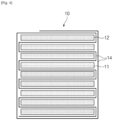
- FIG. 4 is a cross-sectional view illustrating an electrode assembly manufactured by the electrode assembly manufacturing apparatus.
- the electrode assembly manufacturing apparatus 100 is an apparatus for manufacturing an electrode assembly 10 by stacking the first electrode 11, the separator 14, and the second electrode 12.
- the electrode assembly 10 is a chargeable/dischargeable power generating element, and may be formed in a form in which the first electrode 11, the separator 14, and the second electrode 12 are alternately stacked and aggregated.
- the separator 14 may be folded in a zigzag shape, and the first electrode 11 and the second electrode 12 may be alternately disposed between the folded separators 14.
- the electrode assembly 10 may be provided in a form in which the outermost portion is surrounded by the separator 14, e.g., by wrapping the separator around the assembled electrode assembly 10, as illustrated in FIG. 4 .
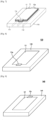
- FIG. 5 is a perspective view illustrating the press unit in the electrode assembly manufacturing apparatus which can be used in an exemplary embodiment f the method of the present invention
- FIG. 6 is a perspective view illustrating an example of a state in which the press unit presses a stack. More specifically, FIG. 6 illustrates the above-described secondary heat press operation.
- the press unit 180 may press the first electrode(s) 11, separator 14, and second electrode(s) 12 which are stacked while being heated to bond the first electrode(s) 11, the separator 14, and the second electrode(s) 12.
- the press unit 180 includes a pair of pressing blocks 181 and 182, and the pair of pressing blocks 181 and 182 are moved towards one another to effect the pressing of the stack S comprising the stacked first electrode(s) 11, the separator 14, and the second electrode(s) 12.
- the press unit 180 further includes press heaters 183 and 184 for heating the pair of pressing blocks 181 and 182, and the pair of pressing blocks 181 and 182 may heat and press the stack S. Accordingly, when the stack S is pressed with the press unit 180, thermal fusion between the first electrode(s) 11, the separator 14, and the second electrode(s) 12 is better achieved, so that stronger adhesion may be possible.
- the separator supply unit 120 may have a passage through which the separator 14 passes towards the stack table 110.
- the separator supply unit 120 may further include a separator roll 122 on which the separator 14 is wound.
- the separator 14 wound on the separator roll 122 may be gradually unwound and pass through the formed passage to be supplied to the stack table 110.
- FIG. 8 is a perspective view illustrating a first electrode seating table in the electrode assembly manufacturing apparatus.
- the first electrode supply unit 130 may supply the first electrode 11 to the first electrode stack unit 150.
- the first electrode supply unit 130 may include a first electrode seating table 131 on which the first electrode 11 is seated before being stacked on the stack table 110 by the first electrode stack unit 150.
- the first electrode supply unit 130 may further include a first electrode roll 133 on which the first electrode 11 is wound in the form of a sheet, a first cutter 134 for cutting the first electrode 11 at regular intervals to form the first electrodes 11 of a predetermined size when the first electrode 11 is unwound and supplied from the first electrode roll 133, a first conveyor belt 135 for moving the first electrode 11 cut by the first cutter 134, and a first electrode supply head 136 for picking up (e.g., via vacuum suction) the first electrode 11 transferred by the first conveyor belt 135 and seating the first electrode on the first electrode seating table 131.
- the first cutter 134 may cut the sheet-shaped first electrode 11 in such a way as to define a first electrode tab 11a protruding from the end thereof.
- FIG. 9 is a perspective view illustrating a second electrode seating table in the electrode assembly manufacturing apparatus.
- the second electrode supply unit 140 may supply the second electrode 12 to the second electrode stack unit 160.
- the second electrode supply unit 140 may include a second electrode seating table 141 on which the second electrode 12 is seated before being stacked on the stack table 110 by the second electrode stack unit 160.
- the second electrode supply unit 140 may further include a second electrode roll 143 on which the second electrode 12 is wound in the form of a sheet, a second cutter 144 for cutting the second electrode 12 at regular intervals to form the second electrode 12 of a predetermined size when the second electrode 12 is unwound and supplied from the second electrode roll 143, a second conveyor belt 145 for moving the second electrode 121 cut by the second cutter 144, and a second electrode supply head 146 for picking up (e.g., via vacuum suction) the second electrode 12 transferred by the second conveyor belt 145 and seating the second electrode on the second electrode seating table 141.
- the second cutter 144 may cut the sheet-shaped second electrode 12 in such a way as to define a second electrode tab 12a protruding from the end thereof.
- FIG. 10 is a perspective view illustrating a first suction head in the electrode assembly manufacturing apparatus which can be used in an exemplary embodiment of the method of the present invention
- FIG. 11 is a bottom view illustrating the first suction head in the electrode assembly manufacturing apparatus.
- the first electrode stack unit 150 may stack the first electrode 11 on the stack table 110.
- the first electrode stack unit 150 may include a first suction head 151 and a first moving unit 153.
- the first suction head 151 may pick up the first electrode 11 seated on the first electrode seating table 131 via vacuum suction.
- the first suction head 151 may be formed with one or more vacuum suction ports 151a formed on a bottom surface 151b of the first suction head 150 in order to apply suction to the first electrode 11 and thereby secure the first electrode 11 to the bottom surface 151b of the first suction head 151.
- a passage connecting the vacuum suction port 151a and a device for generating vacuum suction may be formed.
- the first moving unit 153 may move the first suction head 151 to the stack table 110 so as to allow the first suction head 151 to stack the first electrode 11 on the stack table 110.
- the holding mechanism 170 may hold the first electrode 11 or the second electrode 12 and secure the first electrode 11 or the second electrode 12 to the stack table 110. In doing so, the holding mechanism 170 may apply pressure to the upper surface of the stack S (i.e., the first electrode 11, the second electrode 12, or the separator 14 stacked on the uppermost end of the stack S). That is, when the first electrode(s) 11 and the second electrode(s) 12 are positioned in a stack S between layers of the separator 14, the holding mechanism 170 may grip the uppermost surface of the stack by pressing the stack towards the stack table 110 to prevent movement of the stack S with respect to the stack table 110.
- the holding mechanism 170 may grip the uppermost surface of the stack by pressing the stack towards the stack table 110 to prevent movement of the stack S with respect to the stack table 110.
- the separator 14 wound on the separator roll 122 is supplied while passing through the passage formed so that the separator can be stacked on the stack table 110.
- the first electrode stack unit 150 stacks the first electrode 11 on the upper surface of the separator 14 stacked on the stack table 110.
- the holding mechanism 170 then presses down on the upper surface of the first electrode 11 to secure the position of the first electrode 11 on the stack table 110.
- the separator 14 is continuously supplied so as to cover the upper surface of the first electrode 11.
- the second electrode 12 supplied from the second electrode supply unit 140 is then stacked by the second electrode stack unit 160 on a portion of the separator 14 where the separator 14 covers the upper surface of the first electrode 11. Then the holding mechanism 170 releases the upper surface of the first electrode 11 and then presses down on the upper surface of the second electrode 12 to secure the position of the stack S being built vis-a-vis the stack table 110.
- the stack S in which the separator 14 is zig-zag-folded and positioned between each of the successive first and second electrodes 11, 12 may be formed.
- the stack S is moved to the press unit 180, and the press unit 180 heats and presses the stack S, thus thermally bonding the components of the stack together (i.e., the heated first electrode(s) 11, separator 14, and second electrode(s) 12) so as to manufacture the electrode assembly 10.
- the press unit 180 heats and presses the stack S, thus thermally bonding the components of the stack together (i.e., the heated first electrode(s) 11, separator 14, and second electrode(s) 12) so as to manufacture the electrode assembly 10.
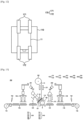
- the first press unit 50 may primarily heat and press the stack S in a fixed state.
- the first press unit 50 includes a pair of first pressing blocks 50a and 50b and may further include the gripper 51 configured for fixing the stack S.
- the gripper 51 may hold the stack S by pressing the upper and lower surfaces of the stack S towards one another along the stacking direction (along the y axis) to fix the relative positions of the first electrodes 11, the second electrodes 12, and the separator 14. As in the example shown, to hold these relative positions, the gripper 51 may press the upper and lower surfaces of the stack S.
- the pair of first pressing blocks 50a and 50b of the first press unit 50 may move in directions towards and away from each other. In moving towards each other, the pair of first pressing blocks 50a and 50b may compress either one or both of the stack S and the gripper 51.
- the first press unit 50 may heat and compress the stack S to reduce or eliminate any spaces between the first electrodes 11, the separator 14, and the second electrodes 12 included in the stack S, so as to bond such components of the stack S together.
- each pressing surface of the pair of first pressing blocks 50a and 50b configured for contact with and compression of the stack S may define planes.
- At least one of the pair of first pressing blocks 50a and 50b may include a gripper groove 52 having a shape corresponding to a fixing part 51b of the gripper 51 described further herein.
- each of the pair of first pressing blocks 50a and 50b include four gripper grooves 52 to correspond with four fixing parts 51b.
- the number of gripper grooves 52 should match the number of fixing parts to be used.
- the gripper 51 may include a main body 51a and a plurality of fixing parts 51b.
- the main body 51a may have a length along an x axis and a height along a y axis that are the same or approximately the same as the length and height of the stack S along those respective axes.
- the main body may be longer than the length of the stack S in the x axis and have a greater height than the height of the stack S in the y axis.
- the fixing parts 51b preferably may be in the form of a rod, column, or plate that extend along a width direction (z axis) of the stack S.
- the length of the stack S in the x axis may refer to the portion of the stack having the longest distance from one end to the other end of the stack S
- the height in the y axis may refer to the distance in the stacking direction of the stack S
- the width in the z axis may refer to a distance in a direction perpendicular to both the x and y axes.
- the fixing parts 51b may be provided in two rows in which one row is adjacent to a pressing surface of pressing block 50a while the other row is adjacent to a pressing surface of pressing block 50b.
- the position of each of the fixing parts 51b may be adjustable in the height direction of the main body 51a. In this manner, each of the fixing parts 51b may be placed in contact with, and preferably along the width of, the upper and lower surfaces of the stack S to fix the position of the stack S and the relative positions of the first electrode 11 and the second electrode 12 within the stack S.
- the second press unit 60 may heat and compress the stack S that was previously heated and compressed by the first press unit 50, so as to secondarily compress the already primarily compressed stack S.
- the second press unit 60 includes a pair of second pressing blocks 60a and 60b.
- the pair of pressing blocks 60a and 60b may be moved in directions towards and away from each other. In moving towards each other, the pair of pressing blocks 60a and 60b may press upon the upper and lower surfaces of the stack S to compress the stack.
- each pressing surface of the pair of second pressing blocks 60a and 60b configured for contact with and compression of the stack S may define planes.
- grooves for the fixing parts 51b may be excluded from the second pressing blocks 60a and 60b.
- at least one of the pair of second pressing blocks 60a and 60b may include one or more grooves having a shape corresponding to the fixing part 51b of the gripper 51.
- each of the pair of first pressing blocks 50a and 50b of the first press unit 50 include gripper grooves 52 having a shape corresponding to the fixing part 51b of the gripper 51, and each of the pair of second pressing blocks 60a and 60b of the second press unit 60 have flat pressing surfaces without any gripper grooves.
- the second press unit 60 may heat and press only a portion of the stack S on which the gripper 51 is (or was previously) located, which were not heated and pressed by the first press unit 50. In some other arrangements, the second press unit 50 may heat and press the entire upper and lower surfaces of the stack.
- the first press unit 50 may compress the heated stack S initially and with the upper surface and the lower surface of the stack S fixed with the gripper 51 to reduce or eliminate the spaces between, while bonding, the first electrodes 11, the separator 14, and the second electrodes 2 included in the stack S, so as to bond such components of the stack S together in the regions of the stack S in which the gripper 51 is not located.
- the second press unit 60 may compress and heat the stack S which has already been preliminarily bonded by the first press unit 50, and from which the gripper 51 has been removed.
- the second press unit 60 may thus reduce or eliminate any spaces between the first electrodes 11, the separator 4, and the second electrodes 12 included in the stack S, so as to bond such components of the stack S together in the regions of the stack S in which the gripper 51 previously pressed the stack S during the initial pressing operation by the first press unit 50.
- each of the pair of second pressing blocks 60a and 60b may be a quadrangular block in the form of a rectangular parallelepiped. In such arrangements, the pair of second pressing blocks 60a and 60b may have the flat pressing surfaces described previously herein.
- each of the pair of first pressing blocks 50a and 50b of the first press unit 50 may have the flat pressing surfaces.
- each of the pair of second pressing blocks 60a and 60b of the second press unit 60 may have grooves having the shape corresponding to the fixing parts 51b of the gripper 51.
- the fixing part 51b may include a heat-conducting material, such as a thermally conductive metal material selected from the group consisting of aluminum and iron.
- the second press unit 60 may not compress regions of the stack S on which the gripper 51 was previously located, but may instead only compress regions of the stack S where the gripper was not previously located and upon which the press unit 50 did not press during the initial pressing.
- each of the pair of first pressing blocks 50a and 50b may be a quadrangular block in the form of a rectangular parallelepiped. In such arrangements, the pair of first pressing blocks 50a and 50b may have the flat pressing surfaces described previously herein.
- Either one or both of the first and second press units 50 and 60 preferably include a press heater (not illustrated), configured for heating the respective pair of first and second pressing blocks 50a, 50b, 60a, and 60b such that the blocks may heat the stack S when pressing upon the stack.
- a press heater not illustrated
- thermal fusion between the first electrodes 11, the separator 14, and the second electrodes 12 may be better achieved such that stronger bond may be formed among these layers.
- both the length and the width of the respective pressing surfaces may be greater than the corresponding length and width (in the x and z axes, respectively) of the stack S.
- the electrode assembly manufacturing apparatus 100 configured as described above, by thermally bonding the components of the stack S to one another, may desirably prevent the stack S from falling apart or the components of the stack S from shifting their positions within the stack S.
- FIG. 13 is a front elevation view conceptually illustrating an electrode assembly manufacturing apparatus according to another exemplary embodiment.
- the holding mechanism is omitted for convenience, and the press unit 180 located on the rear side in a top plan view is illustrated with dotted lines.
- an apparatus 200 for manufacturing an electrode assembly includes a stack table 110; a separator supply unit 120 for supplying a separator 14; a first electrode supply unit 130 for supplying a first electrode 11; a second electrode supply unit 140 for supplying a second electrode 12; a first electrode stack unit 150 for stacking the first electrode 11 on the stack table 110; a second electrode stack unit 160 for stacking the second electrode 12 on the stack table 110; a press unit 180 for bonding the first electrode 11, the separator 14, and the second electrode 12 to each other; and a holding mechanism 170 for securing the positions of the stack S on the stack table 110 (see FIG. 12 ).
- the apparatus 200 may further include a rotating unit R for rotating the stack table 110 and a vision device 290 for inspecting the first and second electrodes 11 and 12.
- the vision device 290 of the apparatus 200 may include a first camera 291 and a second camera 292.
- the first camera 291 may photograph the first electrode 11 seated on the first electrode seating table 131 in the first electrode supply unit 130
- the second camera 292 may photograph the second electrode 12 seated on the second electrode seating table 141 in the second electrode supply unit 140.
- the stacking quality of the first electrode 11 and the second electrode 12 may thereby be inspected through image information obtained by the first camera 291 and the second camera 292. For example, the seating positions, sizes, and stacking states of the first electrode 11 and the second electrode 12 may thus be inspected.
- the rotating unit R may rotate the stack table 110 in one direction r1 and the other direction r2.
- a first electrode stack unit 150 may be provided on one side of the rotating unit R
- the second electrode stack unit 160 may be provided on the other side of the rotating unit R.
- the rotating unit R may thus rotate the stack table 110 to one side so as to face a first suction head 151 when the first electrode 11 is stacked, and may rotate the stack table 110 to the other side so as to face a second suction head 161 when the second electrode 12 is stacked.
- the zig zag folding of the separator 14 between each successive one of the first and second electrodes 11, 12, as shown in FIG. 4 may thus be achieved.
- the apparatus 200 of the present embodiment and all of its subcomponents operates in the same manner as the apparatus 100 of the previously-described embodiment, except as otherwise stated.
- the stacking quality of the first electrode 11 may be inspected via the vision device 290.
- the second electrode 12 is supplied and seated on the second electrode seating table 141 of the second electrode supply unit 140, the stacking quality of the second electrode 12 may be inspected via the vision device 290.
- the positive electrode may be manufactured by, for example, coating a positive electrode current collector with a positive electrode coating mixture comprising a positive electrode active material, a conductive material, and a binder and then drying the coating mixture. If necessary, a filler may be added to the mixture.
- a positive electrode coating mixture comprising a positive electrode active material, a conductive material, and a binder and then drying the coating mixture. If necessary, a filler may be added to the mixture.
- Such materials may be any appropriate materials used in the relevant field, in particular those commonly used for the particular application.
- the materials that may be used for the positive electrode current collector is not particularly limited.
- the positive electrode current collector preferably has a relatively high conductivity without causing a chemical change when used in a battery.
- stainless steel; aluminum; nickel; titanium; calcined carbon; or a material in which a surface of aluminum or stainless steel is treated with carbon, nickel, titanium, silver, and the like may be used.
- the positive electrode current collector may be aluminum. Adhesion between the current collector and the positive electrode coating mixture desirably may be increased by including fine irregularities on a surface of the current collector interfacing with the coating mixture.
- the positive electrode current collector may be used, such as a film, a sheet, a foil, a net, a porous body, a foam body, and a non-woven body.
- the positive electrode current collector generally may have a thickness in a range from 3 ⁇ m to 500 ⁇ m.
- the conductive material in the positive electrode coating mixture generally may be included in an amount from 1 to 50 wt% of the total weight of the mixture including the positive electrode active material.
- the conductive material is not particularly limited and preferably has conductivity without causing a chemical change when used in a battery.
- graphite such as natural graphite and artificial graphite
- carbon black such as carbon black, acetylene black, Ketjen black, channel black, furnace black, lamp black, and summer black
- conductive fibers such as carbon fibers and metal fibers
- carbon and metal powders such as carbon fluoride, aluminum, and nickel powder
- conductive whiskeys such as zinc oxide and potassium titanate
- conductive metal oxides such as titanium oxide
- polyphenylene derivatives may be used for the conductive material.
- the binder in the positive electrode coating mixture assists in bonding between the active material and the conductive material in bonding the coating mixture to the current collector.
- Such binder is generally included in an amount from 1 to 50% by weight of the total weight of the mixture including the positive electrode active material.
- the binder may include polyvinylidene fluoride, polyvinyl alcohol, carboxymethylcellulose (CMC), starch, hydroxypropylcellulose, regenerated cellulose, polyvinylpyrrolidone, tetrafluoroethylene, polyethylene, polypropylene, ethylene-propylene-diene terpolymer (EPDM), sulfonated EPDM, styrene butylene rubber, fluororubber, and various copolymers.
- the filler optionally added to the positive electrode coating mixture may be used as a component to suppress the expansion of the positive electrode.
- a filler is not particularly limited and may include a fibrous material that does not cause a chemical change when used in a battery.
- olefin polymers such as polyethylene and a polypropylene
- fibrous materials such as glass fiber and carbon fiber, may be used.
- the negative electrode may be manufactured by coating, drying, and pressing a negative electrode active material on a negative electrode current collector, and, if necessary, the conductive materials, binders, fillers, and the like discussed above may be optionally further included.
- any appropriate materials used in the relevant field may be used, in particular those commonly used for the particular application.
- carbon such as non-graphitizable carbon and graphitic carbon
- metal composite oxide represented by the chemical formulas LixFe 2 O 3 (0 ⁇ x ⁇ 1), Li x WO 2 (0 ⁇ x ⁇ 1), Sn x Me 1-x Me'yOz (Me: Mn, Fe, Pb, Ge; Me': Al, B, P, Si, elements of groups 1, 2 and 3 of the periodic table, and halogens; 0 ⁇ x ⁇ 1; 1 ⁇ y ⁇ 3; 1 ⁇ z ⁇ 8); lithium metal; lithium alloys; silicon-based alloys; tin-based alloys; metal oxides, such as SnO, SnO 2 , PbO, PbO 2 , Pb 2 O 3 , Pb 3 O 4 , Sb 2 O 3 , Sb 2 O 4 , Sb 2 O 5 , GeO, GeO 2 , Bi 2 O 3 , Bi 2 O 4 , and Bi 2 O 5 ; conductive polymers, such as polyacet
- the negative electrode current collector may also be used, such as a film, a sheet, a foil, a net, a porous body, a foam body, a non-woven body, and the like.
- the negative electrode current collector may have a thickness generally in a range of 3 ⁇ m to 500 ⁇ m.
- the separator may be an organic/inorganic complex porous SRS (Safety-Reinforcing Separator).
- SRS may have a structure in which a coating layer component including inorganic particles and a binder polymer is coated on a polyolefin-based separator substrate.
- the SRS does not undergo high-temperature thermal contraction due to the heat resistance of the component inorganic particles, even if the electrode assembly is penetrated by a needle-shaped conductor, an elongated length of the safety separator can be maintained.
- the SRS may have a uniform porous structure formed by an interstitial volume between the inorganic particles that are components of the coating layer, in addition to the porous structure of the separator substrate itself.
- the pores may not only significantly alleviate any external impacts applied to the electrode assembly, but may also facilitate the movement of lithium ions through the pores, as well as enable a large amount of electrolyte to be impregnated into the separator, thereby promoting improved performance of the battery.
- the separator may be dimensioned in its width dimension (orthogonal to the longitudinal dimension in which the separator is unrolled) such that separator portions extend outwardly on both sides beyond corresponding edges of adjacent positive and negative electrodes (hereinafter "surplus portions").
- such outwardly extending portions of the separator may have a structure including a coating layer thicker than a thickness of the separator formed on one or both sides of the separator in order to prevent shrinkage of the separator.
- each separator surplus portion may have a size of 5% to 12% of the width of the separator.
- the coating layer may be coated on both surfaces of the separator over a width of 50% to 90% of the width of each separator surplus portion.
- the widths of the coating layers may be the same or different on each surface of the separator.
- the coating layer may include inorganic particles and a binder polymer as components.
- polyolefin-based separator component may include high-density polyethylene, linear low-density polyethylene, low-density polyethylene, ultra-high molecular weight polyethylene, polypropylene, or derivatives thereof.
- the thickness of the coating layer may be smaller than the thickness of the first electrode or the second electrode. In some such arrangements, the thickness of the coating layer may be 30% to 99% of the thickness of the first electrode or the second electrode.
- the coating layer may be formed by wet coating or dry coating.
- the polyolefin-based separator substrate and the coating layer may exist in a form in which pores on the surface of the substrate and the coating layer are anchored with each other, whereby the separator substrate and the coating layer may be bonded together firmly.
- the substrate and the coating layer of the separator may have a thickness ratio from 9: 1 to 1: 9.
- a preferred thickness ratio may be 5: 5.
- the inorganic particles may be inorganic particles commonly used in the art.
- the inorganic particles may interact with each other to form micropores in the form of empty spaces between the inorganic particles while structurally helping to maintain the physical shape of the coating layer.
- the inorganic particles since the inorganic particles generally have properties that do not change their physical properties even at high temperatures of 200°C or more, the resultant organic/inorganic complex porous film generally and desirably has excellent heat resistance.
- the materials that may be used for the inorganic particles are not particularly limited but are preferably electrochemically stable. That is, the inorganic particles are preferably selected such that oxidation and/or reduction reactions do not occur in the operating voltage range of the applied battery (for example, 0 to 5 V based on Li/Li+).
- the use of inorganic particles having ion transport ability may improve performance by increasing the ionic conductivity in the electrochemical device. Thus, use of inorganic particles having ionic conductivity as high as possible is preferable.
- the inorganic particles have a high density, it is difficult to disperse the inorganic particles during coating, and it can also undesirably increase the weight of the battery.
- inorganic particles having density as low as possible are preferable.
- inorganic materials having a high dielectric constant contribute to an increase in the degree of dissociation of electrolyte salt, such as a lithium salt, in a liquid electrolyte, thereby improving the ionic conductivity of the electrolyte.
- the inorganic particles may be at least one type selected from the group consisting of inorganic particles having piezoelectricity and inorganic particles having lithium ion transport ability.
- Inorganic particles having piezoelectricity refer to materials which are a non-conductor at normal pressure, but have a property of conducting electricity due to a change in the internal structure when a certain pressure is applied. They are also materials which exhibit high permittivity characteristics with a permittivity constant of 100 or more. Inorganic particles having piezoelectricity also generate an electric potential difference between opposing surfaces, e.g., of a separator, by causing one surface to be positively charged and the other surface to be negatively charged, or vice versa, when either tension or compression is applied to an object composed of the inorganic particles, e.g., a separator.
- the inorganic particles having the above characteristics are used as a coating layer component, in the case of an internal short circuit of both electrodes due to an external impact, such as by a needle-shaped conductor, the positive electrode and the negative electrode may not directly contact one another due to the inorganic particles coated on the separator. Moreover, due to the piezoelectricity of the inorganic particles, an electric potential difference may occur within the particles, which desirably may result in electron movement between both electrodes (i.e., the flow of a minute current), so that it may be possible to gently reduce the voltage of the battery, thereby improving safety.
- Examples of materials for the inorganic particles having piezoelectricity may be one or more selected from the group consisting of BaTiO 3 , Pb(Zr,Ti)O 3 (PZT), those represented by the chemical formula Pb 1-x La x Zr 1-y Ti y O 3 (PLZT), PB(Mg 3 Nb 2/3 )O 3 -PbTiO 3 (PMN-PT), and hafnia (HfO 2 ), but are not limited to these materials.
- PZT Pb(Zr,Ti)O 3
- PZT Pb(Zr,Ti)O 3
- PMN-PT PB(Mg 3 Nb 2/3 )O 3 -PbTiO 3
- HfO 2 hafnia
- Inorganic particles having lithium-ion transport ability refer to inorganic particles containing a lithium element but not storing lithium and instead having a function of moving lithium ions.
- the inorganic particles having lithium-ion transport ability are capable of transporting and moving lithium ions due to a kind of defect in the particle structure. As a result, the lithium-ion conductivity in the battery may be improved, thereby improving battery performance.
- Examples of materials for the inorganic particles having lithium-ion transport ability may be one or more selected from the group consisting of lithium phosphate (Li 3 PO 4 ), lithium titanium phosphate (represented by the chemical formula Li x Ti y (PO 4 ) 3 , wherein 0 ⁇ x ⁇ 2, 0 ⁇ y ⁇ 3), lithium aluminum titanium phosphate (represented by the chemical formula Li x Al y Ti z (PO 4 ) 3 , wherein 0 ⁇ x ⁇ 2, 0 ⁇ y ⁇ 1, 0 ⁇ z ⁇ 3), glass of the series represented by the chemical formula (LiAlTiP) x O y (0 ⁇ x ⁇ 4, 0 ⁇ y ⁇ 13), lithium lanthanum titanate (represented by the chemical formula Li x La y TiO 3 , wherein 0 ⁇ x ⁇ 2, 0 ⁇ y ⁇ 3), lithium germanium thiophosphate (represented by the chemical formula Li x Ge y P z S w , wherein 0 ⁇ x ⁇ 4, 0 ⁇ y ⁇ 1, 0 ⁇ z ⁇ 1, 0
- composition ratio of the inorganic particles and the binder polymer, which are components of the coating layer of the separator is not particularly limited, but may be adjusted within the range of 10:90 to 99:1 by weight%, and preferably within the range of 80:20 to 99:1 by weight%.
- the composition ratio is less than 10:90 by weight%, the content of the polymer may become excessively large and the pore size and porosity may be reduced due to a decrease in the empty space formed between the inorganic particles, finally resulting in deterioration of the battery performance.
- composition ratio exceeds 99:1 by weight%, the content of the polymer may be too small, and the mechanical properties of the final organic/inorganic composite porous separator may become deteriorated due to weakened adhesive force between the inorganic materials.
- a binder polymer commonly used in the art may be used as the binder polymer.
- the coating layer may be referred to as an active layer.
- the positive electrode and the negative electrode were supplied after being cut from a positive electrode sheet and a negative electrode sheet, respectively, and the separator was supplied in the form of an elongated separator sheet. Thereafter, the supplied separator was folded while rotating the stack table and stacking the positive electrodes and the negative electrode as described above. A gripper was used to press down on and stabilize the stack, which resulted in a stack including 39 electrodes.
- a primary heat press operation was performed in a press unit by gripping the stack with the gripper and pressing for 15 seconds while heating the stack under a temperature condition of 50°C and a pressure condition of 1.46 MPa.
- a pre-heating operation was performed, in which the gripper was disengaged from the stack, the temperature of the pressing blocks of the press unit were maintained at 60°C (temperature condition), and a pressure of 1 MPa (pressure condition) was applied to the stack with the pressing blocks of the press unit for 15 seconds (press time).
- the secondary heat press operation was performed, in which the temperature of the pressing blocks were maintained at 60°C (temperature condition) and a pressure of 1.8 MPa (pressure condition) was applied to the stack with the pressing blocks for 7 seconds (press time).
- Electrode assemblies of Examples 2 to 5 were manufactured in the same method as the electrode assembly manufacturing method in Example 1, except that the method was performed under the temperature conditions, pressure conditions, and press time represented in Table 1 below.
- Electrode assemblies of Comparative Examples 1 to 17 were manufactured by performing the primary and secondary heat press operations in the same method as the electrode assembly manufacturing method of Example 1, except that the method was performed under the temperature conditions, pressure conditions, and press time represented in Tables 2 and 3 below. That is, in the case of Comparative Examples 1 to 12, the pre-heating operation was not performed.
- Withstand voltages of the electrode assembles of Examples 1 to 5, and the electrode assemblies of Comparative Examples 1 to 12 were measured.
- the voltage applied to the electrode assemblies of Examples 1 to 5 and Comparative Examples 1 to 12 was increased from 0 V to 4000 V, and the voltage value at the point in time when the leakage current became 0.6 mA or more was measured and determined to be the withstand voltage values.
- the main factor that causes damage to the electrode assembly is a pressure condition.
- Adhesive forces between surfaces at the upper end, the lower end, and the middle of the stack S were measured by disassembling (i.e., separating the layers of) the electrode assemblies of Examples 1 to 6 and Comparative Examples 4, 8, and 11 to 17 (in which the separation of the electrodes and separator were not observed before 60 seconds in the previous test) and then analyzing the separated layers. Specifically, adhesive force between the negative electrode and the separator located at the lowermost end of the stack was measured. Additionally, adhesive force between the negative electrode and the separator located at the uppermost end of the stack was measured. Finally, adhesive force between the negative electrode and the separator located at a midle location along the stacking direction of the stack was measured
- the negative electrode and the separator sampled had a width of 55 mm and a length of 20 mm.
- the sampled sample was adhered to the slide glass with the electrode being positioned on the adhesive surface of the slide glass. After that, the slide glass with the sample was mounted to the adhesive force measuring device and tested by performing 90° peel test at a speed of 100 mm/min pursuant to the testing method set forth in ASTM-D6862, as discussed above. After discounting any initial significant fluctuations, the values for applied force per sample width (in grams/mm) were measured while the separator was peeled away from the electrode.
Landscapes
- Chemical & Material Sciences (AREA)
- Chemical Kinetics & Catalysis (AREA)
- Electrochemistry (AREA)
- General Chemical & Material Sciences (AREA)
- Engineering & Computer Science (AREA)
- Manufacturing & Machinery (AREA)
- Secondary Cells (AREA)
- Cell Separators (AREA)
- Inert Electrodes (AREA)
Claims (12)
- Verfahren zur Herstellung einer Elektrodenanordnung (10), umfassend das Zusammensetzen eines Elektrodenstapels, der eine Vielzahl von Elektroden (11, 12) enthält, die entlang einer Stapelachse gestapelt sind, wobei ein jeweiliger Separatorabschnitt (14) zwischen jeder der Elektroden positioniert ist;nach dem Zusammensetzen des Elektrodenstapels, Durchführen eines primären Wärmepressvorgangs an dem Elektrodenstapel, wobei der primäre Wärmepressvorgang das Aufbringen von Wärme und Druck auf den Elektrodenstapel umfasst;nach dem primären Wärmepressvorgang, Durchführen eines Vorheizvorgangs an dem Elektrodenstapel; undnach dem Vorheizvorgang, Durchführen eines sekundären Wärmepressvorgangs an dem Elektrodenstapel, wobei der sekundäre Wärmepressvorgang das Anwenden von Wärme und Druck auf den Elektrodenstapel umfasst, wobei der Vorheizvorgang das Anwenden von Wärme und Druck auf den Elektrodenstapel für eine Zeitdauer von 10 Sekunden bis 40 Sekunden unter einer Druckbedingung von 0,5 MPa bis 2 MPa und unter einer Temperaturbedingung von 50°C bis 85°C beinhaltet, und wobei die Druckbedingung, die in dem Vorheizvorgang angewendet wird, das Aufbringen eines niedrigeren Drucks umfasst als derjenige, der in dem primären Wärmepressvorgang und dem sekundären Wärmepressvorgang aufgebracht wird.
- Verfahren nach Anspruch 1, wobei der primäre Wärmepressvorgang das Ineingriffbringen des Elektrodenstapels mit einem Greifer (51a, 51b) umfasst, um eine Position des Elektrodenstapels zu sichern, und wobei das Aufbringen von Wärme und Druck auf den Elektrodenstapel während des primären Wärmepressvorgangs erfolgt, während der Greifer mit dem Elektrodenstapel in Eingriff ist.
- Verfahren nach Anspruch 2, ferner umfassend das Lösen des Greifers von dem Elektrodenstapel vor der Durchführung des Vorheizvorgangs.
- Verfahren nach Anspruch 1, wobei die Separatorabschnitte Abschnitte eines länglichen Separatorblatts sind und wobei der Schritt des Zusammensetzens des Elektrodenstapels das abwechselnde Stapeln einer ersten der Elektroden und einer zweiten der Elektroden auf dem länglichen Separatorblatt umfasst, wobei das längliche Separatorblatt nacheinander über eine zuvor gestapelte der ersten und zweiten Elektroden gefaltet wird, bevor eine nachfolgende der ersten und zweiten Elektroden gestapelt wird.
- Verfahren nach Anspruch 4, wobei der Schritt des Zusammensetzens des Elektrodenstapels umfasst:(1) Positionieren des länglichen Separatorblatts auf einem Stapeltisch (110);(2) Stapeln einer der ersten Elektroden auf einer oberen Fläche des länglichen Separatorblatts;(3) Drehen des Stapeltisches, während eine obere Fläche der einen der ersten Elektroden mit dem länglichen Separatorblatt abgedeckt wird; und(4) Stapeln einer der zweiten Elektroden auf einem Teil des länglichen Separatorblechs, das die obere Fläche der einen der ersten Elektroden bedeckt, wobei die obigen Schritte (1) bis (4) ein oder mehrere Male wiederholt werden.
- Verfahren nach Anspruch 4, ferner umfassend die Verwendung einer Kamera (291, 292), um die Stapelung der ersten Elektrode oder der zweiten Elektrode zu überprüfen.
- Verfahren nach Anspruch 1, wobei der primäre Wärmepressvorgang das Aufbringen von Wärme und Druck auf den Elektrodenstapel während einer Zeitspanne von 5 Sekunden bis 20 Sekunden unter einer Temperaturbedingung von 45°C bis 75°C und unter einer Druckbedingung von 1 MPa bis 2,5 MPa umfasst.
- Verfahren nach Anspruch 1, wobei der sekundäre Wärmepressvorgang das Aufbringen von Wärme und Druck auf den Elektrodenstapel während einer Zeitspanne von 5 Sekunden bis 10 Sekunden unter einer Temperaturbedingung von 50°C bis 85°C und unter einer Druckbedingung von 1 MPa bis 2,5 MPa umfasst.
- Verfahren nach Anspruch 1, wobei der Schritt des Aufbringens von Druck auf den Elektrodenstapel sowohl im primären als auch im sekundären Wärmepressvorgang das Vorschieben eines Pressblocks entlang der Stapelachse und in Eingriff mit dem Elektrodenstapel umfasst.
- Verfahren nach Anspruch 9, wobei der Pressblock erhitzt wird, um Wärme auf den Elektrodenstapel zu übertragen.
- Verfahren nach Anspruch 1, wobei der Schritt des Zusammensetzens des Elektrodenstapels das Wickeln eines länglichen Separatorblatts um einen Außenumfang des Elektrodenstapels umfasst.
- Verfahren nach Anspruch 1, das ferner das Erhitzen mindestens einer der Elektroden und der Separatorteile vor dem Schritt des Zusammensetzens des Elektrodenstapels umfasst.
Applications Claiming Priority (4)
| Application Number | Priority Date | Filing Date | Title |
|---|---|---|---|
| KR20210090600 | 2021-07-09 | ||
| KR20210090601 | 2021-07-09 | ||
| KR20210090592 | 2021-07-09 | ||
| PCT/KR2022/010001 WO2023282715A1 (en) | 2021-07-09 | 2022-07-08 | Manufacturing method for electrode assembly |
Publications (3)
| Publication Number | Publication Date |
|---|---|
| EP4256637A1 EP4256637A1 (de) | 2023-10-11 |
| EP4256637A4 EP4256637A4 (de) | 2024-09-04 |
| EP4256637B1 true EP4256637B1 (de) | 2025-06-25 |
Family
ID=84801815
Family Applications (3)
| Application Number | Title | Priority Date | Filing Date |
|---|---|---|---|
| EP25192249.8A Pending EP4636886A3 (de) | 2021-07-09 | 2022-07-08 | Elektrodenanordnung |
| EP22838066.3A Active EP4256637B1 (de) | 2021-07-09 | 2022-07-08 | Herstellungsverfahren für elektrodenanordnung |
| EP22838065.5A Active EP4248513B1 (de) | 2021-07-09 | 2022-07-08 | Elektrodenanordnung |
Family Applications Before (1)
| Application Number | Title | Priority Date | Filing Date |
|---|---|---|---|
| EP25192249.8A Pending EP4636886A3 (de) | 2021-07-09 | 2022-07-08 | Elektrodenanordnung |
Family Applications After (1)
| Application Number | Title | Priority Date | Filing Date |
|---|---|---|---|
| EP22838065.5A Active EP4248513B1 (de) | 2021-07-09 | 2022-07-08 | Elektrodenanordnung |
Country Status (7)
| Country | Link |
|---|---|
| EP (3) | EP4636886A3 (de) |
| JP (2) | JP7575024B2 (de) |
| KR (6) | KR102569078B1 (de) |
| ES (2) | ES3037164T3 (de) |
| HU (2) | HUE072344T2 (de) |
| PL (1) | PL4248513T3 (de) |
| WO (2) | WO2023282715A1 (de) |
Families Citing this family (2)
| Publication number | Priority date | Publication date | Assignee | Title |
|---|---|---|---|---|
| CN116670912A (zh) * | 2021-07-09 | 2023-08-29 | 株式会社Lg新能源 | 电极组件 |
| KR20250149028A (ko) * | 2024-04-08 | 2025-10-15 | 주식회사 엘지에너지솔루션 | 전극 조립체의 정렬 및 손상 검사 방법 |
Family Cites Families (25)
| Publication number | Priority date | Publication date | Assignee | Title |
|---|---|---|---|---|
| US5916515A (en) | 1997-02-27 | 1999-06-29 | Valence Technology, Inc. | Two-stage lamination process |
| JP5135678B2 (ja) * | 2005-11-24 | 2013-02-06 | 日産自動車株式会社 | 電池構造体、組電池、およびこれらを搭載した車両 |
| JP5259453B2 (ja) * | 2009-02-25 | 2013-08-07 | 富士重工業株式会社 | 蓄電デバイスおよびその製造方法 |
| JP5682166B2 (ja) | 2010-07-28 | 2015-03-11 | アイシン精機株式会社 | 電池積層体の製造方法および電池積層体の製造装置 |
| US8962386B2 (en) | 2011-11-25 | 2015-02-24 | Semiconductor Energy Laboratory Co., Ltd. | Semiconductor device and method for manufacturing the same |
| KR20130132230A (ko) | 2012-05-25 | 2013-12-04 | 주식회사 엘지화학 | 단차를 갖는 전극 조립체 및 이를 포함하는 전지셀, 전지팩 및 디바이스 |
| KR101704759B1 (ko) * | 2012-11-12 | 2017-02-08 | 주식회사 엘지화학 | 스택/폴딩형 전극조립체 및 그를 포함하는 전기화학소자 |
| KR101602908B1 (ko) * | 2012-11-20 | 2016-03-11 | 주식회사 엘지화학 | 전극조립체 및 그를 포함하는 전기화학소자 |
| KR101561735B1 (ko) | 2013-09-25 | 2015-10-19 | 주식회사 엘지화학 | 전극조립체 제조방법 |
| KR101595621B1 (ko) * | 2013-09-27 | 2016-02-18 | 주식회사 엘지화학 | 전극조립체 제조방법 |
| KR102604599B1 (ko) * | 2015-04-02 | 2023-11-22 | 에스케이이노베이션 주식회사 | 리튬 이차전지용 복합 분리막 및 이의 제조방법 |
| KR102279304B1 (ko) | 2015-10-19 | 2021-07-21 | 삼성전기주식회사 | 촬상 광학계 |
| JP6641242B2 (ja) | 2016-07-05 | 2020-02-05 | キヤノントッキ株式会社 | 蒸着装置及び蒸発源 |
| KR102016645B1 (ko) * | 2016-07-08 | 2019-08-30 | 주식회사 엘지화학 | 전극 조립체 및 그의 제조 방법 |
| KR102065131B1 (ko) * | 2016-10-05 | 2020-03-02 | 주식회사 엘지화학 | 전극 조립체 및 이의 제조 방법 |
| KR102264685B1 (ko) * | 2016-11-30 | 2021-06-15 | (주)엘지에너지솔루션 | 전극조립체 제조장치 및 전극조립체를 제조하는 방법 |
| WO2018116295A1 (en) * | 2016-12-19 | 2018-06-28 | StoreDot Ltd. | Layer preparation, treatment, transfer and lamination in cell stack assembly processes for lithium ion batteries |
| KR102256438B1 (ko) * | 2017-03-20 | 2021-06-03 | 주식회사 엘지화학 | 2종의 분리막을 포함하는 스택-폴딩형 전극조립체 |
| US10490843B2 (en) * | 2017-04-10 | 2019-11-26 | Nano And Advanced Materials Institute Limited | Flexible battery with 180 degree operational bend radius |
| JP7170424B2 (ja) * | 2018-05-16 | 2022-11-14 | 旭化成株式会社 | 微多孔膜の製造方法およびそれを用いた微多孔膜 |
| KR102578215B1 (ko) * | 2018-08-27 | 2023-09-14 | 주식회사 엘지에너지솔루션 | 전극 조립체 제조장치 |
| KR102578204B1 (ko) * | 2018-08-27 | 2023-09-14 | 주식회사 엘지에너지솔루션 | 전극 조립체 제조장치 |
| KR102328527B1 (ko) * | 2018-12-24 | 2021-11-18 | 주식회사 엘지에너지솔루션 | 벤딩 현상이 개선된 스택형 전극 조립체 및 이의 제조방법 |
| KR102761334B1 (ko) * | 2019-01-30 | 2025-02-04 | 주식회사 엘지에너지솔루션 | 전극 조립체와 이차전지의 제조 방법 및 제조 장치 |
| CN114270585B (zh) | 2019-09-05 | 2024-06-07 | 株式会社Lg新能源 | 二次电池及制造该二次电池的方法 |
-
2022
- 2022-07-08 JP JP2023541891A patent/JP7575024B2/ja active Active
- 2022-07-08 EP EP25192249.8A patent/EP4636886A3/de active Pending
- 2022-07-08 ES ES22838066T patent/ES3037164T3/es active Active
- 2022-07-08 EP EP22838066.3A patent/EP4256637B1/de active Active
- 2022-07-08 KR KR1020220084641A patent/KR102569078B1/ko active Active
- 2022-07-08 KR KR1020220084639A patent/KR102569077B1/ko active Active
- 2022-07-08 HU HUE22838066A patent/HUE072344T2/hu unknown
- 2022-07-08 ES ES22838065T patent/ES3046132T3/es active Active
- 2022-07-08 WO PCT/KR2022/010001 patent/WO2023282715A1/en not_active Ceased
- 2022-07-08 EP EP22838065.5A patent/EP4248513B1/de active Active
- 2022-07-08 JP JP2023539386A patent/JP7666836B2/ja active Active
- 2022-07-08 WO PCT/KR2022/010000 patent/WO2023282714A1/en not_active Ceased
- 2022-07-08 PL PL22838065.5T patent/PL4248513T3/pl unknown
- 2022-07-08 HU HUE22838065A patent/HUE073305T2/hu unknown
-
2023
- 2023-08-16 KR KR1020230106930A patent/KR102608540B1/ko active Active
- 2023-08-16 KR KR1020230106940A patent/KR102608541B1/ko active Active
- 2023-11-23 KR KR1020230164354A patent/KR102709536B1/ko active Active
- 2023-11-23 KR KR1020230164349A patent/KR102642436B1/ko active Active
Also Published As
| Publication number | Publication date |
|---|---|
| EP4636886A3 (de) | 2025-12-17 |
| KR102608541B1 (ko) | 2023-12-01 |
| KR20230009851A (ko) | 2023-01-17 |
| EP4248513B1 (de) | 2025-09-17 |
| ES3046132T3 (en) | 2025-12-01 |
| EP4256637A4 (de) | 2024-09-04 |
| KR102569078B1 (ko) | 2023-08-23 |
| EP4248513A1 (de) | 2023-09-27 |
| JP7666836B2 (ja) | 2025-04-22 |
| KR20230124863A (ko) | 2023-08-28 |
| PL4248513T3 (pl) | 2025-12-22 |
| KR102608540B1 (ko) | 2023-12-01 |
| KR20230163992A (ko) | 2023-12-01 |
| KR20230124864A (ko) | 2023-08-28 |
| WO2023282714A1 (en) | 2023-01-12 |
| EP4256637A1 (de) | 2023-10-11 |
| HUE073305T2 (hu) | 2026-01-28 |
| EP4636886A2 (de) | 2025-10-22 |
| WO2023282715A1 (en) | 2023-01-12 |
| HUE072344T2 (hu) | 2025-11-28 |
| KR102642436B1 (ko) | 2024-02-29 |
| KR102569077B1 (ko) | 2023-08-23 |
| KR20230163991A (ko) | 2023-12-01 |
| JP7575024B2 (ja) | 2024-10-29 |
| ES3037164T3 (en) | 2025-09-29 |
| KR102709536B1 (ko) | 2024-09-25 |
| JP2024502569A (ja) | 2024-01-22 |
| KR20230009853A (ko) | 2023-01-17 |
| EP4248513A4 (de) | 2024-10-16 |
| JP2024502485A (ja) | 2024-01-19 |
Similar Documents
| Publication | Publication Date | Title |
|---|---|---|
| US12244037B2 (en) | Manufacturing method for electrode assembly | |
| EP4233115B1 (de) | Vorrichtung und verfahren zur herstellung einer baugruppe für eine elektrodenbaugruppe | |
| EP4256637B1 (de) | Herstellungsverfahren für elektrodenanordnung | |
| JP2023552987A (ja) | 電極組立体 | |
| EP4264721B1 (de) | Herstellungsverfahren für elektrodenanordnung und ausrüstung zur herstellung einer elektrodenanordnung | |
| JP7835366B2 (ja) | 電極供給装置、これを利用する電極組立体製造装置、電極供給方法、およびこれを利用する電極組立体製造方法 | |
| US20250062493A1 (en) | Manufacturing Method for Electrode Assembly and Electrode Assembly Manufacturing Equipment | |
| JP7798247B2 (ja) | 電極供給装置、これを利用する電極組立体製造装置、電極供給方法、およびこれを利用する電極組立体製造方法 | |
| JP7806989B2 (ja) | 電極供給装置、それを用いた電極組立体の製造装置、電極供給方法、およびそれを用いた電極組立体の製造方法 | |
| KR20240065839A (ko) | 전극 조립체, 전극 조립체 제조 방법 및 전극 조립체 제조 장치 | |
| KR20240109188A (ko) | 전극 공급 장치, 이를 이용하는 전극 조립체 제조 장치, 전극 공급 방법 및 이를 이용하는 전극 조립체 제조 방법 | |
| CN116888784A (zh) | 电极组件的制造方法及电极组件制造设备 | |
| CN116888783A (zh) | 电极组件制造方法 | |
| KR20240065842A (ko) | 전극 조립체 제조 방법 및 전극 조립체 제조 장치 | |
| KR20240061212A (ko) | 전극 조립체, 전극 조립체 제조장치 및 전극 조립체 제조 방법 |
Legal Events
| Date | Code | Title | Description |
|---|---|---|---|
| STAA | Information on the status of an ep patent application or granted ep patent |
Free format text: STATUS: THE INTERNATIONAL PUBLICATION HAS BEEN MADE |
|
| PUAI | Public reference made under article 153(3) epc to a published international application that has entered the european phase |
Free format text: ORIGINAL CODE: 0009012 |
|
| STAA | Information on the status of an ep patent application or granted ep patent |
Free format text: STATUS: REQUEST FOR EXAMINATION WAS MADE |
|
| 17P | Request for examination filed |
Effective date: 20230706 |
|
| AK | Designated contracting states |
Kind code of ref document: A1 Designated state(s): AL AT BE BG CH CY CZ DE DK EE ES FI FR GB GR HR HU IE IS IT LI LT LU LV MC MK MT NL NO PL PT RO RS SE SI SK SM TR |
|
| A4 | Supplementary search report drawn up and despatched |
Effective date: 20240805 |
|
| RIC1 | Information provided on ipc code assigned before grant |
Ipc: H01M 10/052 20100101ALI20240730BHEP Ipc: H01M 10/0583 20100101ALI20240730BHEP Ipc: H01M 50/46 20210101ALI20240730BHEP Ipc: H01M 50/489 20210101ALI20240730BHEP Ipc: H01M 10/04 20060101AFI20240730BHEP |
|
| DAV | Request for validation of the european patent (deleted) | ||
| DAX | Request for extension of the european patent (deleted) | ||
| GRAP | Despatch of communication of intention to grant a patent |
Free format text: ORIGINAL CODE: EPIDOSNIGR1 |
|
| STAA | Information on the status of an ep patent application or granted ep patent |
Free format text: STATUS: GRANT OF PATENT IS INTENDED |
|
| RIC1 | Information provided on ipc code assigned before grant |
Ipc: H01M 10/052 20100101ALI20250211BHEP Ipc: H01M 10/0583 20100101ALI20250211BHEP Ipc: H01M 50/46 20210101ALI20250211BHEP Ipc: H01M 50/489 20210101ALI20250211BHEP Ipc: H01M 10/04 20060101AFI20250211BHEP |
|
| INTG | Intention to grant announced |
Effective date: 20250313 |
|
| GRAS | Grant fee paid |
Free format text: ORIGINAL CODE: EPIDOSNIGR3 |
|
| P01 | Opt-out of the competence of the unified patent court (upc) registered |
Free format text: CASE NUMBER: APP_16869/2025 Effective date: 20250407 |
|
| GRAA | (expected) grant |
Free format text: ORIGINAL CODE: 0009210 |
|
| STAA | Information on the status of an ep patent application or granted ep patent |
Free format text: STATUS: THE PATENT HAS BEEN GRANTED |
|
| AK | Designated contracting states |
Kind code of ref document: B1 Designated state(s): AL AT BE BG CH CY CZ DE DK EE ES FI FR GB GR HR HU IE IS IT LI LT LU LV MC MK MT NL NO PL PT RO RS SE SI SK SM TR |
|
| REG | Reference to a national code |
Ref country code: GB Ref legal event code: FG4D |
|
| REG | Reference to a national code |
Ref country code: CH Ref legal event code: EP |
|
| REG | Reference to a national code |
Ref country code: DE Ref legal event code: R096 Ref document number: 602022016612 Country of ref document: DE |
|
| REG | Reference to a national code |
Ref country code: CH Ref legal event code: EP |
|
| REG | Reference to a national code |
Ref country code: IE Ref legal event code: FG4D |
|
| REG | Reference to a national code |
Ref country code: ES Ref legal event code: FG2A Ref document number: 3037164 Country of ref document: ES Kind code of ref document: T3 Effective date: 20250929 |
|
| PG25 | Lapsed in a contracting state [announced via postgrant information from national office to epo] |
Ref country code: FI Free format text: LAPSE BECAUSE OF FAILURE TO SUBMIT A TRANSLATION OF THE DESCRIPTION OR TO PAY THE FEE WITHIN THE PRESCRIBED TIME-LIMIT Effective date: 20250625 |
|
| PGFP | Annual fee paid to national office [announced via postgrant information from national office to epo] |
Ref country code: ES Payment date: 20250822 Year of fee payment: 4 |
|
| PGFP | Annual fee paid to national office [announced via postgrant information from national office to epo] |
Ref country code: DE Payment date: 20250721 Year of fee payment: 4 |
|
| REG | Reference to a national code |
Ref country code: LT Ref legal event code: MG9D |
|
| PG25 | Lapsed in a contracting state [announced via postgrant information from national office to epo] |
Ref country code: NO Free format text: LAPSE BECAUSE OF FAILURE TO SUBMIT A TRANSLATION OF THE DESCRIPTION OR TO PAY THE FEE WITHIN THE PRESCRIBED TIME-LIMIT Effective date: 20250925 Ref country code: GR Free format text: LAPSE BECAUSE OF FAILURE TO SUBMIT A TRANSLATION OF THE DESCRIPTION OR TO PAY THE FEE WITHIN THE PRESCRIBED TIME-LIMIT Effective date: 20250926 |
|
| PG25 | Lapsed in a contracting state [announced via postgrant information from national office to epo] |
Ref country code: BG Free format text: LAPSE BECAUSE OF FAILURE TO SUBMIT A TRANSLATION OF THE DESCRIPTION OR TO PAY THE FEE WITHIN THE PRESCRIBED TIME-LIMIT Effective date: 20250625 |
|
| PGFP | Annual fee paid to national office [announced via postgrant information from national office to epo] |
Ref country code: BE Payment date: 20250722 Year of fee payment: 4 Ref country code: HU Payment date: 20250929 Year of fee payment: 4 |
|
| PG25 | Lapsed in a contracting state [announced via postgrant information from national office to epo] |
Ref country code: HR Free format text: LAPSE BECAUSE OF FAILURE TO SUBMIT A TRANSLATION OF THE DESCRIPTION OR TO PAY THE FEE WITHIN THE PRESCRIBED TIME-LIMIT Effective date: 20250625 |
|
| PGFP | Annual fee paid to national office [announced via postgrant information from national office to epo] |
Ref country code: AT Payment date: 20251020 Year of fee payment: 4 Ref country code: FR Payment date: 20250725 Year of fee payment: 4 |
|
| PG25 | Lapsed in a contracting state [announced via postgrant information from national office to epo] |
Ref country code: RS Free format text: LAPSE BECAUSE OF FAILURE TO SUBMIT A TRANSLATION OF THE DESCRIPTION OR TO PAY THE FEE WITHIN THE PRESCRIBED TIME-LIMIT Effective date: 20250925 |
|
| PG25 | Lapsed in a contracting state [announced via postgrant information from national office to epo] |
Ref country code: LV Free format text: LAPSE BECAUSE OF FAILURE TO SUBMIT A TRANSLATION OF THE DESCRIPTION OR TO PAY THE FEE WITHIN THE PRESCRIBED TIME-LIMIT Effective date: 20250625 |
|
| REG | Reference to a national code |
Ref country code: NL Ref legal event code: MP Effective date: 20250625 |
|
| PG25 | Lapsed in a contracting state [announced via postgrant information from national office to epo] |
Ref country code: NL Free format text: LAPSE BECAUSE OF FAILURE TO SUBMIT A TRANSLATION OF THE DESCRIPTION OR TO PAY THE FEE WITHIN THE PRESCRIBED TIME-LIMIT Effective date: 20250625 |
|
| REG | Reference to a national code |
Ref country code: HU Ref legal event code: AG4A Ref document number: E072344 Country of ref document: HU |
|
| PG25 | Lapsed in a contracting state [announced via postgrant information from national office to epo] |
Ref country code: PT Free format text: LAPSE BECAUSE OF FAILURE TO SUBMIT A TRANSLATION OF THE DESCRIPTION OR TO PAY THE FEE WITHIN THE PRESCRIBED TIME-LIMIT Effective date: 20251027 |
|
| REG | Reference to a national code |
Ref country code: AT Ref legal event code: MK05 Ref document number: 1807526 Country of ref document: AT Kind code of ref document: T Effective date: 20250625 |
|
| PG25 | Lapsed in a contracting state [announced via postgrant information from national office to epo] |
Ref country code: IS Free format text: LAPSE BECAUSE OF FAILURE TO SUBMIT A TRANSLATION OF THE DESCRIPTION OR TO PAY THE FEE WITHIN THE PRESCRIBED TIME-LIMIT Effective date: 20251025 |
|
| PG25 | Lapsed in a contracting state [announced via postgrant information from national office to epo] |
Ref country code: SM Free format text: LAPSE BECAUSE OF FAILURE TO SUBMIT A TRANSLATION OF THE DESCRIPTION OR TO PAY THE FEE WITHIN THE PRESCRIBED TIME-LIMIT Effective date: 20250625 Ref country code: AT Free format text: LAPSE BECAUSE OF FAILURE TO SUBMIT A TRANSLATION OF THE DESCRIPTION OR TO PAY THE FEE WITHIN THE PRESCRIBED TIME-LIMIT Effective date: 20250625 |
|
| PG25 | Lapsed in a contracting state [announced via postgrant information from national office to epo] |
Ref country code: CZ Free format text: LAPSE BECAUSE OF FAILURE TO SUBMIT A TRANSLATION OF THE DESCRIPTION OR TO PAY THE FEE WITHIN THE PRESCRIBED TIME-LIMIT Effective date: 20250625 |
|
| PG25 | Lapsed in a contracting state [announced via postgrant information from national office to epo] |
Ref country code: PL Free format text: LAPSE BECAUSE OF FAILURE TO SUBMIT A TRANSLATION OF THE DESCRIPTION OR TO PAY THE FEE WITHIN THE PRESCRIBED TIME-LIMIT Effective date: 20250625 |
|
| PG25 | Lapsed in a contracting state [announced via postgrant information from national office to epo] |
Ref country code: EE Free format text: LAPSE BECAUSE OF FAILURE TO SUBMIT A TRANSLATION OF THE DESCRIPTION OR TO PAY THE FEE WITHIN THE PRESCRIBED TIME-LIMIT Effective date: 20250625 |
|
| PG25 | Lapsed in a contracting state [announced via postgrant information from national office to epo] |
Ref country code: SK Free format text: LAPSE BECAUSE OF FAILURE TO SUBMIT A TRANSLATION OF THE DESCRIPTION OR TO PAY THE FEE WITHIN THE PRESCRIBED TIME-LIMIT Effective date: 20250625 |
|
| REG | Reference to a national code |
Ref country code: CH Ref legal event code: H13 Free format text: ST27 STATUS EVENT CODE: U-0-0-H10-H13 (AS PROVIDED BY THE NATIONAL OFFICE) Effective date: 20260224 |
|
| PG25 | Lapsed in a contracting state [announced via postgrant information from national office to epo] |
Ref country code: RO Free format text: LAPSE BECAUSE OF FAILURE TO SUBMIT A TRANSLATION OF THE DESCRIPTION OR TO PAY THE FEE WITHIN THE PRESCRIBED TIME-LIMIT Effective date: 20250625 Ref country code: LU Free format text: LAPSE BECAUSE OF NON-PAYMENT OF DUE FEES Effective date: 20250708 |
|
| PG25 | Lapsed in a contracting state [announced via postgrant information from national office to epo] |
Ref country code: MC Free format text: LAPSE BECAUSE OF FAILURE TO SUBMIT A TRANSLATION OF THE DESCRIPTION OR TO PAY THE FEE WITHIN THE PRESCRIBED TIME-LIMIT Effective date: 20250625 |
|
| PG25 | Lapsed in a contracting state [announced via postgrant information from national office to epo] |
Ref country code: DK Free format text: LAPSE BECAUSE OF FAILURE TO SUBMIT A TRANSLATION OF THE DESCRIPTION OR TO PAY THE FEE WITHIN THE PRESCRIBED TIME-LIMIT Effective date: 20250625 |
|
| PG25 | Lapsed in a contracting state [announced via postgrant information from national office to epo] |
Ref country code: IT Free format text: LAPSE BECAUSE OF FAILURE TO SUBMIT A TRANSLATION OF THE DESCRIPTION OR TO PAY THE FEE WITHIN THE PRESCRIBED TIME-LIMIT Effective date: 20250625 |