EP4256137B1 - Verbessertes sicherheitsbehältergabion zum aufbewahren und transportieren von inertem material - Google Patents
Verbessertes sicherheitsbehältergabion zum aufbewahren und transportieren von inertem material Download PDFInfo
- Publication number
- EP4256137B1 EP4256137B1 EP21836626.8A EP21836626A EP4256137B1 EP 4256137 B1 EP4256137 B1 EP 4256137B1 EP 21836626 A EP21836626 A EP 21836626A EP 4256137 B1 EP4256137 B1 EP 4256137B1
- Authority
- EP
- European Patent Office
- Prior art keywords
- gabion
- containment
- support base
- horizontal rod
- vertical
- Prior art date
- Legal status (The legal status is an assumption and is not a legal conclusion. Google has not performed a legal analysis and makes no representation as to the accuracy of the status listed.)
- Active
Links
Images



Classifications
-
- E—FIXED CONSTRUCTIONS
- E02—HYDRAULIC ENGINEERING; FOUNDATIONS; SOIL SHIFTING
- E02D—FOUNDATIONS; EXCAVATIONS; EMBANKMENTS; UNDERGROUND OR UNDERWATER STRUCTURES
- E02D29/00—Independent underground or underwater structures; Retaining walls
- E02D29/02—Retaining or protecting walls
- E02D29/0208—Gabions
Definitions
- the present invention relates to a containment gabion as defined in the preamble of claim 1 for containment and transport of inert material, in particular a containment gabion comprising metal mesh walls.
- baskets or gabions mainly made of metal, and adapted to be filled with substantially inert materials, such as bricks, rocks, stones and/or pebbles, are known to be used to form retaining bases/walls, embankments or means for retaining unstable banks.
- gabions are installed after having been filled, on site, with inert materials, to create a permeable and monolithic structure.
- these gabions are identified by flat perimeter walls, each consisting of a metal mesh, which are connected together to form a container that identifies therein an empty volume designed in use to be filled with the inert material.
- These gabions have an opening at their top for filling it with the inert material.
- the structure of the aforementioned gabions has the shape of a parallelepiped with a quadrilateral support base and four vertical walls, such vertical walls being connected both laterally to each other and to the support base, to thereby define the aforementioned internal volume open at its top.
- welding methods are known for constraining the surfaces at their adjacent sides, or elements such as ropes/cables can be used to engage and constrain together peripheral portions of the walls and/or support bases to be constrained together.
- jointing methods have been suggested in which one or more of the horizontal/vertical rods of each metal mesh wall are bent to various shapes, for the bends to be anchored to the closest rods of the adjacent wall.
- This jointing method is quite simple and can ensure the holding ability of the structure of the containment gabion even without the addition of external elements.
- EP 1505211 discloses a Z-shaped hook for connecting the vertical wall and the support base, such that the first two horizontal rods of the support base are both encircled.
- EP 3073017 A1 discloses a containment gabion for containment and transport of inert material substantially as defined in the preamble of claim 1 and provides J-shaped hooks which, nevertheless, do not ensure optimum structural strength of the gabion in certain conditions of use, during loading, transport and unloading operations.
- the present invention is based on the technical problem of designing and providing gabions for containing inert materials that can meet the above mentioned needs, while obviating the above described prior art drawbacks.
- a critical aspect in this object is the specific and peculiar shape of the hooks provided at the ends of the vertical rods of the vertical walls, i.e. the hooks designed to ensure fixation of the vertical walls of the containment gabion to the support base of the containment gabion.
- numeral 1 generally designates a containment gabion of the invention, specifically a gabion for containment and transport of inert material.
- the containment gabion 1 comprises a hollow body identified by a plurality of side walls having a metal mesh structure comprising a support base 2 from which vertical walls 3 project.
- the aforementioned metal mesh structure is formed with perpendicular metal rods in crisscrossed arrangement, joined together to form rectangular or square metal mesh.
- rod refers to a strong member, such as a reinforcing rod, bar or shaft or any rigid member mainly extending in an axial direction, having a substantially constant cross-section, e.g. a circular, elliptical or square cross section and a diameter ranging from 1 mm to15 mm.
- the rods used to form the aforementioned containment gabion 1 are preferably made of a metal zinc-aluminum alloy to ensure adequate galvanic corrosion resistance.
- the containment gabion 1 is in the form of a parallelepiped comprising a substantially rectangular support base 2 and four vertical walls 3.
- the shape of the containment gabion may also differ from the above, namely in terms of the shape of the support base which can also have a different configuration, such as a square shape or a different shape, for the purpose of fulfilling particular requirements.
- the vertical walls 3 comprise a mesh structure formed by vertical rods 4 and horizontal rods 6 joined together to form the aforementioned metal mesh structure.
- the support base 2 identifies a ground support plane of the gabion 1 and comprises a mesh structure formed by a first order of first horizontal rods 2o parallel to a first side of the containment gabion 1 and by a second order of second horizontal rods 2v orthogonal to said first horizontal rods 2o.
- Each vertical wall 3 is connected to the support base 2 at a lower end 3a thereof and to the two adjacent vertical walls at respective lateral ends 3b.
- the support base 2 has a substantially rectangular shape, with two long sides and two short sides being thus identified therein. Accordingly the vertical walls 3 do not have equal extents, as long walls 3c and short walls 3d are provided, which are designed to be arranged and engaged with the aforementioned long and short sides of the rectangular support base 2, respectively,
- the aforementioned first order of first horizontal rods 2o extends parallel to the aforementioned long sides of the rectangular support base 2.
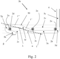
- the aforementioned horizontal rods 2v are welded to the first horizontal rods 2o and are placed both above and below the first horizontal rods 2o to impart strength to the support base 2. Therefore, as shown in Figure 2 , the first horizontal rods 2o of the support base 2 are parallel to the long sides of the base and are sandwiched between two orders of second horizontal rods 2v parallel to the short sides of the support base 2.
- the containment gabion 1 defines an internal volume that is or can be filled with inert material, such containment gabion having for this purpose a top opening through which the internal volume of the containment gabion can be filled with the internal material.
- the connection between the lower end 3a of the vertical walls 3 and the support base 2 is ensured by the provision of hooks 5, namely first hooks 5b or second hooks 5a, which are preferably provided at the lower ends of the vertical rods 4 of each vertical wall 3.
- These hooks 5 may have different shapes depending on the relevant vertical wall.
- connection is conveniently provided by means of a U-shaped second hook 5a, provided at the lower ends of the vertical rods 4, such U-shaped second hook 5a being able to fasten the vertical rods 4 of the vertical wall 3 to the rod of said second order of second horizontal rods 2v of the support base 2 that is closest to the respective vertical rod 4 of the wall to be connected, as shown in Figure 5 .
- the aforementioned fastening system with the U-shaped second hook 5a can be conveniently used also to constrain the vertical walls 3 to each other at the adjacent lateral ends.
- the U-shaped second hooks 5a are provided at the ends of the horizontal rods of the long vertical walls 3c, to fasten each horizontal rod 4 of a long vertical wall 3c to the first vertical rod 6 of each adjacent short vertical wall 3c.
- first hooks 5b with a J-like shape are conveniently used.
- each J-shaped first hook 5b comprises, at the lower end of its respective vertical rod 4 of the long vertical walls 3c:
- the first hook 5b engages the aforementioned first horizontal rod 2b by defining a substantially 90° curve around said first horizontal rod 2b.
- the aforementioned first straight portion 5e is a straight portion and is substantially parallel to the ground support plane identified by the support base 2.
- This first straight portion 5e is useful to impart proper stability to the containment gabion 1 during unloading and assembly, i.e. when no load of inert material is present. Also, the first straight portion 5e facilitates stacking of a plurality of gabions for creating complex structures.
- the aforementioned second portion 5f extends downstream of the first straight portion 5e, to above the third horizontal rod 2d.
- the aforementioned second bending point 5g can hook and anchor the structure of the first hook 5b to hook said third horizontal rod 2d, the subsequent third portion 5h being also useful for this purpose.
- the second bending point 5g encircles the aforementioned third horizontal rod 2d through substantially 180°, whereas the subsequent third portion 5h ensures that this bending point will not be released from the aforementioned third horizontal rod 2d.
- the aforementioned second portion 5f of the first hook 5b comprises two inclined portions f', f" converging in a vertex (50).
- the aforementioned ideal straight line I passing through the opposite ends of the second portion 5f is inclined by an angle ⁇ of 12° to 70°, more preferably an angle of 18° to 40°, with respect to the aforementioned ground support plane identified by the support base 2.
- the aforementioned two portions f' and f" converging in the aforementioned vertex 50 are two straight portions.
- the aforementioned vertex subtends an angle ⁇ of 110° to 170°, more preferably an angle ⁇ of 145° to 165°, for example of 160°.
- the aforementioned second portion 5f of the first hook 5b comprises a curvilinear profile whose convexity faces the interior of the containment gabion.
- the aforementioned second portion 5f of the first hook 5b remains substantially contained in the thickness of the support base 2.
- the aforementioned third portion 5h extends from said second bending point (5g) for a section of 18 mm to 50 mm, more preferably for a section of 20 mm to 45 mm and even more preferably for a section of 25 mm to 30 mm.
- the aforementioned third portion 5h is a straight portion, preferably a straight portion extending in a direction substantially parallel to the aforementioned ideal straight line I passing through the opposite ends of the second portion 5f.
- the aforementioned third straight portion 5h is inclined by an angle ⁇ with respect to the ground support plane identified by said support base 2 which is of 8° to 22°, more preferably by an angle ⁇ of 10° to 18°.
- At least most of the aforementioned third straight portion 5h remains contained in the thickness of the support base 2.
- the second bending point 5g and the third straight portion 5h are designed to increase the safety of the hook 5b to ensure a firmer constraint and impart a higher structural stability to the containment gabion 1 during loading and transport.
- each of the opposite vertical walls 3 of said gabion extending along the two long sides of the support base 2 comprises a plurality of said first hooks 5b whereby the vertical rods 4 of the long vertical walls 3c are fastened to the base 2.
- the containment gabion 1 comprises at least two comb-like hooks 7 comprising a substantially flat quadrangular body 7a extending in a longitudinal direction, and having a top edge 7b and a bottom edge 7c.
- the comb-like hook 7 comprises a plurality of comb teeth 7d, substantially extending the body 7a and bent at least partially into a U shape.
- Each comb-like hook 7 also comprises a plurality of holes 7e formed in the body 7a and longitudinally arranged along such body 7a.
- Each of the two long vertical walls 3c of the containment gabion 1 comprises, as described above, a plurality of horizontal rods 6, including a top horizontal rod 6a differing from the others by being the farthest rod from the support base 2.
- each comb-like hook 7 partially engages the top horizontal rod 6a by the aforementioned U-shaped comb teeth 7d, while the comb-like hook 7 is left free of rotating about the top horizontal bar 6a.
- the containment gabion 1 is lifted by hoist means, not shown, which hook the containment gabion 1 at the holes 7e of the two comb-like hooks 7, the latter assuming thus a position transverse to the support plane.
- the containment gabion 1 Once the containment gabion 1 has been positioned, it is released from the hoist means and the comb-like hooks 7 are rotated to such a position that the body 7a, substantially parallel to the support plane, will rest on the inert material itself or on a closing surface 8, if any.
- these comb-like hooks afford simple and practical transport, and can assume a position that ensures the lack of bulk transverse to the support surface once transport has been completed, thereby allowing a plurality of gabions to be stacked one above the other to form complex structures such as barriers and/or retaining walls.
- parts of the hooks 5 projecting from the lower part of the support plane identified by the support base 2 may be of hindrance as they cause warping or other deformations of the structure of the containment gabion itself before it is filled, which warping and deformation will permanently remain once the structure has been filled with the inert material.
- the improved containment gabion obviates these problems in that the aforementioned second portion (5f) of the first hooks (5b) is not straight, but comprises two inclined portions (f', f") converging in a vertex (50) so as to be more displaced toward the inside of the containment gabion 1, that is, upwards, thereby increasing the space that can be occupied by the third portion 5h which extends as a continuation of the second bending point 5g.
- the end portion of the first hooks 5b i.e. the aforementioned third portion 5h, finds room to be advantageously accommodated in the thickness of the support base in its entirety or for a prevalent part thereof, thus not affecting the coplanarity of the support plane identified by the lower part of the support base 2.
- the improved containment gabion of the present invention is able to ensure stability of the structure during loading, unloading and transport, and can also simplify assembly of the single containment gabion and stacking of a plurality of gabions to form complex monolithic structures.
Landscapes
- Engineering & Computer Science (AREA)
- Civil Engineering (AREA)
- Life Sciences & Earth Sciences (AREA)
- General Life Sciences & Earth Sciences (AREA)
- Mining & Mineral Resources (AREA)
- Paleontology (AREA)
- Environmental & Geological Engineering (AREA)
- General Engineering & Computer Science (AREA)
- Structural Engineering (AREA)
- Pit Excavations, Shoring, Fill Or Stabilisation Of Slopes (AREA)
- Revetment (AREA)
- Micro-Organisms Or Cultivation Processes Thereof (AREA)
- Compounds Of Alkaline-Earth Elements, Aluminum Or Rare-Earth Metals (AREA)
Claims (13)
- Behälter-Metallkasten (1) zum Aufnehmen von Inertstoffen, umfassend einen Hohlkörper aufweisend einen Innenraum, der geeignet ist, Inertstoffe aufzunehmen, wobei:- der Hohlkörper durch eine Mehrzahl von Seitenwänden aufweisend eine Metallgitterstruktur, die eine Stützbasis (2) umfasst, aus welcher Vertikalwänden (3) vorstehen, identifiziert wird;- die Stützbasis (2) eine Bodenstützebene des Metallkastens (1) identifiziert, die eine Netzstruktur umfasst, die durch eine erste Anordnung von ersten Horizontalstäben (2o), die sich parallel zu einer ersten Seite des Behälter-Metallkastens (1) erstrecken und durch eine zweite Anordnung von zweiten Horizontalstäben (2v), die sich orthogonal zu den ersten Horizontalstäben (2o) erstrecken, gebildet wird;- jede Vertikalwand (3) eine Gitterstruktur umfasst, die durch Vertikalstäben (4) und Horizontalstäben (6) gebildet wird, die miteinander verbunden sind, um die oben erwähnte Metallgitterstruktur zu bilden;- jede Vertikalwand (3) an der Stützbasis (2) an einem ihrer unteren Enden (3a) befestigt ist und benachbarte Vertikalwände (3) an den jeweiligen seitlichen Enden (3b),und wobei mindestens eine Vertikalwand (3), die sich parallel zu der ersten Anordnung von ersten Horizontalstäben (2o) erstreckt, mindestens einen Vertikalstab (4) umfasst, der am unteren Ende (3a) der Vertikalwand (3) einen ersten Haken (5b) umfasst, der Folgendes aufweist:- einen Vertikalabschnitt (5c), der sich im Wesentlichen senkrecht zu der Bodenstützebene erstreckt, die durch die Stützbasis (2) gebildet wird;- einen ersten Faltungspunkt (5d), der sich als Verlängerung des Vertikalabschnitts (5c) um einen ersten Horizontalstab (2b) der Stützbasis (2) erstreckt, wobei der erste Horizontalstab (2b) der Horizontalstab der ersten Anordnung der ersten Horizontalstäbe (2o) ist, die dem Vertikalabschnitt (5c) am nächsten liegt;- einen ersten Abschnitt (5e), der sich als Verlängerung des ersten Faltungspunkts (5d) parallel zu und unterhalb der durch die Stützbasis (2) identifizierten Bodenstützebene erstreckt, bis er einen zweiten Horizontalstab (2c) der ersten Anordnung der ersten Horizontalstäbe (2o) der Stützbasis (2) überragt, wobei der zweite Horizontalstab (2c) mehr von dem Vertikalabschnitt (5c) als der erste Horizontalstab (2b) beabstandet ist;- einen zweiten Abschnitt (5f), der sich zwischen gegenüberliegenden Enden als Verlängerung des ersten Abschnitts (5e) mit einer Entwicklungsrichtung erstreckt, die in Bezug auf die durch die Stützbasis (2) identifizierte Bodenstützebene geneigt ist, so dass er sich in Richtung der Innenseite des Behälter-Metallkastens (1) bis zu einem dritten Horizontalstab (2d) der ersten Anordnung der ersten Horizontalstäbe (2o) der Stützbasis (2) erstreckt, wobei der dritte Horizontalstab (2d) mehr von dem Vertikalabschnitt (5c) als der zweite Horizontalstab (2c) beabstandet ist;- einen zweiten Faltungspunkt (5g), der sich als Verlängerung des zweiten Abschnitts (5f) erstreckt, um den dritten Horizontalstab (2d) zuzuhaken, und- einen dritten Abschnitt (5h), der sich als Verlängerung des zweiten Faltungspunkts (5g) erstreckt und der eine einfallende Entwicklungsrichtung in Bezug auf die durch die Stützbasis (2) identifizierte Bodenstützebene aufweist,dadurch gekennzeichnet, dass:d er zweite Abschnitt (5f) des ersten Hakens (5b) einen Zwischenabschnitt aufweist, der in Bezug auf eine ideale gerade Linie (I), die sich durch die gegenüberliegenden Enden des zweiten Abschnitts (5f) erstreckt, mehr zu der Innenseite des Behälter-Metallkastens (1) verschoben ist.
- Behälter-Metallkasten (1) nach Anspruch 1, wobei der zweite Abschnitt (5f) des ersten Hakens (5b) zwei geneigte Abschnitte (f', f") umfasst, die in einem Scheitelpunkt (50) zusammenlaufen, wobei der Scheitelpunkt (50) mehr zu der Innenseite des Behälter-Metallkastens (1) als die ideale gerade Linie (I), die sich durch die gegenüberliegenden Enden des zweiten Abschnitts (5f) erstreckt, verschoben ist.
- Behälter-Metallkasten (1) nach Anspruch 2, wobei der zweite Abschnitt (5f) des ersten Hakens (5b) durch zwei geneigte Abschnitte (f', f"), die in dem Scheitelpunkt (50) zusammenlaufen, identifiziert wird, wobei die beiden geneigten Abschnitte vorzugsweise zwei gerade Abschnitte sind.
- Behälter-Metallkasten (1) nach Anspruch 3, wobei die beiden geneigten Abschnitte (f', f"), die in einem Scheitelpunkt (50) zusammenlaufen, um einen Winkel λ zwischen 110° und 170°, vorzugsweise um einen Winkel λ zwischen 145° und 165°, geneigt sind.
- Behälter-Metallkasten (1) nach Anspruch 1, wobei der zweite Abschnitt (5f) des ersten Hakens (5b) einen gekrümmten Profilabschnitt mit einer der Innenseite des Behälter-Metallkastens (1) zugewandten konvexen Form aufweist.
- Behälter-Metallkasten (1) nach einem der Ansprüche 1 bis 5, wobei der zweite Abschnitt (5f) des ersten Hakens (5b) im Wesentlichen in der Dicke der Stützbasis (2) enthalten bleibt.
- Behälter-Metallkasten (1) nach einem der Ansprüche 1 bis 6, wobei die sich durch die gegenüberliegenden Enden des zweiten Abschnitts (5f) erstreckende ideale gerade Linie (I) um einen Winkel α zwischen 12° und 70°, vorzugsweise um einen Winkel zwischen 18° und 40°, in Bezug auf die durch die Stützbasis (2) identifizierte Bodenstützebene geneigt ist.
- Behälter-Metallkasten(1) nach einem der Ansprüche 1 bis 7, wobei der dritte Abschnitt (5h) ein gerader Abschnitt ist, vorzugsweise ein gerader Abschnitt, der sich von dem zweiten Faltungspunkt (5g) um einen Schnitt zwischen 18 mm und 50 mm, besonders bevorzugt um einen Schnitt zwischen 20 mm und 45 mm erstreckt.
- Behälter-Metallkasten (1) nach einem der Ansprüche 1 bis 8, wobei der erste Abschnitt (5e) des Hakens (5b) ein gerader Abschnitt ist.
- Behälter-Metallkasten (1) nach einem der Ansprüche 1 bis 9, wobei:- der zweite Horizontalstab (2c) an den ersten Horizontalstab (2b) angrenzt und/oder- der dritte Horizontalstab (2d) an den zweiten Horizontalstab (2c) angrenzt.
- Behälter-Metallkasten (1) nach einem der Ansprüche 1 bis 10, wobei:- die Stützbasis (2) eine längere Seite als die anderen Seiten aufweist und wobei- sich die erste Anordnung der ersten Horizontalstäbe (2o) parallel zu einer ersten Seite des Behälter-Metallkastens (1) parallel zu der längeren Seite der Stützbasis (2) erstreckt.
- Behälter-Metallkasten (1) nach Anspruch 11, wobei jede der gegenüberliegenden Vertikalwände (3) des Behälter-Metallkastens (1), die sich parallel zu einer längeren Seite der Stützbasis (2) erstrecken, eine Mehrzahl der ersten Haken (5b) umfasst.
- Behälter-Metallkasten (1) nach einem der Ansprüche 1 bis 12, umfassend eine Mehrzahl von zweiten Haken (5a), die vorzugsweise U-förmig ausgebildet sind, um das untere Ende mindestens einer Vertikalwand (3d), die sich parallel zu der zweiten Anordnung der zweiten Horizontalstäbe (2v) erstreckt, mit dem Horizontalstab (2v) der zweiten Anordnung der zweiten Horizontalstäbe (2v), der der Wand (3) am nächsten liegt, zu verbinden.
Applications Claiming Priority (2)
| Application Number | Priority Date | Filing Date | Title |
|---|---|---|---|
| IT102020000029318A IT202000029318A1 (it) | 2020-12-01 | 2020-12-01 | Gabbione di contenimento perfezionato per il contenimento ed il trasporto di materiale inerte |
| PCT/IB2021/061071 WO2022118173A1 (en) | 2020-12-01 | 2021-11-29 | An improved containment gabion for containing and carrying inert material |
Publications (3)
| Publication Number | Publication Date |
|---|---|
| EP4256137A1 EP4256137A1 (de) | 2023-10-11 |
| EP4256137B1 true EP4256137B1 (de) | 2024-11-27 |
| EP4256137C0 EP4256137C0 (de) | 2024-11-27 |
Family
ID=74759281
Family Applications (1)
| Application Number | Title | Priority Date | Filing Date |
|---|---|---|---|
| EP21836626.8A Active EP4256137B1 (de) | 2020-12-01 | 2021-11-29 | Verbessertes sicherheitsbehältergabion zum aufbewahren und transportieren von inertem material |
Country Status (6)
| Country | Link |
|---|---|
| US (1) | US20240093457A1 (de) |
| EP (1) | EP4256137B1 (de) |
| CA (1) | CA3200196A1 (de) |
| ES (1) | ES3002721T3 (de) |
| IT (1) | IT202000029318A1 (de) |
| WO (1) | WO2022118173A1 (de) |
Family Cites Families (5)
| Publication number | Priority date | Publication date | Assignee | Title |
|---|---|---|---|---|
| US5860551A (en) * | 1997-04-07 | 1999-01-19 | Knott, Sr.; James M. | Gabion container |
| DE20015651U1 (de) | 2000-09-08 | 2000-11-30 | Weber, Rainer, 54578 Walsdorf | Steinkorb |
| DE20120822U1 (de) * | 2001-12-21 | 2002-03-21 | Rothfuss, Thomas, 71735 Eberdingen | Gittermatte, insbesondere für Gabionenkörbe |
| US7033118B2 (en) * | 2004-06-23 | 2006-04-25 | Hilfiker Pipe Company | Compressible welded wire retaining wall and rock face for earthen formations |
| MA40429A (fr) * | 2015-03-27 | 2017-12-12 | Metallurgica Ledrense Soc Cooperativa | Gabion |
-
2020
- 2020-12-01 IT IT102020000029318A patent/IT202000029318A1/it unknown
-
2021
- 2021-11-29 ES ES21836626T patent/ES3002721T3/es active Active
- 2021-11-29 CA CA3200196A patent/CA3200196A1/en active Pending
- 2021-11-29 WO PCT/IB2021/061071 patent/WO2022118173A1/en not_active Ceased
- 2021-11-29 US US18/255,202 patent/US20240093457A1/en active Pending
- 2021-11-29 EP EP21836626.8A patent/EP4256137B1/de active Active
Also Published As
| Publication number | Publication date |
|---|---|
| ES3002721T3 (en) | 2025-03-07 |
| EP4256137A1 (de) | 2023-10-11 |
| CA3200196A1 (en) | 2022-06-09 |
| US20240093457A1 (en) | 2024-03-21 |
| IT202000029318A1 (it) | 2022-06-01 |
| WO2022118173A1 (en) | 2022-06-09 |
| EP4256137C0 (de) | 2024-11-27 |
Similar Documents
| Publication | Publication Date | Title |
|---|---|---|
| CN101443518B (zh) | 石笼 | |
| US7001110B2 (en) | Precast concrete retaining wall | |
| US7722296B1 (en) | Retaining wall soil reinforcing connector and method | |
| EA009235B1 (ru) | Высокопрочная опалубка для бетонных стен | |
| WO1999023325A1 (en) | Cellular stirrups and ties for structural members | |
| JP2009255985A (ja) | 結束部材を備えたコンテナ | |
| US20090285639A1 (en) | Soil reinforcing retaining wall anchor | |
| JP5023371B2 (ja) | 石詰籠 | |
| EP0334265A1 (de) | Tank-Container | |
| US20240093457A1 (en) | An improved containment gabion for containing and carrying inert material | |
| EP3073017B1 (de) | Gabione | |
| EP2581499B1 (de) | Gabione | |
| EP2241679B1 (de) | Gabione mit einer geschlossenen Struktur | |
| KR200406178Y1 (ko) | 콘크리트 파일의 두부 보강용 철근캡 | |
| KR200422860Y1 (ko) | 옹벽용 개비온 | |
| KR101821990B1 (ko) | 갈퀴형 보강재를 구비한 내진보강용 철근조립체, 및 이를 이용한 철근콘크리트 기둥의 제작방법 | |
| JP7610324B2 (ja) | 布団篭の本体パネル及び布団篭 | |
| US20150132070A1 (en) | Mechanically stabilized earth system and method | |
| EP4491833B1 (de) | H-förmiges betonfertigteil für den bau von lagerhallen | |
| CN216003953U (zh) | 垃圾仓 | |
| KR102395444B1 (ko) | 스페이서가 선택적으로 결합된 보강바 스트럭쳐 시스템 | |
| RU1784027C (ru) | Резервуар дл транспортировки и хранени жидкостей или мелкозернистого сыпучего материала | |
| JP6885770B2 (ja) | 金物 | |
| JP2018031257A (ja) | 構造物構築用セット、構造物を構築する方法 | |
| JP2022055434A (ja) | ふとん籠及びふとん籠の吊り上げ方法 |
Legal Events
| Date | Code | Title | Description |
|---|---|---|---|
| STAA | Information on the status of an ep patent application or granted ep patent |
Free format text: STATUS: UNKNOWN |
|
| STAA | Information on the status of an ep patent application or granted ep patent |
Free format text: STATUS: THE INTERNATIONAL PUBLICATION HAS BEEN MADE |
|
| PUAI | Public reference made under article 153(3) epc to a published international application that has entered the european phase |
Free format text: ORIGINAL CODE: 0009012 |
|
| STAA | Information on the status of an ep patent application or granted ep patent |
Free format text: STATUS: REQUEST FOR EXAMINATION WAS MADE |
|
| 17P | Request for examination filed |
Effective date: 20230622 |
|
| AK | Designated contracting states |
Kind code of ref document: A1 Designated state(s): AL AT BE BG CH CY CZ DE DK EE ES FI FR GB GR HR HU IE IS IT LI LT LU LV MC MK MT NL NO PL PT RO RS SE SI SK SM TR |
|
| RAV | Requested validation state of the european patent: fee paid |
Extension state: TN Effective date: 20230622 Extension state: MD Effective date: 20230622 Extension state: MA Effective date: 20230622 |
|
| GRAP | Despatch of communication of intention to grant a patent |
Free format text: ORIGINAL CODE: EPIDOSNIGR1 |
|
| STAA | Information on the status of an ep patent application or granted ep patent |
Free format text: STATUS: GRANT OF PATENT IS INTENDED |
|
| INTG | Intention to grant announced |
Effective date: 20240718 |
|
| GRAS | Grant fee paid |
Free format text: ORIGINAL CODE: EPIDOSNIGR3 |
|
| GRAA | (expected) grant |
Free format text: ORIGINAL CODE: 0009210 |
|
| STAA | Information on the status of an ep patent application or granted ep patent |
Free format text: STATUS: THE PATENT HAS BEEN GRANTED |
|
| AK | Designated contracting states |
Kind code of ref document: B1 Designated state(s): AL AT BE BG CH CY CZ DE DK EE ES FI FR GB GR HR HU IE IS IT LI LT LU LV MC MK MT NL NO PL PT RO RS SE SI SK SM TR |
|
| REG | Reference to a national code |
Ref country code: GB Ref legal event code: FG4D |
|
| REG | Reference to a national code |
Ref country code: CH Ref legal event code: EP |
|
| REG | Reference to a national code |
Ref country code: DE Ref legal event code: R096 Ref document number: 602021022603 Country of ref document: DE |
|
| REG | Reference to a national code |
Ref country code: IE Ref legal event code: FG4D |
|
| U01 | Request for unitary effect filed |
Effective date: 20241218 |
|
| U07 | Unitary effect registered |
Designated state(s): AT BE BG DE DK EE FI FR IT LT LU LV MT NL PT RO SE SI Effective date: 20250102 |
|
| U20 | Renewal fee for the european patent with unitary effect paid |
Year of fee payment: 4 Effective date: 20241220 |
|
| REG | Reference to a national code |
Ref country code: ES Ref legal event code: FG2A Ref document number: 3002721 Country of ref document: ES Kind code of ref document: T3 Effective date: 20250307 |
|
| PG25 | Lapsed in a contracting state [announced via postgrant information from national office to epo] |
Ref country code: IS Free format text: LAPSE BECAUSE OF FAILURE TO SUBMIT A TRANSLATION OF THE DESCRIPTION OR TO PAY THE FEE WITHIN THE PRESCRIBED TIME-LIMIT Effective date: 20250327 Ref country code: HR Free format text: LAPSE BECAUSE OF FAILURE TO SUBMIT A TRANSLATION OF THE DESCRIPTION OR TO PAY THE FEE WITHIN THE PRESCRIBED TIME-LIMIT Effective date: 20241127 |
|
| PG25 | Lapsed in a contracting state [announced via postgrant information from national office to epo] |
Ref country code: NO Free format text: LAPSE BECAUSE OF FAILURE TO SUBMIT A TRANSLATION OF THE DESCRIPTION OR TO PAY THE FEE WITHIN THE PRESCRIBED TIME-LIMIT Effective date: 20250227 |
|
| PG25 | Lapsed in a contracting state [announced via postgrant information from national office to epo] |
Ref country code: GR Free format text: LAPSE BECAUSE OF FAILURE TO SUBMIT A TRANSLATION OF THE DESCRIPTION OR TO PAY THE FEE WITHIN THE PRESCRIBED TIME-LIMIT Effective date: 20250228 |
|
| PG25 | Lapsed in a contracting state [announced via postgrant information from national office to epo] |
Ref country code: PL Free format text: LAPSE BECAUSE OF FAILURE TO SUBMIT A TRANSLATION OF THE DESCRIPTION OR TO PAY THE FEE WITHIN THE PRESCRIBED TIME-LIMIT Effective date: 20241127 |
|
| PG25 | Lapsed in a contracting state [announced via postgrant information from national office to epo] |
Ref country code: RS Free format text: LAPSE BECAUSE OF FAILURE TO SUBMIT A TRANSLATION OF THE DESCRIPTION OR TO PAY THE FEE WITHIN THE PRESCRIBED TIME-LIMIT Effective date: 20250227 |
|
| PG25 | Lapsed in a contracting state [announced via postgrant information from national office to epo] |
Ref country code: SM Free format text: LAPSE BECAUSE OF FAILURE TO SUBMIT A TRANSLATION OF THE DESCRIPTION OR TO PAY THE FEE WITHIN THE PRESCRIBED TIME-LIMIT Effective date: 20241127 |
|
| VS25 | Lapsed in a validation state [announced via postgrant information from nat. office to epo] |
Ref country code: MD Free format text: LAPSE BECAUSE OF FAILURE TO SUBMIT A TRANSLATION OF THE DESCRIPTION OR TO PAY THE FEE WITHIN THE PRESCRIBED TIME-LIMIT Effective date: 20241127 |
|
| PG25 | Lapsed in a contracting state [announced via postgrant information from national office to epo] |
Ref country code: SK Free format text: LAPSE BECAUSE OF FAILURE TO SUBMIT A TRANSLATION OF THE DESCRIPTION OR TO PAY THE FEE WITHIN THE PRESCRIBED TIME-LIMIT Effective date: 20241127 |
|
| PG25 | Lapsed in a contracting state [announced via postgrant information from national office to epo] |
Ref country code: CZ Free format text: LAPSE BECAUSE OF FAILURE TO SUBMIT A TRANSLATION OF THE DESCRIPTION OR TO PAY THE FEE WITHIN THE PRESCRIBED TIME-LIMIT Effective date: 20241127 |
|
| PG25 | Lapsed in a contracting state [announced via postgrant information from national office to epo] |
Ref country code: MC Free format text: LAPSE BECAUSE OF FAILURE TO SUBMIT A TRANSLATION OF THE DESCRIPTION OR TO PAY THE FEE WITHIN THE PRESCRIBED TIME-LIMIT Effective date: 20241127 |
|
| PLBE | No opposition filed within time limit |
Free format text: ORIGINAL CODE: 0009261 |
|
| STAA | Information on the status of an ep patent application or granted ep patent |
Free format text: STATUS: NO OPPOSITION FILED WITHIN TIME LIMIT |
|
| REG | Reference to a national code |
Ref country code: CH Ref legal event code: L10 Free format text: ST27 STATUS EVENT CODE: U-0-0-L10-L00 (AS PROVIDED BY THE NATIONAL OFFICE) Effective date: 20251008 |
|
| 26N | No opposition filed |
Effective date: 20250828 |
|
| REG | Reference to a national code |
Ref country code: CH Ref legal event code: U11 Free format text: ST27 STATUS EVENT CODE: U-0-0-U10-U11 (AS PROVIDED BY THE NATIONAL OFFICE) Effective date: 20251201 |
|
| U20 | Renewal fee for the european patent with unitary effect paid |
Year of fee payment: 5 Effective date: 20251127 |
|
| PGFP | Annual fee paid to national office [announced via postgrant information from national office to epo] |
Ref country code: GB Payment date: 20251125 Year of fee payment: 5 |
|
| PGFP | Annual fee paid to national office [announced via postgrant information from national office to epo] |
Ref country code: CH Payment date: 20251201 Year of fee payment: 5 |
|
| PGFP | Annual fee paid to national office [announced via postgrant information from national office to epo] |
Ref country code: IE Payment date: 20251118 Year of fee payment: 5 |
|
| PGFP | Annual fee paid to national office [announced via postgrant information from national office to epo] |
Ref country code: ES Payment date: 20251209 Year of fee payment: 5 |
|
| VS25 | Lapsed in a validation state [announced via postgrant information from nat. office to epo] |
Ref country code: MA Free format text: FAILURE TO ELECT DOMICILE IN THE NATIONAL COUNTRY Effective date: 20250228 |
|
| PG25 | Lapsed in a contracting state [announced via postgrant information from national office to epo] |
Ref country code: HU Free format text: LAPSE BECAUSE OF FAILURE TO SUBMIT A TRANSLATION OF THE DESCRIPTION OR TO PAY THE FEE WITHIN THE PRESCRIBED TIME-LIMIT; INVALID AB INITIO Effective date: 20211129 |
|
| PG25 | Lapsed in a contracting state [announced via postgrant information from national office to epo] |
Ref country code: CY Free format text: LAPSE BECAUSE OF FAILURE TO SUBMIT A TRANSLATION OF THE DESCRIPTION OR TO PAY THE FEE WITHIN THE PRESCRIBED TIME-LIMIT; INVALID AB INITIO Effective date: 20211129 |
|
| VS25 | Lapsed in a validation state [announced via postgrant information from nat. office to epo] |
Ref country code: MA Free format text: LAPSE BECAUSE OF FAILURE TO SUBMIT A TRANSLATION OF THE DESCRIPTION OR TO PAY THE FEE WITHIN THE PRESCRIBED TIME-LIMIT Effective date: 20241127 |