EP4255779B1 - Verfahren zum beladen eines vierrädrigen fahrzeugs und zugehöriger transportförderer - Google Patents
Verfahren zum beladen eines vierrädrigen fahrzeugs und zugehöriger transportförderer Download PDFInfo
- Publication number
- EP4255779B1 EP4255779B1 EP21830717.1A EP21830717A EP4255779B1 EP 4255779 B1 EP4255779 B1 EP 4255779B1 EP 21830717 A EP21830717 A EP 21830717A EP 4255779 B1 EP4255779 B1 EP 4255779B1
- Authority
- EP
- European Patent Office
- Prior art keywords
- vehicle
- transporter
- arms
- conveyor
- loading
- Prior art date
- Legal status (The legal status is an assumption and is not a legal conclusion. Google has not performed a legal analysis and makes no representation as to the accuracy of the status listed.)
- Active
Links
Images

Classifications
-
- B—PERFORMING OPERATIONS; TRANSPORTING
- B65—CONVEYING; PACKING; STORING; HANDLING THIN OR FILAMENTARY MATERIAL
- B65G—TRANSPORT OR STORAGE DEVICES, e.g. CONVEYORS FOR LOADING OR TIPPING, SHOP CONVEYOR SYSTEMS OR PNEUMATIC TUBE CONVEYORS
- B65G67/00—Loading or unloading vehicles
- B65G67/02—Loading or unloading land vehicles
-
- E—FIXED CONSTRUCTIONS
- E04—BUILDING
- E04H—BUILDINGS OR LIKE STRUCTURES FOR PARTICULAR PURPOSES; SWIMMING OR SPLASH BATHS OR POOLS; MASTS; FENCING; TENTS OR CANOPIES, IN GENERAL
- E04H6/00—Buildings for parking cars, rolling-stock, aircraft, vessels or like vehicles, e.g. garages
- E04H6/08—Garages for many vehicles
- E04H6/12—Garages for many vehicles with mechanical means for shifting or lifting vehicles
- E04H6/30—Garages for many vehicles with mechanical means for shifting or lifting vehicles with means for transport in horizontal direction only
- E04H6/305—Garages for many vehicles with mechanical means for shifting or lifting vehicles with means for transport in horizontal direction only using car-gripping transfer means
-
- B—PERFORMING OPERATIONS; TRANSPORTING
- B60—VEHICLES IN GENERAL
- B60S—SERVICING, CLEANING, REPAIRING, SUPPORTING, LIFTING, OR MANOEUVRING OF VEHICLES, NOT OTHERWISE PROVIDED FOR
- B60S13/00—Vehicle-manoeuvring devices separate from the vehicle
-
- B—PERFORMING OPERATIONS; TRANSPORTING
- B66—HOISTING; LIFTING; HAULING
- B66F—HOISTING, LIFTING, HAULING OR PUSHING, NOT OTHERWISE PROVIDED FOR, e.g. DEVICES WHICH APPLY A LIFTING OR PUSHING FORCE DIRECTLY TO THE SURFACE OF A LOAD
- B66F7/00—Lifting frames, e.g. for lifting vehicles; Platform lifts
- B66F7/24—Lifting frames, e.g. for lifting vehicles; Platform lifts for raising or lowering vehicles by their own power
- B66F7/243—Ramps
-
- B—PERFORMING OPERATIONS; TRANSPORTING
- B66—HOISTING; LIFTING; HAULING
- B66F—HOISTING, LIFTING, HAULING OR PUSHING, NOT OTHERWISE PROVIDED FOR, e.g. DEVICES WHICH APPLY A LIFTING OR PUSHING FORCE DIRECTLY TO THE SURFACE OF A LOAD
- B66F9/00—Devices for lifting or lowering bulky or heavy goods for loading or unloading purposes
- B66F9/06—Devices for lifting or lowering bulky or heavy goods for loading or unloading purposes movable, with their loads, on wheels or the like, e.g. fork-lift trucks
- B66F9/063—Automatically guided
-
- B—PERFORMING OPERATIONS; TRANSPORTING
- B66—HOISTING; LIFTING; HAULING
- B66F—HOISTING, LIFTING, HAULING OR PUSHING, NOT OTHERWISE PROVIDED FOR, e.g. DEVICES WHICH APPLY A LIFTING OR PUSHING FORCE DIRECTLY TO THE SURFACE OF A LOAD
- B66F9/00—Devices for lifting or lowering bulky or heavy goods for loading or unloading purposes
- B66F9/06—Devices for lifting or lowering bulky or heavy goods for loading or unloading purposes movable, with their loads, on wheels or the like, e.g. fork-lift trucks
- B66F9/075—Constructional features or details
- B66F9/12—Platforms; Forks; Other load supporting or gripping members
- B66F9/18—Load gripping or retaining means
Definitions
- the present invention relates to the field of electric handling vehicles, in particular conveyors for transporting or moving four-wheeled vehicles.
- DE 20 2004 018058 U1 discloses a method similar to the preamble of claim 1, and a conveyor similar to the conveyor of the preamble of claim 7.
- the step of stopping the movement of the conveyor and generating a signal representative of the state of mobility of said vehicle is carried out as a function of the temporal variation of a detected force.
- the predetermined force is for example a force corresponding to an increase of at least 30% of the force detected during contact of a wedging arm with a tread.
- the loading of the vehicle is interrupted.
- the step of stopping the movement of the conveyor and generating a signal representative of the state of mobility of said vehicle is carried out as a function of the temporal variation of a detected distance.
- the loading of the vehicle is interrupted.
- the present invention relates to a transport conveyor for loading four-wheeled vehicles, comprising a telescopic chassis comprising wedging arms arranged to be positioned on either side of the tread of a wheel of the vehicle to be loaded, characterized in that it comprises means for detecting the presence or clamping of the vehicle wheel comprising at least one sensor and a presence or clamping detection calculator collecting the data from the at least one sensor and generating a signal representative of the state of mobility of said vehicle as a function of said data.
- the transport conveyor is of the type comprising a telescopic chassis in a longitudinal direction, the chassis comprising a main beam and a secondary beam movable relative to the main beam, each beam comprising a side member extending transversely and on either side of said beam, each side member having a pair of arms articulated to said side member, each arm being connected to one end of a side member.
- the arms are movable between a position in which they allow said chassis to move under the vehicle, and a position in which they come into contact with the treads of said wheels.
- Each arm is articulated about a pivot axis to allow movement between a position perpendicular to the longitudinal axis of the chassis and a folded position to occupy a width less than the distance between the inner flanks of the wheels of the vehicle.
- the length of the assembly comprising the pair of arms and a side member is at least equal to the track of the vehicle to be loaded or moved.
- the height of the chassis, including the elements it supports, and for the part intended to be engaged under the vehicle to be transported, is determined to be less than the ground clearance of the vehicle.
- said pair of articulated arms is transversely movable.
- the presence or clamping detection means comprise means for detecting the position of a wheel.
- the means for detecting the position of a wheel are laser, ultrasonic or radar telemetric sensors.
- the presence or clamping detection means are contact detection means.
- the contact detection means comprise at least one spring.
- these comprise means for detecting a force.
- the means for detecting a force are force sensors of the strain gauge or pressure probe type, or by the interpretation of an indirect signal, such as, for example, the increase in the electrical consumption of the clamping cylinder motor.
- the presence or clamping detection means are arranged on the wedging arms.
- the clamping detection means are arranged on the pivot axes of the wedging arms.
- the means for detecting a force comprise a torque sensor and/or a sensor measuring the intensity of the electric actuator(s) actuating the wedging arm(s).
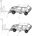
- FIG. 1 represents a perspective view of a first embodiment of a conveyor.
- the conveyor comprises a chassis comprising a main beam 2 and a secondary beam 3 slidably mounted inside the main beam 2.
- a cylinder or linear actuator (not shown), for example a worm screw, makes it possible to actuate the secondary beam 3 relative to the main beam 2 in order to obtain a telescopic chassis.
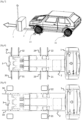
- the spacing between each pair consisting of a fixed arm and a retractable arm facing each other 21, 23 and 22, 24 is determined so that they come into contact with the front and rear sides of the vehicle tire and pinch said tire in order to ensure the lifting of the vehicle.
- the fixed arms 21, 22 have an inclined ramp 28, 29.
- the length L of the side members 25, 35, measured between the pivot axes of the retractable front arms 23, 24 and the retractable rear arms 31, 32 is less than Vmin-Lmin, where: Vmin designates the usual and minimum track of a car, typically 1600 millimeters, Lmin designates the usual width of the tire of a car, typically 220 millimeters.
- the length L of the side members is therefore typically less than 1400 millimeters, and preferably of the order of 1200 millimeters.
- the length of the fixed arms 21, 22, the retractable front arms 23, 24 and the retractable rear arms 31, 32 is determined to correspond to half the width lmax corresponding to the width between the external flanks of the wheels of a large car. dimension minus the length of the spar 25, 35, typically 500 millimeters for each of the arms.
- the conveyor can thus be positioned in the axis of the vehicle in order to allow the conveyor chassis to pass under the vehicle with the wedging arms 23, 24, 31, 32 in the folded position, oriented substantially longitudinally, until the ramps 28, 29 of the fixed arms 21, 22 come into abutment against the front wheels of the vehicle.
- the retractable chock arms 31, 32 are then moved to a transverse position.
- the secondary chassis beam is actuated forward to accommodate the wheelbase of the car to be loaded and bring the retractable chock arms 31, 32 into contact with the rear treads of the vehicle wheels.
- the support arms 23, 24 are deployed to raise the vehicles onto the fixed arms 21, 22.
- the conveyor has four ultrasonic telemetry sensors 41 to 44 delivering signals depending on the distance from the vehicle bumper.
- the conveyor comprises vehicle wheel clamping detection means comprising at least one sensor and a clamping detection calculator collecting data from the at least one sensor and generating a signal representative of the mobility state of said vehicle as a function of said data.
- the clamping detection means comprise two force sensors 46, 47 for detecting and validating the vehicle grip, and two short-range scanning laser telemetric sensors 26, 27 for detecting wheels and obstacles.
- the four sensors are arranged on the front side member 25.
- the wheel presence detection means comprise two short-range scanning laser telemetry sensors 48, 49 for detecting wheels and obstacles.
- the two laser telemetry sensors 48, 49 are arranged on the rear spar 35.
- the chassis formed by beams 2, 3 and side members 25, 35 has casters or rollers to allow rolling on the ground.
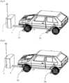
- FIGS. 2 to 7 represent schematic views of the vehicle and conveyor at successive loading stages.
- the conveyor comes to position itself in front of the car which is parked on a deposit space and in a manner substantially aligned with respect to said vehicle.
- the movable support arms 23, 24, 31, 32, 33, 34 are in the folded or retracted position.
- Short range laser rangefinders 48, 49 detect the first set of wheels of the vehicle so as to position the conveyor chassis relative to the vehicle to be loaded.
- the rear chock arms 31, 32 are retracted into a transverse position.
- the chock arms could hold the vehicle if the parking brake were not locked.
- the conveyor then advances until the front fixed arms 21, 22 come into contact with the front wheels (see figure 5 ).
- the force sensors 46, 47 and the short-range laser rangefinders 26, 27 indicate that the wheels are in contact.
- the secondary beam deploys until the rear wheels of the vehicle are detected by the short-range laser rangefinders 48, 49.
- the conveyor moves along the longitudinal axis of the conveyor so that the force sensors 46, 47 detect an increase in force compared to the force detected when contact with the wheels is detected. As soon as this force is detected, the movement of the conveyor is stopped.
- the application detection computer indicates that the parking brake is properly locked and the loading procedure continues.
- the application detection computer indicates that the parking brake is not locked and the loading procedure is interrupted.
- the conveyor then adjusts ( figure 6 ) the length of the secondary beam so that the rear support arms 31, 32 touch the rear wheels. As soon as the retractable front arms 23, 24 clamp the front wheels the vehicle rises.
- the force sensors 48, 49 validate that the vehicle is mounted on the fixed support arms 21, 22, the conveyor is moved automatically to take the vehicle to the target location, see figure 7 .
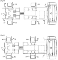
- each clamping pair consisting of a rear arm and a distal arm facing each other 31, 33 and 32, 34 is determined so that they come into contact with the front and rear sides of the vehicle tire and pinch said tire in order to ensure the lifting of the vehicle.
- the retractable distal arms 34, 33 are in the retracted locking position, they block the movement of the vehicle relative to the conveyor.
- the conveyor is positioned under a car and in a substantially parallel manner, the car being represented by four squares illustrating the tires of said car.
- the movable wedging arms 23, 24, 31, 32, 33, 34 are in the folded or retracted position.
- the short-range laser rangefinders placed on the secondary beam 3 detect the front wheels of the vehicle so as to position the conveyor chassis relative to the vehicle to be loaded, before the short-range laser rangefinders placed on the main beam 2 subsequently detect the front wheels of the vehicle and until the front fixed arms 21, 22 come into contact with the front wheels (see figure 9 ).
- Force sensors and short-range laser rangefinders, placed on the main beam 2 indicate that the wheels are in contact.
- the secondary beam 3 deploys until the rear wheels of the vehicle are detected by the short-range laser rangefinders by said beam 3.
- the rear support arms 31, 32 are retracted into a transverse position.
- the conveyor moves along the longitudinal axis of the conveyor so that the force sensors detect an increase in force compared to the force detected when contact with the wheels is detected. As soon as this force is detected, the movement of the conveyor is stopped.
- the application detection computer indicates that the parking brake is properly locked and the loading procedure continues.
- the application detection computer indicates that the parking brake is not locked and the loading procedure is interrupted.
- the conveyor then adjusts the length of the secondary beam.
- the front chock arms 23, 24 and the distal chock arms 33, 34 are retracted to clamp the wheels of the vehicle before lifting said vehicle.
- the force sensors validate that the vehicle is mounted on the chock arms.
Landscapes
- Engineering & Computer Science (AREA)
- Structural Engineering (AREA)
- Mechanical Engineering (AREA)
- Transportation (AREA)
- Architecture (AREA)
- Civil Engineering (AREA)
- Life Sciences & Earth Sciences (AREA)
- Geology (AREA)
- Aviation & Aerospace Engineering (AREA)
- Automobile Manufacture Line, Endless Track Vehicle, Trailer (AREA)
- Handcart (AREA)
- Vehicle Cleaning, Maintenance, Repair, Refitting, And Outriggers (AREA)
Claims (10)
- Verfahren zum Beladen eines vierrädrigen Fahrzeugs mittels eines Transportförderers (90), umfassend Feststellarme (21, 22, 23, 24, 31, 32, 33, 34), die zum Einnehmen einer Position auf beiden Seiten der Lauffläche eines Rades des zu beladenden Fahrzeugs (100) angeordnet sind, und Mittel (46, 47, 48, 49) zum Erkennen eines Vorhandenseins oder Einklemmen eines Rades, das Verfahren umfassend die folgenden Schritte:- einen Schritt zum Bewegen des Förderers (90), bis ein Feststellarm (21, 22, 23, 24, 31, 32, 33, 34) mit einer Lauffläche eines Reifens in Kontakt kommt,- einen Schritt zum Bewegen des Förderers entlang der Längsachse des Förderers um eine zuvor bestimmte Distanz oder bis zu dem Erkennen einer zuvor bestimmten Kraft,
dadurch gekennzeichnet, dass das Verfahren ferner umfasst:- einen Schritt zum Anhalten des Bewegens des Förderers und zum Erzeugen eines Signals, das den Verschiebbarkeitszustand des Fahrzeugs (100) darstellt: verschiebbar oder feststehend. - Verfahren nach Anspruch 1, im Laufe dessen der Schritt zum Anhalten des Bewegens des Förderers und zum Erzeugen eines Signals, das den Verschiebbarkeitszustand des Fahrzeugs darstellt, in Abhängigkeit von der zeitlichen Änderung einer erkannten Kraft ausgeführt wird.
- Verfahren nach dem vorstehenden Anspruch, im Laufe dessen das Beladen des Fahrzeugs im Falle der Aufhebung der Kraft, die nach dem Schritt zum Anhalten des Bewegens des Förderers erkannt wird, unterbrochen wird.
- Verfahren nach Anspruch 1, im Laufe dessen der Schritt zum Anhalten des Bewegens des Förderers und zum Erzeugen eines Signals, das den Verschiebbarkeitszustand des Fahrzeugs darstellt, in Abhängigkeit von der zeitlichen Änderung einer erkannten Distanz ausgeführt wird.
- Verfahren nach dem vorstehenden Anspruch, im Laufe dessen das Beladen des Fahrzeugs im Falle der Vergrößerung der Distanz, die nach dem Schritt zum Anhalten des Bewegens des Förderers erkannt wird, unterbrochen wird.
- Verfahren nach Anspruch 3 oder 5, im Laufe dessen die Übermittlung einer Nachricht im Falle eines Unterbrechens des Beladens vorgesehen ist.
- Elektrischer Transportförderer (90) zum Beladen von vierrädrigen Fahrzeugen, umfassend ein ausziehbares Fahrgestell (2, 3), umfassend Feststellarme (21, 22, 23, 24, 31, 32, 33, 34), die zum Einnehmen einer Position auf beiden Seiten der Lauffläche eines Rades des zu beladenden Fahrzeugs (100) angeordnet sind,
dadurch gekennzeichnet, dass er Mittel zum Erkennen des Vorhandenseins oder Einklemmen eines Fahrzeugrads umfasst, umfassend mindestens einen Sensor (46, 47, 48, 49) und einen Rechner zum Erkennen des Vorhandenseins oder Einklemmen, der die Daten des mindestens einen Sensors sammelt und ein Signal, das den Verschiebbarkeitszustand des Fahrzeugs in Abhängigkeit der Daten darstellt, erzeugt. - Förderer nach Anspruch 7, im Laufe dessen die Mittel zum Erkennen des Vorhandenseins oder Einklemmen Mittel zum Erkennen der Position eines Rads umfassen.
- Förderer nach Anspruch 7, im Laufe dessen die Mittel zum Erkennen des Vorhandenseins oder Einklemmen Krafterkennungsmittel umfassen.
- Förderer nach einem der Ansprüche 7 bis 9, im Laufe dessen die Mittel zum Erkennen des Vorhandenseins oder Einklemmen an den Feststellarmen eingerichtet sind.
Applications Claiming Priority (2)
| Application Number | Priority Date | Filing Date | Title |
|---|---|---|---|
| FR2012512A FR3116779B1 (fr) | 2020-12-02 | 2020-12-02 | Procédé de chargement d’un véhicule à quatre roues et convoyeur de transport associé |
| PCT/FR2021/052144 WO2022117945A1 (fr) | 2020-12-02 | 2021-11-30 | Procédé de chargement d'un véhicule à quatre roues et convoyeur de transport associé |
Publications (3)
| Publication Number | Publication Date |
|---|---|
| EP4255779A1 EP4255779A1 (de) | 2023-10-11 |
| EP4255779C0 EP4255779C0 (de) | 2024-10-09 |
| EP4255779B1 true EP4255779B1 (de) | 2024-10-09 |
Family
ID=74206059
Family Applications (1)
| Application Number | Title | Priority Date | Filing Date |
|---|---|---|---|
| EP21830717.1A Active EP4255779B1 (de) | 2020-12-02 | 2021-11-30 | Verfahren zum beladen eines vierrädrigen fahrzeugs und zugehöriger transportförderer |
Country Status (7)
| Country | Link |
|---|---|
| US (1) | US20240102307A1 (de) |
| EP (1) | EP4255779B1 (de) |
| JP (1) | JP7646836B2 (de) |
| CN (1) | CN116529185A (de) |
| ES (1) | ES3005835T3 (de) |
| FR (1) | FR3116779B1 (de) |
| WO (1) | WO2022117945A1 (de) |
Families Citing this family (2)
| Publication number | Priority date | Publication date | Assignee | Title |
|---|---|---|---|---|
| JP7613289B2 (ja) * | 2021-06-23 | 2025-01-15 | トヨタ自動車株式会社 | 車両運搬装置 |
| US12151730B2 (en) * | 2023-01-11 | 2024-11-26 | Marlin Bedford | Vehicle cart assembly |
Family Cites Families (6)
| Publication number | Priority date | Publication date | Assignee | Title |
|---|---|---|---|---|
| JPH07180391A (ja) * | 1993-12-21 | 1995-07-18 | Mitsubishi Heavy Ind Ltd | パーキングブレーキ着脱検出装置 |
| JPH08246697A (ja) * | 1995-01-13 | 1996-09-24 | Mitsubishi Heavy Ind Ltd | 車両のサイドブレーキ作動状態検出装置 |
| DE202004018058U1 (de) * | 2004-11-20 | 2005-01-13 | WAP Wöhr Automatikparksysteme GmbH & Co.KG | Aufnahmevorrichtung für ein Fahrzeug |
| FR3036349B1 (fr) * | 2015-05-20 | 2018-03-16 | Stanley Robotics | Convoyeurs mobiles destines au deplacement d'un vehicule a 4 roues. |
| JP6994236B2 (ja) * | 2017-10-26 | 2022-01-14 | 新明工業株式会社 | 車両のリフト搬送台車、縦列無人走行台車、車両縦列駐車システムおよび車両縦列駐車方法 |
| FR3090540B1 (fr) * | 2018-12-20 | 2020-12-18 | Stanley Robotics | Convoyeur pour le déplacement de véhicules à quatre roues |
-
2020
- 2020-12-02 FR FR2012512A patent/FR3116779B1/fr active Active
-
2021
- 2021-11-30 EP EP21830717.1A patent/EP4255779B1/de active Active
- 2021-11-30 JP JP2023531011A patent/JP7646836B2/ja active Active
- 2021-11-30 CN CN202180080033.XA patent/CN116529185A/zh active Pending
- 2021-11-30 WO PCT/FR2021/052144 patent/WO2022117945A1/fr not_active Ceased
- 2021-11-30 ES ES21830717T patent/ES3005835T3/es active Active
- 2021-11-30 US US18/254,580 patent/US20240102307A1/en active Pending
Also Published As
| Publication number | Publication date |
|---|---|
| JP7646836B2 (ja) | 2025-03-17 |
| WO2022117945A1 (fr) | 2022-06-09 |
| EP4255779C0 (de) | 2024-10-09 |
| FR3116779A1 (fr) | 2022-06-03 |
| JP2024502538A (ja) | 2024-01-22 |
| US20240102307A1 (en) | 2024-03-28 |
| CN116529185A (zh) | 2023-08-01 |
| EP4255779A1 (de) | 2023-10-11 |
| FR3116779B1 (fr) | 2022-12-02 |
| ES3005835T3 (en) | 2025-03-17 |
Similar Documents
| Publication | Publication Date | Title |
|---|---|---|
| EP3297876B1 (de) | Bewegliche förderer zum bewegen eines vierrädrigen fahrzeugs | |
| EP4255779B1 (de) | Verfahren zum beladen eines vierrädrigen fahrzeugs und zugehöriger transportförderer | |
| EP2537684B1 (de) | Halbachse und Fahrzeug, das mit mindestens einer solchen Halbachse ausgestattet ist | |
| EP2236445B1 (de) | Vorrichtung zum Halten eines LKW, Verfahren und Verwendung derselben | |
| EP2825428B1 (de) | Fahrzeugpierradblockanordnung und -installation | |
| EP3962844B1 (de) | Vorrichtung zum blockieren eines fahrzeugs vor einer ladebrücke | |
| EP0384850B1 (de) | Selbsttätige Anhaltevorrichtung für Kraftfahrzeuge, z.B. für einen Lastwagen an einer Laderampe | |
| EP2089302B1 (de) | Schuh zum stillstand eines rades und motorisierte stillstandanordnung | |
| EP3191342B1 (de) | Transportfahrzeug mit erweiterter längsstruktur für eine motorbetriebene handhabungsvorrichtung | |
| FR3039528A1 (fr) | Dispositif pour l'immobilisation d'un vehicule tel qu'une remorque devant un quai de chargement | |
| EP4119415B1 (de) | Sattelkupplungsanordnung | |
| FR3107893A1 (fr) | Dispositif de blocage d'un véhicule routier devant un emplacement de chargement-déchargement | |
| FR2948235A1 (fr) | Systeme d'antenne comprenant un brin actif et un cable a denudage limite | |
| EP4281636B1 (de) | Automatisches parksystem und zugehöriges verfahren zum parken von kraftfahrzeugen | |
| FR2901515A1 (fr) | Vehicule de transport pourvu de moyens d'acces pour personnes a mobilite reduite | |
| FR3008309A1 (fr) | Vehicule automobile a acces facilite par l'arriere du vehicule | |
| EP3645446B1 (de) | Hubwagen mit ladestopp | |
| EP2767818B1 (de) | Diagnosesystem des strukturellen Zustands einer Rolleinheit eines Rollwagens auf einer Schiene, das punktuelle Sende- und Empfangsantennen umfasst | |
| FR3036337A1 (fr) | Dispositif d'abaissement de la caisse d'un vehicule comportant un moyen de detection de la position haute |
Legal Events
| Date | Code | Title | Description |
|---|---|---|---|
| STAA | Information on the status of an ep patent application or granted ep patent |
Free format text: STATUS: UNKNOWN |
|
| STAA | Information on the status of an ep patent application or granted ep patent |
Free format text: STATUS: THE INTERNATIONAL PUBLICATION HAS BEEN MADE |
|
| PUAI | Public reference made under article 153(3) epc to a published international application that has entered the european phase |
Free format text: ORIGINAL CODE: 0009012 |
|
| STAA | Information on the status of an ep patent application or granted ep patent |
Free format text: STATUS: REQUEST FOR EXAMINATION WAS MADE |
|
| 17P | Request for examination filed |
Effective date: 20230620 |
|
| AK | Designated contracting states |
Kind code of ref document: A1 Designated state(s): AL AT BE BG CH CY CZ DE DK EE ES FI FR GB GR HR HU IE IS IT LI LT LU LV MC MK MT NL NO PL PT RO RS SE SI SK SM TR |
|
| DAV | Request for validation of the european patent (deleted) | ||
| DAX | Request for extension of the european patent (deleted) | ||
| GRAP | Despatch of communication of intention to grant a patent |
Free format text: ORIGINAL CODE: EPIDOSNIGR1 |
|
| STAA | Information on the status of an ep patent application or granted ep patent |
Free format text: STATUS: GRANT OF PATENT IS INTENDED |
|
| INTG | Intention to grant announced |
Effective date: 20240507 |
|
| GRAS | Grant fee paid |
Free format text: ORIGINAL CODE: EPIDOSNIGR3 |
|
| GRAA | (expected) grant |
Free format text: ORIGINAL CODE: 0009210 |
|
| STAA | Information on the status of an ep patent application or granted ep patent |
Free format text: STATUS: THE PATENT HAS BEEN GRANTED |
|
| AK | Designated contracting states |
Kind code of ref document: B1 Designated state(s): AL AT BE BG CH CY CZ DE DK EE ES FI FR GB GR HR HU IE IS IT LI LT LU LV MC MK MT NL NO PL PT RO RS SE SI SK SM TR |
|
| REG | Reference to a national code |
Ref country code: CH Ref legal event code: EP |
|
| REG | Reference to a national code |
Ref country code: DE Ref legal event code: R096 Ref document number: 602021020121 Country of ref document: DE |
|
| REG | Reference to a national code |
Ref country code: IE Ref legal event code: FG4D Free format text: LANGUAGE OF EP DOCUMENT: FRENCH |
|
| U01 | Request for unitary effect filed |
Effective date: 20241028 |
|
| U07 | Unitary effect registered |
Designated state(s): AT BE BG DE DK EE FI FR IT LT LU LV MT NL PT RO SE SI Effective date: 20241108 |
|
| U20 | Renewal fee for the european patent with unitary effect paid |
Year of fee payment: 4 Effective date: 20241227 |
|
| REG | Reference to a national code |
Ref country code: ES Ref legal event code: FG2A Ref document number: 3005835 Country of ref document: ES Kind code of ref document: T3 Effective date: 20250317 |
|
| PG25 | Lapsed in a contracting state [announced via postgrant information from national office to epo] |
Ref country code: IS Free format text: LAPSE BECAUSE OF FAILURE TO SUBMIT A TRANSLATION OF THE DESCRIPTION OR TO PAY THE FEE WITHIN THE PRESCRIBED TIME-LIMIT Effective date: 20250209 Ref country code: HR Free format text: LAPSE BECAUSE OF FAILURE TO SUBMIT A TRANSLATION OF THE DESCRIPTION OR TO PAY THE FEE WITHIN THE PRESCRIBED TIME-LIMIT Effective date: 20241009 |
|
| PGFP | Annual fee paid to national office [announced via postgrant information from national office to epo] |
Ref country code: ES Payment date: 20250114 Year of fee payment: 4 |
|
| PG25 | Lapsed in a contracting state [announced via postgrant information from national office to epo] |
Ref country code: NO Free format text: LAPSE BECAUSE OF FAILURE TO SUBMIT A TRANSLATION OF THE DESCRIPTION OR TO PAY THE FEE WITHIN THE PRESCRIBED TIME-LIMIT Effective date: 20250109 |
|
| PG25 | Lapsed in a contracting state [announced via postgrant information from national office to epo] |
Ref country code: GR Free format text: LAPSE BECAUSE OF FAILURE TO SUBMIT A TRANSLATION OF THE DESCRIPTION OR TO PAY THE FEE WITHIN THE PRESCRIBED TIME-LIMIT Effective date: 20250110 |
|
| PG25 | Lapsed in a contracting state [announced via postgrant information from national office to epo] |
Ref country code: PL Free format text: LAPSE BECAUSE OF FAILURE TO SUBMIT A TRANSLATION OF THE DESCRIPTION OR TO PAY THE FEE WITHIN THE PRESCRIBED TIME-LIMIT Effective date: 20241009 |
|
| PGFP | Annual fee paid to national office [announced via postgrant information from national office to epo] |
Ref country code: CZ Payment date: 20250114 Year of fee payment: 4 |
|
| PG25 | Lapsed in a contracting state [announced via postgrant information from national office to epo] |
Ref country code: RS Free format text: LAPSE BECAUSE OF FAILURE TO SUBMIT A TRANSLATION OF THE DESCRIPTION OR TO PAY THE FEE WITHIN THE PRESCRIBED TIME-LIMIT Effective date: 20250109 |
|
| REG | Reference to a national code |
Ref country code: CH Ref legal event code: PL |
|
| PG25 | Lapsed in a contracting state [announced via postgrant information from national office to epo] |
Ref country code: SM Free format text: LAPSE BECAUSE OF FAILURE TO SUBMIT A TRANSLATION OF THE DESCRIPTION OR TO PAY THE FEE WITHIN THE PRESCRIBED TIME-LIMIT Effective date: 20241009 |
|
| PG25 | Lapsed in a contracting state [announced via postgrant information from national office to epo] |
Ref country code: MC Free format text: LAPSE BECAUSE OF FAILURE TO SUBMIT A TRANSLATION OF THE DESCRIPTION OR TO PAY THE FEE WITHIN THE PRESCRIBED TIME-LIMIT Effective date: 20241009 |
|
| REG | Reference to a national code |
Ref country code: CH Ref legal event code: PL |
|
| PG25 | Lapsed in a contracting state [announced via postgrant information from national office to epo] |
Ref country code: CH Free format text: LAPSE BECAUSE OF NON-PAYMENT OF DUE FEES Effective date: 20241130 |
|
| PG25 | Lapsed in a contracting state [announced via postgrant information from national office to epo] |
Ref country code: SK Free format text: LAPSE BECAUSE OF FAILURE TO SUBMIT A TRANSLATION OF THE DESCRIPTION OR TO PAY THE FEE WITHIN THE PRESCRIBED TIME-LIMIT Effective date: 20241009 |
|
| PLBE | No opposition filed within time limit |
Free format text: ORIGINAL CODE: 0009261 |
|
| STAA | Information on the status of an ep patent application or granted ep patent |
Free format text: STATUS: NO OPPOSITION FILED WITHIN TIME LIMIT |
|
| 26N | No opposition filed |
Effective date: 20250710 |
|
| PG25 | Lapsed in a contracting state [announced via postgrant information from national office to epo] |
Ref country code: IE Free format text: LAPSE BECAUSE OF NON-PAYMENT OF DUE FEES Effective date: 20241130 |