EP4255669B1 - System zur überprüfung der integrität eines werkzeugs - Google Patents
System zur überprüfung der integrität eines werkzeugs Download PDFInfo
- Publication number
- EP4255669B1 EP4255669B1 EP21830953.2A EP21830953A EP4255669B1 EP 4255669 B1 EP4255669 B1 EP 4255669B1 EP 21830953 A EP21830953 A EP 21830953A EP 4255669 B1 EP4255669 B1 EP 4255669B1
- Authority
- EP
- European Patent Office
- Prior art keywords
- tool
- checking system
- inductor
- checking
- contact
- Prior art date
- Legal status (The legal status is an assumption and is not a legal conclusion. Google has not performed a legal analysis and makes no representation as to the accuracy of the status listed.)
- Active
Links
Images


Classifications
-
- B—PERFORMING OPERATIONS; TRANSPORTING
- B23—MACHINE TOOLS; METAL-WORKING NOT OTHERWISE PROVIDED FOR
- B23Q—DETAILS, COMPONENTS, OR ACCESSORIES FOR MACHINE TOOLS, e.g. ARRANGEMENTS FOR COPYING OR CONTROLLING; MACHINE TOOLS IN GENERAL CHARACTERISED BY THE CONSTRUCTION OF PARTICULAR DETAILS OR COMPONENTS; COMBINATIONS OR ASSOCIATIONS OF METAL-WORKING MACHINES, NOT DIRECTED TO A PARTICULAR RESULT
- B23Q17/00—Arrangements for observing, indicating or measuring on machine tools
- B23Q17/09—Arrangements for observing, indicating or measuring on machine tools for indicating or measuring cutting pressure or for determining cutting-tool condition, e.g. cutting ability, load on tool
- B23Q17/0952—Arrangements for observing, indicating or measuring on machine tools for indicating or measuring cutting pressure or for determining cutting-tool condition, e.g. cutting ability, load on tool during machining
- B23Q17/0957—Detection of tool breakage
-
- B—PERFORMING OPERATIONS; TRANSPORTING
- B23—MACHINE TOOLS; METAL-WORKING NOT OTHERWISE PROVIDED FOR
- B23Q—DETAILS, COMPONENTS, OR ACCESSORIES FOR MACHINE TOOLS, e.g. ARRANGEMENTS FOR COPYING OR CONTROLLING; MACHINE TOOLS IN GENERAL CHARACTERISED BY THE CONSTRUCTION OF PARTICULAR DETAILS OR COMPONENTS; COMBINATIONS OR ASSOCIATIONS OF METAL-WORKING MACHINES, NOT DIRECTED TO A PARTICULAR RESULT
- B23Q17/00—Arrangements for observing, indicating or measuring on machine tools
- B23Q17/22—Arrangements for observing, indicating or measuring on machine tools for indicating or measuring existing or desired position of tool or work
- B23Q17/2233—Arrangements for observing, indicating or measuring on machine tools for indicating or measuring existing or desired position of tool or work for adjusting the tool relative to the workpiece
- B23Q17/2241—Detection of contact between tool and workpiece
Definitions
- the present invention relates to a system for checking the integrity of a metal tool present in a machine tool, and finds a particularly advantageous application in the check of rotating tools coupled to the spindles of machine tools such as drilling and milling machines for processing metal workpieces.
- Inductive-type systems which comprise circuit elements typically connected near the spindle of the machine tool, for example a milling machine or a drilling machine, and which detect variations caused in these circuit elements by the contact between the metal tool and the - also metallic - processed workpiece. The circumstances in which this contact is detected or not provide information on the integrity of the tool.
- Patent US-A-4203691 shows and describes a system of this type, similar to the known system of figure 1.
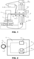
- Figure 1 schematically shows a machine tool, for example a drilling machine, for machining a metal workpiece 2, with a support structure 1 which comprises a spindle 6, a tool holder with a shaft 5 rotating around a rotation axis X, coupled to the spindle 6 by means of bearings, and a rotating tool 3 aligned along the axis X and connected to the spindle, the spindle 6 and the workpiece 2 being mutually movable along the direction defined by the rotation axis X of the shaft 5.
- a machine tool for example a drilling machine, for machining a metal workpiece 2
- a support structure 1 which comprises a spindle 6, a tool holder with a shaft 5 rotating around a rotation axis X, coupled to the spindle 6 by means of bearings, and a rotating tool 3 aligned along the axis X and connected to the spindle, the
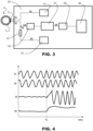
- An inductor 4 comprising a winding wound on a portion of an annular core made of ferromagnetic material arranged near the tool holder, around the rotation axis X, in particular disposed externally and coaxially to the rotating shaft 5, is part of a detection circuit or primary circuit which also includes elements of a module 8 ( figure 2 ).
- the module 8 includes a power source, in particular an alternating current generator 11, a resistor 15 and a voltage or voltage variation detector 17 across the resistor 15.
- a secondary circuit C defined by a loop which includes the tool 3, the rotating shaft 5, the support structure 1 and the metal workpiece 2 is closed.
- the closure of the secondary circuit C causes a variation of the inductance parameters and a consequent variation of the voltage across the resistor 15, the latter being detected by the detector 17. If the tool 3 is broken, the contact does not occur, or at least it does not occur when it should do, and consequently no variation of the inductance parameters is detected.
- the module 8 is connected to a control unit 10 which controls the movements of the different parts of the machine tool, for example a PLC programmable unit, which checks whether, in correspondence with the mutual position between tool and workpiece at which the machining should start, the contact is detected or not, that is whether or not a detection signal has been received by the detection circuit comprising the inductor 4. If not, an alarm signal is generated, the processing is stopped and other known procedures are initiated, such as the automatic replacement of the damaged tool with an intact one taken from a suitable repository.
- a control unit 10 which controls the movements of the different parts of the machine tool, for example a PLC programmable unit, which checks whether, in correspondence with the mutual position between tool and workpiece at which the machining should start, the contact is detected or not, that is whether or not a detection signal has been received by the detection circuit comprising the inductor 4. If not, an alarm signal is generated, the processing is stopped and other known procedures are initiated, such as the automatic replacement of the damaged tool with an intact one taken from a suitable repository.
- a problem that may occur in known systems is the difficulty of properly detecting the contact between tool and workpiece in case that this contact is not maintained during the whole processing, but occurs in limited periods of time, only. This is the case, for example, of machining processes in which the metal chip breaks causing a loss of contact for intervals of time that cannot always be predictable and of milling operations, in which the rotating tool intermittently touches the workpiece that is working.
- the tool has cutting edges that, during a rotation of 360°, touch the piece for rotation angles of limited amplitude, for example of 5° or less.
- the contact time between the tool and the workpiece can be less than 5 microseconds.
- the known detection circuits and systems do not allow to detect the inductance variations caused by the short contacts between the cutting edges and the workpiece, and as a consequence are not very reliable. This is especially true in case of very small tools, with diameter values of about one millimeter, where the contacts are very light and of very short duration.
- Another problem of the system of figure 1 is the difficulty in detecting the contact between the tool and the workpiece, in particular the voltage variation across the resistance of the detector, for example due to the relatively high resistance of the secondary circuit C when the shaft 5 rotates.
- Such resistance can vary and increase considerably by virtue of the dynamic behaviour of the bearings and/or of the presence of lubricants.
- This problem can also arise if in the path that defines the secondary circuit there are elements of low or zero electrical conductivity, for example when the bearings are made of ceramic material.
- the purpose of the present invention is to provide a system for checking the integrity of the tool that is reliable and overcomes the problems of the known systems, allowing to obtain reliable results even in those cases in which the tool, or the machine tool where the tool is used, have mechanical, electrical or application features that make impossible or of uncertain outcome the checking with known systems.
- a system for checking the integrity of a tool comprises a detection circuit which generates a detection signal indicative of the contact between the tool and the metal piece machined on the machine tool, and a control unit connected to the detection circuit.
- the detection circuit comprises an inductor with an annular core arranged near a tool holder of the machine tool and windings wound on the annular core.
- the detection circuit has a half-bridge configuration with two resistive branches powered by AC excitation voltages that are substantially 90° out of phase with each other and respectively comprising the inductor and a reference resistor which preferably has a resistance substantially equal to the impedance of the inductor, and a detection branch with a conversion unit, typically an RMS converter, and a processing unit for generating and transmitting the detection signal to the control unit.
- a conversion unit typically an RMS converter
- the primary circuit comprises the inductor 4, with a core 7 of ferromagnetic material (for example ferrite) having an annular, for example toroidal, shape and windings 9 which are connected to terminals t1 and t2 of a power supply and processing module 18 connected to these terminals t1 and t2.
- ferromagnetic material for example ferrite
- the module 18 includes
- a node t3 leads to the detection branch and also to a first resistive branch or excitation branch - comprising the generator 21 and, through the terminals t1 and t2, the windings 9 of the inductor 4 - and a second resistive branch or excitation branch with the generator 22 and the resistor 25.
- the excitation and detection branches thus define a half-bridge configuration.
- the secondary circuit In the absence of contact between the tool and the workpiece, the secondary circuit is open.
- the voltage S3 at the node t3 has a negligible amplitude. Consequently, the output signal from the filter 26 (where unwanted disturbances and frequencies are eliminated or attenuated) and the "averaged" signal S4, at the output of the RMS converter 27, have a substantially constant trend, without significant variations in amplitude ( figure 4 , trend before the instant T1).
- the tool 3 touches the workpiece 2, the loop C comprising the tool 3, the workpiece 2, the tool holder with the rotating shaft 5, and the support structure 1 of the machine tool comprising the spindle 6, closes.
- this loop C that is in the secondary circuit linked to the inductor 4
- a current is induced which in turn causes a variation in the current which passes through the windings 9 of the inductor 4 and, consequently, in the voltage S3 in correspondence of the node t3. Thanks to the half-bridge configuration of the circuit, the signal S3 can have a high crest factor.
- the RMS converter 27 typically has a very low average time constant, for example about 30 microseconds. This makes it possible to obtain a very rapid response to the variations of the signal output from the filter 26 which in turn reflects substantially in real time the variations of the signal S3 at the node t3 of the half-bridge circuit, variations which, on the basis of the foregoing above, can be very short and fast.
- the signal S4 at the output of the RMS converter 27 is an always positive signal, cleaned of the electrical noise present in the signal at the output of the filter 26. In this way it is possible to capture very limited duration variations of the signal S3 indicative of short contacts between the tool 3 and the piece 2, as occurs for example in milling operations or in processes in which the metal chip breaks causing loss of contact for time intervals that are generally unpredictable.
- the signal S4 is converted into a digital signal in the converter 28 and the digital signal obtained is read by the microprocessor 30 where it is processed in a known way, for example it is compared with a threshold value, the exceeding of which indicates that the contact has occurred, with the consequent generation of a detection signal.
- the detection signal is transmitted to the control unit 10 to confirm the correct presence of the operating tool 3. If the tool 3 is broken, the loop C does not close and no signal is sent to the control unit 10. If the microprocessor 30 of the module 18 fails to receive the signal of the contact in correspondence with a mutual position between spindle 6 and metal workpiece 2 in which machining should begin, the control unit 10 stops the movements of the machine tool and possibly starts the automatic tool replacement operations which occur in a manner known per se and not described here.
- the microprocessor 30 can carry out further processing before transmitting to the control unit 10 the detection signal indicating the presence of the tool 3. For example, in the case of check during a milling operation, the microprocessor 30 can check whether the tool is present and intact by recording the succession of contacts between the cutting edges and the workpiece and comparing the duration and frequency of these contacts with theoretical or predetermined values relating to the specific machining (type of tool used, rotation speed, cutting parameters such as removal and advancement, etc.).
- the half-bridge configuration of the secondary circuit which includes the inductor 4 and the use of a suitable conversion unit such as the RMS converter 27 allow to obtain a high signal/noise ratio and a considerable sensitivity in detecting variations in electrical characteristics of the same circuit.
- the signal S3 present at the terminal t3 of the half-bridge configuration can have a high crest factor, i.e. it is able to follow fast variations of the electrical characteristics caused in the inductor 4 by the contact between the tool 3 and the metallic workpiece 2, and the RMS converter 27 is in turn capable of detecting such fast variations and providing a signal S4 with a high signal-to-noise ratio.
- the inductor 4 can be arranged in a different position with respect to what is shown in figure 1 , for example it can be placed, always near the tool holder or around the shaft 5, but inside the spindle 6, for example in an intermediate position between the bearings.
- the presence of the filter 26 is not essential, even if it is advantageous for eliminating or attenuating unwanted frequencies which would interfere in a negative way with the proper processing of the useful signals.
- a different embodiment of the present invention may comprise a conversion unit other than the RMS converter 27, for example a peak-to-peak detector, even though the RMS converter provides better results, since, in addition to providing a (further) filter, it provides an always positive signal that, as already mentioned, is particularly quick to reflect the variations in input.
- a conversion unit other than the RMS converter 27 for example a peak-to-peak detector
- the description above refers to the check of a rotating tool.
- the system according to the present invention can also be applied to the check of a tool that does not rotate, for example a tool connected to the turret of a lathe that can move with respect to a rotating piece being machined, for example along a direction corresponding to the axis X of the figures.
- Figure 5 shows an alternative solution to that of figure 1 .
- a secondary circuit C' does not close through the bearings of the spindle 6 which allow the rotation of the shaft 5, but through a special contact mechanism, schematized with reference 37, which creates a (direct) electrical connection between the shaft 5 and a part of the support structure 1 of the machine tool, for example the spindle 6.
- This allows to avoid problems due to the reduced electrical conductivity of the bearings during the rotation of the shaft 5 and to use the system according to the present invention in the case of zero electrical conductivity, for example in the case of bearings made of ceramic material.
- the contact mechanism includes a sliding element, or sliding shoe 40 which comes into direct contact with the rotating shaft 5.
- the sliding shoe 40 may have particular characteristics of shape and material.
- the sliding shoe 40 is made of a conductive and low oxidation material, such as stainless steel or bronze, or a combination of the two, and guarantees good electrical conductivity and wear resistance.
- Other materials can be used for making the sliding shoe 40, for example graphite and silver-graphite.
- the sliding shoe 40 is rigidly connected to the support structure 1 and comprises at least one elastically yielding portion.
- the sliding shoe 40 has a central body 41 rigidly connected to the support structure 1 and two limbs 42 and 43 connected substantially symmetrically to the central body 41 by means of elastically yielding portions or zones 42' and 43' and featuring free ends intended to remain in contact with the shaft 5, in particular at two points of a cross section H of the shaft 5, while the latter rotates around the axis X.
- the sliding shoe 40 preferably comprises a folded piece, made for example of stainless steel, which defines the central body 41, the limbs 42 and 43, and, in correspondence with the folds, the elastically yielding zones 42' and 43'.
- the sliding shoe 40 comprises two blocks or pads 44 and 45, for example in bronze, which define the free ends of the limbs 42 and 43 in contact with the rotating shaft 5.
- the sliding shoe 40 can also be provided a lightening of material, as shown in figure 7 to increase the elastic compliance of the zones 42' and 43'.
- the sliding shoe 40 is connected to the support structure 1 in an adjustable way, for example as illustrated in figure 6 which shows a connection assembly of the sliding shoe 40 to the support structure 1, in particular to the spindle 6, with an adjustable bracket 46 integral with the sliding shoe 40 and a reference bracket 48 (partially shown also in figure 9 ), the adjustable bracket 46 and the reference bracket 48 being connected to each other by means of adjustment elements with a coupling 47 including screws in slots.
- the connection assembly also comprises elements for fixing the reference bracket 48 to the support structure, for example screws 49 with a conical profile head (visible in figure 9 ) and other adjustment elements with a spacer 50 interposed between the reference bracket 48 and the support structure 1 in correspondence with the fixing by means of the screws 49.
- the thickness of the spacer 50 is chosen to determine the desired contact force between the sliding shoe 40 and the shaft 5.
- the final part of the adjustment procedure involves inserting a working spacer 50 of greater (rather than less) thickness than that of the calibration spacer 50' to obtain the desired contact force.
- the sliding shoe 40 is arranged between the shaft 5 and the annular core 7 of the inductor 4.
- the assembly and adjustment operations of the contact mechanism are generally carried out before inserting the inductor 4.
- the particular symmetrical structure of the sliding shoe 40 and the adjustable fixing to the support structure 1 of the machine tool (for example to the spindle 6) guarantee an effective electrical connection between the spindle 5 and the support structure 1 regardless of the rotation speed of the shaft 5 and the direction of rotation.
- the sliding shoe 40 can have a folded piece with a particularly small thickness (for example 0.2 mm). In this case, it may not be necessary to provide for the possibility of adjusting the position and the fastening of the sliding shoe 40 to the support structure 1, since the characteristics of compliance of the sliding shoe 40 itself, in particular of the folded piece that defines the central body 41 and the limbs 42, 43, are sufficient to ensure the correct contact, stable but with not excessive force, between the free ends of the limbs 42 and 43 (in the illustrated example bearing the pads 44, 45) and the rotating shaft 5 and therefore the effective electrical connection between the shaft 5 and the support structure 1.
- a particularly small thickness for example 0.2 mm
- Another aspect of the invention concerns the structure of the core of the inductor 4.
- the inductor 4 comprises a core 7 of ferromagnetic material (for example ferrite) having an annular, for example toroidal, shape and windings 9, with a certain number of coils of copper wire, wound around a portion of the annular core 7.
- ferromagnetic material for example ferrite
- the inductor 4 also comprises a shell 12, partially visible in figures 6 and 9 , which houses the core 7 and the windings 9.
- the shell 12 is generally made of non-magnetic stainless steel and allows the inductor 4 to be fixed to the spindle 6 or to another part of the support structure 1 of the machine tool, arranged in any case coaxially to the axis X of the rotating shaft 5.
- the fixing is carried out in a per se known way, for example by means of screws as can be seen only partially in figure 9 , and is not described in detail for reasons of simplicity.
- the inductor 4 is made in one piece, and in particular the annular core 7 is in one piece and the shell 12 is in one piece.
- the annular core 7 in one piece of material has the homogeneity properties which guarantee the correct behaviour of the inductor 4 within the system.
- the installation of the inductor 4 in the machine tool is complex, and it is particularly complex - or impossible at all - to apply the checking system to already existing and completely assembled machine tools, an application that requires to mount the inductor 4 on the shaft 5 in a machine with certain dimensions and unavoidable mechanical limitations of the access to the various components.
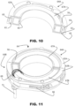
- Figure 11 shows an inductor 64 in which the annular core is made of two portions in ferromagnetic material which have open ends and which are joined at these ends.
- the inductor 64 is used in a checking system according to the present invention, a system which also includes the features already described with reference to figure 1 .
- the inductor 64 comprises two mutually connected half-rings 64A and 64B, each comprising in turn a semi-annular portion in ferromagnetic material, typically ferrite, 67A and 67B and a substantially C-shaped half-shell 62A and 62B.
- Windings are wound on the ferrite semi-annular portion in ferrite of one of the half-rings, in particular on the portion 67B, and are connected to electric wires which come out of the half-ring 64B inside the cable 71.
- Four reference pins 63 are fixed to the ends of the half-shells and cooperate with holes 61 present at the ends of the other half-shell.
- each half-shell 62A and 62B have each a reference pin 63 and a hole 61 but different configurations are possible (for example: all four pins 63 at the ends of one of the two half-shells 62A or 62B and the four holes 61 at the ends of the other; or a pair of pins 63 and one of holes 61 at the two ends of each half-shell 62A or 62B; etc.).
- the pins 63 and the holes 61 represent mechanical references which can be made in different ways, with suitable and per se known elements and/or surfaces, configured to align the ends of the half-rings 64A and 64B.
- the half-shells 62A and 62B are closed in the upper part (with reference to the orientation of figures 10 and 11 ) by suitable shaped elements 60, generally in plastic, which are partially visible in figure 9 but omitted for reasons of clarity in figures 10 and 11 .
- the installation of the inductor 64 on the machine tool takes place by arranging the two half-rings 64A and 64B in a suitable position, around the shaft 5 of the spindle 6, with their respective ends facing each other, positioned by means of the reference pins 63 and the respective holes 61, and fastened to each other, for example by means of screws or other fastening devices.
- these fastening devices comprise a metal collar 66 closed and fastened by a screw, the metal collar 66 having the particularity of uniformly distributing the load over the entire external surface of the half-shells 62A and 62B, making the joint stable and insensitive to shocks and vibrations to which the spindle 6 is subject.
- Each of the semi-annular portions of ferrite 67A and 67B is housed with clearance in the respective half-shell 62A and 62B so that, before carrying out the installation, the respective ends, featuring a flat surface, slightly protrude from the free ends of the half-shells 62A and 62B.
- a resin 70 with good elastic features is present inside each half-shell 62A and 62B, between the semi-annular portions of ferrite 67A and 67B and the internal walls of the half-shells 62A and 62B.
- the elasticity of the resin 70 in addition to allowing the aforementioned sliding, also applies a constant thrust between the two semi-annular portions of ferrite 67A, 67B, a fundamental condition for the proper functioning of the system and its reliability over time.
- the gaskets 65 close the space between the ends of the half-shells 62A and 62B and prevent the entry of dust or other foreign bodies which, infiltrating between the end surfaces of the semi-annular portions of ferrite 67A and 67B, could alter and jeopardize the correct electromagnetic behaviour inductor 64.
- a method of mounting the inductor 64 on a machine tool, in particular around the rotating shaft 5 of the spindle 6 of a machine tool provides for fixing one of the half-shells 62A, 62B to the support structure 1, for example fixing the half-shell 62B to the spindle 6 with screws, as shown in figure 9 , and proceed as described above, that is:
Landscapes
- Engineering & Computer Science (AREA)
- Mechanical Engineering (AREA)
- Machine Tool Sensing Apparatuses (AREA)
- Measurement Of Length, Angles, Or The Like Using Electric Or Magnetic Means (AREA)
Claims (14)
- Prüfsystem zur Überprüfung der Integrität eines Werkzeugs (3) während der Bearbeitung eines Metallstücks (2) auf einer Werkzeugmaschine, die eine Tragstruktur (1, 6) und einen Werkzeughalter (5) umfasst, der das Werkzeug (3) trägt, wobei das Prüfsystem umfasst:- eine Detektionsschaltung (4, 8; 18; 64), die dazu ausgelegt ist, ein Detektionssignal zu erzeugen, das den Kontakt zwischen dem Werkzeug (3) und dem Metallstück (2) anzeigt, mit mindestens einer Leistungsquelle (11; 21, 22) und einem Induktor (4; 64), der einen ringförmigen Kern (7; 67A, 67B), der am Werkzeughalter (5) angeordnet ist, und Wicklungen (9; 69) umfasst, die um den ringförmigen Kern (7; 67A, 67B) gewickelt sind, und- eine Steuereinheit (10), die mit der Detektionsschaltung (4, 8; 18; 64) verbunden ist,wobei das Prüfsystem dadurch gekennzeichnet ist, dassdie Detektionsschaltung (4, 8; 18; 64) eine Halbbrückenkonfiguration mit zwei Widerstandszweigen, die durch AC-Spannungen gespeist werden, die in Bezug aufeinander im Wesentlichen um 90° phasenverschoben sind, und den Induktor (4; 64) bzw. einen Referenzwiderstand (25) umfassen, und einem Detektionszweig mit einer Umwandlungseinheit (27) und einer Verarbeitungseinheit (30) zum Erzeugen und Übertragen des Detektionssignals an die Steuereinheit (10) aufweist.
- Prüfsystem nach Anspruch 1, wobei der Referenzwiderstand (25) einen Widerstand aufweist, der im Wesentlichen gleich der Impedanz des Induktors (4; 64) ist.
- Prüfsystem nach Anspruch 1 oder 2, wobei die Umwandlungseinheit (27) ein RMS-Wandler ist.
- Prüfsystem nach Anspruch 3, wobei der RMS-Wandler (27) eine niedrige durchschnittliche Zeitkonstante aufweist.
- Prüfsystem nach einem der vorhergehenden Ansprüche, wobei der Detektionszweig einen Analog-Digital-Wandler (28) zwischen der Umwandungseinheit (27) und der Verarbeitungseinheit (30) umfasst.
- Prüfsystem nach einem der vorhergehenden Ansprüche, wobei die Verarbeitungseinheit (30) ein Mikroprozessor ist.
- Prüfsystem nach einem der vorhergehenden Ansprüche, wobei der ringförmige Kern des Induktors (64) aus zwei Abschnitten aus ferromagnetischen Material (67A, 67B) hergestellt ist, die offene Enden aufweisen und dazu ausgebildet sind, an den Enden verbunden zu werden, wobei die Wicklungen (69) des Induktors (64) um einen (67B) der Abschnitte aus ferromagnetischem Material gewickelt sind.
- Prüfsystem nach Anspruch 7, wobei die beiden Abschnitte aus ferromagnetischem Material halbringförmige Abschnitte aus Ferrit sind.
- Prüfsystem nach Anspruch 7 oder 8, wobei der Induktor (64) zwei Halbringe (64A, 64B) umfasst, die dazu ausgebildet sind, miteinander verbunden zu werden und jeweils eine Halbschale (62A, 62B) umfassen, die einen der zwei Abschnitte aus ferromagnetischem Material (67A, 67B) aufnimmt und die dazu ausgelegt ist, mit der anderen Halbschale (62A, 62B) gekoppelt zu werden.
- Prüfsystem nach Anspruch 9, wobei die Halbschale (62A, 62B) zwei freie Enden mit mechanischen Referenzen (61, 63) definiert, die dazu ausgebildet sind, mit den mechanischen Referenzen (61, 63) der anderen Halbschale (62A, 62B) zusammenzuwirken, wobei der Induktor (64) Befestigungsvorrichtungen (66) umfasst, die dazu ausgebildet sind, die beiden Halbringe (64A, 64B) aneinander zu befestigen.
- Prüfsystem nach Anspruch 10, wobei die Befestigungsvorrichtungen (66) einen Metallkranz umfassen.
- Prüfsystem nach einem der Ansprüche 9 bis 11, wobei ein elastisches Harz (70) innerhalb jeder Halbschale (62A, 62B) vorhanden ist.
- Prüfsystem nach einem der vorhergehenden Ansprüche zum Überprüfen eines Werkzeugs (3), das sich um eine Drehachse (X) dreht, wobei der Werkzeughalter eine Welle (5) umfasst, die sich um die Drehachse (X) dreht, wobei der ringförmige Kern (7; 67A, 67B) des Induktors (4; 64) um die Drehachse (X) angeordnet ist.
- Prüfsystem nach Anspruch 13, das ferner einen Kontaktmechanismus (37) umfasst, der dazu ausgelegt ist, eine elektrische Verbindung zwischen der drehenden Welle (5) und der Trägerstruktur (1, 6) der Werkzeugmaschine bereitzustellen, wobei der Kontaktmechanismus (37) einen Gleitschuh (40) umfasst, der starr mit der Trägerstruktur (1, 6) verbunden und dazu ausgelegt ist, mit der drehenden Welle (5) in Kontakt zu bleiben.
Applications Claiming Priority (4)
| Application Number | Priority Date | Filing Date | Title |
|---|---|---|---|
| IT102020000029609A IT202000029609A1 (it) | 2020-12-03 | 2020-12-03 | Sistema per il controllo dell’integrita’ di un utensile |
| IT102020000029600A IT202000029600A1 (it) | 2020-12-03 | 2020-12-03 | Sistema per il controllo dell’integrita’ di un utensile |
| IT102020000029618A IT202000029618A1 (it) | 2020-12-03 | 2020-12-03 | Sistema per il controllo dell’integrita’ di un utensile e metodo di montaggio di un componente |
| PCT/EP2021/083739 WO2022117632A1 (en) | 2020-12-03 | 2021-12-01 | System for checking the integrity of a tool |
Publications (2)
| Publication Number | Publication Date |
|---|---|
| EP4255669A1 EP4255669A1 (de) | 2023-10-11 |
| EP4255669B1 true EP4255669B1 (de) | 2024-11-20 |
Family
ID=79024588
Family Applications (1)
| Application Number | Title | Priority Date | Filing Date |
|---|---|---|---|
| EP21830953.2A Active EP4255669B1 (de) | 2020-12-03 | 2021-12-01 | System zur überprüfung der integrität eines werkzeugs |
Country Status (3)
| Country | Link |
|---|---|
| EP (1) | EP4255669B1 (de) |
| JP (1) | JP2024500307A (de) |
| WO (1) | WO2022117632A1 (de) |
Family Cites Families (5)
| Publication number | Priority date | Publication date | Assignee | Title |
|---|---|---|---|---|
| JPS5337055A (en) * | 1976-09-16 | 1978-04-05 | Toyoda Machine Works Ltd | Apparatus for detecting contact |
| JPS5469883A (en) | 1977-11-14 | 1979-06-05 | Toyoda Mach Works Ltd | Contact detecting device |
| US4502823A (en) | 1981-12-21 | 1985-03-05 | Sperry Corporation | Broken drill bit detector |
| JPS61214953A (ja) * | 1985-03-15 | 1986-09-24 | Dai Showa Seiki Kk | 工具とワ−クの接触検知装置 |
| US6161055A (en) | 1993-05-17 | 2000-12-12 | Laser Measurement International Inc. | Method of determining tool breakage |
-
2021
- 2021-12-01 WO PCT/EP2021/083739 patent/WO2022117632A1/en not_active Ceased
- 2021-12-01 JP JP2023534063A patent/JP2024500307A/ja active Pending
- 2021-12-01 EP EP21830953.2A patent/EP4255669B1/de active Active
Also Published As
| Publication number | Publication date |
|---|---|
| EP4255669A1 (de) | 2023-10-11 |
| WO2022117632A1 (en) | 2022-06-09 |
| JP2024500307A (ja) | 2024-01-09 |
Similar Documents
| Publication | Publication Date | Title |
|---|---|---|
| US5109223A (en) | Apparatus for inductive signal transfer in sensing heads | |
| JP3315987B2 (ja) | センサシステム | |
| EP2165803B1 (de) | System zur überwachung und steuerung des werkzeugs und kopfs einer werkzeugmaschine | |
| US6098468A (en) | Torque measuring device by integral shaft based upon inverse magnetostriction | |
| EP4255669B1 (de) | System zur überprüfung der integrität eines werkzeugs | |
| KR102647605B1 (ko) | 전도체와의 접촉을 감지하는 장치, 전도체와의 접촉을 감지하는 방법, 이런 장치를 가진 스트리핑 기계 | |
| JP2019069506A (ja) | 数値制御工作機械で使用されるスピンドル装置 | |
| CA1065435A (en) | Contact-free signal transmission | |
| FI94464B (fi) | Laite kahden vastakkaisen hiomapinnan välisen etäisyyden mittaamiseksi | |
| CN112858464A (zh) | 一种磁性金属颗粒检测传感器及系统 | |
| US4825158A (en) | Method of detecting conductive material contained in glass fiber by detecting changes in amplitude and frequency of an oscillator and detecting apparatus therefor | |
| CN116457145A (zh) | 用于检查工具完整性的系统 | |
| EP0384029B1 (de) | Berührungswarnehmungsvorrichtung eines Maschinenwerkzeuges | |
| IT202000029609A1 (it) | Sistema per il controllo dell’integrita’ di un utensile | |
| IT202000029600A1 (it) | Sistema per il controllo dell’integrita’ di un utensile | |
| US3001421A (en) | Coil mounting for electronic tool detector | |
| CN100365419C (zh) | 直流电流非接触测量方法 | |
| JP6807002B2 (ja) | 計測システム | |
| US6145445A (en) | Rail vehicle bogie, a method of machining the bogie, and a tool for implementing the method | |
| US2764702A (en) | Velocity transducer | |
| Bochkarev et al. | Control of operational condition of electromagnetic devices of automation systems | |
| JP2008221377A (ja) | ワーク加工位置無線制御装置およびこれに用いる無線近接センサ | |
| EP4663344A1 (de) | Werkzeugmaschine mit automatischem werkzeugwechsler und wirbelstromsensor dafür | |
| JP7300850B2 (ja) | 検出装置及びクランプ装置 | |
| WO2024202685A1 (ja) | 自動工具交換装置付き工作機械及びそれに用いられる渦電流センサ |
Legal Events
| Date | Code | Title | Description |
|---|---|---|---|
| STAA | Information on the status of an ep patent application or granted ep patent |
Free format text: STATUS: UNKNOWN |
|
| STAA | Information on the status of an ep patent application or granted ep patent |
Free format text: STATUS: THE INTERNATIONAL PUBLICATION HAS BEEN MADE |
|
| PUAI | Public reference made under article 153(3) epc to a published international application that has entered the european phase |
Free format text: ORIGINAL CODE: 0009012 |
|
| STAA | Information on the status of an ep patent application or granted ep patent |
Free format text: STATUS: REQUEST FOR EXAMINATION WAS MADE |
|
| 17P | Request for examination filed |
Effective date: 20230703 |
|
| AK | Designated contracting states |
Kind code of ref document: A1 Designated state(s): AL AT BE BG CH CY CZ DE DK EE ES FI FR GB GR HR HU IE IS IT LI LT LU LV MC MK MT NL NO PL PT RO RS SE SI SK SM TR |
|
| DAV | Request for validation of the european patent (deleted) | ||
| DAX | Request for extension of the european patent (deleted) | ||
| GRAP | Despatch of communication of intention to grant a patent |
Free format text: ORIGINAL CODE: EPIDOSNIGR1 |
|
| STAA | Information on the status of an ep patent application or granted ep patent |
Free format text: STATUS: GRANT OF PATENT IS INTENDED |
|
| INTG | Intention to grant announced |
Effective date: 20240626 |
|
| GRAS | Grant fee paid |
Free format text: ORIGINAL CODE: EPIDOSNIGR3 |
|
| GRAA | (expected) grant |
Free format text: ORIGINAL CODE: 0009210 |
|
| STAA | Information on the status of an ep patent application or granted ep patent |
Free format text: STATUS: THE PATENT HAS BEEN GRANTED |
|
| AK | Designated contracting states |
Kind code of ref document: B1 Designated state(s): AL AT BE BG CH CY CZ DE DK EE ES FI FR GB GR HR HU IE IS IT LI LT LU LV MC MK MT NL NO PL PT RO RS SE SI SK SM TR |
|
| REG | Reference to a national code |
Ref country code: GB Ref legal event code: FG4D |
|
| REG | Reference to a national code |
Ref country code: CH Ref legal event code: EP |
|
| REG | Reference to a national code |
Ref country code: DE Ref legal event code: R096 Ref document number: 602021022200 Country of ref document: DE |
|
| REG | Reference to a national code |
Ref country code: IE Ref legal event code: FG4D |
|
| REG | Reference to a national code |
Ref country code: LT Ref legal event code: MG9D |
|
| REG | Reference to a national code |
Ref country code: NL Ref legal event code: MP Effective date: 20241120 |
|
| PG25 | Lapsed in a contracting state [announced via postgrant information from national office to epo] |
Ref country code: IS Free format text: LAPSE BECAUSE OF FAILURE TO SUBMIT A TRANSLATION OF THE DESCRIPTION OR TO PAY THE FEE WITHIN THE PRESCRIBED TIME-LIMIT Effective date: 20250320 Ref country code: PT Free format text: LAPSE BECAUSE OF FAILURE TO SUBMIT A TRANSLATION OF THE DESCRIPTION OR TO PAY THE FEE WITHIN THE PRESCRIBED TIME-LIMIT Effective date: 20250320 Ref country code: HR Free format text: LAPSE BECAUSE OF FAILURE TO SUBMIT A TRANSLATION OF THE DESCRIPTION OR TO PAY THE FEE WITHIN THE PRESCRIBED TIME-LIMIT Effective date: 20241120 |
|
| PG25 | Lapsed in a contracting state [announced via postgrant information from national office to epo] |
Ref country code: FI Free format text: LAPSE BECAUSE OF FAILURE TO SUBMIT A TRANSLATION OF THE DESCRIPTION OR TO PAY THE FEE WITHIN THE PRESCRIBED TIME-LIMIT Effective date: 20241120 Ref country code: NL Free format text: LAPSE BECAUSE OF FAILURE TO SUBMIT A TRANSLATION OF THE DESCRIPTION OR TO PAY THE FEE WITHIN THE PRESCRIBED TIME-LIMIT Effective date: 20241120 |
|
| REG | Reference to a national code |
Ref country code: AT Ref legal event code: MK05 Ref document number: 1743158 Country of ref document: AT Kind code of ref document: T Effective date: 20241120 |
|
| PG25 | Lapsed in a contracting state [announced via postgrant information from national office to epo] |
Ref country code: BG Free format text: LAPSE BECAUSE OF FAILURE TO SUBMIT A TRANSLATION OF THE DESCRIPTION OR TO PAY THE FEE WITHIN THE PRESCRIBED TIME-LIMIT Effective date: 20241120 |
|
| PG25 | Lapsed in a contracting state [announced via postgrant information from national office to epo] |
Ref country code: ES Free format text: LAPSE BECAUSE OF FAILURE TO SUBMIT A TRANSLATION OF THE DESCRIPTION OR TO PAY THE FEE WITHIN THE PRESCRIBED TIME-LIMIT Effective date: 20241120 |
|
| PG25 | Lapsed in a contracting state [announced via postgrant information from national office to epo] |
Ref country code: NO Free format text: LAPSE BECAUSE OF FAILURE TO SUBMIT A TRANSLATION OF THE DESCRIPTION OR TO PAY THE FEE WITHIN THE PRESCRIBED TIME-LIMIT Effective date: 20250220 |
|
| PG25 | Lapsed in a contracting state [announced via postgrant information from national office to epo] |
Ref country code: LV Free format text: LAPSE BECAUSE OF FAILURE TO SUBMIT A TRANSLATION OF THE DESCRIPTION OR TO PAY THE FEE WITHIN THE PRESCRIBED TIME-LIMIT Effective date: 20241120 Ref country code: GR Free format text: LAPSE BECAUSE OF FAILURE TO SUBMIT A TRANSLATION OF THE DESCRIPTION OR TO PAY THE FEE WITHIN THE PRESCRIBED TIME-LIMIT Effective date: 20250221 Ref country code: AT Free format text: LAPSE BECAUSE OF FAILURE TO SUBMIT A TRANSLATION OF THE DESCRIPTION OR TO PAY THE FEE WITHIN THE PRESCRIBED TIME-LIMIT Effective date: 20241120 |
|
| PG25 | Lapsed in a contracting state [announced via postgrant information from national office to epo] |
Ref country code: PL Free format text: LAPSE BECAUSE OF FAILURE TO SUBMIT A TRANSLATION OF THE DESCRIPTION OR TO PAY THE FEE WITHIN THE PRESCRIBED TIME-LIMIT Effective date: 20241120 |
|
| PG25 | Lapsed in a contracting state [announced via postgrant information from national office to epo] |
Ref country code: RS Free format text: LAPSE BECAUSE OF FAILURE TO SUBMIT A TRANSLATION OF THE DESCRIPTION OR TO PAY THE FEE WITHIN THE PRESCRIBED TIME-LIMIT Effective date: 20250220 |
|
| REG | Reference to a national code |
Ref country code: DE Ref legal event code: R119 Ref document number: 602021022200 Country of ref document: DE |
|
| PG25 | Lapsed in a contracting state [announced via postgrant information from national office to epo] |
Ref country code: SM Free format text: LAPSE BECAUSE OF FAILURE TO SUBMIT A TRANSLATION OF THE DESCRIPTION OR TO PAY THE FEE WITHIN THE PRESCRIBED TIME-LIMIT Effective date: 20241120 |
|
| PG25 | Lapsed in a contracting state [announced via postgrant information from national office to epo] |
Ref country code: DK Free format text: LAPSE BECAUSE OF FAILURE TO SUBMIT A TRANSLATION OF THE DESCRIPTION OR TO PAY THE FEE WITHIN THE PRESCRIBED TIME-LIMIT Effective date: 20241120 |
|
| PG25 | Lapsed in a contracting state [announced via postgrant information from national office to epo] |
Ref country code: EE Free format text: LAPSE BECAUSE OF FAILURE TO SUBMIT A TRANSLATION OF THE DESCRIPTION OR TO PAY THE FEE WITHIN THE PRESCRIBED TIME-LIMIT Effective date: 20241120 |
|
| PG25 | Lapsed in a contracting state [announced via postgrant information from national office to epo] |
Ref country code: RO Free format text: LAPSE BECAUSE OF FAILURE TO SUBMIT A TRANSLATION OF THE DESCRIPTION OR TO PAY THE FEE WITHIN THE PRESCRIBED TIME-LIMIT Effective date: 20241120 |
|
| PG25 | Lapsed in a contracting state [announced via postgrant information from national office to epo] |
Ref country code: SK Free format text: LAPSE BECAUSE OF FAILURE TO SUBMIT A TRANSLATION OF THE DESCRIPTION OR TO PAY THE FEE WITHIN THE PRESCRIBED TIME-LIMIT Effective date: 20241120 |
|
| PG25 | Lapsed in a contracting state [announced via postgrant information from national office to epo] |
Ref country code: CZ Free format text: LAPSE BECAUSE OF FAILURE TO SUBMIT A TRANSLATION OF THE DESCRIPTION OR TO PAY THE FEE WITHIN THE PRESCRIBED TIME-LIMIT Effective date: 20241120 |
|
| PG25 | Lapsed in a contracting state [announced via postgrant information from national office to epo] |
Ref country code: IT Free format text: LAPSE BECAUSE OF FAILURE TO SUBMIT A TRANSLATION OF THE DESCRIPTION OR TO PAY THE FEE WITHIN THE PRESCRIBED TIME-LIMIT Effective date: 20241120 |
|
| REG | Reference to a national code |
Ref country code: CH Ref legal event code: PL |
|
| PG25 | Lapsed in a contracting state [announced via postgrant information from national office to epo] |
Ref country code: LU Free format text: LAPSE BECAUSE OF NON-PAYMENT OF DUE FEES Effective date: 20241201 |
|
| PG25 | Lapsed in a contracting state [announced via postgrant information from national office to epo] |
Ref country code: SE Free format text: LAPSE BECAUSE OF FAILURE TO SUBMIT A TRANSLATION OF THE DESCRIPTION OR TO PAY THE FEE WITHIN THE PRESCRIBED TIME-LIMIT Effective date: 20241120 |
|
| PG25 | Lapsed in a contracting state [announced via postgrant information from national office to epo] |
Ref country code: MC Free format text: LAPSE BECAUSE OF FAILURE TO SUBMIT A TRANSLATION OF THE DESCRIPTION OR TO PAY THE FEE WITHIN THE PRESCRIBED TIME-LIMIT Effective date: 20241120 |
|
| PLBE | No opposition filed within time limit |
Free format text: ORIGINAL CODE: 0009261 |
|
| STAA | Information on the status of an ep patent application or granted ep patent |
Free format text: STATUS: NO OPPOSITION FILED WITHIN TIME LIMIT |
|
| REG | Reference to a national code |
Ref country code: BE Ref legal event code: MM Effective date: 20241231 |
|
| PG25 | Lapsed in a contracting state [announced via postgrant information from national office to epo] |
Ref country code: DE Free format text: LAPSE BECAUSE OF NON-PAYMENT OF DUE FEES Effective date: 20250701 |
|
| PG25 | Lapsed in a contracting state [announced via postgrant information from national office to epo] |
Ref country code: BE Free format text: LAPSE BECAUSE OF NON-PAYMENT OF DUE FEES Effective date: 20241231 |
|
| PG25 | Lapsed in a contracting state [announced via postgrant information from national office to epo] |
Ref country code: FR Free format text: LAPSE BECAUSE OF NON-PAYMENT OF DUE FEES Effective date: 20250120 |
|
| PG25 | Lapsed in a contracting state [announced via postgrant information from national office to epo] |
Ref country code: CH Free format text: LAPSE BECAUSE OF NON-PAYMENT OF DUE FEES Effective date: 20241231 |
|
| 26N | No opposition filed |
Effective date: 20250821 |
|
| PG25 | Lapsed in a contracting state [announced via postgrant information from national office to epo] |
Ref country code: IE Free format text: LAPSE BECAUSE OF NON-PAYMENT OF DUE FEES Effective date: 20241201 |