EP4253966A1 - Automatic analyzer - Google Patents
Automatic analyzer Download PDFInfo
- Publication number
- EP4253966A1 EP4253966A1 EP23164837.9A EP23164837A EP4253966A1 EP 4253966 A1 EP4253966 A1 EP 4253966A1 EP 23164837 A EP23164837 A EP 23164837A EP 4253966 A1 EP4253966 A1 EP 4253966A1
- Authority
- EP
- European Patent Office
- Prior art keywords
- photometry
- reaction
- unit
- automatic analyzer
- reaction bath
- Prior art date
- Legal status (The legal status is an assumption and is not a legal conclusion. Google has not performed a legal analysis and makes no representation as to the accuracy of the status listed.)
- Granted
Links
Images



Classifications
-
- G—PHYSICS
- G01—MEASURING; TESTING
- G01N—INVESTIGATING OR ANALYSING MATERIALS BY DETERMINING THEIR CHEMICAL OR PHYSICAL PROPERTIES
- G01N35/00—Automatic analysis not limited to methods or materials provided for in any single one of groups G01N1/00 - G01N33/00; Handling materials therefor
-
- G—PHYSICS
- G01—MEASURING; TESTING
- G01N—INVESTIGATING OR ANALYSING MATERIALS BY DETERMINING THEIR CHEMICAL OR PHYSICAL PROPERTIES
- G01N35/00—Automatic analysis not limited to methods or materials provided for in any single one of groups G01N1/00 - G01N33/00; Handling materials therefor
- G01N35/02—Automatic analysis not limited to methods or materials provided for in any single one of groups G01N1/00 - G01N33/00; Handling materials therefor using a plurality of sample containers moved by a conveyor system past one or more treatment or analysis stations
- G01N35/025—Automatic analysis not limited to methods or materials provided for in any single one of groups G01N1/00 - G01N33/00; Handling materials therefor using a plurality of sample containers moved by a conveyor system past one or more treatment or analysis stations having a carousel or turntable for reaction cells or cuvettes
-
- G—PHYSICS
- G01—MEASURING; TESTING
- G01N—INVESTIGATING OR ANALYSING MATERIALS BY DETERMINING THEIR CHEMICAL OR PHYSICAL PROPERTIES
- G01N35/00—Automatic analysis not limited to methods or materials provided for in any single one of groups G01N1/00 - G01N33/00; Handling materials therefor
- G01N2035/00178—Special arrangements of analysers
-
- G—PHYSICS
- G01—MEASURING; TESTING
- G01N—INVESTIGATING OR ANALYSING MATERIALS BY DETERMINING THEIR CHEMICAL OR PHYSICAL PROPERTIES
- G01N35/00—Automatic analysis not limited to methods or materials provided for in any single one of groups G01N1/00 - G01N33/00; Handling materials therefor
- G01N2035/00178—Special arrangements of analysers
- G01N2035/00306—Housings, cabinets, control panels (details)
-
- G—PHYSICS
- G01—MEASURING; TESTING
- G01N—INVESTIGATING OR ANALYSING MATERIALS BY DETERMINING THEIR CHEMICAL OR PHYSICAL PROPERTIES
- G01N35/00—Automatic analysis not limited to methods or materials provided for in any single one of groups G01N1/00 - G01N33/00; Handling materials therefor
- G01N2035/00346—Heating or cooling arrangements
-
- G—PHYSICS
- G01—MEASURING; TESTING
- G01N—INVESTIGATING OR ANALYSING MATERIALS BY DETERMINING THEIR CHEMICAL OR PHYSICAL PROPERTIES
- G01N35/00—Automatic analysis not limited to methods or materials provided for in any single one of groups G01N1/00 - G01N33/00; Handling materials therefor
- G01N2035/00346—Heating or cooling arrangements
- G01N2035/00445—Other cooling arrangements
-
- G—PHYSICS
- G01—MEASURING; TESTING
- G01N—INVESTIGATING OR ANALYSING MATERIALS BY DETERMINING THEIR CHEMICAL OR PHYSICAL PROPERTIES
- G01N35/00—Automatic analysis not limited to methods or materials provided for in any single one of groups G01N1/00 - G01N33/00; Handling materials therefor
- G01N35/00584—Control arrangements for automatic analysers
- G01N35/00722—Communications; Identification
- G01N35/00732—Identification of carriers, materials or components in automatic analysers
- G01N2035/00792—Type of components bearing the codes, other than sample carriers
- G01N2035/00801—Holders for sample carriers, e.g. trays, caroussel, racks
-
- G—PHYSICS
- G01—MEASURING; TESTING
- G01N—INVESTIGATING OR ANALYSING MATERIALS BY DETERMINING THEIR CHEMICAL OR PHYSICAL PROPERTIES
- G01N35/00—Automatic analysis not limited to methods or materials provided for in any single one of groups G01N1/00 - G01N33/00; Handling materials therefor
- G01N35/02—Automatic analysis not limited to methods or materials provided for in any single one of groups G01N1/00 - G01N33/00; Handling materials therefor using a plurality of sample containers moved by a conveyor system past one or more treatment or analysis stations
- G01N35/04—Details of the conveyor system
- G01N2035/0439—Rotary sample carriers, i.e. carousels
- G01N2035/0441—Rotary sample carriers, i.e. carousels for samples
-
- G—PHYSICS
- G01—MEASURING; TESTING
- G01N—INVESTIGATING OR ANALYSING MATERIALS BY DETERMINING THEIR CHEMICAL OR PHYSICAL PROPERTIES
- G01N35/00—Automatic analysis not limited to methods or materials provided for in any single one of groups G01N1/00 - G01N33/00; Handling materials therefor
- G01N35/02—Automatic analysis not limited to methods or materials provided for in any single one of groups G01N1/00 - G01N33/00; Handling materials therefor using a plurality of sample containers moved by a conveyor system past one or more treatment or analysis stations
- G01N35/04—Details of the conveyor system
- G01N2035/0439—Rotary sample carriers, i.e. carousels
- G01N2035/0443—Rotary sample carriers, i.e. carousels for reagents
-
- G—PHYSICS
- G01—MEASURING; TESTING
- G01N—INVESTIGATING OR ANALYSING MATERIALS BY DETERMINING THEIR CHEMICAL OR PHYSICAL PROPERTIES
- G01N35/00—Automatic analysis not limited to methods or materials provided for in any single one of groups G01N1/00 - G01N33/00; Handling materials therefor
- G01N35/02—Automatic analysis not limited to methods or materials provided for in any single one of groups G01N1/00 - G01N33/00; Handling materials therefor using a plurality of sample containers moved by a conveyor system past one or more treatment or analysis stations
- G01N35/04—Details of the conveyor system
- G01N2035/0439—Rotary sample carriers, i.e. carousels
- G01N2035/0446—Combinations of the above
Definitions
- Embodiments described herein relate generally to an automatic analyzer.
- An automatic analyzer measures a mixed solution of a specimen and a reagent to be measured, thereby measuring components in the specimen. For example, in the case of performing a blood coagulation analysis test on a blood sample, a disposable reaction tube is installed in a reaction bath, and the blood sample and the reagent are dispensed into the installed reaction tube. Then, the mixed solution of the blood sample and the reagent dispensed into the reaction tube is measured using the photometry ports each including a photometry portion.
- a holder configured to hold the reaction tube and the photometry ports is fixed with respect to a reaction bath, and the reaction bath is fixed inside the apparatus.
- An automatic analyzer comprising: a plurality of reaction tube holders each configured to hold a reaction tube housing a mixed solution of a specimen and a reagent; a plurality of photometry portions respectively provided with respect to the reaction tube holders and each configured to perform photometry on the mixed solution housed in the reaction tube; a reaction bath including the reaction tube holders and the photometry portions and configured to repeat rotating and stopping to thereby convey the reaction tube held by each of the reaction tube holders; and a driver configured to rotate the reaction bath.
- the automatic analyzer may further comprise a first unit fixed to an inside of the reaction bath and connected to each of the photometry portions, wherein the first unit may include at least one of a first function for supplying power acquired from a power source to each of the photometry portions, or a second function for processing a signal acquired from each of the photometry portions.
- the automatic analyzer may further comprise a rotation connector configured to electrically connect between a second unit provided outside the reaction bath, and the first unit.
- the rotation connector electrically connects between the second unit and each of the photometry portions via the first unit.
- the rotation connector supplies electric power for activating respective devices provided in the reaction bath from the outside of the coagulation reaction bath, and outputs signals and data generated by the respective devices provided in the reaction bath to the outside of the coagulation reaction bath.
- the rotation connector is a connector that can provide electrical connection between a rotating body and a fixed object.
- the rotation connector may be a slip ring.
- the first unit may be a substrate formed into a disc shape with its center being open.
- the automatic analyzer may further comprise a flexible printed circuit configured to electrically connect between the first unit and one of the photometry portions. Power supplied from the outside to the reaction bath via the rotation connector is supplied to the respective photometry portions via the first unit and the flexible printed circuit.
- the second unit may include one or more of: an analysis mechanism configured to sequentially measure optical property values of the mixed solution of the specimen or the standard solution and the reagent; an analysis circuit configured to generate calibration data and analysis data on coagulation of the blood sample by analyzing the standard data and the subject data generated by the analysis mechanism; a control circuit configured to function as a center of the automatic analyzer; and a power supply device configured to supply power to each of the mechanisms of the automatic analyzer.
- Wires that connect between the second unit provided outside the reaction bath and the first unit may be smaller in number than wires that connect between the first unit and each of the photometry portions.
- Use of the first image can reduce the number of cables for connecting between the reaction bath and the external units and the number of wires and contacts in the rotation connector.
- transmission of digital data from the first unit to the outside may be performed by serial communication.
- the second function may include: a function of acquiring from each of the photometry portions an analog signal indicating a photometry result by the corresponding photometry portion; a function of amplifying the acquired analog signal; a function of converting the amplified analog signal to a digital signal; and a function of outputting the converted digital signal to the second unit.
- the automatic analyzer may further comprise a heat suppressor configured to suppress heat generated in the first unit from being transferred to the photometry portions.
- the heat suppressor may be made of a material with low thermal conductivity and including a partition provided between the photometry portions and the first unit inside the reaction bath.
- the heat suppressor may include a first fan configured to generate a flow of air for cooling the first unit.
- the heat suppressor may include a vent for allowing air outside the reaction bath to flow into the reaction bath, and the first fan may exhaust air inside the reaction bath to an outside of the reaction bath.
- the heat suppressor may include a vent for allowing air outside the reaction bath to flow into the reaction bath, and the first fan may cause air outside the reaction bath to flow into the reaction bath.
- the automatic analyzer may further comprise a second fan provided outside the reaction bath and configured to cause air in a vicinity of the vent to flow.
- the automatic analyzer may further comprise: a sensor configured to detect a temperature of air in the vicinity of the vent; and a controller configured to control an activation state of the second fan in accordance with a detection result by the sensor.
- the automatic analyzer may further comprise: a storage provided outside the reaction bath and configured to store air which is to flow into the reaction bath through the vent; and a third fan provided in the storage and configured to cause air outside the storage to flow into the storage.
- the automatic analyzer may further comprise: a sensor configured to detect a temperature of air inside the storage; and a controller configured to control an activation state of the third fan in accordance with a detection result by the sensor.
- the first unit may include a heating concentrator in which heat generating elements are arranged in a concentrated manner, and the fan may be provided in a vicinity of the heating concentrator.
- the first unit may include one of the first function and the second function
- the second unit may include another one of the first function and the second function, which is different from the one included in the first unit.
- the rotation connector may electrically connect between the first unit and the second unit through contact between solid forms.
- the rotation connector may electrically connect between the first unit and the second unit through contact via liquid metal.
- the rotation connector may include a slip ring configured to provide electrical connection through contact between solid forms.
- the rotation connector may electrically connect between the second unit and the first fan.
- An automatic analyzer comprising: a plurality of reaction tube holders each configured to hold a reaction tube housing a mixed solution of a specimen and a reagent; a plurality of photometry portions respectively provided with respect to the reaction tube holders and each configured to perform photometry on the mixed solution housed in the reaction tube; a reaction bath including the reaction tube holders and the photometry portions and configured to repeat rotating and stopping to thereby convey the reaction tube held by the reaction tube holders; a driver configured to rotate the reaction bath; a processing unit provided outside the reaction bath; and a rotation connector configured to connect between the photometry portions and the processing unit.
- An automatic analyzer may comprise: a plurality of reaction tube holders each configured to hold a reaction tube housing a mixed solution of a specimen and a reagent; a plurality of photometry portions respectively provided with respect to the reaction tube holders and each configured to perform photometry on the mixed solution housed in the reaction tube; a reaction bath including the reaction tube holders and the photometry portions and configured to rotate to thereby convey the reaction tube held by each of the reaction tube holders; and a driver configured to rotate the reaction bath.
- the automatic analyzer may further comprise a first unit fixed to the reaction bath and connected to each of the photometry portions.
- the first unit includes at least one of a first function for supplying power acquired from a power source to each of the photometry portions, or a second function for processing a signal acquired from each of the photometry portions.
- an automatic analyzer includes: a plurality of reaction tube holders each configured to hold a reaction tube housing a mixed solution of a specimen and a reagent; a plurality of photometry portions respectively provided with respect to the reaction tube holders and each configured to perform photometry on the mixed solution housed in the reaction tube; a reaction bath including the reaction tube holders and the photometry portions and configured to repeat rotating and stopping to thereby convey the reaction tube held by each of the reaction tube holders; and a driver configured to rotate the reaction bath.
- FIG. 1 is a block diagram showing a function configuration of an automatic analyzer according to a present embodiment.
- An automatic analyzer 1 shown in FIG. 1 includes an analysis mechanism 2, an analysis circuit 3, a driving mechanism 4, an input interface 5, an output interface 6, a communication interface 7, a storage circuit 8, and a control circuit 9 (controller).
- the automatic analyzer 1 measures a mixed solution of a specimen to be measured, thereby measuring components in the specimen.
- the automatic analyzer 1 according to the present embodiment can perform a blood coagulation analysis test on a blood sample by using the blood sample as a specimen.
- the analysis mechanism 2 mixes a blood sample and each reagent for use in each examination item.
- the analysis mechanism 2 mixes a standard solution exhibiting a known concentration, and each reagent for use in each examination item.
- a mixed solution of a blood sample or the standard solution and the reagent is retained at a constant temperature of, for example, 37 °C, which is optimal for enzymatic reactions in the living body. By this, the blood sample and the reagent react with each other.
- the analysis mechanism 2 sequentially measures optical property values of the mixed solution of the blood sample or standard solution and the reagent. This measurement generates standard data and subject data both represented by, for example, the transmitted light intensity or absorbance and the scattered light intensity.
- the analysis circuit 3 is a processor configured to generate calibration data and analysis data on coagulation of the blood sample by analyzing the standard data and the subject data generated by the analysis mechanism 2.
- the analysis circuit 3 reads an analysis program from the storage circuit 8, for example, and analyzes the standard data and the subject data in accordance with the read analysis program.
- the analysis circuit 3 measures the process of coagulation in the mixed liquid, for example, by analyzing the subject data. For example, for analysis of a mixed solution with the addition of a reagent involving a strong reaction, the analysis circuit 3 analyzes the subject data that can be obtained by detecting transmitted light. For example, for analysis of a mixed solution with the addition of a reagent involving a weak and slow reaction, the analysis circuit 3 analyzes the subject data that can be obtained by detecting scattered light. The analysis circuit 3 acquires a change in received light intensity for the blood coagulation reaction based on the subject data. The analysis circuit 3 calculates information on coagulation of a blood sample, such as a coagulation end point, a coagulation point, and a coagulation time, from a reaction curve presenting the change in received light intensity.
- a blood sample such as a coagulation end point, a coagulation point, and a coagulation time
- the analysis circuit 3 calculates a concentration value, etc., based on the calculated coagulation time and calibration data of a test item corresponding to the subject data concerned.
- the analysis circuit 3 outputs analysis data including a coagulation end point, a coagulation point, a coagulation time, a concentration value, etc., to the control circuit 9.
- the driving mechanism 4 drives the analysis mechanism 2 under the control of the control circuit 9.
- the driving mechanism 4 is realized by, for example, a combination of a gear, a stepping motor, a belt conveyor, a lead screw, and so on.
- the input interface 5 is connected to the control circuit 9 so that it converts operational commands and various information items input by an operator into electric signals and outputs them to the control circuit 9.
- the input interface 5 receives, from the operator, an input of analysis request information including information for specifying a specimen to be analyzed and information for specifying a test item of this specimen.
- the analysis request information may further include an analysis parameter of a test item for the aforementioned specimen.
- the input interface 5 receives an input of a shutdown command.
- the input interface 5 is realized by, for example, one or more of a mouse, a keyboard, a touch pad on which instructions are input by touching an operation screen, and the like.
- the input interface 5 is not limited to physical operating components such as a mouse, a keyboard, and a touch pad.
- Examples of the input interface 5 also include a processing circuit for electric signals, which is configured to receive an electric signal corresponding to an operational command input from an external input device separate from the automatic analyzer 1, and to output this electric signal to the control circuit 9.
- the output interface 6 is connected to the control circuit 9, and outputs the signal supplied from the control circuit 9.
- the output interface 6 is realized by, for example, one or more of a display circuit, a print circuit, an audio device, and the like.
- a display circuit may include a CRT display, a liquid crystal display, an organic EL display, an LED display, a plasma display, etc.
- the display circuit may include a processing circuit configured to convert data indicative of a display target into a video signal and externally output the video signal.
- the print circuit may include a printer, etc.
- the print circuit may also include an output circuit configured to externally output data indicative of a display target.
- the audio device may include a speaker, etc.
- the audio device may also include an output circuit configured to externally output an audio signal.
- the communication interface 7 is connected to, for example, the in-hospital network NW.
- the communication interface 7 performs data communication with a hospital information system (HIS) via the in-hospital network NW.
- the communication interface 7 may perform data communication with the HIS via a laboratory information system (LIS) connected to the in-hospital network NW.
- the communication interface 7 may receive operational commands and various information items from the operator via the in-hospital network NW.
- the storage circuit 8 may include a processor-readable storage medium such as a magnetic storage medium, an optical storage medium, or a semiconductor memory. It is not required to realize the storage circuit 8 by a single storage medium or device. For example, the storage circuit 8 may be realized by multiple storage devices.
- the storage circuit 8 stores analysis programs for execution by the analysis circuit 3 and control programs for realization of functions of the control circuit 9. Such a program may be installed in advance in a computer from a network or a non-transitory computer-readable storage medium, for example, so that the program will cause the computer to realize the respective functions of the control circuit 9. Various types of data handled in this disclosure are typically digital data.
- the storage circuit 8 is an example of a storage.
- the storage circuit 8 stores analysis request information received by the input interface 5 or the communication interface 7, and execution information set and updated by the control circuit 9.
- the execution information is information indicating the progress of analysis executed based on the analysis request information. Furthermore, the storage circuit 8 stores, for each test item, analysis data generated by the analysis circuit 3.
- the storage circuit 8 stores a test order input from an operator, etc., or a test order received by the communication interface 7 via the in-hospital network NW, etc.
- the control circuit 9 is, for example, a processor functioning as a center of the automatic analyzer 1.
- the control circuit 9 executes the control programs stored in the storage circuit 8 to realize functions corresponding to the executed programs.
- the control circuit 9 may be provided with a storage area for storing at least a portion of the data stored in the storage circuit 8.
- the control circuit 9 implements the operation program to realize a system control function 91. Through the system control function 91, the control circuit 9 takes total control over the components of the automatic analyzer 1 based on, for example, input information input via the input interface 5.
- the control circuit 9 is an example of the controller.
- the present embodiment will be described assuming that a single processor realizes the system control function 91; however, the embodiment is not limited to such a configuration.
- a plurality of independent processors may be combined to form a control circuit, and each of the processors may implement the control program to realize the system control function 91.
- processor refers to, for example, a central processing unit (CPU) or a graphics processing unit (GPU), or a circuit such as an application-specific integrated circuit (ASIC), a programmable logic device (such as a simple programmable logic device (SPLD)), a complex programmable logic device (CPLD), a field programmable gate array (FPGA)), etc.
- ASIC application-specific integrated circuit
- SPLD simple programmable logic device
- CPLD complex programmable logic device
- FPGA field programmable gate array
- Each processor of the present embodiment is not limited to a configuration as a single circuit; a plurality of independent circuits may be combined into one processor to realize the function of the processor. Furthermore, multiple components or features as given in FIG. 1 may be integrated as one processor to realize the respective functions.
- the above description of the "processor" is applicable to the subsequent embodiments and modifications.
- FIG. 2 is a diagram showing a configuration of the analysis mechanism 2.
- the analysis mechanism 2 includes a coagulation reaction unit 21, a rack sampler 22, a reagent storage 23, and a reaction tube storage 24.
- the analysis mechanism 2 further includes a specimen dispensing arm 25, a first reagent dispensing arm 26, a second reagent dispensing arm 27, and a reaction tube arm 28.
- the analysis mechanism 2 conveys reaction tubes 211 held by the annular coagulation reaction unit 21.
- the analysis mechanism 2 performs, at every analysis cycle, dispensing operation of a blood sample or a standard solution, each serving as a specimen, and a reagent to the reaction tube 211 to be conveyed.
- the coagulation reaction unit 21 may be referred to as a "reaction disk”.
- the coagulation reaction unit 21 is configured to measure blood coagulation.
- the coagulation reaction unit 21 holds the plurality of reaction tubes 211 aligned in an annular arrangement, and conveys the held reaction tubes 211 along a predetermined path. With the assistance of the driving mechanism, the coagulation reaction unit 21 alternately repeats rotating and stopping in predetermined time intervals (hereinafter, each time interval will be referred to as an "analysis cycle").
- the rack sampler 22 movably supports a plurality of specimen racks 221 each capable of holding a plurality of specimen containers that contain a specimen for which a measurement request has been made.
- FIG. 2 shows an example in which the plurality of specimen racks 221 are each capable of holding a row of five sample containers.
- the rack sampler 22 conveys the specimen racks 221 from a feed position in which the specimen racks 221 are fed to a specimen aspiration position in which a specimen is aspirated by a specimen dispensing probe.
- the specimen aspiration position is set at an intersection between the round trajectory of the specimen dispensing arm 25 and the traveling path of the specimen racks 221.
- the reagent storage 23 refrigerates and stores a first reagent and a second reagent. Specifically, the reagent storage 23 refrigerates a plurality of reagent containers configured to contain the first reagent that reacts with a given component in a standard specimen and a subject specimen, and refrigerates a plurality of reagent containers configured to contain the second reagent that reacts with a given component in a standard specimen and a subject specimen.
- the second reagent is, for example, a reagent that forms a pair with the first reagent in the dual-reagent system.
- the second reagent may be a reagent having the same components and the same concentration as the first reagent.
- the reagent storage 23 is covered by a detachable reagent cover.
- the reagent storage 23 encloses a reagent rack in such a manner that the reagent rack can rotate.
- the reagent rack holds the plurality of reagent containers aligned in an annular arrangement.
- the reagent rack is driven by the driving mechanism 4 to thereby rotate and stop at each analysis cycle.
- a first reagent aspiration position and a second reagent aspiration position are set at predetermined positions on the reagent storage 23.
- the first reagent suction position is set at, for example, an intersection between the round trajectory of the first reagent dispensing arm 26 and the traveling path of the openings of the reagent containers that contain the first reagent.
- the second reagent aspiration position is set at, for example, an intersection between the round trajectory of the second reagent dispensing arm 27 and the traveling path of the openings of the reagent containers that contain the second reagent.
- the reaction tube storage 24 stores the plurality of reaction tubes 211.
- the reaction tube 211 may be formed of, for example, a glass material, a polypropylene (PP) material, or an acrylic material.
- the reaction tube 211 may be referred to as a "cuvette” or a "reaction container”.
- the specimen dispensing arm 25 is provided between the coagulation reaction unit 21 and the rack sampler 22.
- the specimen dispensing arm 25 is adapted so that it can vertically ascend and descend and also horizontally rotate, with the assistance of the driving mechanism 4.
- the specimen dispensing arm 25 carries the specimen dispensing probe at its one end.
- the specimen dispensing probe pivots along an arc circling trajectory in conjunction with the rotation of the specimen dispensing arm 25.
- This circling trajectory is set such that the openings of the sample containers held by the specimen rack 221 on the rack sampler 22 will come under it.
- the circling trajectory of the specimen dispensing probe includes a sample discharging position for the specimen dispensing probe to discharge an aspirated specimen to the reaction tube 211.
- the specimen discharging position corresponds to an intersection between the circling trajectory of the specimen dispensing probe and the traveling path of the reaction tube 211 held by the coagulation reaction unit 21.
- the specimen dispensing probe is driven by the driving mechanism 4 such that it ascends or descends at a position directly above the opening of one specimen container held by the specimen rack 221 on the rack sampler 22, or at the specimen discharging position.
- the specimen dispensing probe Aspirates the specimen from the specimen container positioned directly below it. Also under the control of the control circuit 9, the specimen dispensing probe discharges the aspirated specimen into the reaction tube 211 positioned directly below the specimen discharging position. In one example, the specimen dispensing probe performs a series of dispensing actions including aspiration and discharge once in one analysis cycle.
- the first reagent dispensing arm 26 is provided, for example, between the coagulation reaction unit 21 and the reagent storage 23.
- the first reagent dispensing arm 26 is adapted such that it can vertically ascend and descend and also horizontally rotate with the assistance of the driving mechanism 4.
- the first reagent dispensing arm 26 carries the first reagent dispensing probe at its one end.
- the first reagent dispensing probe pivots along an arc circling trajectory in conjunction with the rotation of the first reagent dispensing arm 26.
- This circling trajectory includes the first reagent aspirating position for the first reagent to be aspirated.
- the circling trajectory of the first reagent dispensing probe includes the first reagent discharging position set for the first reagent dispensing probe to discharge the aspirated reagent to the reaction tube 211.
- the first specimen discharging position corresponds to an intersection between the circling trajectory of the first reagent dispensing probe and the traveling path of the reaction tube 211 held by the coagulation reaction unit 21.
- the first reagent dispensing probe is driven by the driving mechanism 4 such that it ascends or descends at the first reagent aspirating position and first reagent discharging position on the circling trajectory.
- the first reagent dispensing probe Aspirates the first reagent from the reagent container directly below the first reagent aspirating position.
- the first reagent dispensing probe discharges the aspirated first reagent into the reaction tube 211 directly below the first reagent discharging position.
- the first reagent dispensing probe performs a series of dispensing actions including aspiration and discharge on the first reagent once in one analysis cycle.
- the second reagent dispensing arm 27 is provided, for example, between the coagulation reaction unit 21 and the reagent storage 23.
- the second reagent dispensing arm 27 is adapted such that it can vertically ascend and descend and also horizontally rotate with the assistance of the driving mechanism 4.
- the second reagent dispensing arm 27 carries the second reagent dispensing probe at its one end.
- the second reagent dispensing probe pivots along an arc circling trajectory in conjunction with the rotation of the second reagent dispensing arm 27.
- This circling trajectory includes the second reagent aspirating position for the second reagent to be aspirated.
- the circling trajectory of the second reagent dispensing probe includes the second reagent discharging position set for the second reagent dispensing probe to discharge the aspirated reagent to the reaction tube 211.
- the second specimen discharging position corresponds to an intersection between the circling trajectory of the second reagent dispensing probe and the traveling path of the reaction tube 211 held by the coagulation reaction unit 21.
- the second reagent dispensing probe is driven by the driving mechanism 4 such that it ascends or descends at the second reagent aspirating position and second reagent discharging position on the circling trajectory.
- the second reagent dispensing probe Aspirates the second reagent from the reagent container directly below the second reagent aspirating position.
- the second reagent dispensing probe discharges the aspirated second reagent into the reaction tube 211 directly below the second reagent discharging position.
- the second reagent dispensing probe performs a series of dispensing actions including aspiration and discharge on the second reagent once in one analysis cycle.
- the reaction tube arm 28 is provided, for example, between the coagulation reaction unit 21 and the reaction tube storage 24.
- the reaction tube arm 28 is adapted such that it can vertically ascend and descend and also horizontally rotate, with the assistance of the driving mechanism 4.
- the reaction tube arm 28 carries a reaction tube holder on its one end.
- the reaction tube holder pivots along an arc circling trajectory in conjunction with the rotation of the reaction tube arm 28. This circling trajectory is set such that the reaction tube 211 held by the reaction tube storage 24 will come under it.
- the reaction tube arm 28 holds the reaction tube 211 stored in the reaction tube storage 24 and installs the held reaction tube 211 on the coagulation reaction unit 21.
- the reaction tube arm 28 is configured to remove from the coagulation reaction unit 21 the reaction tube 211 that has undergone measurement, and conveys it to a reaction tube discarding unit 241.
- the analysis mechanism 2 further includes a biochemical reaction unit 29 that performs measurement relating to a biochemical test on a specimen.
- the biochemical reaction unit 29 may be omitted.
- FIG. 3 is a diagram showing an internal configuration of the coagulation reaction unit 21.
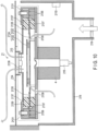
- FIG. 3 is a cross-sectional view showing the coagulation reaction unit 21 in a section that passes through the vicinity of the rotation axis of the coagulation reaction unit 21 and is vertically parallel to the coagulation reaction unit 21.
- the coagulation reaction unit 21 includes a supporter 212 (see FIG. 4 ), a reaction bath 213, a cover 214, and a rotation connector 215.
- the supporter 212 supports the entire coagulation reaction unit 21.
- the reaction bath 213 is attached to the upper portion of the supporter 212.
- the reaction bath 213 is a rotary reaction bath configured to rotate with respect to the supporter 212 with the assistance of the driving mechanism 4.
- the driving mechanism 4 that causes the reaction bath 213 to rotate is formed of, for example, a stepping motor.
- the driving mechanism 4 that causes the reaction bath 213 to rotate is an example of a driver.
- the reaction bath 213 holds the plurality of reaction tubes 211 that contain a mixed solution of a specimen and a reagent, and repeats rotating and stopping to convey the held reaction tubes 211.
- the cover 214 is a cover provided on the upper portion of the reaction bath 213 in order to prevent external light from entering the reaction bath 213.
- the cover 214 is detachably attached to, for example, the inner wall of the analysis mechanism 2 located in the vicinity of the coagulation reaction unit 21.
- the cover 214 does not rotate along with the reaction bath 213.
- the cover 214 may be detachably attached to the supporter 212.
- the rotation connector 215 is a connector for supplying power for activating respective devices provided in the reaction bath 213 from the outside of the coagulation reaction unit 21, and for signals and data generated by the respective devices provided in the reaction bath 213 to the outside of the coagulation reaction unit 21.
- the respective devices provided in the reaction bath 213 include a photometry port 2131, a heater 2136, a temperature sensor, etc., which will be described later.
- the rotation connector 215 electrically connects the remaining units excluding the reaction bath of the analysis mechanism 2, the analysis circuit 3, and the external units such as the control circuit 9 and a power supply device to the photometry port 2131 provided inside the coagulation reaction unit 21, which will be described later.
- the rotation connector 215 is a connector that can provide electrical connection between a rotating body and a fixed object.
- a slip ring is used as the rotation connector 215.
- Other connectors having the same function as that of the slip ring for example, a connector that provides electrical connection through contact via liquid metal
- Each of the analysis mechanism 2, the analysis circuit 3, the control circuit 9, and the power supply device is an example of the second unit.
- FIG. 4 is a perspective view showing the configuration of the reaction bath 213.
- the reaction bath 213 includes an exterior 2130 and a plurality of photometry ports 2131.
- FIG. 5 is a perspective view showing a state in which the exterior 2130 is removed from the reaction bath 213 shown in FIG. 4 .
- the reaction bath 213 also includes a first substrate 2132, a second substrate 2133, and a plurality of third substrates 2135.
- the reaction bath 213 holds the plurality of photometry ports 2131 aligned in an annular arrangement.
- the photometry port 2131 is provided inside the reaction bath 213.
- the photometry port 2131 is fixed inside the reaction bath 213 and rotates along with the reaction bath 213.
- One photometry port 2131 is provided for each of the plurality of reaction tubes 211 installed in the reaction bath 213.
- one reaction tube 211 is installed in each of the photometry ports 2131.
- Each photometry port 2131 optically measures a given component in a mixed solution of a specimen and a reagent discharged into the reaction tube 211.
- the photometry ports 2131 are all the same in configuration.
- FIG. 6 is a perspective view showing the configuration of each of the photometry ports 2131.
- FIG. 6 shows a single photometry port 2131 removed from the reaction bath 213.
- the photometry port 2131 has a reaction tube holder 21311, a light source 21312, and a light receiver 21313.
- the photometry ports 2131 may not be the same in configuration. For example, only some of the photometry ports may be provided with a plurality of light sources 21312.
- the reaction tube 211 is installed in the reaction tube holder 21311.
- the reaction tube holder 21311 is a hole into which the reaction tube 211 is inserted.
- Each of the photometry ports 2131 is provided with, for example, one reaction tube holder 21311, one light source 21312, and one light receiver 21313.
- one light source 21312 and one light receiver 21313 are provided for each reaction tube holder 21311.
- the light source 21312 and the light receiver 21313 are examples of a photometry portion that performs photometry on a mixed solution housed in the reaction tube 211 installed in the reaction tube holder 21311.
- the light receiver 21313 is, for example, a photodetector including a photodiode.
- the photometry port 2131 emits light from the light source 21312 under the control of the control circuit 9.
- the photometry port 2131 detects, through the light receiver 21313, scattered light that is generated by emitting light to the reaction tube 211 inserted into the reaction tube holder 21311. Specifically, the light receiver 21313 detects scattered light of the light emitted to the mixed solution inside the reaction tube 211. The photometry port 2131 converts the light detected by the light receiver 21313 into a weak electrical signal, and outputs the converted electrical signal to the substrate unit 2134 via the third substrate 2135.
- the light source 21312 and the light receiver 21313 are examples of a photometry portion.
- FIG. 7 is an enlarged view of the vicinity of the photometry port 2131 shown in FIG. 3 .
- FIG. 7 shows a state in which the reaction tube 211 is installed in the photometry port 2131.
- the reaction bath 213 includes a heater 2136.
- Each photometry port 2131 is retained at a constant temperature by the heater 2136 provided inside the reaction bath 213.
- the heater 2136 is arranged below each photometry port 2131.
- the heater 2136 is, for example, a heating wire. Examples of a material of the heating wire include nichrome wire and iron chrome wire.
- FIG. 7 shows the example in which the heater 2136 is composed of two heating wires in an annular arrangement. The heater 2136 heats the photometry port 2131 under the control of the control circuit 9.
- a temperature sensor may be provided in the vicinity of the photometry port 2131.
- the temperature sensor for example, a thermistor, a resistance temperature detector, a thermocouple, a temperature sensor IC, etc.
- the temperature sensor measures an ambient temperature and outputs information on the measured temperature to the control circuit 9.
- the control circuit 9 uses the temperature information for temperature control to retain the temperature of the mixed solution housed in the reaction tube 211 installed in the photometry port 2131 at a constant temperature. For this reason, the heater 2136 may be called a "constant temperature portion".
- the first substrate 2132 and the second substrate 2133 are, for example, rigid substrates.
- the first substrate 2132 and the second substrate 2133 are fixed to the inside of the reaction bath 213.
- Each of the first substrate 2132 and the second substrate 2133 is formed in a disc shape with its center being open and is fixed to the vicinity of the center of the reaction bath 213.
- the first substrate 2132 and the second substrate 2133 are electrically connected to each other via a cable (not shown), etc., and function as the single substrate unit 2134.
- Each of the third substrates 2135 extends from the inside to the outside in the reaction bath 213.
- the third substrates 2135 are, for example, flexible printed circuits (FPC).
- FPC flexible printed circuits
- Each of the third substrates 2135 has one end connected to the substrate unit 2134 and the other end connected to one of the plurality of photometry ports 2131.
- Each of the third substrates 2135 electrically connects between the substrate unit 2134 and the corresponding photometry port 2131.
- the third substrates 2135 may be connected to the second substrate 2133.
- a cable may be used instead of the third substrates 2135.
- the substrate unit 2134 is fixed to the inside of the reaction bath 213 and is connected to each of the plurality of photometry ports 2131. Specifically, the substrate unit 2134 is electrically connected to the rotation connector 215 via a cable (not shown), etc. A cable that connects between the rotation connector 215 and the substrate unit 2134 may be connected to the first substrate 2132 or may be connected to the second substrate 2133. Power supplied from the outside to the reaction bath 213 via the rotation connector 215 is supplied to the respective photometry ports 2131 via the substrate unit 2134 and the third substrates 2135, and measurement is performed at each of the photometry ports 2131.
- the substrate unit 2134 is an example of a first unit.
- the substrate unit 2134 has a function of supplying power acquired from the power source arranged outside the reaction bath 213 to each of the photometry ports 2131 (hereinafter referred to as a "power supplying function"), and a function of processing signals acquired from the photometry ports 2131 each having the photometry unit (hereinafter referred to as a "signal processing function").
- the power supply function is an example of the first function
- the signal processing function is an example of the second function.
- the substrate unit 2134 acquires from the photometry port 2131 an analog signal indicating a photometry result at the photometry port 2131, amplifies the acquired analog signal, converts the amplified analog signal into a digital signal, and outputs the converted digital signal to the outside of the coagulation reaction unit 21.
- a field-programmable gate array (FPGA) and a circuit having an amplifier function and an A/D converter function are formed on the substrate of the substrate unit 2134.
- the substrate unit 2134 acquires an analog signal from each photometry port 2131 using the FPGA, amplifies the acquired analog signal using the amplifier function, converts the amplified analog signal into a digital signal using the A/D converter function, and outputs the converted digital signal to the analysis circuit 3 via the rotation connector 215 using the FPGA.
- the substrate unit 2134 acquires electrical signals from all of the photometry ports 2131 every 0.1 seconds.
- a circuit having other functions may be mounted on the substrate of the substrate unit 2134.
- Each of the photometry ports 2131 and the external units are connected together via the substrate unit 2134 connected to each of the photometry ports 2131.
- the number of wires that connect between the external units and the substrate unit 2134 is smaller than the number of wires that connect between the substrate unit 2134 and the photometry ports 2131. That is, use of the substrate unit 2134 can reduce the number of cables for connecting between the reaction bath 213 and the external units and the number of wires and contacts in the rotation connector 215.
- transmission of digital data from the substrate unit 2134 to the analysis circuit 3 is performed by serial communication, for example. This case can further reduce the number of cables that connect between the reaction bath 213 and the external unit.
- the coagulation reaction unit 21 is provided with a mechanism (hereinafter referred to as a heat suppressor) that suppresses heat generated in the substrate unit 2134 from being transmitted to the photometry ports 2131.
- the heat suppressor prevents the heat generated in the substrate unit 2134 from affecting the constant temperature function for the photometry ports 2131.
- a heat insulator 2137 is provided as the heat suppressor inside the reaction bath 213.
- the heat insulator 2137 is a ring-shaped member arranged between the photometry ports 2131 and the substrate unit 2134 and extending in an annular shape, and is fixed to each of the upper side and the lower side of the third substrates 2135.
- the heat insulator 2137 is made of, for example, a material with low thermal conductivity. Examples of a material forming the heat insulator 2137 include, for example, polyethylene foam, urethane foam, phenol resin foam, polyethylene foam, glass wool, cellulose fiber, wool breath, and carbonized cork.
- the heat insulator 2137 functions as a partition between an area in which the photometry ports 2131 are arranged and an area in which the substrate unit 2134 is arranged.
- the third substrates 2135 pass through a gap in the heat insulator 2137 to extend from the area in which the photometry ports 2131 are arranged to the area in which the substrate unit 2134 is arranged.
- heat transfer is suppressed between the area in which the photometry ports 2131 are arranged and the area in which the substrate unit 2134 is arranged. This suppresses heat generated in the substrate unit 2134 from being transferred to the photometry ports 2131.
- the heat insulator 2137 is an example of a suppressor.
- the heat insulator 2137 may be formed by stacking a plurality of heat insulating materials, and the third substrate 2135 may be caused to pass between the stacked materials.
- the heat insulator 2137 may be formed of an integrated heat insulating material having an opening, and the third substrate 2135 may be caused to pass through the opening.
- the reaction bath 213 is provided with, as a heat suppressor, both a fan 2138 for cooling the substrate unit 2134 and a vent 2139.
- the fan 2138 and the vent 2139 are provided in a space in which the substrate unit 2134 is arranged.
- the fan 2138 is attached to a portion of the exterior 2130, the portion forming the upper surface of the reaction bath 213.
- the fan 2138 is arranged, for example, in the center of the reaction bath 213 above the substrate unit 2134.
- the fan 2138 communicates the inside and the outside of the reaction bath 213.
- the fan 2138 includes a propeller and a motor that rotates the propeller.
- the motor of the fan 2138 is electrically connected to the rotation connector 215 via a cable (not shown), etc.
- the motor is driven by power being supplied from the outside via the rotation connector 215, thereby causing the propeller to rotate.
- the fan 2138 exhausts air inside the reaction bath 213 to the outside of the reaction bath 213.
- the fan 2138 is an example of a first fan.
- the fan 2138 generates a flow of air that cools the substrate unit 2134.
- the vent 2139 is provided, for example, at the bottom of the reaction bath 213.
- the vent 2139 is a hole that communicates the outside and the inside of the reaction bath 213.
- the number of vents 2139 may be one, or a plurality of vents 2139 may be provided.
- FIG. 8 is a diagram for explaining the flow of air inside the reaction bath 213 shown in FIG. 3 .
- the air below the reaction bath 213 flows into the reaction bath 213 via the vent 2139.
- the substrate unit 2134 is cooled down.
- the control circuit 9 controls the setting and updating operation of execution information based on the analysis request information, the moving operation of the specimen racks 221, the rotating and dispensing operation of the specimen dispensing arm 25, the rotating operation of the reagent rack, the rotating and dispensing operation of the first reagent dispensing arm 26, the rotating and dispensing operation of the second reagent dispensing arm 27, the rotating and dispensing operation of the reaction tube arm 28, etc.
- the control circuit 9 controls the rotating operation of the reaction bath 213, the measurement operation by the photometry port 2131, the heat generation state of the heater 2136, the activation state of the fan 2138, etc.
- the automatic analyzer 1 includes the reaction bath 213, the plurality of photometry ports 2131 fixed to the reaction bath 213, and the driving mechanism 4.
- Each of the photometry ports 2131 includes the reaction tube holder 21311 that houses a mixed solution of a specimen and a reagent, and the light source 21312 and the light receiver 21313 both serving as a photometry portion that measures the mixed solution housed in the reaction tube 211.
- the light source 21312 and the light receiver 21313 are provided for each reaction tube holder 21311.
- the reaction bath 213 includes the plurality of photometry ports 2131, and repeats rotating and stopping to convey the reaction tube 211 held by the reaction tube holder 21311.
- the driving mechanism 4 causes the reaction bath 213 to rotate.
- the reaction bath 213 for the blood coagulation measurement to be performed is formed into a circular shape, and is rotated by the driving mechanism 4.
- a plurality of photometry portions called the photometry ports 2131 are fixed to the inside of the reaction bath 213, and the measurement is performed by installing the disposable reaction tube 211 in each of the photometry ports 2131.
- the measurement using the plurality of photometry ports 2131 realizes improved examination throughput as compared to the case of using only one photometry portion.
- use of the rotary reaction bath 213 enables the reaction tubes 211 installed in the photometry ports 2131 to be conveyed.
- This enables dispersion of a specimen and a reagent to each reaction tube 211 and installation and removal of each reaction tube 211 at a specific position.
- This can -simplify and downsize the configuration and operation of the mechanism for dispensing specimens and reagents into the reaction tubes 211 and the mechanism for installing and removing the reaction tubes 211. That is, this can simplify the operation of the mechanism for accessing the reaction bath 213 configured to perform the blood coagulation, optimize the number of units provided in the automatic analyzer 1 and the size of the entire automatic analyzer 1, and also improve the examination throughput.
- the automatic analyzer 1 further includes the substrate unit 2134.
- the substrate unit 2134 is provided inside the reaction bath 213 and is connected to each of the plurality of photometry ports 2131.
- the substrate unit 2134 has the power supplying function of supplying power acquired from the power supply provided outside the reaction bath 213 to each of the photometry ports 2131 and the signal processing function of processing signals acquired from the photometry ports 2131.
- the signal processing function has a function of, for example, acquiring from each of the photometry ports 2131 an analog signal indicating a photometry result function at the corresponding photometry port 2131, a function of amplifying the acquired analog signal, a function of converting the amplified analog signal into a digital signal, and a function of outputting the converted digital signal to the outside of the reaction bath 213.
- Each of the photometry ports 2131 and the external units are connected together using the substrate unit 2134 connected to each of the photometry ports 2131.
- the number of wires that connect between the external units and the substrate unit 2134 is smaller than the number of wires that connect between the substrate unit 2134 and the photometry ports 2131. This can reduce the number of cables that connect between the respective photometry ports 2131 and the external units and the number of wires and contacts in the rotation connector 215.
- the automatic analyzer 1 further includes the rotation connector 215 that electrically connects between the external units of the reaction bath 213 and the photometry ports 2131.
- the rotation connector 2115 For example, a slip ring is used as the rotation connector 215.
- Use of the rotation connector 215 enables transmission of power for activating the photometry ports 2131 between the photometry ports 2131 rotating along with the reaction bath 213 and the external units and transmission of an electric signal indicating a photometry result at the corresponding photometry port 2131.
- the reaction bath 213 according to the present embodiment further includes a heat suppressor that suppresses heat generated in the substrate unit 2134 from being transferred to the photometry ports 2131. This configuration suppresses the heat generated in the substrate unit 2134 from affecting the constant temperature function for the photometry ports 2131.
- the reaction bath 213 includes a heat insulator 2137 as a heat suppressor.
- the heat insulator 2137 is made of a material with low thermal conductivity and functions as a partition provided between each of the photometry ports 2131 and the substrate unit 2134 inside the reaction bath 213.
- the heat insulator 2137 being provided, the space in which the photometry ports 2131 are arranged and the space in which the substrate unit 2134 is arranged are separated, and the heat generated in the substrate unit 2134 is suppressed from being transmitted to the photometry ports 2131.
- the reaction bath 213 includes, as a heat suppressor, the fan 2138 that exhausts air inside the reaction bath 213 to the outside of the reaction bath 213, and the vent 2139 that causes air outside the reaction bath 213 to flow into the reaction bath 213.
- the fan 2138 and the vent 2139 By providing the fan 2138 and the vent 2139, an air flow is generated inside the reaction bath 213, and the substrate unit 2134 is cooled down by the generated air flow.
- the substrate unit 2134 being cooled, the heat generated in the substrate unit 2134 is suppressed from being transferred to the photometry ports 2131.
- a first modification of the embodiment will be described.
- the configuration of the embodiment is modified as will be described below.
- the present modification is provided with, as a mechanism for cooling the substrate unit 2134, a second fan configured to cool down air outside the reaction bath 213, in addition to the fan 2138 provided inside the reaction bath 213. Descriptions of the structures, operations, and advantageous effects similar to those of the embodiment will be omitted.
- FIG. 9 is a diagram showing an internal configuration of the coagulation reaction unit 21.
- FIG. 9 is a cross-sectional view showing the coagulation reaction unit 21 in a section that passes through the vicinity of the rotation axis of the coagulation reaction unit 21 and is vertically parallel to the coagulation reaction unit 21.
- the coagulation reaction unit 21 further includes, as the heat suppressor, a fan 216 and a temperature sensor 217.
- the fan 216 is provided outside the reaction bath 213, and causes air in the vicinity of the vent 2139 to flow.
- the fan 216 is arranged below the reaction bath 213.
- the fan 216 is attached to, for example, the inner wall of the analysis mechanism 2 located in the vicinity of the coagulation reaction unit 21.
- the fan 216 may be fixed to the supporter 212.
- the fan 216 cools air present in the space below the reaction bath 213 by circulating it.
- the fan 216 sends air present in the space below the reaction bath 213 to the outside, thereby circulating air present in the space below the reaction bath 213.
- the cooled air passes through the vent 2139 to flow into the reaction bath 213.
- the fan 216 is an example of a second fan.
- the temperature sensor 217 is a sensor that detects a temperature of ambient air.
- the fan 216 is fixed to the supporter 212 below the reaction bath 213.
- the temperature sensor 217 detects a temperature of air cooled by the fan 216.
- a thermistor, a resistance temperature detector, a thermocouple, a temperature sensor IC, etc. are used as the temperature sensor 217.
- the temperature sensor 217 outputs information on the measured temperature to the control circuit 9.
- the control circuit 9 controls the activation state of the fan 216 in accordance with a detection result by the temperature sensor 217. For example, in the case where the temperature detected by the temperature sensor 217 is equal to or smaller than a set value, the control circuit 9 determines that air for use in cooling the substrate unit 2134 has a sufficiently low temperature, and brings the fan 216 to a stop state. On the other hand, in the case where the temperature detected by the temperature sensor 217 exceeds the set value, the control circuit 9 determines that air for use in cooling the substrate unit 2134 has been warmed, and activates the fan 216 to cool the air for use in cooling the substrate unit 2134.
- the control circuit 9 is an example of the controller.
- the automatic analyzer 1 aspirates air below the reaction bath 213 using the vent 2139, and cools the substrate unit 2134 using the aspirated air. Therefore, in the case where heat is accumulated within the automatic analyzer 1 and the air itself for use in cooling is warm, the cooling effects on the substrate unit 2134 are undesirably decreased.
- the automatic analyzer 1 further includes the fan 216 provided outside the reaction bath 213 and configured to cause air in the vicinity of the vent 2139 to flow.
- the fan 216 By the fan 216 being provided, air for use in cooling the substrate unit 2134 circulates, thereby preventing the accumulation of heat inside the automatic analyzer 1. This can inhibit the increase in temperature of air for use in cooling the substrate unit 2134, thereby improving the capacity of cooling the substrate unit 2134.
- the automatic analyzer 1 includes the temperature sensor 217 configured to detect a temperature of air in the vicinity of the vent 2139, and the control circuit 9 configured to control the activation state of the fan 216 in accordance with the temperature detected by the temperature sensor 217. For example, by causing the temperature sensor 217 to monitor a temperature of air for use in cooling the substrate unit 2134 and by activating the fan 216 only in the case where the temperature of air exceeds a set value, the capacity of cooling the substrate unit 2134 can be improved effectively with less power.
- the fan 216 may be activated all the time while the measurement is performed in the coagulation reaction unit 21 without controlling the fan 216 using the temperature sensor 217. In this case, the temperature sensor 217 may be omitted.
- the temperature sensor 217 may be arranged inside the reaction bath 213.
- the temperature sensor 217 detects a temperature of air that has flowed into the reaction bath 213 through the vent 2139, and outputs a result of the detection to the control circuit 9 via the rotation connector 215.
- the control circuit 9 controls the activation state of the fan 216 in accordance with a temperature of air that has flowed into the reaction bath 213, thereby inhibiting the increase in temperature of air for use in cooling the substrate unit 2134.
- a second modification of the embodiment will be described.
- the configuration of the embodiment is modified as will be described below.
- the present modification is provided with, as a mechanism for cooling the substrate unit 2134, a fence for retaining air in the space below the reaction bath in addition to the fan 2138 provided inside the reaction bath 213. Descriptions of the configurations, operations, and advantageous effects similar to those of the embodiment will be omitted.
- FIG. 10 is a diagram showing an internal configuration of the coagulation reaction unit 21.
- FIG. 10 is a cross-sectional view showing the coagulation reaction unit 21 in a section that passes through the vicinity of the rotation axis of the coagulation reaction unit 21 and is vertically parallel to the coagulation reaction unit 21.
- the coagulation reaction unit 21 includes, as the heat suppressor, a storage 218, a fan 219, and a temperature sensor 2110.
- the storage 218 is provided outside the reaction bath 213.
- the storage 218 is fixed to the supporter 212 (not shown) below the reaction bath 213.
- the storage 218 stores air that will flow into the reaction bath 213 through the vent 2139.
- the storage 218 is formed of a fence surrounding air that will flow into the reaction bath 213 via the vent 2139.
- the fence forming the storage 218 is formed of, for example, a metal plate.
- the fan 219 is attached to the storage 218.
- the fan 219 causes air outside the storage 218 to flow into the storage 218, thereby reducing the accumulation of heat inside the storage 218 and inhibiting the increase in temperature of air for use in cooling the substrate unit 2134.
- the air that has flowed into the storage 218 flows into the reaction bath 213 through the vent 2139 and is used for cooling the substrate unit 2134.
- the fan 219 is an example of a third fan.
- the temperature sensor 2110 is a sensor attached to the inside of the storage 218 and configured to detect a temperature of air inside the storage 218.
- a thermistor for example, a thermistor, a resistance temperature detector, a thermocouple, a temperature sensor IC, etc., are used.
- the temperature sensor 2110 outputs information on the detected temperature to the control circuit 9.
- the control circuit 9 controls the activation state of the fan 219 in accordance with a detection result by the temperature sensor 2110. For example, in the case where the temperature detected by the temperature sensor 2110 is equal to or smaller than a set value, the control circuit 9 determines that air inside the storage 218 has a sufficiently low temperature, and brings the fan 216 to a stop state. On the other hand, in the case where the temperature detected by the temperature sensor 2110 exceeds the set value, the control circuit 9 determines that air inside the storage 218 has been warmed, and activates the fan 219.
- the control circuit 9 is an example of the controller.
- the automatic analyzer 1 further includes the storage 218 provided outside the reaction bath 213 and configured to store air that will flow into the reaction bath 213 through the vent 2139, and the fan 219 provided in the storage 218 and configured to cause air outside the storage 218 to flow into the storage 218.
- the fan 219 being provided in the storage 218 in which air for use in cooling the substrate unit 2134 is stored, the air for use in cooling the substrate unit 2134 can be replaced effectively, thereby improving the capacity of cooling the substrate unit 2134.
- the automatic analyzer 1 includes the temperature sensor 2110 configured to detect a temperature of air inside the storage 218, and the control circuit 9 configured to control the activation state of the fan 219 in accordance with the temperature detected by the temperature sensor 2110. For example, by causing the temperature sensor 2110 to monitor a temperature of air inside the storage 218 and by activating the fan 219 only in the case where the temperature of air exceeds a set value, the capacity of cooling the substrate unit 2134 can be improved effectively with less power.
- the fan 219 may be activated all the time while the measurement is performed in the coagulation reaction unit 21 without controlling the fan 219 using the temperature sensor 2110. In this case, the temperature sensor 2110 may be omitted.
- the temperature sensor 2110 may be arranged inside the reaction bath 213.
- the temperature sensor 2110 detects a temperature of air that has been introduced into the storage 218 by the fan 219 and caused to flow into the reaction bath 213 through the vent 2139, and outputs a result of the detection to the control circuit 9 through the rotation connector 215.
- the control circuit 9 controls the activation state of the fan 219 in accordance with a temperature of air that has flowed into the reaction bath 213, thereby inhibiting the increase in temperature of air for use in cooling the substrate unit 2134.
- a third modification of the embodiment will be described.
- the configuration of the embodiment is modified as will be described below.
- an area in which heating elements are arranged in a concentrated manner is provided on the substrate, and a mechanism for cooling the substrate unit 2134 is arranged in the vicinity of this area. Descriptions of the configurations, operations, and advantageous effects similar to those of the embodiment will be omitted.
- FIG. 11 is a diagram showing an internal configuration of the coagulation reaction unit 21 according to the present modification.
- FIG. 11 is a cross-sectional view showing the coagulation reaction unit 21 in a section that passes through the vicinity of the rotation axis of the coagulation reaction unit 21 and is vertically parallel to the coagulation reaction unit 21.
- the second substrate 2133 forming the substrate unit 2134 is provided with a heating concentrator 21331.
- the heating concentrator 21331 elements arranged on the second substrate 2133 are arranged in a concentrated manner. By this, the amount of heat generated in the heating concentrator 21331 becomes larger than that of the remaining area on the second substrate 2133 while the measurement in the coagulation reaction unit 21 is performed.
- the fan 2138 is provided in the vicinity of the heating concentrator 21331, and under the control of the control circuit 9, cools the heating concentrator 21331.
- the fan 2138 is arranged in such a manner as to cool the heating concentrator 21331 in a concentrated manner by sending air toward the heating concentrator 21331.
- the fan 2138 is arranged directly below the heating concentrator 21331, as shown in FIG. 11 .
- the fan 2138 may be arranged above or beside the substrate unit 2134 as long as the fan 2138 can cool the heating concentrator 21331 in a concentrated manner.
- the fan 2138 circulates air inside the reaction bath 213 by flowing air outside the reaction bath 213 into the reaction bath 213.
- the second substrate 2133 of the substrate unit 2134 is provided with the heating concentrator 21331 in which heat generating elements are arranged in a concentrated manner.
- the fan 2138 is provided in the vicinity of the heating concentrator 21331. This configuration enables the heating concentrator 21331 having the heat generating elements arranged in a concentrated manner to be cooled by the fan 2138 in a concentrated manner, so that the capacity of cooling the substrate unit 2134 can be improved.
- a fourth modification of the embodiment will be described.
- the configuration of the embodiment is modified as will be described below. Descriptions of the configurations, operations, and advantageous effects similar to those of the embodiment will be omitted.
- one of the power supplying function and the signal processing function which are both installed in the substrate unit 2134 in the above embodiment, is installed in the substrate unit 2134 and the other function is installed in an external unit.
- the power supplying function for each of the photometry ports 2131 may be installed in the power supply device instead of the substrate unit 2134.
- the signal processing function for each of the photometry ports 2131 may be installed in the analysis circuit 3 instead of the substrate unit 2134.
- a fifth modification of the embodiment will be described.
- the configuration of the embodiment is modified as will be described below. Descriptions of the configurations, operations, and advantageous effects similar to those of the fifth embodiment will be omitted.
- the power supplying function and the signal processing function which are both installed in the substrate unit 2134 in the above embodiment, are both installed in the external unit.
- the power supplying function for each of the photometry ports 2131 may be installed in the power source device instead of the substrate unit 2134
- the signal processing function for each of the photometry ports 2131 may be installed in the analysis circuit 3 instead of the substrate unit 2134.
- the substrate unit 2134 may be omitted.
- a sixth modification of the embodiment will be described. Descriptions of the configurations, operations, and advantageous effects similar to those of the embodiment will be omitted.
- the configuration of the embodiment is modified as will be described below.
- the fan 2138 rotates in the reverse direction from that of the present embodiment, and causes air outside the reaction bath 213 to flow into the reaction bath 213. Then, air flows in the reverse direction from the direction of air flow shown in FIG. 8 . Air inside the reaction bath 213 is exhausted to the outside of the reaction bath 213 through the vent 2139.
- the substrate unit 2134 is cooled down.
- examination throughput by the automatic analyzer can be improved.
Landscapes
- Chemical & Material Sciences (AREA)
- Physics & Mathematics (AREA)
- Health & Medical Sciences (AREA)
- Life Sciences & Earth Sciences (AREA)
- Analytical Chemistry (AREA)
- Biochemistry (AREA)
- General Health & Medical Sciences (AREA)
- General Physics & Mathematics (AREA)
- Immunology (AREA)
- Pathology (AREA)
- Chemical Kinetics & Catalysis (AREA)
- Automatic Analysis And Handling Materials Therefor (AREA)
Abstract
Description
- Embodiments described herein relate generally to an automatic analyzer.
- An automatic analyzer measures a mixed solution of a specimen and a reagent to be measured, thereby measuring components in the specimen. For example, in the case of performing a blood coagulation analysis test on a blood sample, a disposable reaction tube is installed in a reaction bath, and the blood sample and the reagent are dispensed into the installed reaction tube. Then, the mixed solution of the blood sample and the reagent dispensed into the reaction tube is measured using the photometry ports each including a photometry portion. A holder configured to hold the reaction tube and the photometry ports is fixed with respect to a reaction bath, and the reaction bath is fixed inside the apparatus.
- In order for an automatic analyzer configured to perform such a blood coagulation analysis test to improve test throughput, for example, there is a method of increasing the number of photometry ports. However, increasing the photometry ports complicates a mechanism for installing a disposable reaction tube in a reaction bath, a mechanism for removing the reaction tube from the reaction bath, and a mechanism for dispensing a blood sample and a reagent. Furthermore, an increase in the number of photometry ports requires upsizing of a reaction bath or an increase in the number of reaction baths, thereby undesirably increasing the overall size of the apparatus.
- An automatic analyzer comprising: a plurality of reaction tube holders each configured to hold a reaction tube housing a mixed solution of a specimen and a reagent; a plurality of photometry portions respectively provided with respect to the reaction tube holders and each configured to perform photometry on the mixed solution housed in the reaction tube; a reaction bath including the reaction tube holders and the photometry portions and configured to repeat rotating and stopping to thereby convey the reaction tube held by each of the reaction tube holders; and a driver configured to rotate the reaction bath.
- The automatic analyzer may further comprise a first unit fixed to an inside of the reaction bath and connected to each of the photometry portions, wherein the first unit may include at least one of a first function for supplying power acquired from a power source to each of the photometry portions, or a second function for processing a signal acquired from each of the photometry portions.
- The automatic analyzer may further comprise a rotation connector configured to electrically connect between a second unit provided outside the reaction bath, and the first unit.
- The rotation connector electrically connects between the second unit and each of the photometry portions via the first unit. The rotation connector supplies electric power for activating respective devices provided in the reaction bath from the outside of the coagulation reaction bath, and outputs signals and data generated by the respective devices provided in the reaction bath to the outside of the coagulation reaction bath.
- The rotation connector is a connector that can provide electrical connection between a rotating body and a fixed object. The rotation connector may be a slip ring.
- The first unit may be a substrate formed into a disc shape with its center being open.
- The automatic analyzer may further comprise a flexible printed circuit configured to electrically connect between the first unit and one of the photometry portions. Power supplied from the outside to the reaction bath via the rotation connector is supplied to the respective photometry portions via the first unit and the flexible printed circuit.
- The second unit may include one or more of: an analysis mechanism configured to sequentially measure optical property values of the mixed solution of the specimen or the standard solution and the reagent; an analysis circuit configured to generate calibration data and analysis data on coagulation of the blood sample by analyzing the standard data and the subject data generated by the analysis mechanism; a control circuit configured to function as a center of the automatic analyzer; and a power supply device configured to supply power to each of the mechanisms of the automatic analyzer.
- Wires that connect between the second unit provided outside the reaction bath and the first unit may be smaller in number than wires that connect between the first unit and each of the photometry portions. Use of the first image can reduce the number of cables for connecting between the reaction bath and the external units and the number of wires and contacts in the rotation connector. Furthermore, transmission of digital data from the first unit to the outside may be performed by serial communication.
- The second function may include: a function of acquiring from each of the photometry portions an analog signal indicating a photometry result by the corresponding photometry portion; a function of amplifying the acquired analog signal; a function of converting the amplified analog signal to a digital signal; and a function of outputting the converted digital signal to the second unit.
- The automatic analyzer may further comprise a heat suppressor configured to suppress heat generated in the first unit from being transferred to the photometry portions.
- The heat suppressor may be made of a material with low thermal conductivity and including a partition provided between the photometry portions and the first unit inside the reaction bath.
- The heat suppressor may include a first fan configured to generate a flow of air for cooling the first unit.
- The heat suppressor may include a vent for allowing air outside the reaction bath to flow into the reaction bath, and the first fan may exhaust air inside the reaction bath to an outside of the reaction bath.
- The heat suppressor may include a vent for allowing air outside the reaction bath to flow into the reaction bath, and the first fan may cause air outside the reaction bath to flow into the reaction bath.
- The automatic analyzer may further comprise a second fan provided outside the reaction bath and configured to cause air in a vicinity of the vent to flow.
- The automatic analyzer may further comprise: a sensor configured to detect a temperature of air in the vicinity of the vent; and a controller configured to control an activation state of the second fan in accordance with a detection result by the sensor.
- The automatic analyzer may further comprise: a storage provided outside the reaction bath and configured to store air which is to flow into the reaction bath through the vent; and a third fan provided in the storage and configured to cause air outside the storage to flow into the storage.
- The automatic analyzer may further comprise: a sensor configured to detect a temperature of air inside the storage; and a controller configured to control an activation state of the third fan in accordance with a detection result by the sensor.
- The first unit may include a heating concentrator in which heat generating elements are arranged in a concentrated manner, and the fan may be provided in a vicinity of the heating concentrator.
- The first unit may include one of the first function and the second function, and the second unit may include another one of the first function and the second function, which is different from the one included in the first unit.
- The rotation connector may electrically connect between the first unit and the second unit through contact between solid forms.
- The rotation connector may electrically connect between the first unit and the second unit through contact via liquid metal.
- The rotation connector may include a slip ring configured to provide electrical connection through contact between solid forms.
- The rotation connector may electrically connect between the second unit and the first fan.
- An automatic analyzer comprising: a plurality of reaction tube holders each configured to hold a reaction tube housing a mixed solution of a specimen and a reagent; a plurality of photometry portions respectively provided with respect to the reaction tube holders and each configured to perform photometry on the mixed solution housed in the reaction tube; a reaction bath including the reaction tube holders and the photometry portions and configured to repeat rotating and stopping to thereby convey the reaction tube held by the reaction tube holders; a driver configured to rotate the reaction bath; a processing unit provided outside the reaction bath; and a rotation connector configured to connect between the photometry portions and the processing unit.
- An automatic analyzer may comprise: a plurality of reaction tube holders each configured to hold a reaction tube housing a mixed solution of a specimen and a reagent; a plurality of photometry portions respectively provided with respect to the reaction tube holders and each configured to perform photometry on the mixed solution housed in the reaction tube; a reaction bath including the reaction tube holders and the photometry portions and configured to rotate to thereby convey the reaction tube held by each of the reaction tube holders; and a driver configured to rotate the reaction bath.
- The automatic analyzer may further comprise a first unit fixed to the reaction bath and connected to each of the photometry portions. The first unit includes at least one of a first function for supplying power acquired from a power source to each of the photometry portions, or a second function for processing a signal acquired from each of the photometry portions.
-
-
FIG. 1 is a diagram showing a configuration of an automatic analyzer according to an embodiment. -
FIG. 2 is a diagram showing a configuration of an analysis mechanism for the automatic analyzer according to the embodiment. -
FIG. 3 is a cross-sectional view showing an internal configuration of a coagulation reaction unit of the automatic analyzer according to the embodiment. -
FIG. 4 is a perspective view showing a configuration of a reaction bath of the automatic analyzer according to the embodiment. -
FIG. 5 is a perspective view showing a state in which an exterior is removed from the reaction bath shown inFIG. 4 . -
FIG. 6 is a perspective view showing a configuration of a photometry port of the automatic analyzer according to the embodiment. -
FIG. 7 is an enlarged view of the vicinity of the photometry port shown inFIG. 3 . -
FIG. 8 is a diagram for explaining a flow of air inside the reaction bath shown inFIG. 3 . -
FIG. 9 is a cross-sectional view showing an internal configuration of a coagulation reaction unit of an automatic analyzer according to a first modification. -
FIG. 10 is a cross-sectional view showing an internal configuration of a coagulation reaction unit of an automatic analyzer according to a second modification. -
FIG. 11 is a cross-sectional view showing an internal configuration of a coagulation reaction unit of an automatic analyzer according to a third modification. - In general, according to one embodiment, an automatic analyzer includes: a plurality of reaction tube holders each configured to hold a reaction tube housing a mixed solution of a specimen and a reagent; a plurality of photometry portions respectively provided with respect to the reaction tube holders and each configured to perform photometry on the mixed solution housed in the reaction tube; a reaction bath including the reaction tube holders and the photometry portions and configured to repeat rotating and stopping to thereby convey the reaction tube held by each of the reaction tube holders; and a driver configured to rotate the reaction bath.
- An automatic analyzer and its embodiments will be described in detail with reference to the drawings. In the following description, structural elements having approximately the same function and configuration will be assigned the same reference symbol, and a repeat description will be given only where necessary.
-
FIG. 1 is a block diagram showing a function configuration of an automatic analyzer according to a present embodiment. Anautomatic analyzer 1 shown inFIG. 1 includes ananalysis mechanism 2, ananalysis circuit 3, adriving mechanism 4, aninput interface 5, anoutput interface 6, acommunication interface 7, astorage circuit 8, and a control circuit 9 (controller). Theautomatic analyzer 1 measures a mixed solution of a specimen to be measured, thereby measuring components in the specimen. Theautomatic analyzer 1 according to the present embodiment can perform a blood coagulation analysis test on a blood sample by using the blood sample as a specimen. - The
analysis mechanism 2 mixes a blood sample and each reagent for use in each examination item. In generation of calibration data, theanalysis mechanism 2 mixes a standard solution exhibiting a known concentration, and each reagent for use in each examination item. A mixed solution of a blood sample or the standard solution and the reagent is retained at a constant temperature of, for example, 37 °C, which is optimal for enzymatic reactions in the living body. By this, the blood sample and the reagent react with each other. - The
analysis mechanism 2 sequentially measures optical property values of the mixed solution of the blood sample or standard solution and the reagent. This measurement generates standard data and subject data both represented by, for example, the transmitted light intensity or absorbance and the scattered light intensity. - The
analysis circuit 3 is a processor configured to generate calibration data and analysis data on coagulation of the blood sample by analyzing the standard data and the subject data generated by theanalysis mechanism 2. Theanalysis circuit 3 reads an analysis program from thestorage circuit 8, for example, and analyzes the standard data and the subject data in accordance with the read analysis program. - Specifically, the
analysis circuit 3 measures the process of coagulation in the mixed liquid, for example, by analyzing the subject data. For example, for analysis of a mixed solution with the addition of a reagent involving a strong reaction, theanalysis circuit 3 analyzes the subject data that can be obtained by detecting transmitted light. For example, for analysis of a mixed solution with the addition of a reagent involving a weak and slow reaction, theanalysis circuit 3 analyzes the subject data that can be obtained by detecting scattered light. Theanalysis circuit 3 acquires a change in received light intensity for the blood coagulation reaction based on the subject data. Theanalysis circuit 3 calculates information on coagulation of a blood sample, such as a coagulation end point, a coagulation point, and a coagulation time, from a reaction curve presenting the change in received light intensity. - Depending on the test item, the
analysis circuit 3 calculates a concentration value, etc., based on the calculated coagulation time and calibration data of a test item corresponding to the subject data concerned. Theanalysis circuit 3 outputs analysis data including a coagulation end point, a coagulation point, a coagulation time, a concentration value, etc., to thecontrol circuit 9. - The
driving mechanism 4 drives theanalysis mechanism 2 under the control of thecontrol circuit 9. Thedriving mechanism 4 is realized by, for example, a combination of a gear, a stepping motor, a belt conveyor, a lead screw, and so on. - The
input interface 5 is connected to thecontrol circuit 9 so that it converts operational commands and various information items input by an operator into electric signals and outputs them to thecontrol circuit 9. For example, theinput interface 5 receives, from the operator, an input of analysis request information including information for specifying a specimen to be analyzed and information for specifying a test item of this specimen. The analysis request information may further include an analysis parameter of a test item for the aforementioned specimen. Furthermore, for example, theinput interface 5 receives an input of a shutdown command. Theinput interface 5 is realized by, for example, one or more of a mouse, a keyboard, a touch pad on which instructions are input by touching an operation screen, and the like. - In this disclosure, the
input interface 5 is not limited to physical operating components such as a mouse, a keyboard, and a touch pad. Examples of theinput interface 5 also include a processing circuit for electric signals, which is configured to receive an electric signal corresponding to an operational command input from an external input device separate from theautomatic analyzer 1, and to output this electric signal to thecontrol circuit 9. - The
output interface 6 is connected to thecontrol circuit 9, and outputs the signal supplied from thecontrol circuit 9. Theoutput interface 6 is realized by, for example, one or more of a display circuit, a print circuit, an audio device, and the like. Such a display circuit may include a CRT display, a liquid crystal display, an organic EL display, an LED display, a plasma display, etc. Furthermore, the display circuit may include a processing circuit configured to convert data indicative of a display target into a video signal and externally output the video signal. The print circuit may include a printer, etc. The print circuit may also include an output circuit configured to externally output data indicative of a display target. The audio device may include a speaker, etc. The audio device may also include an output circuit configured to externally output an audio signal. - The
communication interface 7 is connected to, for example, the in-hospital network NW. Thecommunication interface 7 performs data communication with a hospital information system (HIS) via the in-hospital network NW. Thecommunication interface 7 may perform data communication with the HIS via a laboratory information system (LIS) connected to the in-hospital network NW. Instead of theinput interface 5, thecommunication interface 7 may receive operational commands and various information items from the operator via the in-hospital network NW. - The
storage circuit 8 may include a processor-readable storage medium such as a magnetic storage medium, an optical storage medium, or a semiconductor memory. It is not required to realize thestorage circuit 8 by a single storage medium or device. For example, thestorage circuit 8 may be realized by multiple storage devices. - The
storage circuit 8 stores analysis programs for execution by theanalysis circuit 3 and control programs for realization of functions of thecontrol circuit 9. Such a program may be installed in advance in a computer from a network or a non-transitory computer-readable storage medium, for example, so that the program will cause the computer to realize the respective functions of thecontrol circuit 9. Various types of data handled in this disclosure are typically digital data. Thestorage circuit 8 is an example of a storage. - The
storage circuit 8 stores analysis request information received by theinput interface 5 or thecommunication interface 7, and execution information set and updated by thecontrol circuit 9. The execution information is information indicating the progress of analysis executed based on the analysis request information. Furthermore, thestorage circuit 8 stores, for each test item, analysis data generated by theanalysis circuit 3. Thestorage circuit 8 stores a test order input from an operator, etc., or a test order received by thecommunication interface 7 via the in-hospital network NW, etc. - The
control circuit 9 is, for example, a processor functioning as a center of theautomatic analyzer 1. Thecontrol circuit 9 executes the control programs stored in thestorage circuit 8 to realize functions corresponding to the executed programs. Thecontrol circuit 9 may be provided with a storage area for storing at least a portion of the data stored in thestorage circuit 8. - The
control circuit 9 implements the operation program to realize asystem control function 91. Through thesystem control function 91, thecontrol circuit 9 takes total control over the components of theautomatic analyzer 1 based on, for example, input information input via theinput interface 5. Thecontrol circuit 9 is an example of the controller. - The present embodiment will be described assuming that a single processor realizes the
system control function 91; however, the embodiment is not limited to such a configuration. A plurality of independent processors may be combined to form a control circuit, and each of the processors may implement the control program to realize thesystem control function 91. - The term "processor" used herein refers to, for example, a central processing unit (CPU) or a graphics processing unit (GPU), or a circuit such as an application-specific integrated circuit (ASIC), a programmable logic device (such as a simple programmable logic device (SPLD)), a complex programmable logic device (CPLD), a field programmable gate array (FPGA)), etc. In the case of the processor being a CPU, for example, the processor realizes a function by reading and executing a program stored in a storage circuit. On the other hand, in the case of the processor being, for example, an ASIC, instead of a program being stored in a storage circuit, a corresponding function is directly incorporated as a logic circuit in the circuit of the processor. Each processor of the present embodiment is not limited to a configuration as a single circuit; a plurality of independent circuits may be combined into one processor to realize the function of the processor. Furthermore, multiple components or features as given in
FIG. 1 may be integrated as one processor to realize the respective functions. The above description of the "processor" is applicable to the subsequent embodiments and modifications. - Next, a configuration of the
analysis mechanism 2 will be described in detail. -
FIG. 2 is a diagram showing a configuration of theanalysis mechanism 2. Theanalysis mechanism 2 includes acoagulation reaction unit 21, arack sampler 22, areagent storage 23, and areaction tube storage 24. Theanalysis mechanism 2 further includes aspecimen dispensing arm 25, a firstreagent dispensing arm 26, a secondreagent dispensing arm 27, and areaction tube arm 28. - With the assistance of the
driving mechanism 4, theanalysis mechanism 2 conveysreaction tubes 211 held by the annularcoagulation reaction unit 21. Theanalysis mechanism 2 performs, at every analysis cycle, dispensing operation of a blood sample or a standard solution, each serving as a specimen, and a reagent to thereaction tube 211 to be conveyed. Thecoagulation reaction unit 21 may be referred to as a "reaction disk". - The
coagulation reaction unit 21 is configured to measure blood coagulation. Thecoagulation reaction unit 21 holds the plurality ofreaction tubes 211 aligned in an annular arrangement, and conveys the heldreaction tubes 211 along a predetermined path. With the assistance of the driving mechanism, thecoagulation reaction unit 21 alternately repeats rotating and stopping in predetermined time intervals (hereinafter, each time interval will be referred to as an "analysis cycle"). - The
rack sampler 22 movably supports a plurality ofspecimen racks 221 each capable of holding a plurality of specimen containers that contain a specimen for which a measurement request has been made.FIG. 2 shows an example in which the plurality ofspecimen racks 221 are each capable of holding a row of five sample containers. Therack sampler 22 conveys the specimen racks 221 from a feed position in which the specimen racks 221 are fed to a specimen aspiration position in which a specimen is aspirated by a specimen dispensing probe. For example, the specimen aspiration position is set at an intersection between the round trajectory of thespecimen dispensing arm 25 and the traveling path of the specimen racks 221. - The
reagent storage 23 refrigerates and stores a first reagent and a second reagent. Specifically, thereagent storage 23 refrigerates a plurality of reagent containers configured to contain the first reagent that reacts with a given component in a standard specimen and a subject specimen, and refrigerates a plurality of reagent containers configured to contain the second reagent that reacts with a given component in a standard specimen and a subject specimen. The second reagent is, for example, a reagent that forms a pair with the first reagent in the dual-reagent system. The second reagent may be a reagent having the same components and the same concentration as the first reagent. - The
reagent storage 23 is covered by a detachable reagent cover. Thereagent storage 23 encloses a reagent rack in such a manner that the reagent rack can rotate. The reagent rack holds the plurality of reagent containers aligned in an annular arrangement. The reagent rack is driven by thedriving mechanism 4 to thereby rotate and stop at each analysis cycle. - A first reagent aspiration position and a second reagent aspiration position are set at predetermined positions on the
reagent storage 23. The first reagent suction position is set at, for example, an intersection between the round trajectory of the firstreagent dispensing arm 26 and the traveling path of the openings of the reagent containers that contain the first reagent. The second reagent aspiration position is set at, for example, an intersection between the round trajectory of the secondreagent dispensing arm 27 and the traveling path of the openings of the reagent containers that contain the second reagent. - The
reaction tube storage 24 stores the plurality ofreaction tubes 211. Thereaction tube 211 may be formed of, for example, a glass material, a polypropylene (PP) material, or an acrylic material. Thereaction tube 211 may be referred to as a "cuvette" or a "reaction container". - The
specimen dispensing arm 25 is provided between thecoagulation reaction unit 21 and therack sampler 22. Thespecimen dispensing arm 25 is adapted so that it can vertically ascend and descend and also horizontally rotate, with the assistance of thedriving mechanism 4. Thespecimen dispensing arm 25 carries the specimen dispensing probe at its one end. - The specimen dispensing probe pivots along an arc circling trajectory in conjunction with the rotation of the
specimen dispensing arm 25. This circling trajectory is set such that the openings of the sample containers held by thespecimen rack 221 on therack sampler 22 will come under it. - Also, the circling trajectory of the specimen dispensing probe includes a sample discharging position for the specimen dispensing probe to discharge an aspirated specimen to the
reaction tube 211. The specimen discharging position corresponds to an intersection between the circling trajectory of the specimen dispensing probe and the traveling path of thereaction tube 211 held by thecoagulation reaction unit 21. - The specimen dispensing probe is driven by the
driving mechanism 4 such that it ascends or descends at a position directly above the opening of one specimen container held by thespecimen rack 221 on therack sampler 22, or at the specimen discharging position. - Under the control of the
control circuit 9, the specimen dispensing probe aspirates the specimen from the specimen container positioned directly below it. Also under the control of thecontrol circuit 9, the specimen dispensing probe discharges the aspirated specimen into thereaction tube 211 positioned directly below the specimen discharging position. In one example, the specimen dispensing probe performs a series of dispensing actions including aspiration and discharge once in one analysis cycle. - The first
reagent dispensing arm 26 is provided, for example, between thecoagulation reaction unit 21 and thereagent storage 23. The firstreagent dispensing arm 26 is adapted such that it can vertically ascend and descend and also horizontally rotate with the assistance of thedriving mechanism 4. The firstreagent dispensing arm 26 carries the first reagent dispensing probe at its one end. - The first reagent dispensing probe pivots along an arc circling trajectory in conjunction with the rotation of the first
reagent dispensing arm 26. This circling trajectory includes the first reagent aspirating position for the first reagent to be aspirated. Furthermore, the circling trajectory of the first reagent dispensing probe includes the first reagent discharging position set for the first reagent dispensing probe to discharge the aspirated reagent to thereaction tube 211. The first specimen discharging position corresponds to an intersection between the circling trajectory of the first reagent dispensing probe and the traveling path of thereaction tube 211 held by thecoagulation reaction unit 21. - The first reagent dispensing probe is driven by the
driving mechanism 4 such that it ascends or descends at the first reagent aspirating position and first reagent discharging position on the circling trajectory. Under the control of thecontrol circuit 9, the first reagent dispensing probe aspirates the first reagent from the reagent container directly below the first reagent aspirating position. Also under the control of thecontrol circuit 9, the first reagent dispensing probe discharges the aspirated first reagent into thereaction tube 211 directly below the first reagent discharging position. In one example, the first reagent dispensing probe performs a series of dispensing actions including aspiration and discharge on the first reagent once in one analysis cycle. - The second
reagent dispensing arm 27 is provided, for example, between thecoagulation reaction unit 21 and thereagent storage 23. The secondreagent dispensing arm 27 is adapted such that it can vertically ascend and descend and also horizontally rotate with the assistance of thedriving mechanism 4. The secondreagent dispensing arm 27 carries the second reagent dispensing probe at its one end. - The second reagent dispensing probe pivots along an arc circling trajectory in conjunction with the rotation of the second
reagent dispensing arm 27. This circling trajectory includes the second reagent aspirating position for the second reagent to be aspirated. Furthermore, the circling trajectory of the second reagent dispensing probe includes the second reagent discharging position set for the second reagent dispensing probe to discharge the aspirated reagent to thereaction tube 211. The second specimen discharging position corresponds to an intersection between the circling trajectory of the second reagent dispensing probe and the traveling path of thereaction tube 211 held by thecoagulation reaction unit 21. - The second reagent dispensing probe is driven by the
driving mechanism 4 such that it ascends or descends at the second reagent aspirating position and second reagent discharging position on the circling trajectory. Under the control of thecontrol circuit 9, the second reagent dispensing probe aspirates the second reagent from the reagent container directly below the second reagent aspirating position. Also under the control of thecontrol circuit 9, the second reagent dispensing probe discharges the aspirated second reagent into thereaction tube 211 directly below the second reagent discharging position. In one example, the second reagent dispensing probe performs a series of dispensing actions including aspiration and discharge on the second reagent once in one analysis cycle. - The
reaction tube arm 28 is provided, for example, between thecoagulation reaction unit 21 and thereaction tube storage 24. Thereaction tube arm 28 is adapted such that it can vertically ascend and descend and also horizontally rotate, with the assistance of thedriving mechanism 4. Thereaction tube arm 28 carries a reaction tube holder on its one end. - The reaction tube holder pivots along an arc circling trajectory in conjunction with the rotation of the
reaction tube arm 28. This circling trajectory is set such that thereaction tube 211 held by thereaction tube storage 24 will come under it. Thereaction tube arm 28 holds thereaction tube 211 stored in thereaction tube storage 24 and installs the heldreaction tube 211 on thecoagulation reaction unit 21. Thereaction tube arm 28 is configured to remove from thecoagulation reaction unit 21 thereaction tube 211 that has undergone measurement, and conveys it to a reactiontube discarding unit 241. - As shown in
FIG. 2 , theanalysis mechanism 2 further includes abiochemical reaction unit 29 that performs measurement relating to a biochemical test on a specimen. Thebiochemical reaction unit 29 may be omitted. - Next, a configuration of the
coagulation reaction unit 21 will be described in detail. -
FIG. 3 is a diagram showing an internal configuration of thecoagulation reaction unit 21.FIG. 3 is a cross-sectional view showing thecoagulation reaction unit 21 in a section that passes through the vicinity of the rotation axis of thecoagulation reaction unit 21 and is vertically parallel to thecoagulation reaction unit 21. Thecoagulation reaction unit 21 includes a supporter 212 (seeFIG. 4 ), areaction bath 213, acover 214, and arotation connector 215. - The
supporter 212 supports the entirecoagulation reaction unit 21. - The
reaction bath 213 is attached to the upper portion of thesupporter 212. Thereaction bath 213 is a rotary reaction bath configured to rotate with respect to thesupporter 212 with the assistance of thedriving mechanism 4. Thedriving mechanism 4 that causes thereaction bath 213 to rotate is formed of, for example, a stepping motor. Thedriving mechanism 4 that causes thereaction bath 213 to rotate is an example of a driver. Thereaction bath 213 holds the plurality ofreaction tubes 211 that contain a mixed solution of a specimen and a reagent, and repeats rotating and stopping to convey the heldreaction tubes 211. - The
cover 214 is a cover provided on the upper portion of thereaction bath 213 in order to prevent external light from entering thereaction bath 213. Thecover 214 is detachably attached to, for example, the inner wall of theanalysis mechanism 2 located in the vicinity of thecoagulation reaction unit 21. Thecover 214 does not rotate along with thereaction bath 213. Thecover 214 may be detachably attached to thesupporter 212. - The
rotation connector 215 is a connector for supplying power for activating respective devices provided in thereaction bath 213 from the outside of thecoagulation reaction unit 21, and for signals and data generated by the respective devices provided in thereaction bath 213 to the outside of thecoagulation reaction unit 21. Examples of the respective devices provided in thereaction bath 213 include aphotometry port 2131, aheater 2136, a temperature sensor, etc., which will be described later. For example, therotation connector 215 electrically connects the remaining units excluding the reaction bath of theanalysis mechanism 2, theanalysis circuit 3, and the external units such as thecontrol circuit 9 and a power supply device to thephotometry port 2131 provided inside thecoagulation reaction unit 21, which will be described later. Therotation connector 215 is a connector that can provide electrical connection between a rotating body and a fixed object. As therotation connector 215, for example, a slip ring is used. Other connectors having the same function as that of the slip ring (for example, a connector that provides electrical connection through contact via liquid metal) may be used as therotation connector 215. Each of theanalysis mechanism 2, theanalysis circuit 3, thecontrol circuit 9, and the power supply device is an example of the second unit. - Next, a configuration of the
reaction bath 213 will be described in detail. -
FIG. 4 is a perspective view showing the configuration of thereaction bath 213. Thereaction bath 213 includes anexterior 2130 and a plurality ofphotometry ports 2131.FIG. 5 is a perspective view showing a state in which theexterior 2130 is removed from thereaction bath 213 shown inFIG. 4 . Thereaction bath 213 also includes afirst substrate 2132, asecond substrate 2133, and a plurality ofthird substrates 2135. - The
reaction bath 213 holds the plurality ofphotometry ports 2131 aligned in an annular arrangement. Thephotometry port 2131 is provided inside thereaction bath 213. Thephotometry port 2131 is fixed inside thereaction bath 213 and rotates along with thereaction bath 213. Onephotometry port 2131 is provided for each of the plurality ofreaction tubes 211 installed in thereaction bath 213. When measurement is performed, onereaction tube 211 is installed in each of thephotometry ports 2131. Eachphotometry port 2131 optically measures a given component in a mixed solution of a specimen and a reagent discharged into thereaction tube 211. - For example, the
photometry ports 2131 are all the same in configuration.FIG. 6 is a perspective view showing the configuration of each of thephotometry ports 2131.FIG. 6 shows asingle photometry port 2131 removed from thereaction bath 213. As shown inFIG. 6 , thephotometry port 2131 has areaction tube holder 21311, alight source 21312, and alight receiver 21313. Thephotometry ports 2131 may not be the same in configuration. For example, only some of the photometry ports may be provided with a plurality oflight sources 21312. - The
reaction tube 211 is installed in thereaction tube holder 21311. For example, thereaction tube holder 21311 is a hole into which thereaction tube 211 is inserted. - Each of the
photometry ports 2131 is provided with, for example, onereaction tube holder 21311, onelight source 21312, and onelight receiver 21313. In this case, onelight source 21312 and onelight receiver 21313 are provided for eachreaction tube holder 21311. Thelight source 21312 and thelight receiver 21313 are examples of a photometry portion that performs photometry on a mixed solution housed in thereaction tube 211 installed in thereaction tube holder 21311. Thelight receiver 21313 is, for example, a photodetector including a photodiode. Thephotometry port 2131 emits light from thelight source 21312 under the control of thecontrol circuit 9. Thephotometry port 2131 detects, through thelight receiver 21313, scattered light that is generated by emitting light to thereaction tube 211 inserted into thereaction tube holder 21311. Specifically, thelight receiver 21313 detects scattered light of the light emitted to the mixed solution inside thereaction tube 211. Thephotometry port 2131 converts the light detected by thelight receiver 21313 into a weak electrical signal, and outputs the converted electrical signal to thesubstrate unit 2134 via thethird substrate 2135. Thelight source 21312 and thelight receiver 21313 are examples of a photometry portion. -
FIG. 7 is an enlarged view of the vicinity of thephotometry port 2131 shown inFIG. 3 .FIG. 7 shows a state in which thereaction tube 211 is installed in thephotometry port 2131. As shown inFIG. 7 , thereaction bath 213 includes aheater 2136. Eachphotometry port 2131 is retained at a constant temperature by theheater 2136 provided inside thereaction bath 213. - The
heater 2136 is arranged below eachphotometry port 2131. Theheater 2136 is, for example, a heating wire. Examples of a material of the heating wire include nichrome wire and iron chrome wire.FIG. 7 shows the example in which theheater 2136 is composed of two heating wires in an annular arrangement. Theheater 2136 heats thephotometry port 2131 under the control of thecontrol circuit 9. - A temperature sensor may be provided in the vicinity of the
photometry port 2131. As the temperature sensor, for example, a thermistor, a resistance temperature detector, a thermocouple, a temperature sensor IC, etc., are used. The temperature sensor measures an ambient temperature and outputs information on the measured temperature to thecontrol circuit 9. Thecontrol circuit 9 uses the temperature information for temperature control to retain the temperature of the mixed solution housed in thereaction tube 211 installed in thephotometry port 2131 at a constant temperature. For this reason, theheater 2136 may be called a "constant temperature portion". - The
first substrate 2132 and thesecond substrate 2133 are, for example, rigid substrates. Thefirst substrate 2132 and thesecond substrate 2133 are fixed to the inside of thereaction bath 213. Each of thefirst substrate 2132 and thesecond substrate 2133 is formed in a disc shape with its center being open and is fixed to the vicinity of the center of thereaction bath 213. Thefirst substrate 2132 and thesecond substrate 2133 are electrically connected to each other via a cable (not shown), etc., and function as thesingle substrate unit 2134. - Each of the
third substrates 2135 extends from the inside to the outside in thereaction bath 213. Thethird substrates 2135 are, for example, flexible printed circuits (FPC). Each of thethird substrates 2135 has one end connected to thesubstrate unit 2134 and the other end connected to one of the plurality ofphotometry ports 2131. Each of thethird substrates 2135 electrically connects between thesubstrate unit 2134 and the correspondingphotometry port 2131. Thethird substrates 2135 may be connected to thesecond substrate 2133. In addition, a cable may be used instead of thethird substrates 2135. - The
substrate unit 2134 is fixed to the inside of thereaction bath 213 and is connected to each of the plurality ofphotometry ports 2131. Specifically, thesubstrate unit 2134 is electrically connected to therotation connector 215 via a cable (not shown), etc. A cable that connects between therotation connector 215 and thesubstrate unit 2134 may be connected to thefirst substrate 2132 or may be connected to thesecond substrate 2133. Power supplied from the outside to thereaction bath 213 via therotation connector 215 is supplied to therespective photometry ports 2131 via thesubstrate unit 2134 and thethird substrates 2135, and measurement is performed at each of thephotometry ports 2131. Thesubstrate unit 2134 is an example of a first unit. - The
substrate unit 2134 has a function of supplying power acquired from the power source arranged outside thereaction bath 213 to each of the photometry ports 2131 (hereinafter referred to as a "power supplying function"), and a function of processing signals acquired from thephotometry ports 2131 each having the photometry unit (hereinafter referred to as a "signal processing function"). The power supply function is an example of the first function, and the signal processing function is an example of the second function. Thesubstrate unit 2134 acquires from thephotometry port 2131 an analog signal indicating a photometry result at thephotometry port 2131, amplifies the acquired analog signal, converts the amplified analog signal into a digital signal, and outputs the converted digital signal to the outside of thecoagulation reaction unit 21. Specifically, a field-programmable gate array (FPGA) and a circuit having an amplifier function and an A/D converter function are formed on the substrate of thesubstrate unit 2134. Thesubstrate unit 2134 acquires an analog signal from eachphotometry port 2131 using the FPGA, amplifies the acquired analog signal using the amplifier function, converts the amplified analog signal into a digital signal using the A/D converter function, and outputs the converted digital signal to theanalysis circuit 3 via therotation connector 215 using the FPGA. For example, thesubstrate unit 2134 acquires electrical signals from all of thephotometry ports 2131 every 0.1 seconds. A circuit having other functions may be mounted on the substrate of thesubstrate unit 2134. - Each of the
photometry ports 2131 and the external units are connected together via thesubstrate unit 2134 connected to each of thephotometry ports 2131. Thus, the number of wires that connect between the external units and thesubstrate unit 2134 is smaller than the number of wires that connect between thesubstrate unit 2134 and thephotometry ports 2131. That is, use of thesubstrate unit 2134 can reduce the number of cables for connecting between thereaction bath 213 and the external units and the number of wires and contacts in therotation connector 215. Furthermore, transmission of digital data from thesubstrate unit 2134 to theanalysis circuit 3 is performed by serial communication, for example. This case can further reduce the number of cables that connect between thereaction bath 213 and the external unit. - Furthermore, the
coagulation reaction unit 21 is provided with a mechanism (hereinafter referred to as a heat suppressor) that suppresses heat generated in thesubstrate unit 2134 from being transmitted to thephotometry ports 2131. The heat suppressor prevents the heat generated in thesubstrate unit 2134 from affecting the constant temperature function for thephotometry ports 2131. - In the present embodiment, as shown in
FIG. 3 andFIG. 7 , aheat insulator 2137 is provided as the heat suppressor inside thereaction bath 213. Theheat insulator 2137 is a ring-shaped member arranged between thephotometry ports 2131 and thesubstrate unit 2134 and extending in an annular shape, and is fixed to each of the upper side and the lower side of thethird substrates 2135. Theheat insulator 2137 is made of, for example, a material with low thermal conductivity. Examples of a material forming theheat insulator 2137 include, for example, polyethylene foam, urethane foam, phenol resin foam, polyethylene foam, glass wool, cellulose fiber, wool breath, and carbonized cork. - The
heat insulator 2137 functions as a partition between an area in which thephotometry ports 2131 are arranged and an area in which thesubstrate unit 2134 is arranged. Thethird substrates 2135 pass through a gap in theheat insulator 2137 to extend from the area in which thephotometry ports 2131 are arranged to the area in which thesubstrate unit 2134 is arranged. By theheat insulator 2137 being provided, heat transfer is suppressed between the area in which thephotometry ports 2131 are arranged and the area in which thesubstrate unit 2134 is arranged. This suppresses heat generated in thesubstrate unit 2134 from being transferred to thephotometry ports 2131. Theheat insulator 2137 is an example of a suppressor. Theheat insulator 2137 may be formed by stacking a plurality of heat insulating materials, and thethird substrate 2135 may be caused to pass between the stacked materials. Alternatively, theheat insulator 2137 may be formed of an integrated heat insulating material having an opening, and thethird substrate 2135 may be caused to pass through the opening. - The
reaction bath 213 is provided with, as a heat suppressor, both afan 2138 for cooling thesubstrate unit 2134 and avent 2139. Thefan 2138 and thevent 2139 are provided in a space in which thesubstrate unit 2134 is arranged. - The
fan 2138 is attached to a portion of theexterior 2130, the portion forming the upper surface of thereaction bath 213. Thefan 2138 is arranged, for example, in the center of thereaction bath 213 above thesubstrate unit 2134. - The
fan 2138 communicates the inside and the outside of thereaction bath 213. Thefan 2138 includes a propeller and a motor that rotates the propeller. The motor of thefan 2138 is electrically connected to therotation connector 215 via a cable (not shown), etc. The motor is driven by power being supplied from the outside via therotation connector 215, thereby causing the propeller to rotate. By this, thefan 2138 exhausts air inside thereaction bath 213 to the outside of thereaction bath 213. Thefan 2138 is an example of a first fan. Thefan 2138 generates a flow of air that cools thesubstrate unit 2134. - The
vent 2139 is provided, for example, at the bottom of thereaction bath 213. Thevent 2139 is a hole that communicates the outside and the inside of thereaction bath 213. The number ofvents 2139 may be one, or a plurality ofvents 2139 may be provided. -
FIG. 8 is a diagram for explaining the flow of air inside thereaction bath 213 shown inFIG. 3 . In the area in which thesubstrate unit 2134 is arranged, in response to the air inside thereaction bath 213 being discharged to the outside of thereaction bath 213 via thefan 2138, the air below thereaction bath 213 flows into thereaction bath 213 via thevent 2139. By the air outside thereaction bath 213 continuously flowing into thereaction bath 213, thesubstrate unit 2134 is cooled down. - Through the
system control function 91, thecontrol circuit 9 controls the setting and updating operation of execution information based on the analysis request information, the moving operation of the specimen racks 221, the rotating and dispensing operation of thespecimen dispensing arm 25, the rotating operation of the reagent rack, the rotating and dispensing operation of the firstreagent dispensing arm 26, the rotating and dispensing operation of the secondreagent dispensing arm 27, the rotating and dispensing operation of thereaction tube arm 28, etc. Through thesystem control function 91, thecontrol circuit 9 controls the rotating operation of thereaction bath 213, the measurement operation by thephotometry port 2131, the heat generation state of theheater 2136, the activation state of thefan 2138, etc. - Hereinafter, the effect of the
automatic analyzer 1 according to the present embodiment will be described. - The
automatic analyzer 1 according to the present embodiment includes thereaction bath 213, the plurality ofphotometry ports 2131 fixed to thereaction bath 213, and thedriving mechanism 4. Each of thephotometry ports 2131 includes thereaction tube holder 21311 that houses a mixed solution of a specimen and a reagent, and thelight source 21312 and thelight receiver 21313 both serving as a photometry portion that measures the mixed solution housed in thereaction tube 211. Thelight source 21312 and thelight receiver 21313 are provided for eachreaction tube holder 21311. Thereaction bath 213 includes the plurality ofphotometry ports 2131, and repeats rotating and stopping to convey thereaction tube 211 held by thereaction tube holder 21311. Thedriving mechanism 4 causes thereaction bath 213 to rotate. - In the
automatic analyzer 1 according to the present embodiment with the above configuration, thereaction bath 213 for the blood coagulation measurement to be performed is formed into a circular shape, and is rotated by thedriving mechanism 4. A plurality of photometry portions called thephotometry ports 2131 are fixed to the inside of thereaction bath 213, and the measurement is performed by installing thedisposable reaction tube 211 in each of thephotometry ports 2131. The measurement using the plurality ofphotometry ports 2131 realizes improved examination throughput as compared to the case of using only one photometry portion. In addition, use of therotary reaction bath 213 enables thereaction tubes 211 installed in thephotometry ports 2131 to be conveyed. This enables dispersion of a specimen and a reagent to eachreaction tube 211 and installation and removal of eachreaction tube 211 at a specific position. This can -simplify and downsize the configuration and operation of the mechanism for dispensing specimens and reagents into thereaction tubes 211 and the mechanism for installing and removing thereaction tubes 211. That is, this can simplify the operation of the mechanism for accessing thereaction bath 213 configured to perform the blood coagulation, optimize the number of units provided in theautomatic analyzer 1 and the size of the entireautomatic analyzer 1, and also improve the examination throughput. - The
automatic analyzer 1 according to the present embodiment further includes thesubstrate unit 2134. Thesubstrate unit 2134 is provided inside thereaction bath 213 and is connected to each of the plurality ofphotometry ports 2131. Thesubstrate unit 2134 has the power supplying function of supplying power acquired from the power supply provided outside thereaction bath 213 to each of thephotometry ports 2131 and the signal processing function of processing signals acquired from thephotometry ports 2131. - The signal processing function has a function of, for example, acquiring from each of the
photometry ports 2131 an analog signal indicating a photometry result function at thecorresponding photometry port 2131, a function of amplifying the acquired analog signal, a function of converting the amplified analog signal into a digital signal, and a function of outputting the converted digital signal to the outside of thereaction bath 213. - Each of the
photometry ports 2131 and the external units are connected together using thesubstrate unit 2134 connected to each of thephotometry ports 2131. Thus, the number of wires that connect between the external units and thesubstrate unit 2134 is smaller than the number of wires that connect between thesubstrate unit 2134 and thephotometry ports 2131. This can reduce the number of cables that connect between therespective photometry ports 2131 and the external units and the number of wires and contacts in therotation connector 215. - The
automatic analyzer 1 according to the present embodiment further includes therotation connector 215 that electrically connects between the external units of thereaction bath 213 and thephotometry ports 2131. For example, a slip ring is used as therotation connector 215. Use of therotation connector 215 enables transmission of power for activating thephotometry ports 2131 between thephotometry ports 2131 rotating along with thereaction bath 213 and the external units and transmission of an electric signal indicating a photometry result at thecorresponding photometry port 2131. - The
reaction bath 213 according to the present embodiment further includes a heat suppressor that suppresses heat generated in thesubstrate unit 2134 from being transferred to thephotometry ports 2131. This configuration suppresses the heat generated in thesubstrate unit 2134 from affecting the constant temperature function for thephotometry ports 2131. - The
reaction bath 213 according to the present embodiment includes aheat insulator 2137 as a heat suppressor. Theheat insulator 2137 is made of a material with low thermal conductivity and functions as a partition provided between each of thephotometry ports 2131 and thesubstrate unit 2134 inside thereaction bath 213. By theheat insulator 2137 being provided, the space in which thephotometry ports 2131 are arranged and the space in which thesubstrate unit 2134 is arranged are separated, and the heat generated in thesubstrate unit 2134 is suppressed from being transmitted to thephotometry ports 2131. - The
reaction bath 213 according to the present embodiment includes, as a heat suppressor, thefan 2138 that exhausts air inside thereaction bath 213 to the outside of thereaction bath 213, and thevent 2139 that causes air outside thereaction bath 213 to flow into thereaction bath 213. By providing thefan 2138 and thevent 2139, an air flow is generated inside thereaction bath 213, and thesubstrate unit 2134 is cooled down by the generated air flow. By thesubstrate unit 2134 being cooled, the heat generated in thesubstrate unit 2134 is suppressed from being transferred to thephotometry ports 2131. - A first modification of the embodiment will be described. In this modification, the configuration of the embodiment is modified as will be described below. The present modification is provided with, as a mechanism for cooling the
substrate unit 2134, a second fan configured to cool down air outside thereaction bath 213, in addition to thefan 2138 provided inside thereaction bath 213. Descriptions of the structures, operations, and advantageous effects similar to those of the embodiment will be omitted. -
FIG. 9 is a diagram showing an internal configuration of thecoagulation reaction unit 21.FIG. 9 is a cross-sectional view showing thecoagulation reaction unit 21 in a section that passes through the vicinity of the rotation axis of thecoagulation reaction unit 21 and is vertically parallel to thecoagulation reaction unit 21. As shown inFIG. 9 , thecoagulation reaction unit 21 further includes, as the heat suppressor, afan 216 and atemperature sensor 217. - The
fan 216 is provided outside thereaction bath 213, and causes air in the vicinity of thevent 2139 to flow. For example, thefan 216 is arranged below thereaction bath 213. Thefan 216 is attached to, for example, the inner wall of theanalysis mechanism 2 located in the vicinity of thecoagulation reaction unit 21. Thefan 216 may be fixed to thesupporter 212. Under the control of thecontrol circuit 9, thefan 216 cools air present in the space below thereaction bath 213 by circulating it. For example, thefan 216 sends air present in the space below thereaction bath 213 to the outside, thereby circulating air present in the space below thereaction bath 213. By air present in the space below thereaction bath 213 being cooled, the cooled air passes through thevent 2139 to flow into thereaction bath 213. Thefan 216 is an example of a second fan. - The
temperature sensor 217 is a sensor that detects a temperature of ambient air. For example, thefan 216 is fixed to thesupporter 212 below thereaction bath 213. Thetemperature sensor 217 detects a temperature of air cooled by thefan 216. As thetemperature sensor 217, for example, a thermistor, a resistance temperature detector, a thermocouple, a temperature sensor IC, etc., are used. Thetemperature sensor 217 outputs information on the measured temperature to thecontrol circuit 9. - The
control circuit 9 controls the activation state of thefan 216 in accordance with a detection result by thetemperature sensor 217. For example, in the case where the temperature detected by thetemperature sensor 217 is equal to or smaller than a set value, thecontrol circuit 9 determines that air for use in cooling thesubstrate unit 2134 has a sufficiently low temperature, and brings thefan 216 to a stop state. On the other hand, in the case where the temperature detected by thetemperature sensor 217 exceeds the set value, thecontrol circuit 9 determines that air for use in cooling thesubstrate unit 2134 has been warmed, and activates thefan 216 to cool the air for use in cooling thesubstrate unit 2134. Thecontrol circuit 9 is an example of the controller. - Hereinafter, the advantageous effects of the
automatic analyzer 1 according to the present modification will be described. - The
automatic analyzer 1 according to the present embodiment aspirates air below thereaction bath 213 using thevent 2139, and cools thesubstrate unit 2134 using the aspirated air. Therefore, in the case where heat is accumulated within theautomatic analyzer 1 and the air itself for use in cooling is warm, the cooling effects on thesubstrate unit 2134 are undesirably decreased. - The
automatic analyzer 1 according to the present modification further includes thefan 216 provided outside thereaction bath 213 and configured to cause air in the vicinity of thevent 2139 to flow. By thefan 216 being provided, air for use in cooling thesubstrate unit 2134 circulates, thereby preventing the accumulation of heat inside theautomatic analyzer 1. This can inhibit the increase in temperature of air for use in cooling thesubstrate unit 2134, thereby improving the capacity of cooling thesubstrate unit 2134. - The
automatic analyzer 1 according to the present modification includes thetemperature sensor 217 configured to detect a temperature of air in the vicinity of thevent 2139, and thecontrol circuit 9 configured to control the activation state of thefan 216 in accordance with the temperature detected by thetemperature sensor 217. For example, by causing thetemperature sensor 217 to monitor a temperature of air for use in cooling thesubstrate unit 2134 and by activating thefan 216 only in the case where the temperature of air exceeds a set value, the capacity of cooling thesubstrate unit 2134 can be improved effectively with less power. - The
fan 216 may be activated all the time while the measurement is performed in thecoagulation reaction unit 21 without controlling thefan 216 using thetemperature sensor 217. In this case, thetemperature sensor 217 may be omitted. - Furthermore, the
temperature sensor 217 may be arranged inside thereaction bath 213. In this case, thetemperature sensor 217 detects a temperature of air that has flowed into thereaction bath 213 through thevent 2139, and outputs a result of the detection to thecontrol circuit 9 via therotation connector 215. Thecontrol circuit 9 controls the activation state of thefan 216 in accordance with a temperature of air that has flowed into thereaction bath 213, thereby inhibiting the increase in temperature of air for use in cooling thesubstrate unit 2134. - A second modification of the embodiment will be described. In this modification, the configuration of the embodiment is modified as will be described below. The present modification is provided with, as a mechanism for cooling the
substrate unit 2134, a fence for retaining air in the space below the reaction bath in addition to thefan 2138 provided inside thereaction bath 213. Descriptions of the configurations, operations, and advantageous effects similar to those of the embodiment will be omitted. -
FIG. 10 is a diagram showing an internal configuration of thecoagulation reaction unit 21.FIG. 10 is a cross-sectional view showing thecoagulation reaction unit 21 in a section that passes through the vicinity of the rotation axis of thecoagulation reaction unit 21 and is vertically parallel to thecoagulation reaction unit 21. As shown inFIG. 10 , thecoagulation reaction unit 21 includes, as the heat suppressor, astorage 218, afan 219, and atemperature sensor 2110. - The
storage 218 is provided outside thereaction bath 213. For example, thestorage 218 is fixed to the supporter 212 (not shown) below thereaction bath 213. Thestorage 218 stores air that will flow into thereaction bath 213 through thevent 2139. Thestorage 218 is formed of a fence surrounding air that will flow into thereaction bath 213 via thevent 2139. The fence forming thestorage 218 is formed of, for example, a metal plate. - The
fan 219 is attached to thestorage 218. Thefan 219 causes air outside thestorage 218 to flow into thestorage 218, thereby reducing the accumulation of heat inside thestorage 218 and inhibiting the increase in temperature of air for use in cooling thesubstrate unit 2134. The air that has flowed into thestorage 218 flows into thereaction bath 213 through thevent 2139 and is used for cooling thesubstrate unit 2134. Thefan 219 is an example of a third fan. - The
temperature sensor 2110 is a sensor attached to the inside of thestorage 218 and configured to detect a temperature of air inside thestorage 218. As thetemperature sensor 2110, for example, a thermistor, a resistance temperature detector, a thermocouple, a temperature sensor IC, etc., are used. Thetemperature sensor 2110 outputs information on the detected temperature to thecontrol circuit 9. - The
control circuit 9 controls the activation state of thefan 219 in accordance with a detection result by thetemperature sensor 2110. For example, in the case where the temperature detected by thetemperature sensor 2110 is equal to or smaller than a set value, thecontrol circuit 9 determines that air inside thestorage 218 has a sufficiently low temperature, and brings thefan 216 to a stop state. On the other hand, in the case where the temperature detected by thetemperature sensor 2110 exceeds the set value, thecontrol circuit 9 determines that air inside thestorage 218 has been warmed, and activates thefan 219. Thecontrol circuit 9 is an example of the controller. - Hereinafter, the advantageous effects of the
automatic analyzer 1 according to the present modification will be described. - The
automatic analyzer 1 according to the present modification further includes thestorage 218 provided outside thereaction bath 213 and configured to store air that will flow into thereaction bath 213 through thevent 2139, and thefan 219 provided in thestorage 218 and configured to cause air outside thestorage 218 to flow into thestorage 218. By thefan 219 being provided in thestorage 218 in which air for use in cooling thesubstrate unit 2134 is stored, the air for use in cooling thesubstrate unit 2134 can be replaced effectively, thereby improving the capacity of cooling thesubstrate unit 2134. - Furthermore, the
automatic analyzer 1 according to the present modification includes thetemperature sensor 2110 configured to detect a temperature of air inside thestorage 218, and thecontrol circuit 9 configured to control the activation state of thefan 219 in accordance with the temperature detected by thetemperature sensor 2110. For example, by causing thetemperature sensor 2110 to monitor a temperature of air inside thestorage 218 and by activating thefan 219 only in the case where the temperature of air exceeds a set value, the capacity of cooling thesubstrate unit 2134 can be improved effectively with less power. - The
fan 219 may be activated all the time while the measurement is performed in thecoagulation reaction unit 21 without controlling thefan 219 using thetemperature sensor 2110. In this case, thetemperature sensor 2110 may be omitted. - Furthermore, the
temperature sensor 2110 may be arranged inside thereaction bath 213. In this case, thetemperature sensor 2110 detects a temperature of air that has been introduced into thestorage 218 by thefan 219 and caused to flow into thereaction bath 213 through thevent 2139, and outputs a result of the detection to thecontrol circuit 9 through therotation connector 215. Thecontrol circuit 9 controls the activation state of thefan 219 in accordance with a temperature of air that has flowed into thereaction bath 213, thereby inhibiting the increase in temperature of air for use in cooling thesubstrate unit 2134. - A third modification of the embodiment will be described. In this modification, the configuration of the embodiment is modified as will be described below. In the present modification, an area in which heating elements are arranged in a concentrated manner is provided on the substrate, and a mechanism for cooling the
substrate unit 2134 is arranged in the vicinity of this area. Descriptions of the configurations, operations, and advantageous effects similar to those of the embodiment will be omitted. -
FIG. 11 is a diagram showing an internal configuration of thecoagulation reaction unit 21 according to the present modification.FIG. 11 is a cross-sectional view showing thecoagulation reaction unit 21 in a section that passes through the vicinity of the rotation axis of thecoagulation reaction unit 21 and is vertically parallel to thecoagulation reaction unit 21. - As shown in
FIG. 11 , thesecond substrate 2133 forming thesubstrate unit 2134 is provided with aheating concentrator 21331. In theheating concentrator 21331, elements arranged on thesecond substrate 2133 are arranged in a concentrated manner. By this, the amount of heat generated in theheating concentrator 21331 becomes larger than that of the remaining area on thesecond substrate 2133 while the measurement in thecoagulation reaction unit 21 is performed. - The
fan 2138 is provided in the vicinity of theheating concentrator 21331, and under the control of thecontrol circuit 9, cools theheating concentrator 21331. Thefan 2138 is arranged in such a manner as to cool theheating concentrator 21331 in a concentrated manner by sending air toward theheating concentrator 21331. For example, on the bottom surface of thereaction bath 213, thefan 2138 is arranged directly below theheating concentrator 21331, as shown inFIG. 11 . Thefan 2138 may be arranged above or beside thesubstrate unit 2134 as long as thefan 2138 can cool theheating concentrator 21331 in a concentrated manner. Furthermore, thefan 2138 circulates air inside thereaction bath 213 by flowing air outside thereaction bath 213 into thereaction bath 213. - Hereinafter, the advantageous effects of the
automatic analyzer 1 according to the present modification will be described. - In the
automatic analyzer 1 according to the present modification, thesecond substrate 2133 of thesubstrate unit 2134 is provided with theheating concentrator 21331 in which heat generating elements are arranged in a concentrated manner. Thefan 2138 is provided in the vicinity of theheating concentrator 21331. This configuration enables theheating concentrator 21331 having the heat generating elements arranged in a concentrated manner to be cooled by thefan 2138 in a concentrated manner, so that the capacity of cooling thesubstrate unit 2134 can be improved. - A fourth modification of the embodiment will be described. In this modification, the configuration of the embodiment is modified as will be described below. Descriptions of the configurations, operations, and advantageous effects similar to those of the embodiment will be omitted. In the present modification, one of the power supplying function and the signal processing function, which are both installed in the
substrate unit 2134 in the above embodiment, is installed in thesubstrate unit 2134 and the other function is installed in an external unit. For example, the power supplying function for each of thephotometry ports 2131 may be installed in the power supply device instead of thesubstrate unit 2134. Alternatively, for example, the signal processing function for each of thephotometry ports 2131 may be installed in theanalysis circuit 3 instead of thesubstrate unit 2134. - A fifth modification of the embodiment will be described. In this modification, the configuration of the embodiment is modified as will be described below. Descriptions of the configurations, operations, and advantageous effects similar to those of the fifth embodiment will be omitted. In the present modification, the power supplying function and the signal processing function, which are both installed in the
substrate unit 2134 in the above embodiment, are both installed in the external unit. For example, the power supplying function for each of thephotometry ports 2131 may be installed in the power source device instead of thesubstrate unit 2134, and the signal processing function for each of thephotometry ports 2131 may be installed in theanalysis circuit 3 instead of thesubstrate unit 2134. Thesubstrate unit 2134 may be omitted. - A sixth modification of the embodiment will be described. Descriptions of the configurations, operations, and advantageous effects similar to those of the embodiment will be omitted. In this modification, the configuration of the embodiment is modified as will be described below. In the present modification, the
fan 2138 rotates in the reverse direction from that of the present embodiment, and causes air outside thereaction bath 213 to flow into thereaction bath 213. Then, air flows in the reverse direction from the direction of air flow shown inFIG. 8 . Air inside thereaction bath 213 is exhausted to the outside of thereaction bath 213 through thevent 2139. - According to the present embodiment also, by the air outside the
reaction bath 213 continuously flowing into thereaction bath 213, thesubstrate unit 2134 is cooled down. - According to at least one of the above-described embodiments, examination throughput by the automatic analyzer can be improved.
- While certain embodiments have been described, these embodiments have been presented by way of example only, and are not intended to limit the scope of the inventions. Indeed, the novel embodiments described herein may be embodied in a variety of other forms; furthermore, various omissions, substitutions and changes in the form of the embodiments described herein may be made without departing from the spirit of the inventions. The accompanying claims and their equivalents are intended to cover such forms or modifications as would fall within the scope and spirit of the inventions.
Claims (16)
- An automatic analyzer comprising:a plurality of reaction tube holders each configured to hold a reaction tube housing a mixed solution of a specimen and a reagent;a plurality of photometry portions respectively provided with respect to the reaction tube holders and each configured to perform photometry on the mixed solution housed in the reaction tube;a reaction bath including the reaction tube holders and the photometry portions and configured to repeat rotating and stopping to thereby convey the reaction tube held by each of the reaction tube holders; anda driver configured to rotate the reaction bath.
- The automatic analyzer according to claim 1, further comprising a first unit fixed to an inside of the reaction bath and connected to each of the photometry portions,
wherein the first unit includes at least one of a first function of supplying power acquired from a power source to each of the photometry portions, or a second function of processing a signal acquired from each of the photometry portions. - The automatic analyzer according to claim 2,
further comprising a rotation connector configured to electrically connect between a second unit provided outside the reaction bath and the second unit. - The automatic analyzer according to claim 2 or 3,
wherein wires that connect between the second unit provided outside the reaction bath and the first unit are smaller in number than wires that connect between the first unit and each of the photometry portions. - The automatic analyzer according to claim 4,
wherein the second function includes:a function of acquiring from each of the photometry portions an analog signal indicating a photometry result by the corresponding photometry portion;a function of amplifying the acquired analog signal;a function of converting the amplified analog signal to a digital signal; anda function of outputting the converted digital signal to the second unit. - The automatic analyzer according to claim 4 or 5, further comprising a heat suppressor configured to suppress heat generated in the first unit from being transferred to the photometry portions.
- The automatic analyzer according to claim 6,
wherein the heat suppressor is made of a material with low thermal conductivity and includes a partition provided between the photometry portions and the first unit inside the reaction bath. - The automatic analyzer according to claim 6 or 7,
wherein the heat suppressor includes a first fan configured to generate a flow of air for cooling the first unit. - The automatic analyzer according to claim 8,
wherein the heat suppressor includes a vent for allowing air outside the reaction bath to flow into the reaction bath, and
the first fan exhausts air inside the reaction bath to an outside of the reaction bath. - The automatic analyzer according to claim 9, further comprising a second fan provided outside the reaction bath and configured to cause air in a vicinity of the vent to flow.
- The automatic analyzer according to claim 10, further comprising:a sensor configured to detect a temperature of air in the vicinity of the vent; anda controller configured to control an activation state of the second fan in accordance with a detection result by the sensor.
- The automatic analyzer according to claim 9, further comprising:a storage provided outside the reaction bath and configured to store air which is to flow into the reaction bath through the vent; anda third fan provided for the storage and configured to cause air outside the storage to flow into the storage.
- The automatic analyzer according to claim 12, further comprising:a sensor configured to detect a temperature of air inside the storage; anda controller configured to control an activation state of the third fan in accordance with a detection result by the sensor.
- The automatic analyzer according to any one of claims 9 to 13, wherein the first unit includes a heating concentrator in which heat generating elements are arranged in a concentrated manner, and
the first fan is provided in a vicinity of the heating concentrator. - The automatic analyzer according to claim 3,
wherein the first unit includes one of the first function and the second function, and
the second unit includes another one of the first function and the second function, which is different from the one included in the first unit. - The automatic analyzer according to claim 3 or 15, wherein the rotation connector electrically connects between the first unit and the second unit through contact between solid forms.
Applications Claiming Priority (1)
| Application Number | Priority Date | Filing Date | Title |
|---|---|---|---|
| JP2022054138A JP2023146770A (en) | 2022-03-29 | 2022-03-29 | automatic analyzer |
Publications (2)
| Publication Number | Publication Date |
|---|---|
| EP4253966A1 true EP4253966A1 (en) | 2023-10-04 |
| EP4253966B1 EP4253966B1 (en) | 2025-08-13 |
Family
ID=85778749
Family Applications (1)
| Application Number | Title | Priority Date | Filing Date |
|---|---|---|---|
| EP23164837.9A Active EP4253966B1 (en) | 2022-03-29 | 2023-03-28 | Automatic analyzer |
Country Status (4)
| Country | Link |
|---|---|
| US (1) | US20230314459A1 (en) |
| EP (1) | EP4253966B1 (en) |
| JP (1) | JP2023146770A (en) |
| CN (1) | CN116893266A (en) |
Citations (5)
| Publication number | Priority date | Publication date | Assignee | Title |
|---|---|---|---|---|
| US3756920A (en) * | 1971-04-30 | 1973-09-04 | Nasa | In biological samples my measuring light reactions automatic instrument for chemical processing to dedect microorganisms |
| US4430299A (en) * | 1981-06-18 | 1984-02-07 | Coulter Electronics, Inc. | Apparatus for monitoring chemical reactions |
| US20100248346A1 (en) * | 2009-03-31 | 2010-09-30 | Sysmex Corporation | Analyzer |
| US20180074043A1 (en) * | 2012-12-26 | 2018-03-15 | Hitachi High-Technologies Corporation | Automatic analyzer |
| CN107923924A (en) * | 2015-08-27 | 2018-04-17 | 株式会社日立高新技术 | Automatic analysing apparatus |
Family Cites Families (11)
| Publication number | Priority date | Publication date | Assignee | Title |
|---|---|---|---|---|
| JP2616360B2 (en) * | 1992-09-30 | 1997-06-04 | 株式会社島津製作所 | Blood coagulation analyzer |
| CN201689095U (en) * | 2010-01-04 | 2010-12-29 | 深圳市亚辉龙生物科技有限公司 | A fully automatic autoantibody analyzer |
| JP2011191114A (en) * | 2010-03-12 | 2011-09-29 | Sysmex Corp | Analyzer |
| JP5680383B2 (en) * | 2010-11-22 | 2015-03-04 | 株式会社東芝 | Automatic analyzer |
| ES2653916T3 (en) * | 2011-03-08 | 2018-02-09 | Universite Laval | Centripetal fluidic device |
| JP3191116U (en) * | 2014-03-28 | 2014-06-05 | 株式会社島津製作所 | Analysis equipment |
| JP6546374B2 (en) * | 2014-07-21 | 2019-07-17 | 株式会社サカエ | Automatic analyzer |
| JP2017083296A (en) * | 2015-10-28 | 2017-05-18 | 東芝メディカルシステムズ株式会社 | Automatic analyzer |
| JP6959875B2 (en) * | 2018-01-25 | 2021-11-05 | シスメックス株式会社 | Specimen measuring device, reagent container and sample measuring method |
| JP7350478B2 (en) * | 2018-12-06 | 2023-09-26 | キヤノンメディカルシステムズ株式会社 | automatic analyzer |
| CN212674780U (en) * | 2020-06-29 | 2021-03-09 | 苏州长光华医生物医学工程有限公司 | Inner and outer ring incubation disc device with auxiliary sample adding position |
-
2022
- 2022-03-29 JP JP2022054138A patent/JP2023146770A/en active Pending
-
2023
- 2023-03-28 US US18/191,208 patent/US20230314459A1/en active Pending
- 2023-03-28 EP EP23164837.9A patent/EP4253966B1/en active Active
- 2023-03-29 CN CN202310317270.4A patent/CN116893266A/en active Pending
Patent Citations (5)
| Publication number | Priority date | Publication date | Assignee | Title |
|---|---|---|---|---|
| US3756920A (en) * | 1971-04-30 | 1973-09-04 | Nasa | In biological samples my measuring light reactions automatic instrument for chemical processing to dedect microorganisms |
| US4430299A (en) * | 1981-06-18 | 1984-02-07 | Coulter Electronics, Inc. | Apparatus for monitoring chemical reactions |
| US20100248346A1 (en) * | 2009-03-31 | 2010-09-30 | Sysmex Corporation | Analyzer |
| US20180074043A1 (en) * | 2012-12-26 | 2018-03-15 | Hitachi High-Technologies Corporation | Automatic analyzer |
| CN107923924A (en) * | 2015-08-27 | 2018-04-17 | 株式会社日立高新技术 | Automatic analysing apparatus |
Also Published As
| Publication number | Publication date |
|---|---|
| US20230314459A1 (en) | 2023-10-05 |
| JP2023146770A (en) | 2023-10-12 |
| CN116893266A (en) | 2023-10-17 |
| EP4253966B1 (en) | 2025-08-13 |
Similar Documents
| Publication | Publication Date | Title |
|---|---|---|
| US10261016B2 (en) | Specimen analyzing method and specimen analyzing apparatus | |
| US8064061B2 (en) | Sample analyzer and sample analyzing method | |
| US11262346B2 (en) | Blood coagulation analyzer having a plurality of light sources and a plurality of measurement sections | |
| US8234941B2 (en) | Specimen analyzing apparatus and specimen analyzing method | |
| US20080070318A1 (en) | Method of specimen analysis and specimen analyzer | |
| JP4926854B2 (en) | Platelet aggregation measurement method and platelet aggregation measurement apparatus | |
| JP5236612B2 (en) | Automatic analyzer | |
| JP7140545B2 (en) | Reagent storage and automatic analyzer | |
| JP2017026548A (en) | Automatic analyzer | |
| US20230314459A1 (en) | Automatic analyzer | |
| US8594836B2 (en) | Sample processing system, sample processing method, and computer program product | |
| JP2007303937A (en) | Autoanalyzer | |
| CN115244404B (en) | Automatic analysis device | |
| CN114174834B (en) | Biochemical analysis device and biochemical analysis method | |
| JP7350478B2 (en) | automatic analyzer | |
| US11971295B2 (en) | Automatic analyzing apparatus and jig | |
| JP7773353B2 (en) | automatic analyzer | |
| CN114324933A (en) | Reagent library and automatic analysis device | |
| JP7332769B2 (en) | Reagent storage and automatic analyzer | |
| US20250076330A1 (en) | Measuring chip, automatic analyzing apparatus, reaction cuvette, and automatic analyzing system | |
| JP7293089B2 (en) | Automated analyzer and reagent storage | |
| EP4641206A1 (en) | Analysis device and ultraviolet irradiation unit | |
| JP2025035385A (en) | Measurement chip, automatic analysis device, and automatic analysis system | |
| CN119224344A (en) | Sample analyzer | |
| JP2026032482A (en) | automatic analyzer |
Legal Events
| Date | Code | Title | Description |
|---|---|---|---|
| PUAI | Public reference made under article 153(3) epc to a published international application that has entered the european phase |
Free format text: ORIGINAL CODE: 0009012 |
|
| STAA | Information on the status of an ep patent application or granted ep patent |
Free format text: STATUS: REQUEST FOR EXAMINATION WAS MADE |
|
| 17P | Request for examination filed |
Effective date: 20230328 |
|
| AK | Designated contracting states |
Kind code of ref document: A1 Designated state(s): AL AT BE BG CH CY CZ DE DK EE ES FI FR GB GR HR HU IE IS IT LI LT LU LV MC ME MK MT NL NO PL PT RO RS SE SI SK SM TR |
|
| GRAP | Despatch of communication of intention to grant a patent |
Free format text: ORIGINAL CODE: EPIDOSNIGR1 |
|
| STAA | Information on the status of an ep patent application or granted ep patent |
Free format text: STATUS: GRANT OF PATENT IS INTENDED |
|
| INTG | Intention to grant announced |
Effective date: 20250305 |
|
| GRAS | Grant fee paid |
Free format text: ORIGINAL CODE: EPIDOSNIGR3 |
|
| GRAA | (expected) grant |
Free format text: ORIGINAL CODE: 0009210 |
|
| STAA | Information on the status of an ep patent application or granted ep patent |
Free format text: STATUS: THE PATENT HAS BEEN GRANTED |
|
| AK | Designated contracting states |
Kind code of ref document: B1 Designated state(s): AL AT BE BG CH CY CZ DE DK EE ES FI FR GB GR HR HU IE IS IT LI LT LU LV MC ME MK MT NL NO PL PT RO RS SE SI SK SM TR |
|
| REG | Reference to a national code |
Ref country code: GB Ref legal event code: FG4D |
|
| REG | Reference to a national code |
Ref country code: CH Ref legal event code: EP |
|
| REG | Reference to a national code |
Ref country code: DE Ref legal event code: R096 Ref document number: 602023005589 Country of ref document: DE |
|
| REG | Reference to a national code |
Ref country code: IE Ref legal event code: FG4D |
|
| REG | Reference to a national code |
Ref country code: NL Ref legal event code: MP Effective date: 20250813 |
|
| PG25 | Lapsed in a contracting state [announced via postgrant information from national office to epo] |
Ref country code: IS Free format text: LAPSE BECAUSE OF FAILURE TO SUBMIT A TRANSLATION OF THE DESCRIPTION OR TO PAY THE FEE WITHIN THE PRESCRIBED TIME-LIMIT Effective date: 20251213 |
|
| PG25 | Lapsed in a contracting state [announced via postgrant information from national office to epo] |
Ref country code: NO Free format text: LAPSE BECAUSE OF FAILURE TO SUBMIT A TRANSLATION OF THE DESCRIPTION OR TO PAY THE FEE WITHIN THE PRESCRIBED TIME-LIMIT Effective date: 20251113 |
|
| REG | Reference to a national code |
Ref country code: LT Ref legal event code: MG9D |
|
| PG25 | Lapsed in a contracting state [announced via postgrant information from national office to epo] |
Ref country code: PT Free format text: LAPSE BECAUSE OF FAILURE TO SUBMIT A TRANSLATION OF THE DESCRIPTION OR TO PAY THE FEE WITHIN THE PRESCRIBED TIME-LIMIT Effective date: 20251215 |
|
| PG25 | Lapsed in a contracting state [announced via postgrant information from national office to epo] |
Ref country code: FI Free format text: LAPSE BECAUSE OF FAILURE TO SUBMIT A TRANSLATION OF THE DESCRIPTION OR TO PAY THE FEE WITHIN THE PRESCRIBED TIME-LIMIT Effective date: 20250813 |
|
| PG25 | Lapsed in a contracting state [announced via postgrant information from national office to epo] |
Ref country code: HR Free format text: LAPSE BECAUSE OF FAILURE TO SUBMIT A TRANSLATION OF THE DESCRIPTION OR TO PAY THE FEE WITHIN THE PRESCRIBED TIME-LIMIT Effective date: 20250813 Ref country code: NL Free format text: LAPSE BECAUSE OF FAILURE TO SUBMIT A TRANSLATION OF THE DESCRIPTION OR TO PAY THE FEE WITHIN THE PRESCRIBED TIME-LIMIT Effective date: 20250813 |
|
| PGFP | Annual fee paid to national office [announced via postgrant information from national office to epo] |
Ref country code: FR Payment date: 20251231 Year of fee payment: 4 |
|
| PG25 | Lapsed in a contracting state [announced via postgrant information from national office to epo] |
Ref country code: GR Free format text: LAPSE BECAUSE OF FAILURE TO SUBMIT A TRANSLATION OF THE DESCRIPTION OR TO PAY THE FEE WITHIN THE PRESCRIBED TIME-LIMIT Effective date: 20251114 |
|
| PG25 | Lapsed in a contracting state [announced via postgrant information from national office to epo] |
Ref country code: SE Free format text: LAPSE BECAUSE OF FAILURE TO SUBMIT A TRANSLATION OF THE DESCRIPTION OR TO PAY THE FEE WITHIN THE PRESCRIBED TIME-LIMIT Effective date: 20250813 |
|
| PG25 | Lapsed in a contracting state [announced via postgrant information from national office to epo] |
Ref country code: LV Free format text: LAPSE BECAUSE OF FAILURE TO SUBMIT A TRANSLATION OF THE DESCRIPTION OR TO PAY THE FEE WITHIN THE PRESCRIBED TIME-LIMIT Effective date: 20250813 |
|
| PG25 | Lapsed in a contracting state [announced via postgrant information from national office to epo] |
Ref country code: BG Free format text: LAPSE BECAUSE OF FAILURE TO SUBMIT A TRANSLATION OF THE DESCRIPTION OR TO PAY THE FEE WITHIN THE PRESCRIBED TIME-LIMIT Effective date: 20250813 Ref country code: PL Free format text: LAPSE BECAUSE OF FAILURE TO SUBMIT A TRANSLATION OF THE DESCRIPTION OR TO PAY THE FEE WITHIN THE PRESCRIBED TIME-LIMIT Effective date: 20250813 |
|
| PG25 | Lapsed in a contracting state [announced via postgrant information from national office to epo] |
Ref country code: RS Free format text: LAPSE BECAUSE OF FAILURE TO SUBMIT A TRANSLATION OF THE DESCRIPTION OR TO PAY THE FEE WITHIN THE PRESCRIBED TIME-LIMIT Effective date: 20251113 |
|
| PG25 | Lapsed in a contracting state [announced via postgrant information from national office to epo] |
Ref country code: ES Free format text: LAPSE BECAUSE OF FAILURE TO SUBMIT A TRANSLATION OF THE DESCRIPTION OR TO PAY THE FEE WITHIN THE PRESCRIBED TIME-LIMIT Effective date: 20250813 |
|
| REG | Reference to a national code |
Ref country code: AT Ref legal event code: MK05 Ref document number: 1825185 Country of ref document: AT Kind code of ref document: T Effective date: 20250813 |
|
| PG25 | Lapsed in a contracting state [announced via postgrant information from national office to epo] |
Ref country code: SM Free format text: LAPSE BECAUSE OF FAILURE TO SUBMIT A TRANSLATION OF THE DESCRIPTION OR TO PAY THE FEE WITHIN THE PRESCRIBED TIME-LIMIT Effective date: 20250813 |
|
| PG25 | Lapsed in a contracting state [announced via postgrant information from national office to epo] |
Ref country code: DK Free format text: LAPSE BECAUSE OF FAILURE TO SUBMIT A TRANSLATION OF THE DESCRIPTION OR TO PAY THE FEE WITHIN THE PRESCRIBED TIME-LIMIT Effective date: 20250813 |
|
| PGFP | Annual fee paid to national office [announced via postgrant information from national office to epo] |
Ref country code: DE Payment date: 20260102 Year of fee payment: 4 |
|
| PG25 | Lapsed in a contracting state [announced via postgrant information from national office to epo] |
Ref country code: AT Free format text: LAPSE BECAUSE OF FAILURE TO SUBMIT A TRANSLATION OF THE DESCRIPTION OR TO PAY THE FEE WITHIN THE PRESCRIBED TIME-LIMIT Effective date: 20250813 |
|
| PG25 | Lapsed in a contracting state [announced via postgrant information from national office to epo] |
Ref country code: IT Free format text: LAPSE BECAUSE OF FAILURE TO SUBMIT A TRANSLATION OF THE DESCRIPTION OR TO PAY THE FEE WITHIN THE PRESCRIBED TIME-LIMIT Effective date: 20250813 |
|
| PG25 | Lapsed in a contracting state [announced via postgrant information from national office to epo] |
Ref country code: CZ Free format text: LAPSE BECAUSE OF FAILURE TO SUBMIT A TRANSLATION OF THE DESCRIPTION OR TO PAY THE FEE WITHIN THE PRESCRIBED TIME-LIMIT Effective date: 20250813 |
|
| PG25 | Lapsed in a contracting state [announced via postgrant information from national office to epo] |
Ref country code: EE Free format text: LAPSE BECAUSE OF FAILURE TO SUBMIT A TRANSLATION OF THE DESCRIPTION OR TO PAY THE FEE WITHIN THE PRESCRIBED TIME-LIMIT Effective date: 20250813 Ref country code: SK Free format text: LAPSE BECAUSE OF FAILURE TO SUBMIT A TRANSLATION OF THE DESCRIPTION OR TO PAY THE FEE WITHIN THE PRESCRIBED TIME-LIMIT Effective date: 20250813 |