JP6959875B2 - Specimen measuring device, reagent container and sample measuring method - Google Patents
Specimen measuring device, reagent container and sample measuring method Download PDFInfo
- Publication number
- JP6959875B2 JP6959875B2 JP2018010309A JP2018010309A JP6959875B2 JP 6959875 B2 JP6959875 B2 JP 6959875B2 JP 2018010309 A JP2018010309 A JP 2018010309A JP 2018010309 A JP2018010309 A JP 2018010309A JP 6959875 B2 JP6959875 B2 JP 6959875B2
- Authority
- JP
- Japan
- Prior art keywords
- reagent
- reagent container
- sample
- container holder
- holder
- Prior art date
- Legal status (The legal status is an assumption and is not a legal conclusion. Google has not performed a legal analysis and makes no representation as to the accuracy of the status listed.)
- Active
Links
Images


Classifications
-
- G—PHYSICS
- G01—MEASURING; TESTING
- G01N—INVESTIGATING OR ANALYSING MATERIALS BY DETERMINING THEIR CHEMICAL OR PHYSICAL PROPERTIES
- G01N35/00—Automatic analysis not limited to methods or materials provided for in any single one of groups G01N1/00 - G01N33/00; Handling materials therefor
- G01N35/02—Automatic analysis not limited to methods or materials provided for in any single one of groups G01N1/00 - G01N33/00; Handling materials therefor using a plurality of sample containers moved by a conveyor system past one or more treatment or analysis stations
- G01N35/025—Automatic analysis not limited to methods or materials provided for in any single one of groups G01N1/00 - G01N33/00; Handling materials therefor using a plurality of sample containers moved by a conveyor system past one or more treatment or analysis stations having a carousel or turntable for reaction cells or cuvettes
-
- B—PERFORMING OPERATIONS; TRANSPORTING
- B01—PHYSICAL OR CHEMICAL PROCESSES OR APPARATUS IN GENERAL
- B01L—CHEMICAL OR PHYSICAL LABORATORY APPARATUS FOR GENERAL USE
- B01L3/00—Containers or dishes for laboratory use, e.g. laboratory glassware; Droppers
- B01L3/52—Containers specially adapted for storing or dispensing a reagent
-
- B—PERFORMING OPERATIONS; TRANSPORTING
- B01—PHYSICAL OR CHEMICAL PROCESSES OR APPARATUS IN GENERAL
- B01L—CHEMICAL OR PHYSICAL LABORATORY APPARATUS FOR GENERAL USE
- B01L9/00—Supporting devices; Holding devices
- B01L9/06—Test-tube stands; Test-tube holders
-
- G—PHYSICS
- G01—MEASURING; TESTING
- G01N—INVESTIGATING OR ANALYSING MATERIALS BY DETERMINING THEIR CHEMICAL OR PHYSICAL PROPERTIES
- G01N35/00—Automatic analysis not limited to methods or materials provided for in any single one of groups G01N1/00 - G01N33/00; Handling materials therefor
- G01N35/02—Automatic analysis not limited to methods or materials provided for in any single one of groups G01N1/00 - G01N33/00; Handling materials therefor using a plurality of sample containers moved by a conveyor system past one or more treatment or analysis stations
- G01N35/04—Details of the conveyor system
-
- G—PHYSICS
- G01—MEASURING; TESTING
- G01N—INVESTIGATING OR ANALYSING MATERIALS BY DETERMINING THEIR CHEMICAL OR PHYSICAL PROPERTIES
- G01N35/00—Automatic analysis not limited to methods or materials provided for in any single one of groups G01N1/00 - G01N33/00; Handling materials therefor
- G01N35/10—Devices for transferring samples or any liquids to, in, or from, the analysis apparatus, e.g. suction devices, injection devices
- G01N35/1002—Reagent dispensers
-
- B—PERFORMING OPERATIONS; TRANSPORTING
- B01—PHYSICAL OR CHEMICAL PROCESSES OR APPARATUS IN GENERAL
- B01L—CHEMICAL OR PHYSICAL LABORATORY APPARATUS FOR GENERAL USE
- B01L2200/00—Solutions for specific problems relating to chemical or physical laboratory apparatus
- B01L2200/16—Reagents, handling or storing thereof
-
- B—PERFORMING OPERATIONS; TRANSPORTING
- B01—PHYSICAL OR CHEMICAL PROCESSES OR APPARATUS IN GENERAL
- B01L—CHEMICAL OR PHYSICAL LABORATORY APPARATUS FOR GENERAL USE
- B01L2300/00—Additional constructional details
- B01L2300/08—Geometry, shape and general structure
- B01L2300/0803—Disc shape
-
- G—PHYSICS
- G01—MEASURING; TESTING
- G01N—INVESTIGATING OR ANALYSING MATERIALS BY DETERMINING THEIR CHEMICAL OR PHYSICAL PROPERTIES
- G01N35/00—Automatic analysis not limited to methods or materials provided for in any single one of groups G01N1/00 - G01N33/00; Handling materials therefor
- G01N2035/00346—Heating or cooling arrangements
- G01N2035/00356—Holding samples at elevated temperature (incubation)
-
- G—PHYSICS
- G01—MEASURING; TESTING
- G01N—INVESTIGATING OR ANALYSING MATERIALS BY DETERMINING THEIR CHEMICAL OR PHYSICAL PROPERTIES
- G01N35/00—Automatic analysis not limited to methods or materials provided for in any single one of groups G01N1/00 - G01N33/00; Handling materials therefor
- G01N2035/00346—Heating or cooling arrangements
- G01N2035/00445—Other cooling arrangements
-
- G—PHYSICS
- G01—MEASURING; TESTING
- G01N—INVESTIGATING OR ANALYSING MATERIALS BY DETERMINING THEIR CHEMICAL OR PHYSICAL PROPERTIES
- G01N35/00—Automatic analysis not limited to methods or materials provided for in any single one of groups G01N1/00 - G01N33/00; Handling materials therefor
- G01N35/02—Automatic analysis not limited to methods or materials provided for in any single one of groups G01N1/00 - G01N33/00; Handling materials therefor using a plurality of sample containers moved by a conveyor system past one or more treatment or analysis stations
- G01N35/04—Details of the conveyor system
- G01N2035/0439—Rotary sample carriers, i.e. carousels
- G01N2035/0443—Rotary sample carriers, i.e. carousels for reagents
-
- G—PHYSICS
- G01—MEASURING; TESTING
- G01N—INVESTIGATING OR ANALYSING MATERIALS BY DETERMINING THEIR CHEMICAL OR PHYSICAL PROPERTIES
- G01N35/00—Automatic analysis not limited to methods or materials provided for in any single one of groups G01N1/00 - G01N33/00; Handling materials therefor
- G01N35/0098—Automatic analysis not limited to methods or materials provided for in any single one of groups G01N1/00 - G01N33/00; Handling materials therefor involving analyte bound to insoluble magnetic carrier, e.g. using magnetic separation
Landscapes
- Chemical & Material Sciences (AREA)
- Health & Medical Sciences (AREA)
- General Health & Medical Sciences (AREA)
- Life Sciences & Earth Sciences (AREA)
- Analytical Chemistry (AREA)
- Biochemistry (AREA)
- Physics & Mathematics (AREA)
- General Physics & Mathematics (AREA)
- Immunology (AREA)
- Pathology (AREA)
- Chemical Kinetics & Catalysis (AREA)
- Clinical Laboratory Science (AREA)
- Medicinal Chemistry (AREA)
- Automatic Analysis And Handling Materials Therefor (AREA)
Description
本発明は、検体測定装置、試薬容器および検体測定方法に関する。 The present invention relates to a sample measuring device, a reagent container, and a sample measuring method.
従来、検体測定装置が知られている(たとえば、特許文献1参照)。 Conventionally, a sample measuring device is known (see, for example, Patent Document 1).
上記特許文献1には、図18に示すように、試薬を用いて検体を分析する分析部901と、試薬が収められた複数の試薬ボトル902を収容する試薬保管庫903とを備える自動分析装置900(検体測定装置)が開示されている。この特許文献1の自動分析装置900は、複数の試薬ボトル902の各々を箱状の小区画904に挿入した状態で、試薬保管庫903内の試薬保持ラック905に収容している。
As shown in FIG. 18, Patent Document 1 includes an
しかしながら、上記特許文献1に記載の自動分析装置900(検体測定装置)では、複数の試薬ボトル902の各々を箱状の小区画904に挿入した状態で、試薬保管庫903内の試薬保持ラック905に収容しているため、試薬ボトル902が試薬保管庫903内の空気に触れにくい。そのため、試薬の冷却効率または加熱効率が低下するので、試薬を効率よく保冷または保温することが困難である。また、複数の箱状の小区画904を設ける分だけ部品点数が増加するという不都合がある。このため、試薬を効率よく保冷または保温することが困難であるとともに、部品点数が増加するという問題点がある。
However, in the automatic analyzer 900 (specimen measuring device) described in Patent Document 1, the
この発明は、試薬を効率よく保冷または保温するとともに部品点数の増加を抑制することに向けたものである。 The present invention is aimed at efficiently keeping the reagent cold or warm and suppressing an increase in the number of parts.
この発明の第1の局面による検体測定装置(100)は、試薬を収容する容器本体と容器本体の外周を取り囲む当接部とを有する試薬容器(200)を、吊り下げて保持する試薬容器ホルダ(30)と、試薬容器ホルダに保持された試薬容器に収容された試薬を冷却する冷却機構と、試薬を用いて検体を測定する測定部(10)と、を備え、試薬容器ホルダは、容器本体を囲む形状の貫通口を有する板状部材を含み、板状部材は、容器本体を貫通口から露出させ、貫通口の周縁に当接部を当接させた状態で試薬容器を保持する。 The first sample measurement apparatus according to aspects of the (100), the reagent container holder of the reagent container (200) having a contact portion surrounding the outer periphery of the container body and the container body for containing the reagents, held suspended in the invention (30), a cooling mechanism for cooling the reagent contained in the reagent container held in the reagent container holder, and a measuring unit (10) for measuring a sample using the reagent, and the reagent container holder is a container. includes a plate-like member having a through hole having a shape surrounding the body, the plate-like member, to expose the container body from the through hole, that holds the reagent container being in contact with the contact portion to the periphery of the through hole ..
第1の局面による検体測定装置(100)では、上記のように構成することによって、試薬容器(200)を試薬容器ホルダ(30)により覆うことなく、試薬容器ホルダ(30)から突出して配置することができる。その結果、試薬容器(200)を空間に露出して配置することができるので、試薬の冷却効率または加熱効率を向上させることができる。これにより、試薬を効率よく保冷または保温することができる。また、試薬容器(200)ごとに箱状の小区画を設ける場合に比べて部品点数を減少させることができる。これらにより、試薬を効率よく保冷または保温するとともに部品点数の増加を抑制することができる。また、試薬容器ホルダ(30)により試薬容器(200)を吊り下げて保持することができるので、試薬容器(200)を安定して保持することができる。これにより、試薬容器(200)から試薬を吸引する際に、試薬容器(200)に吸引管を正しく挿入させることができる。 In the sample measuring device (100) according to the first aspect, by configuring as described above, the reagent container (200) is arranged so as to project from the reagent container holder (30) without being covered by the reagent container holder (30). be able to. As a result, the reagent container (200) can be arranged so as to be exposed in the space, so that the cooling efficiency or the heating efficiency of the reagent can be improved. Thereby, the reagent can be efficiently kept cold or warm. In addition, the number of parts can be reduced as compared with the case where a box-shaped small section is provided for each reagent container (200). As a result, it is possible to efficiently keep the reagent cold or warm and suppress an increase in the number of parts. Further, since the reagent container (200) can be suspended and held by the reagent container holder (30), the reagent container (200) can be stably held. Thereby, when the reagent is sucked from the reagent container (200), the suction tube can be correctly inserted into the reagent container (200).
上記第1の局面による検体測定装置(100)において、好ましくは、板状部材(30a)は、試薬容器(200)の底面(251)を貫通口(33)から露出させるように、試薬容器(200)を保持する。このように構成すれば、試薬容器(200)を板状部材(30a)の貫通口(33)から挿入して試薬容器(200)を容易に試薬容器ホルダ(30)に設置することができる。 In the sample measuring device (100) according to the first aspect, preferably , the plate- shaped member (30a) exposes the bottom surface (251) of the reagent container (200) from the through port (33). 200) is held. With this configuration, the reagent container (200) can be inserted through the through port (33) of the plate-shaped member (30a), and the reagent container (200) can be easily installed in the reagent container holder (30).
この場合、好ましくは、板状部材(30a)は、試薬容器(200)を吊り下げて保持する吊り下げ部(32)を複数含む。このように構成すれば、複数の吊り下げ部(32)により複数の試薬容器(200)を保持することができるので、保持する試薬の量および種類を容易に多くすることができる。 In this case, preferably, the plate-shaped member (30a) includes a plurality of hanging portions (32) that suspend and hold the reagent container (200). With this configuration, a plurality of reagent containers (200) can be held by the plurality of hanging portions (32), so that the amount and type of reagents to be held can be easily increased.
上記板状部材(30a)が吊り下げ部(32)を複数含む構成において、好ましくは、吊り下げ部(32)は、下方に向かって先細る形状を有する。このように構成すれば、下方に向かって先細る形状により試薬容器(200)を吊り下げ部(32)の設置位置に容易に導くことができるので、試薬容器(200)を試薬容器ホルダ(30)に容易に設置することができる。 In a configuration in which the plate-shaped member (30a) includes a plurality of hanging portions (32), the hanging portion (32) preferably has a shape that tapers downward. With this configuration, the reagent container (200) can be easily guided to the installation position of the hanging portion (32) due to the shape that tapers downward, so that the reagent container (200) can be moved to the reagent container holder (30). ) Can be easily installed.
上記板状部材(30a)が吊り下げ部(32)を複数含む構成において、好ましくは、吊り下げ部(32)は、下段開口(33a)と、下段開口(33a)の上方に設けられ下段開口(33a)の外周より大きい外周を有する上段開口(33b)とを含む。このように構成すれば、大きい外周を有する上段開口(33b)から試薬容器(200)を容易に吊り下げ部(32)に挿入することができる。また、上段開口(33b)から挿入された試薬容器(200)を上段開口(33b)に続く下段開口(33a)に容易に導くことができるので、試薬容器(200)を容易に下段開口(33a)に挿入することができる。 In the configuration in which the plate-shaped member (30a) includes a plurality of hanging portions (32), the hanging portion (32) is preferably provided above the lower opening (33a) and the lower opening (33a). Includes an upper opening (33b) having an outer circumference larger than the outer circumference of (33a). With this configuration, the reagent container (200) can be easily inserted into the hanging portion (32) through the upper opening (33b) having a large outer circumference. Further, since the reagent container (200) inserted from the upper opening (33b) can be easily guided to the lower opening (33a) following the upper opening (33b), the reagent container (200) can be easily opened to the lower opening (33a). ) Can be inserted.
上記第1の局面による検体測定装置(100)において、好ましくは、試薬容器ホルダ(30)は、複数の試薬容器(200)が円周状に配置させるように、円形の外周縁を有する。このように構成すれば、複数の試薬容器(200)を円形の試薬容器ホルダ(30)に円周状に配置してコンパクトに保管庫内に収容することができる。 In the sample measuring device (100) according to the first aspect, preferably, the reagent container holder (30) has a circular outer peripheral edge so that a plurality of reagent containers (200) are arranged in a circumferential shape. With this configuration, a plurality of reagent containers (200) can be arranged in a circular reagent container holder (30) in a circumferential shape and can be compactly stored in the storage.
上記第1の局面による検体測定装置(100)において、好ましくは、試薬容器ホルダ(30)は、試薬容器(200)を位置決めする保持部(31)を含む。このように構成すれば、試薬容器(200)を、試薬容器ホルダ(30)の所定の位置に精度よく配置することができるとともに、試薬容器(200)が試薬容器ホルダ(30)に対して移動するのを抑制することができる。 In the sample measuring device (100) according to the first aspect, preferably, the reagent container holder (30) includes a holding unit (31) for positioning the reagent container (200). With this configuration, the reagent container (200) can be accurately placed at a predetermined position on the reagent container holder (30), and the reagent container (200) moves with respect to the reagent container holder (30). Can be suppressed.
上記第1の局面による検体測定装置(100)において、好ましくは、試薬容器ホルダ(30)は、第1試薬容器ホルダ(34)を含み、第1試薬容器ホルダ(34)を支持する第1支持部(361)と、第1支持部(361)を回転させる第1駆動部(36)とを備える。このように構成すれば、第1駆動部(36)により、第1試薬容器ホルダ(34)を容易に回転移動させることができる。 In the sample measuring apparatus (100) according to the first aspect, preferably, the reagent container holder (30) includes a first reagent container holder (34) and is a first support that supports the first reagent container holder (34). A unit (361) and a first drive unit (36) for rotating the first support unit (361) are provided. With this configuration, the first reagent container holder (34) can be easily rotated and moved by the first drive unit (36).
この場合、好ましくは、試薬容器ホルダ(30)は、第1試薬容器ホルダ(34)の周囲に配置された第2試薬容器ホルダ(35)を含み、連結部材(39)を介して第2試薬容器ホルダ(35)を支持する回転テーブル(38)と、回転テーブル(38)を支持する第2支持部(371)と、第2支持部(371)を回転させる第2駆動部(37)とを備える。このように構成すれば、第1試薬容器ホルダ(34)とは独立して第2試薬容器ホルダ(35)を回転移動させることができる。 In this case, preferably, the reagent container holder (30) includes a second reagent container holder (35) arranged around the first reagent container holder (34), and the second reagent is via a connecting member (39). A rotary table (38) that supports the container holder (35), a second support portion (371) that supports the rotary table (38), and a second drive unit (37) that rotates the second support portion (371). To be equipped with. With this configuration, the second reagent container holder (35) can be rotated and moved independently of the first reagent container holder (34).
上記第1の局面による検体測定装置(100)において、好ましくは、試薬容器(200)の上部を覆うカバー(21a)を含む試薬庫(20)を、備え、試薬庫(20)は、試薬容器(200)を複数収容させるように、試薬容器ホルダ(30)を試薬庫(20)内に配置する。このように構成すれば、上部を覆うカバー(21a)を含む試薬庫(20)に収容された複数の試薬容器(200)を効率よく保冷または保温することができる。 The sample measuring device (100) according to the first aspect preferably includes a reagent storage (20) including a cover (21a) covering the upper part of the reagent container (200), and the reagent storage (20) is a reagent container. The reagent container holder (30) is arranged in the reagent storage (20) so as to accommodate a plurality of (200). With this configuration, it is possible to efficiently keep the plurality of reagent containers (200) housed in the reagent storage (20) including the cover (21a) covering the upper portion cold or warm.
この場合、好ましくは、カバー(21a)は、試薬庫(20)の上部を覆い、試薬庫(20)の外周よりも大きい外周を有する。このように構成すれば、カバー(21a)により試薬庫(20)の上部を確実に覆うことができるので、試薬庫(20)に収容された複数の試薬容器(200)をより効率よく保冷または保温することができる。 In this case, preferably, the cover (21a) covers the upper part of the reagent storage (20) and has an outer circumference larger than the outer circumference of the reagent storage (20). With this configuration, the upper part of the reagent storage (20) can be reliably covered by the cover (21a), so that the plurality of reagent containers (200) housed in the reagent storage (20) can be kept cold or kept cold more efficiently. Can keep warm.
上記第1の局面による検体測定装置(100)において、好ましくは、試薬は、抗原抗体反応を利用して検体中の目的物質と結合する捕捉物質、捕捉物質と結合する固相担体、抗原抗体反応を利用して目的物質と結合する標識物質、のいずれかを含む。このように構成すれば、免疫検査に用いられる捕捉物質、固相担体または標識物質を効率よく保冷または保温することができる。 In the sample measuring apparatus (100) according to the first aspect, preferably, the reagent is a capture substance that binds to a target substance in a sample using an antigen-antibody reaction, a solid phase carrier that binds to the capture substance, and an antigen-antibody reaction. Includes any of the labeling substances that bind to the target substance using. With this configuration, the capture substance, solid phase carrier or labeling substance used in the immunological test can be efficiently kept cold or warm.
この発明の第2の局面による試薬容器(200)は、上記第1の局面による検体測定装置(100)に用いられる。 The reagent container (200) according to the second aspect of the present invention is used for the sample measuring device (100) according to the first aspect.
この発明の第3の局面による検体測定方法は、貫通口を有する板状部材を含む試薬容器ホルダ(30)に、試薬を収容する容器本体と容器本体の外周を取り囲む当接部とを有する試薬容器(200)が、吊り下げられて設置され、試薬容器の容器本体を囲む形状の貫通口から容器本体を露出させるように、貫通口の周縁に当接部を当接させた状態で試薬容器を保持し、試薬容器ホルダに保持された試薬容器に収容された試薬を冷却し、試薬を用いて検体を測定する。 In the sample measurement method according to the third aspect of the present invention, a reagent container holder (30) including a plate-shaped member having a through hole has a container body for accommodating the container and a contact portion surrounding the outer periphery of the container body. container (200) is installed suspended, so as to expose the container body from the through hole of the shape surrounding the container body of the reagent container, the reagent container being in contact with the contact portion to the periphery of the through hole , The reagent contained in the reagent container held in the reagent container holder is cooled, and the sample is measured using the reagent.
第3の局面による検体測定方法では、上記のように構成することによって、試薬容器(200)が試薬容器ホルダ(30)により覆われることなく、試薬容器ホルダ(30)から突出して配置することができる。その結果、試薬容器(200)を空間に露出して配置することができるので、試薬の冷却効率または加熱効率を向上させることができる。これにより、試薬を効率よく保冷または保温することができる。また、試薬容器(200)ごとに箱状の小区画を設ける場合に比べて部品点数を減少させることができる。これらにより、試薬を効率よく保冷または保温するとともに部品点数の増加を抑制することが可能な検体測定方法を提供することができる。また、試薬容器ホルダ(30)により試薬容器(200)を吊り下げて保持することができるので、試薬容器(200)を安定して保持することができる。これにより、試薬容器(200)から試薬を吸引する際に、試薬容器(200)に吸引管を正しく挿入させることができる。 In the sample measurement method according to the third aspect, by configuring as described above, the reagent container (200) can be arranged so as to project from the reagent container holder (30) without being covered by the reagent container holder (30). can. As a result, the reagent container (200) can be arranged so as to be exposed in the space, so that the cooling efficiency or the heating efficiency of the reagent can be improved. Thereby, the reagent can be efficiently kept cold or warm. In addition, the number of parts can be reduced as compared with the case where a box-shaped small section is provided for each reagent container (200). As a result, it is possible to provide a sample measurement method capable of efficiently keeping the reagent cold or warm and suppressing an increase in the number of parts. Further, since the reagent container (200) can be suspended and held by the reagent container holder (30), the reagent container (200) can be stably held. Thereby, when the reagent is sucked from the reagent container (200), the suction tube can be correctly inserted into the reagent container (200).
上記第3の局面による検体測定方法において、好ましくは、試薬容器ホルダ(30)は、板状部材(30a)に、試薬容器(200)の底面(251)を貫通口(33)から露出させるように、試薬容器を設置する。このように構成すれば、試薬容器(200)を板状部材(30a)の貫通口(33)から挿入して試薬容器(200)を容易に試薬容器ホルダ(30)に設置することができる。 In the sample measurement method according to the third aspect, preferably, the reagent container holder (30) exposes the bottom surface (251) of the reagent container (200) to the plate-shaped member (30a) from the through port (33). A reagent container is installed in. With this configuration, the reagent container (200) can be inserted through the through port (33) of the plate-shaped member (30a), and the reagent container (200) can be easily installed in the reagent container holder (30).
上記第3の局面による検体測定方法において、好ましくは、円形の外周縁を有する試薬容器ホルダ(30)に、複数の試薬容器(200)を円周状に設置する。このように構成すれば、複数の試薬容器(200)を円形の試薬容器ホルダ(30)に円周状に配置してコンパクトに保管庫内に収容することができる。 In the sample measurement method according to the third aspect, preferably, a plurality of reagent containers (200) are placed in a circumferential shape in the reagent container holder (30) having a circular outer peripheral edge. With this configuration, a plurality of reagent containers (200) can be arranged in a circular reagent container holder (30) in a circumferential shape and can be compactly stored in the storage.
上記第3の局面による検体測定方法において、好ましくは、試薬容器(200)を、試薬容器ホルダ(30)の保持部(31)により位置決めして設置する。このように構成すれば、試薬容器(200)を、試薬容器ホルダ(30)の所定の位置に精度よく配置することができるとともに、試薬容器(200)が試薬容器ホルダ(30)に対して移動するのを抑制することができる。 In the sample measurement method according to the third aspect, the reagent container (200) is preferably positioned and installed by the holding portion (31) of the reagent container holder (30). With this configuration, the reagent container (200) can be accurately placed at a predetermined position on the reagent container holder (30), and the reagent container (200) moves with respect to the reagent container holder (30). Can be suppressed.
上記第3の局面による検体測定方法において、好ましくは、試薬は、抗原抗体反応を利用して検体中の目的物質と結合する捕捉物質、捕捉物質と結合する固相担体、抗原抗体反応を利用して目的物質と結合する標識物質、のいずれかを含む。このように構成すれば、免疫検査に用いられる捕捉物質、固相担体または標識物質を効率よく保冷または保温することができる。 In the sample measurement method according to the third aspect, preferably, the reagent uses a capture substance that binds to the target substance in the sample using an antigen-antibody reaction, a solid phase carrier that binds to the capture substance, and an antigen-antibody reaction. Includes any of the labeling substances that bind to the target substance. With this configuration, the capture substance, solid phase carrier or labeling substance used in the immunological test can be efficiently kept cold or warm.
上記第3の局面による検体測定方法において、好ましくは、試薬容器(200)の表面の50%以上が試薬庫(20)内の空間に露出するように試薬容器(200)を試薬容器ホルダ(30)に設置する。このように構成すれば、試薬容器(200)の表面の50%以上を試薬庫(20)内の空間に露出して配置することができるので、試薬の冷却効率または加熱効率をより向上させることができる。 In the sample measurement method according to the third aspect, preferably, the reagent container (200) is placed on the reagent container holder (30) so that 50% or more of the surface of the reagent container (200) is exposed in the space inside the reagent container (20). ). With this configuration, 50% or more of the surface of the reagent container (200) can be exposed and arranged in the space inside the reagent storage (20), so that the cooling efficiency or heating efficiency of the reagent can be further improved. Can be done.
この発明の第4の局面による試薬容器(200)は、検体の測定に用いる試薬を収容する容器本体(231、232、233)と、容器本体を囲む形状の貫通口を有する板状部材を含む試薬容器ホルダ(30)に当接するとともに、容器本体(231、232、233)の外周を取り囲む当接部(242)と、を備え、容器本体が貫通口から露出するように、当接部(242)が貫通口の周縁に当接した状態で試薬容器ホルダ(30)に吊り下げられて保持され、容器本体に収容された試薬が冷却機構により冷却される。 The reagent container (200) according to the fourth aspect of the present invention includes a container body (231, 232, 233) containing a reagent used for measuring a sample, and a plate-shaped member having a through hole shaped to surround the container body. A contact portion (242) that abuts on the reagent container holder (30) and surrounds the outer periphery of the container body (231, 232, 233) is provided so that the container body is exposed from the through-hole. 242) is held suspended in the reagent container holder (30) in contact with the periphery of the through hole, the reagents contained in the container body is cooled by the cooling mechanism.
第4の局面による試薬容器(200)では、上記のように構成することによって、試薬容器(200)が試薬容器ホルダ(30)により覆われることなく、試薬容器ホルダ(30)から突出して配置することができる。その結果、試薬容器(200)を空間に露出して配置することができるので、試薬の冷却効率または加熱効率を向上させることができる。これにより、試薬を効率よく保冷または保温することができる。また、試薬容器(200)ごとに箱状の小区画を設ける場合に比べて部品点数を減少させることができる。これらにより、試薬を効率よく保冷または保温するとともに部品点数の増加を抑制することが可能な試薬容器(200)を提供することができる。また、試薬容器ホルダ(30)により試薬容器(200)を吊り下げて保持することができるので、試薬容器(200)を安定して保持することができる。これにより、試薬容器(200)から試薬を吸引する際に、試薬容器(200)に吸引管を正しく挿入させることができる。 In the reagent container (200) according to the fourth aspect, by configuring as described above, the reagent container (200) is arranged so as to project from the reagent container holder (30) without being covered by the reagent container holder (30). be able to. As a result, the reagent container (200) can be arranged so as to be exposed in the space, so that the cooling efficiency or the heating efficiency of the reagent can be improved. Thereby, the reagent can be efficiently kept cold or warm. In addition, the number of parts can be reduced as compared with the case where a box-shaped small section is provided for each reagent container (200). As a result, it is possible to provide a reagent container (200) capable of efficiently keeping the reagent cold or warm and suppressing an increase in the number of parts. Further, since the reagent container (200) can be suspended and held by the reagent container holder (30), the reagent container (200) can be stably held. Thereby, when the reagent is sucked from the reagent container (200), the suction tube can be correctly inserted into the reagent container (200).
上記第4の局面による試薬容器(200)において、好ましくは、底面(251)が板状部材(30a)の貫通口(33)から露出されるように保持される。このように構成すれば、試薬容器(200)を板状部材(30a)の貫通口(33)から挿入して試薬容器(200)を容易に試薬容器ホルダ(30)に設置することができる。 In the reagent container (200) according to the fourth aspect, preferably, the bottom surface (251) is held so as to be exposed from the through hole of the plate-like member (30a) (33). With this configuration, the reagent container (200) can be inserted through the through port (33) of the plate-shaped member (30a), and the reagent container (200) can be easily installed in the reagent container holder (30).
上記第4の局面による試薬容器(200)において、好ましくは、試薬容器ホルダ(30)の貫通口(33)を通過可能な底面(251)と、底面から上面の間において貫通口(33)の外周よりも大きい外周を有する中間側面部(252)とを備える。このように構成すれば、試薬容器(200)を試薬容器ホルダ(30)の貫通口(33)から挿入して試薬容器(200)を容易に試薬容器ホルダ(30)に設置することができる。 In the reagent container (200) according to the fourth aspect, preferably, the bottom surface (251) capable of passing through the through port (33) of the reagent container holder (30) and the through port (33) between the bottom surface and the top surface. It includes an intermediate side surface portion (252) having an outer periphery larger than the outer periphery. With this configuration, the reagent container (200) can be inserted through the through port (33) of the reagent container holder (30), and the reagent container (200) can be easily installed in the reagent container holder (30).
上記第4の局面による試薬容器(200)において、好ましくは、円形の外周縁を有する試薬容器ホルダ(30)に、円周状に設置される。このように構成すれば、複数の試薬容器(200)を円形の試薬容器ホルダ(30)に円周状に配置してコンパクトに収容することができる。 In the reagent container (200) according to the fourth aspect, the reagent container holder (30) having a circular outer peripheral edge is preferably placed in a circumferential shape. With this configuration, a plurality of reagent containers (200) can be arranged in a circular reagent container holder (30) in a circumferential shape and housed compactly.
上記第4の局面による試薬容器(200)において、好ましくは、試薬容器ホルダ(30)に、位置決めされて設置される。このように構成すれば、試薬容器(200)を、試薬容器ホルダ(30)の所定の位置に精度よく配置することができるとともに、試薬容器(200)が試薬容器ホルダ(30)に対して移動するのを抑制することができる。 In the reagent container (200) according to the fourth aspect, the reagent container holder (30) is preferably positioned and installed. With this configuration, the reagent container (200) can be accurately placed at a predetermined position on the reagent container holder (30), and the reagent container (200) moves with respect to the reagent container holder (30). Can be suppressed.
上記第4の局面による試薬容器(200)において、好ましくは、試薬は、抗原抗体反応を利用して検体中の目的物質と結合する捕捉物質、捕捉物質と結合する固相担体、抗原抗体反応を利用して目的物質と結合する標識物質、のいずれかを含む。このように構成すれば、免疫検査に用いられる捕捉物質、固相担体または標識物質を効率よく保冷または保温することができる。 In the reagent container (200) according to the fourth aspect, preferably, the reagent uses an antigen-antibody reaction to form a capture substance that binds to a target substance in a sample, a solid phase carrier that binds to the capture substance, and an antigen-antibody reaction. Includes any labeling substance that can be utilized to bind to the target substance. With this configuration, the capture substance, solid phase carrier or labeling substance used in the immunological test can be efficiently kept cold or warm.
試薬を効率よく保冷または保温するとともに部品点数の増加を抑制することができる。 It is possible to efficiently keep the reagent cold or warm and suppress an increase in the number of parts.
以下、実施形態を図面に基づいて説明する。
[検体測定装置の概要]
まず、図1を参照して、一実施形態による検体測定装置100の概要について説明する。
Hereinafter, embodiments will be described with reference to the drawings.
[Overview of sample measuring device]
First, with reference to FIG. 1, an outline of the
検体測定装置100は、被検体から採取された検体に所定の試薬を添加して作製された測定用試料を測定する装置である。
The
被検体は、主としてヒトであるが、ヒト以外の他の動物であってもよい。検体測定装置100は、たとえば患者から採取された検体の臨床検査または医学的研究のための測定を行う。検体は、生体由来の検体である。生体由来の検体は、たとえば、被検体から採取された血液(全血、血清または血漿)、尿、またはその他の体液などの液体、あるいは、採取された体液や血液に所定の前処理を施して得られた液体などである。また、検体は、たとえば、液体以外の、被検体の組織の一部や細胞などであってもよい。検体測定装置100は、検体中に含有される所定の対象成分を検出する。対象成分は、たとえば、血液や尿検体中の所定の成分、細胞や有形成分を含んでもよい。対象成分は、DNA(デオキシリボ核酸)などの核酸、細胞および細胞内物質、抗原または抗体、タンパク質、ペプチドなどでもよい。検体測定装置100は、血球計数装置、血液凝固測定装置、免疫測定装置、尿中有形成分測定装置など、またはこれら以外の測定装置であってよい。
The subject is mainly human, but may be an animal other than human. The
一例としては、検体測定装置100は、抗原抗体反応を利用して検体中の被検物質を検出する免疫測定装置である。免疫測定装置は、対象成分として、たとえば、血液に含まれる抗原または抗体、タンパク質や、ペプチドなどを検出する。免疫測定装置は、血清または血漿を検体として取得して、検体に含まれる抗原または抗体などを定量測定または定性測定する。なお、抗原抗体反応は、抗原と抗体との反応のみならず、アプタマー等の特異的結合物質を用いた反応を含む。アプタマーは、特定の物質と特異的に結合するように合成された核酸分子またはペプチドである。
As an example, the
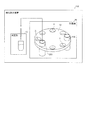
検体測定装置100は、検体に所定の1または複数種類の試薬を添加して、測定用試料を調製する。試薬は、ボトル状の試薬容器200に収容された状態で、検体測定装置100にセットされる。図1に示すように、検体測定装置100は、測定部10と、試薬庫20と、試薬容器ホルダ30とを備える。試薬庫20の試薬容器200に収められた試薬は、免疫検査に用いられる。たとえば、試薬は、抗原抗体反応を利用して検体中の目的物質と結合する捕捉物質、捕捉物質と結合する固相担体、抗原抗体反応を利用して目的物質と結合する標識物質、のいずれかを含む。
The
測定部10は、試薬を用いて検体を測定する。具体的には、測定部10は、試薬容器200の試薬を検体に添加して測定用試料を調整して、検体を測定する。また、測定部10は、検体および試薬により調製された測定用試料に含まれる成分を検出するように構成されている。測定部10による対象成分の検出方法は問わず、化学的方法、光学的方法、電磁気学的方法などの対象成分に応じた方法が採用できる。測定部10は、検出結果に基づいて、たとえば対象成分の有無、対象成分の数または量、対象成分の濃度や存在比率などを測定する。
The measuring
試薬庫20は、試薬が収められた試薬容器200を収容する。試薬庫20は、所定の温度に試薬を保冷または保温する。たとえば、試薬庫20は、試薬を所定の温度に保冷する。つまり、試薬庫20内の温度は、試薬庫20の外部の温度より低く保たれる。
The
試薬容器ホルダ30は、試薬庫20内に配置されている。また、試薬容器ホルダ30は、複数の試薬容器200を保持可能である。試薬容器ホルダ30は、試薬を収容する試薬容器200を吊り下げて保持する。具体的には、試薬容器ホルダ30は、試薬容器200を保持する複数の保持部31を有している。また、試薬容器ホルダ30には、検体測定装置100によって自動で、またはユーザによって手動で、試薬容器200がセットされる。また、試薬容器ホルダ30は、試薬容器200の所定箇所に設けられた係合部(図示せず)を試薬容器ホルダ30の支持する部分に引っかける態様で吊り下げて試薬容器200を保持してもよい。また、試薬容器ホルダ30は、水平に延びる扁平形状に形成されている。
The
これにより、試薬容器200を試薬容器ホルダ30により覆うことなく、試薬容器ホルダ30から試薬庫20内に突出して配置することができる。その結果、試薬容器200を試薬庫20内の空間に露出して配置することができるので、試薬の冷却効率または加熱効率を向上させることができる。これにより、試薬を効率よく保冷または保温することができる。また、試薬容器200ごとに箱状の小区画を設ける場合に比べて部品点数を減少させることができる。また、小区画を配置するスペースを削減することができるので、装置構成の簡素化および小型化を図ることができる。これらにより、試薬を効率よく保冷または保温するとともに部品点数の増加を抑制することができる。また、試薬容器ホルダ30により試薬容器200を吊り下げて保持することができるので、試薬容器200を安定して保持することができる。その結果、試薬容器200から試薬を吸引する際に、試薬容器200に吸引管を正しく挿入させることができる。
As a result, the
試薬容器ホルダ30は、平面視において、たとえば、円形形状を有している。また、試薬容器ホルダ30は、複数の試薬容器200を円周状に配置可能である。つまり、試薬容器ホルダ30の複数の保持部31は、円周状に配置されている。なお、試薬容器ホルダ30は、円形形状以外の形状を有していてもよい。たとえば、試薬容器ホルダ30は、平面視において、矩形形状に形成されていてもよい。また、複数の試薬容器200が直線状に配置されていてもよい。
The
また、試薬容器ホルダ30は、一重の円状に配列された複数の保持部31が設けられていてもよいし、二重の円状に配置された複数の保持部31が設けられていてもよい。また、試薬容器ホルダ30は、三重以上の円状に配列された複数の保持部31が設けられていてもよい。
Further, the
つぎに、本実施形態の検体測定装置100により実施される検体測定方法について簡単に説明する。試料測定方法は、以下のステップ(1)〜(2)を含む。
(1)試薬容器ホルダ30に、試薬が収容された試薬容器200を吊り下げて設置する。
(2)試薬庫20内の試薬を用いて検体を測定する。
Next, the sample measurement method implemented by the
(1) The
(2) The sample is measured using the reagent in the
本実施形態の検体測定方法では、上記のように、試薬容器ホルダ30に、試薬が収容された試薬容器200を吊り下げて設置する。これにより、試薬容器200が試薬容器ホルダ30により覆われることなく、試薬容器ホルダ30から試薬庫20内に突出して配置することができる。その結果、試薬容器200を試薬庫20内の空間に露出して配置することができるので、試薬の冷却効率または加熱効率を向上させることができる。これにより、試薬を効率よく保冷または保温することができる。また、試薬容器200ごとに箱状の小区画を設ける場合に比べて部品点数を減少させることができる。また、小区画を配置するスペースを削減することができるので、装置構成の簡素化および小型化を図ることができる。これらにより、試薬を効率よく保冷または保温するとともに装置の部品点数の増加を抑制することが可能な検体測定方法を提供することができる。
In the sample measurement method of the present embodiment, as described above, the
[検体測定装置の具体的な構成例]
次に、図2〜図17を参照して、検体測定装置100の具体的な構成例について詳細に説明する。図2〜図17の例では、検体測定装置100は、抗原抗体反応を利用して検体中の被検物質を検出する免疫測定装置である。
[Specific configuration example of sample measuring device]
Next, a specific configuration example of the
検体測定装置100は、測定部10と、試薬庫20と、試薬容器ホルダ30とを備える。また、図2の構成例では、検体測定装置100は、筐体110と、検体搬送部120と、検体分注部130と、反応容器供給部140と、反応容器移送部150と、反応部160と、試薬容器移送部170と、BF分離部180と、試薬分注部190とを備える。測定部10は、検出部11と、制御部12とを含む。
The
筐体110は、検体測定装置100の各部を内部に収容可能な箱状形状を有する。筐体110は、単一階層上に検体測定装置100の各部を収容する構成であってもよいし、上下方向に複数の階層が設けられた階層構造を有し、検体測定装置100の各部をそれぞれの階層に割り当てて配置してもよい。
The
検体搬送部120は、被検体から採取された検体を、検体分注部130による吸引位置まで搬送するように構成されている。検体搬送部120は、検体を収容した試験管が複数設置されたラックを所定の検体吸引位置まで搬送できる。
The
検体分注部130は、検体搬送部120により搬送された検体を吸引し、吸引した検体を反応容器40に分注する。検体分注部130は、吸引および吐出を行うための流体回路に接続されたピペットと、ピペットを移動させる移動機構とを含む。検体分注部130は、図示しないチップ供給部にセットされた分注チップをピペットの先端に装着して、搬送された試験管中の検体を分注チップ内に所定量吸引する。検体分注部130は、吸引した検体を所定の検体分注位置に配置された反応容器40に分注する。分注後、検体分注部130は、分注チップをピペットの先端から取り外して廃棄する。
The
反応容器供給部140は、複数の反応容器40を貯留している。反応容器供給部140は、所定の反応容器供給位置において、反応容器移送部150に反応容器40を1つずつ供給できる。
The reaction
反応容器移送部150は、反応容器40を移送する。反応容器移送部150は、反応容器供給位置から反応容器40を取得し、検体分注部130、試薬分注部190、反応部160、検出部11などの各々の処理位置に反応容器40を移送する。反応容器移送部150は、たとえば反応容器40を把持するキャッチャまたは反応容器40の設置穴を有する保持部と、キャッチャまたは保持部を移動させる移動機構とにより構成される。移動機構は、たとえば1または複数の直線移動可能な直動機構により、1軸または複数軸方向に移動する。移動機構は、回転軸回りに水平回転するアーム機構や、多関節ロボット機構を含んでいてもよい。反応容器移送部150は、1つまたは複数設けられる。
The reaction
反応部160は、ヒーターおよび温度センサを備え、反応容器40を保持して反応容器40に収容された試料を加温して反応させる。加温により、反応容器40内に収容された検体および試薬が反応する。反応部160は、筐体110内に1つまたは複数設けられる。反応部160は、筐体110に固定的に設置されていてもよいし、筐体110内で移動可能に設けられていてもよい。反応部160が移動可能に構成される場合、反応部160は、反応容器移送部150の一部としても機能しうる。
The
試薬容器移送部170は、試薬容器200を移送することができる。たとえば、試薬容器移送部170は、図示しないハンド機構により試薬容器200を持ち上げ、試薬容器ホルダ30の保持部31にそれぞれセットできる。
The reagent
BF分離部180は、反応容器40から、液相と固相とを分離するBF分離処理を実行する機能を有する。BF分離部180は、それぞれ反応容器40を設置可能な処理ポートを1つまたは複数含む。処理ポートには、R2試薬に含まれる磁性粒子を集磁するための磁力源182(図16参照)と、液相の吸引および洗浄液の供給を行うための洗浄部181(図16参照)とが設けられている。BF分離部180は、後述する免疫複合体が形成された磁性粒子を集磁した状態で、洗浄部181により反応容器40内の液相を吸引して洗浄液を供給する。洗浄部181は、液相の吸引通路と洗浄液の吐出通路とを備え、図示しない流体回路に接続されている。これにより、液相に含まれる不要な成分を免疫複合体と磁性粒子との結合体から分離して除去できる。
The
試薬分注部190は、試薬容器200内の試薬を吸引し、吸引した試薬を反応容器40に分注する。試薬分注部190は、試薬の吸引および吐出を行うための吸引管190aを、試薬吸引位置と、試薬分注位置との間で水平方向に移動できる。また、試薬分注部190は、吸引管190aを下方向に移動させ、試薬容器200の内部に進入させることができる。また、試薬分注部190は、吸引管190aを下方向に移動させ、試薬容器200の上方位置まで吸引管190aを退避させることができる。吸引管190aは、図示しない流体回路と接続され、試薬容器200から所定量の試薬を吸引し、試薬分注位置に移送された反応容器40に試薬を分注する。
The
吸引管190aは、液面センサに接続されている。液面センサは、制御部12に接続されており、試薬容器200から試薬を吸引する際、試薬の液面と吸引管190aとの接触による静電容量の変化に基づいて試薬液面を検知して、検知結果を制御部12に出力する。また、制御部12は、試薬分注部190の動作量を監視することによって、吸引管190aの上下方向の移動量を監視する。
The
試薬分注部190は、たとえば、R1試薬〜R3試薬の各々の分注用に、3つ設けられる。1つの試薬分注部190によって、複数種類の試薬を分注してもよい。図2に示した構成例では、試薬分注部190は、R1試薬を分注するための第1試薬分注部191と、R2試薬を分注するための第2試薬分注部192と、R3試薬を分注するための第3試薬分注部193と、を含む。また、試薬分注部190は、R4試薬を分注するための第4試薬分注部194およびR5試薬を分注するための第5試薬分注部195を含む。
Three
第1試薬分注部191は、R1試薬を吸引するための最も内周側の孔部21dと、所定のR1試薬分注位置との間で吸引管190aを移動できる。第2試薬分注部192は、R2試薬を吸引するための最も外周側の孔部21dと、所定のR2試薬分注位置との間で吸引管190aを移動できる。第3試薬分注部193は、R3試薬を吸引するための径方向中間位置の孔部21dと、所定のR3試薬分注位置との間で吸引管190aを移動できる。第4試薬分注部194および第5試薬分注部195は、それぞれR4試薬およびR5試薬を収容した試薬容器(図示せず)と送液チューブを介して接続されており、反応容器移送部150によって移送された反応容器40中に試薬を吐出できる。
The first
検出部11は、光電子増倍管などの光検出器11a(図16参照)を含む。検出部11は、各種処理が行なわれた検体の抗原に結合する標識抗体と発光基質との反応過程で生じる光を光検出器11aで取得することにより、その検体に含まれる抗原の量を測定する。
The
制御部12は、CPUなどのプロセッサ12aと、ROM、RAMおよびハードディスクなどの記憶部12bとを含む。プロセッサ12aは、記憶部12bに記憶された制御プログラムを実行することにより、検体測定装置100の制御部として機能する。制御部12は、上述した検体測定装置100の各部の動作を制御する。また、制御部12は、検出部11により検出した結果を測定する。
The
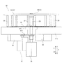
図2の構成例では、検体測定装置100は、試薬容器ホルダ30を収容する箱状の試薬庫20を備える。図3に示すように、試薬容器ホルダ30は、試薬庫20の断熱機能を有するケース21内に設けられている。試薬庫20は、ケース21内に試薬容器ホルダ30と冷却機構22とを有し、試薬容器ホルダ30にセットされた試薬容器200内の試薬を保管に適した一定温度に保冷する。また、試薬庫20は、試薬容器200を複数収容させるように、試薬容器ホルダ30を試薬庫20内に配置する。
In the configuration example of FIG. 2, the
ケース21は、円形状のカバー21aおよび底面部21bと、円筒状の側面部21cとにより区画された内部空間を有する。カバー21a、底面部21bおよび側面部21cは、断熱材を含んでおり、ケース21の内部と外部とを断熱する。たとえば、カバー21a、底面部21bおよび側面部21cは、発砲材料を含んでいる。これにより、試薬容器200を冷温保管することができる。
The
カバー21aは、試薬容器(200)の上部を覆う。カバー21aは、円板形状を有している。また、カバー21aは、試薬庫20の外周よりも大きい外周を有する。これにより、カバー21aにより試薬庫20の上部を確実に覆うことができるので、試薬庫20に収容された複数の試薬容器200をより効率よく保冷または保温することができる。
The
試薬庫20は、試薬分注部190が試薬庫20の内部へ進入するための孔部21dを有する。孔部21dは、カバー21aに設けられている。また、孔部21dは、複数設けられている。
The
冷却機構22は、たとえば、ペルチェ素子などを含む冷却部と、熱を伝えるフィンとを含む。また、冷却機構22は、試薬庫20の底面部21b付近に複数設けられている。冷却機構22には、ファンにより試薬庫20内の空気が送られて、冷却された空気が試薬庫20内を循環される。
The
試薬容器ホルダ30は、複数の試薬容器200を保持することができる。試薬容器ホルダ30は、複数の保持部31を含む。具体的には、試薬容器ホルダ30は、試薬容器200を吊り下げて保持する吊り下げ部32を含む。また、試薬容器ホルダ30は、貫通口33を含む。また、試薬容器ホルダ30は、複数の試薬容器200を円周方向に並べて保持するように形成されている。図3の構成例では、試薬容器ホルダ30は、第1試薬容器ホルダ34と、第2試薬容器ホルダ35とを含む。また、試薬容器ホルダ30は、第1試薬容器ホルダ34を回転させる第1駆動部36と、第2試薬容器ホルダ35を回転させる第2駆動部37とを含む。また、試薬容器ホルダ30は、回転テーブル38と、連結部材39とを含む。
The
ここで、図3および図4に示すように、試薬容器ホルダ30は、水平に延びる扁平形状に形成されている。これにより、試薬を効率よく保冷または保温するとともに部品点数の増加を抑制することができる。
Here, as shown in FIGS. 3 and 4, the
具体的には、試薬容器ホルダ30は、試薬容器200の表面の50%以上が試薬庫20内の空間に露出するように試薬容器200を保持するように構成されている。これにより、試薬容器200の表面の50%以上を試薬庫20内の空間に露出して配置することができるので、試薬の冷却効率または加熱効率をより向上させることができる。
Specifically, the
より好ましくは、試薬容器ホルダ30は、試薬容器200の表面の80%以上が試薬庫20内の空間に露出するように試薬容器200を保持するように構成されている。これにより、試薬容器200の表面の80%以上を試薬庫20内の空間に露出して配置することができるので、試薬の冷却効率または加熱効率を効果的に向上させることができる。
More preferably, the
たとえば、試薬容器ホルダ30は、吊り下げ部32により、試薬容器200を吊り下げて保持する。これにより、試薬容器ホルダ30により試薬容器200の上方部分を支持することができるので、試薬が溜まっている試薬容器200の下方部分を試薬庫20内に確実に露出させることができる。また、試薬容器200の上方部分を支持することができるので、上方から試薬を吸引する場合に安定して試薬容器200を保持することができる。
For example, the
また、試薬容器ホルダ30は、隣接する試薬容器200の露出部分が互いに対向するように複数の試薬容器200を保持するように構成されている。つまり、隣接する試薬容器200の間の空間は、扁平形状の試薬容器ホルダ30が支持する高さ位置以外の部分は、試薬庫20内に開放されている。これにより、隣接する試薬容器200の間に部材が配置されないため、複数の試薬容器200の距離を近づけることができる。これにより、試薬容器200を配置するスペースを小さくすることができるので、装置を効果的に小型化することができる。
Further, the
図3〜図5に示すように、試薬容器ホルダ30は、複数の試薬容器200が円周状に配置されるように構成されているとともに、略円形の外周縁を有する。これにより、複数の試薬容器200を略円形の試薬容器ホルダ30に円周状に配置してコンパクトに保管庫内に収容することができる。また、試薬容器ホルダ30の第1試薬容器ホルダ34は、円形状に形成されている。また、第2試薬容器ホルダ35は、平面視において、第1試薬容器ホルダ34を取り囲むように円環状に形成されている。つまり、第2試薬容器ホルダ35は、第1試薬容器ホルダ34の周囲に配置されている。第1試薬容器ホルダ34と第2試薬容器ホルダ35とは、同心状に配置されていて、互いに独立して回転できる。また、第1試薬容器ホルダ34と第2試薬容器ホルダ35とは、略同じ高さ位置に配置されている。
As shown in FIGS. 3 to 5, the
内周側の第1試薬容器ホルダ34は、円周状に複数の試薬容器200を保持できる。外周側の第2試薬容器ホルダ35は、円周状に複数の試薬容器200を保持できる。
The first
試薬容器ホルダ30は、保持部31により、試薬容器200を位置決めして固定する。これにより、試薬容器200を、試薬容器ホルダ30の所定の位置に精度よく配置することができるとともに、試薬容器200が試薬容器ホルダ30に対して移動するのを抑制することができる。
The
図3および図4の構成例では、試薬容器ホルダ30は、上下方向(Z方向)において試薬庫20の上半分側の領域に配置されている。これにより、試薬容器ホルダ30により試薬容器200の上半分の部分を支持することができるので、試薬が溜まっている試薬容器200の下方部分を試薬庫20内に確実に露出させることができる。また、試薬容器200の上半分の部分を支持することができるので、上方から試薬を吸引する場合に安定して試薬容器200を保持することができる。
In the configuration examples of FIGS. 3 and 4, the
図6に示すように、第1駆動部36は、試薬庫20の外側に配置されている。具体的には、第1駆動部36は、試薬庫20の下方の外側に配置されている。第1駆動部36は、第1支持部361を回転させる。第1支持部361は、第1試薬容器ホルダ34を支持している。つまり、第1駆動部36は、第1支持部361を介して、第1試薬容器ホルダ34を回転駆動させる。第1駆動部36は、たとえばステッピングモータやサーボモータなどの駆動源である。具体的には、第1駆動部36は、第1試薬容器ホルダ34の中心に接続され上下に延びる第1支持部361を回転駆動することにより、第1試薬容器ホルダ34を回転させる。第1支持部361は、下端部が第1駆動部36に連結され、上端部が第1試薬容器ホルダ34の中心に連結されている。
As shown in FIG. 6, the
これにより、試薬庫20の外側に配置された第1駆動部36により、第1試薬容器ホルダ34を容易に回転移動させることができる。また、第1駆動部36を試薬庫20の外に設けることにより、第1駆動部36が第1試薬容器ホルダ34に保持された試薬容器200に干渉するのを抑制することができるとともに、第1駆動部36の熱が試薬庫20内に伝達されるのを抑制することができる。
As a result, the first
第2駆動部37は、試薬庫20の外側に配置されている。具体的には、第2駆動部37は、試薬庫20の下方の外側に配置されている。第2駆動部37は、第2支持部371を回転させる。第2支持部371は、回転テーブル38を支持している。回転テーブル38は、複数の連結部材39を介して第2試薬容器ホルダ35を支持している。つまり、第2駆動部37は、第2支持部371、回転テーブル38および連結部材39を介して、第2試薬容器ホルダ35を回転駆動させる。第2駆動部37は、たとえばステッピングモータやサーボモータなどの駆動源である。具体的には、第2駆動部37は、伝達機構372を介して第2試薬容器ホルダ35に連結された回転テーブル38を回転駆動することにより、第2試薬容器ホルダ35を回転させる。回転テーブル38は、カップリングおよび第2支持部371を介して、伝達機構372に連結されている。回転テーブル38および第2支持部371は、中央に第1支持部361を通す貫通孔が設けられており、第1支持部361とは独立して回転する。これにより、第2駆動部37と、第1駆動部36とが、それぞれ、外周側の第2試薬容器ホルダ35と、内周側の第1試薬容器ホルダ34とを独立して回転駆動させる。
The
これにより、第1試薬容器ホルダ34とは独立して第2試薬容器ホルダ35を回転移動させることができる。また、第2駆動部37を試薬庫20の外に設けることにより、第2駆動部37が第2試薬容器ホルダ35に保持された試薬容器200に干渉するのを抑制することができるとともに、第2駆動部37の熱が試薬庫20内に伝達されるのを抑制することができる。
As a result, the second
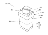
試薬容器200は、試薬容器201と、試薬容器202とを含む。図7および図8に示す各構成例では、試薬容器201は、後述するR2試薬を収容する容器本体232を含む。試薬容器202は、後述するR3試薬を収容する容器本体233と、R1試薬を収容する容器本体231とが、1組に連結された多連タイプの試薬容器である。
The
試薬容器201および試薬容器202は、それぞれ、容器本体の上部を覆う上部カバー240を備える。上部カバー240は、容器本体の側面の一部を覆うように容器本体の側面に沿う外周部241を有し、外周部241の下端部に、試薬容器ホルダ30と係合するための当接部242が設けられている。当接部242は、試薬容器ホルダ30の保持部31に支持される。当接部242は、試薬容器ホルダ30に当接する。また、当接部242は、容器本体の外周よりも大きい外周を有する。図7および図8の構成例において、上部カバー240は、被把持部243を有する。また、上部カバー240には、開閉可能な蓋部220が設けられている。
Each of the
図3の構成例において、円周方向に並べて保持された複数の試薬容器201の各々の蓋部220は、同一円周状に並んで配置されている。円周方向に並べて保持された複数の試薬容器202の各々の試薬容器202は、同一円周状に並んで配置されている。円周方向に並べて保持された複数の試薬容器202の各々の容器本体231、233は、それぞれ同一円周状に並んで配置されている。試薬容器ホルダ30において、容器本体232、容器本体233、容器本体231の各々は、半径方向の異なる位置に配置されている。そのため、図2に示したように、ケース21のカバー21aには、R1試薬〜R3試薬のそれぞれの吸引位置に対応する孔部21dが、対応する試薬容器200の蓋部220が配列された円周上の所定位置に重なるように、3箇所に設けられている。
In the configuration example of FIG. 3, the
試薬容器ホルダ30の貫通口33は、試薬容器200が挿入されて設置される。具体的には、試薬容器ホルダ30は、貫通口33を有する板状部材30aを含む。また、板状部材30aは、試薬容器200の底面251を貫通口33から露出させるように、試薬容器200を保持する。これにより、試薬容器200を板状部材30aの貫通口33から挿入して試薬容器200を容易に試薬容器ホルダ30に設置することができる。また、板状部材30aは、試薬容器200を吊り下げて保持する吊り下げ部(32)を複数含む。また、吊り下げ部32は、下方に向かって先細る形状を有する。
The through-
図9〜図12に示すように、試薬容器200は、試薬容器ホルダ30の貫通口33を通過可能な底面251と、底面から上面の間において貫通口33の外周よりも大きい外周を有する中間側面部252とを含む。これにより、試薬容器200を試薬容器ホルダ30の貫通口33から挿入して試薬容器200を容易に試薬容器ホルダ30に設置することができる。また、試薬容器200の中間側面部252を試薬容器ホルダ30の貫通口33の縁部に当接させることができるので、試薬容器200の上下方向を精度よく位置決めして設置することができる。つまり、試薬容器200を試薬容器ホルダ30に対してがたつくことなくセットすることができる。また、試薬容器200を試薬容器ホルダ30に対して容易にセットすることができる。
As shown in FIGS. 9 to 12, the
図9に示す例では、試薬容器ホルダ30の貫通口33は、下段開口33aと、下段開口33aの上方に設けられ下段開口33aの外周より大きい外周を有する上段開口33bとを含む。つまり、吊り下げ部32は、下段開口33aと、下段開口33aの上方に設けられ下段開口33aの外周より大きい外周を有する上段開口(33b)とを含む。また、試薬容器200の底面251は、下段開口33aより小さい外周を有し、試薬容器200の中間側面部252は、上段開口33bと略同一の大きさの外周を有する。これにより、上段開口33bの外周が試薬容器200の底面251の外周よりも大きいので、図9(A)に示すように、試薬容器200を容易に上段開口33bに挿入することができる。また、上段開口33bから挿入された試薬容器200を上段開口33bに続く下段開口33aに容易に導くことができるので、試薬容器200を容易に下段開口33aに挿入することができる。また、上段開口33bの外周が試薬容器200の中間側面部252の外周と略同一の大きさであるので、図9(B)に示すように、中間側面部252を上段開口33bに嵌り込ませることにより、試薬容器200を試薬容器ホルダ30に対して容易に固定することができる。
In the example shown in FIG. 9, the through-
下段開口33aと、試薬容器200との間の隙間は、たとえば、片側につき1mm〜2mm程度である。また、上段開口333bと、試薬容器200との間の隙間は、たとえば、片側につき、0.1mm程度である。
The gap between the
また、貫通口33は、一部のみあそびを有していてもよい。たとえば、貫通口33は、角部付近において、試薬容器200との間の隙間が大きくなっていてもよい。これにより、寸法誤差により試薬容器200が貫通口33に入らなくなることを抑制することが可能である。
Further, the through-
図10に示す例では、上段開口33bは、下段開口33aに向かって先細るテーパ形状を有する。これにより、上段開口33bから下段開口33aに試薬容器200をより容易に導くことができるので、試薬容器200を試薬容器ホルダ30に容易に設置することができる。つまり、図10(A)に示すように、上段開口33bのテーパ形状により、試薬容器200が貫通口33の中央に向けて導かれる。そして、図10(B)に示すように、試薬容器200の中間側面部252が上段開口33bに嵌り込んで位置決めされる。
In the example shown in FIG. 10, the
上段開口33bのテーパ形状は、たとえば、垂直方向に対して、15度〜60度程度の傾斜角度を有している。
The tapered shape of the
試薬容器200は、図11に示すように、側面が上方に向かって広がるように傾斜していてもよい。これにより、底面251が貫通口33を通過し、所定の高さ位置において、中間側面部252が貫通口33に隙間なく嵌りんで、試薬容器200が設置される。また、試薬容器200は、図12に示すように、中間側面部252が側面から突出して設けられていてもよい。
As shown in FIG. 11, the
また、試薬容器200は、図13に示すように、係合部260を有していてもよい。この場合、試薬容器ホルダ30は、支持部301と、被係合部302とを有していてもよい。試薬容器200は、係合部260が被係合部302に係合し、引掛けられることにより、試薬容器ホルダ30に保持される。
Further, the
試薬容器ホルダ30は、図14に示すように、試薬容器200の上方の部分を支持してもよい。また、試薬容器ホルダ30は、図15に示すように、試薬容器200の上下方向における中央部付近の部分を支持してもよい。
The
(免疫測定の概要)
図2〜図15に示した構成例では、上記の通り、R1試薬〜R5試薬を用いて免疫測定が行われる。図16を参照して、免疫測定の一例として、被検物質81がB型肝炎表面抗原(HBsAg)である例について説明する。
(Outline of immunoassay)
In the configuration examples shown in FIGS. 2 to 15, immunoassay is performed using the R1 reagent to the R5 reagent as described above. As an example of immunoassay, an example in which the
まず、反応容器40に被検物質81を含む検体とR1試薬とが分注される。第1試薬分注部191により、R1試薬が反応容器40中に分注され、検体分注部130により、反応容器40中に検体が分注される。R1試薬は、捕捉物質84を含有し、被検物質81と反応して結合する。捕捉物質84は、捕捉物質84がR2試薬に含まれる固相担体82と結合するための結合物質を含む。
First, the sample containing the
この結合物質と固相担体との結合には、たとえばビオチンとアビジン類、ハプテンと抗ハプテン抗体、ニッケルとヒスタチジンタグ、グルタチオンとグルタチオン−S−トランスフェラーゼなどの組み合わせが利用できる。なお、「アビジン類」とは、アビジンおよびストレプトアビジンを含むことを意味する。 For binding of this binding substance to the solid phase carrier, for example, a combination of biotin and avidins, hapten and anti-hapten antibody, nickel and histatisin tag, glutathione and glutathione-S-transferase can be used. In addition, "avidins" means that avidin and streptavidin are included.
たとえば、捕捉物質84は、ビオチンで修飾された抗体(biotin抗体)である。すなわち、捕捉物質84には、結合物質としてビオチンが修飾されている。検体とR1試薬との分注後、反応部160において反応容器40内の試料が所定温度に加温されることにより、捕捉物質84と被検物質81とが結合する。
For example, capture
次に、第2試薬分注部192により、反応容器40にR2試薬が分注される。R2試薬は、固相担体82を含有する。固相担体82は、捕捉物質84の結合物質と結合する。固相担体82は、たとえばビオチンと結合するストレプトアビジンを固定した磁性粒子(StAvi結合磁性粒子)である。StAvi結合磁性粒子のストレプトアビジンは、結合物質であるビオチンと反応して結合する。R2試薬の分注後、反応部160において反応容器40内の試料が所定温度に加温される。この結果、被検物質81と捕捉物質84とが、固相担体82と結合する。
Next, the R2 reagent is dispensed into the
固相担体82上に形成された被検物質81および捕捉物質84と、未反応の捕捉物質84とは、BF分離部180による1次BF分離処理によって分離される。BF分離部180の処理ポートに反応容器40がセットされると、BF分離部180は、磁力源182による集磁状態での洗浄部181による液相の吸引と、洗浄液の吐出と、非集磁状態での攪拌と、の各工程を1または複数回実行する。1次BF分離処理によって、未反応の捕捉物質84などの不要成分が、反応容器40中から除去される。1次BF分離処理では、最終的に反応容器40内の液相が吸引された状態で、次の工程に進む。
The
次に、第3試薬分注部193により、反応容器40にR3試薬が分注される。R3試薬は、標識物質83を含有し、被検物質81と反応して結合する。R3試薬の分注後、反応部160において反応容器40内の試料が所定温度に加温される。この結果、固相担体82上に、被検物質81と、標識物質83と、捕捉物質84とを含む免疫複合体85が形成される。図16の例では、標識物質83は、ALP(アルカリホスファターゼ)標識抗体である。
Next, the R3 reagent is dispensed into the
固相担体82上に形成された免疫複合体85と、未反応の標識物質83とは、2次BF分離処理によって分離される。BF分離部180は、磁力源182による集磁状態での液相の吸引と、洗浄液の吐出と、非集磁状態での攪拌と、の各工程を1または複数回実行する。2次BF分離処理によって、未反応の標識物質83などの不要成分が、反応容器40中から除去される。2次BF分離処理では、最終的に反応容器40内の液相が吸引された状態で、次の工程に進む。
The immune complex 85 formed on the solid-
その後、第4試薬分注部194および第5試薬分注部195の各々により、反応容器40にR4試薬およびR5試薬が分注される。R4試薬は、緩衝液を含有する。固相担体82と結合した免疫複合体85が緩衝液中に分散される。R5試薬は、化学発光基質を含有する。R4試薬に含有される緩衝液は、免疫複合体85に含まれる標識物質83の標識(酵素)と基質との反応を促進する組成を有する。R4、R5試薬の分注後、反応部160において反応容器40内の試料が所定温度に加温される。標識に対して基質を反応させることによって光が発生し、発生する光の強度が検出部11の光検出器11aにより測定される。制御部12は、検出部11の検出信号に基づいて、検体中の被検物質81の含有量などを測定する。
Then, the R4 reagent and the R5 reagent are dispensed into the
(測定処理動作の説明)
次に、図16に示した検体測定装置100の測定処理動作を、図17を用いて説明する。また、図17に示す各ステップの処理は、制御部12によって制御される。
(Explanation of measurement processing operation)
Next, the measurement processing operation of the
ステップS1において、制御部12は、反応容器移送部150に反応容器40をR1試薬分注位置に移送させる。制御部12は、第1試薬分注部191に、反応容器40内にR1試薬を分注させる。
In step S1, the
ステップS2において、反応容器40に検体が分注される。制御部12は、検体分注部130により検体搬送部120上の試験管から検体を吸引させる。制御部12は、検体分注部130により、吸引した検体を反応容器40に分注させる。分注後、検体分注部130は、図示しない廃棄口に分注チップを廃棄するように制御される。検体分注部130は、分注チップを介した分注動作を行う度に、未使用の分注チップに交換する。
In step S2, the sample is dispensed into the
ステップS3において、制御部12は、反応容器移送部150により反応容器40をR2試薬分注位置に移送させ、第2試薬分注部192により反応容器40にR2試薬を分注させる。R2試薬の分注後、制御部12は、反応容器移送部150により、反応部160に反応容器40を移送させる。反応容器40は、反応部160において所定時間の間加温される。
In step S3, the
ステップS4において、制御部12は、BF分離部180に1次BF分離処理を実行させる。まず、制御部12は、反応容器移送部150により反応容器40をBF分離部180に移送させる。BF分離部180は、反応容器40中の試料に対して1次BF分離処理(図16参照)を行い、液体成分を除去するように制御される。
In step S4, the
ステップS5において、制御部12は、反応容器移送部150により反応容器40をR3試薬分注位置に移送し、第3試薬分注部193により反応容器40にR3試薬を分注させる。R3試薬の分注後、制御部12は、反応容器移送部150により、反応部160に反応容器40を移送させる。反応容器40は、反応部160において所定時間の間加温される。
In step S5, the
ステップS6において、制御部12は、BF分離部180に2次BF分離処理を実行させる。まず、制御部12は、反応容器移送部150により反応容器40をBF分離部180に移送させる。BF分離部180は、反応容器40中の試料に対して2次BF分離処理(図16参照)を行い、液体成分を除去するように制御される。
In step S6, the
ステップS7において、反応容器40にR4試薬が分注される。制御部12は、反応容器移送部150により反応容器40をR4試薬分注位置に移送させ、第4試薬分注部194により、反応容器40にR4試薬を分注させる。
In step S7, the R4 reagent is dispensed into the
ステップS8において、反応容器40にR5試薬が分注される。制御部12は、反応容器移送部150により反応容器40をR5試薬分注位置に移送させ、第5試薬分注部195により、反応容器40にR5試薬を分注させる。R5試薬の分注後、制御部12は、反応容器移送部150により、反応部160に反応容器40を移送させる。反応容器40は、反応部160において所定時間の間加温される。
In step S8, the R5 reagent is dispensed into the
ステップS9において、免疫複合体85の検出処理が行われる。制御部12は、反応容器移送部150により反応容器40を検出部11に移送させる。検出部11により、標識に対して基質を反応させることによって生じる光の強度が測定される。検出部11の検出結果は、制御部12に出力される。
In step S9, the detection process of the immune complex 85 is performed. The
検出終了後は、ステップS10において、反応容器移送部150が、測定処理済みの反応容器40を検出部11から取り出して、図示しない廃棄口に廃棄するように制御される。
After the detection is completed, in step S10, the reaction
以上により、検体測定装置100による測定処理動作が行われる。
As described above, the measurement processing operation by the
なお、今回開示された実施形態は、すべての点で例示であって制限的なものではないと考えられるべきである。本発明の範囲は、上記した実施形態の説明ではなく特許請求の範囲によって示され、さらに特許請求の範囲と均等の意味および範囲内でのすべての変更が含まれる。 It should be noted that the embodiments disclosed this time are exemplary in all respects and are not considered to be restrictive. The scope of the present invention is shown by the scope of claims rather than the description of the above-described embodiment, and further includes all modifications within the meaning and scope equivalent to the scope of claims.
10:測定部、20:試薬庫、21a:カバー、30:試薬容器ホルダ、30a:板状部材、31:保持部、32:吊り下げ部、33:貫通口、33a:下段開口、33b:上段開口、34:第1試薬容器ホルダ、35:第2試薬容器ホルダ、36:第1駆動部、37:第2駆動部、38:回転テーブル、39:連結部材、100:検体測定装置、200:試薬容器、231、232、233:容器本体、242:当接部、251:底面、361:第1支持部、371:第2支持部
10: Measuring part, 20: Reagent storage, 21a: Cover, 30: Reagent container holder, 30a: Plate-shaped member, 31: Holding part, 32: Hanging part, 33: Through port, 33a: Lower opening, 33b: Upper stage Opening, 34: 1st reagent container holder, 35: 2nd reagent container holder, 36: 1st drive unit, 37: 2nd drive unit, 38: rotary table, 39: connecting member, 100: sample measuring device, 200:
Claims (25)
前記試薬容器ホルダに保持された前記試薬容器に収容された試薬を冷却する冷却機構と、
前記試薬を用いて検体を測定する測定部と、を備え、
前記試薬容器ホルダは、前記容器本体を囲む形状の貫通口を有する板状部材を含み、
前記板状部材は、前記容器本体を前記貫通口から露出させ、前記貫通口の周縁に前記当接部を当接させた状態で前記試薬容器を保持する、検体測定装置。 A reagent container having a contact portion and the container body for containing a reagent to surround the outer periphery of the container body, the reagent container holder for holding hanging,
A cooling mechanism for cooling the reagent contained in the reagent container held in the reagent container holder,
A measuring unit for measuring a sample using the reagent is provided .
The reagent container holder includes a plate-shaped member having a through hole shaped to surround the container body.
The plate-like member, the container body is exposed from the through-hole, that holds the reagent containers in a state where said contact portion is in contact with the periphery of the through hole, the analyte measuring device.
前記第1試薬容器ホルダを支持する第1支持部と、
前記第1支持部を回転させる第1駆動部とを備える、請求項1〜7のいずれか1項に記載の検体測定装置。 The reagent container holder includes a first reagent container holder.
A first support portion that supports the first reagent container holder and
The sample measuring device according to any one of claims 1 to 7, further comprising a first driving unit that rotates the first support unit.
連結部材を介して前記第2試薬容器ホルダを支持する回転テーブルと、
前記回転テーブルを支持する第2支持部と、
前記第2支持部を回転させる第2駆動部とを備える、請求項8に記載の検体測定装置。 The reagent container holder includes a second reagent container holder arranged around the first reagent container holder.
A rotary table that supports the second reagent container holder via a connecting member, and
A second support portion that supports the rotary table and
The sample measuring device according to claim 8, further comprising a second driving unit that rotates the second support unit.
前記試薬庫は、前記試薬容器を複数収容させるように、前記試薬容器ホルダを前記試薬庫内に配置する、請求項1〜9のいずれか1項に記載の検体測定装置。 A reagent storage including a cover covering the upper part of the reagent container is provided.
The sample measuring device according to any one of claims 1 to 9, wherein the reagent container holder is arranged in the reagent container so as to accommodate a plurality of the reagent containers.
前記試薬容器の容器本体を囲む形状の前記貫通口から前記容器本体を露出させるように、前記貫通口の周縁に前記当接部を当接させた状態で前記試薬容器を保持し、
前記試薬容器ホルダに保持された前記試薬容器に収容された試薬を冷却し、
前記試薬を用いて検体を測定する、検体測定方法。 The reagent container holder comprising a plate-like member having a through hole, a reagent container having a contact portion surrounding the outer periphery of the container body and the container body for containing a reagent is installed suspended,
The reagent container is held in a state where the contact portion is in contact with the peripheral edge of the through port so that the container body is exposed from the through port having a shape surrounding the container body of the reagent container .
The reagent contained in the reagent container held in the reagent container holder is cooled, and the reagent is cooled.
A sample measurement method for measuring a sample using the reagent.
前記容器本体を囲む形状の貫通口を有する板状部材を含む試薬容器ホルダに当接するとともに、前記容器本体の外周を取り囲む当接部と、を備え、
前記容器本体が前記貫通口から露出するように、前記当接部が前記貫通口の周縁に当接した状態で前記試薬容器ホルダに吊り下げられて保持され、前記容器本体に収容された試薬が冷却機構により冷却される、試薬容器。 The main body of the container that houses the reagents used for sample measurement,
It is provided with a contact portion that abuts on a reagent container holder including a plate-shaped member having a through-hole having a shape that surrounds the container body and that surrounds the outer periphery of the container body.
The reagent contained in the container body is suspended and held by the reagent container holder in a state where the contact portion is in contact with the peripheral edge of the through port so that the container body is exposed from the through port. A reagent container that is cooled by a cooling mechanism.
底面から上面の間において前記貫通口の外周よりも大きい外周を有する中間側面部とを備える、請求項21に記載の試薬容器。 The bottom surface of the reagent container holder that can pass through the through port, and
The reagent container according to claim 21, further comprising an intermediate side surface portion having an outer circumference larger than the outer circumference of the through-hole between the bottom surface and the upper surface.
Priority Applications (7)
| Application Number | Priority Date | Filing Date | Title |
|---|---|---|---|
| JP2018010309A JP6959875B2 (en) | 2018-01-25 | 2018-01-25 | Specimen measuring device, reagent container and sample measuring method |
| PCT/JP2018/045089 WO2019146272A1 (en) | 2018-01-25 | 2018-12-07 | Specimen measurement device, reagent container, and specimen measurement method |
| EP18902344.3A EP3745136A4 (en) | 2018-01-25 | 2018-12-07 | Specimen measurement device, reagent container, and specimen measurement method |
| CN201880087710.9A CN111630394A (en) | 2018-01-25 | 2018-12-07 | Sample measurement device, reagent container, and sample measurement method |
| US16/937,769 US20200355713A1 (en) | 2018-01-25 | 2020-07-24 | Sample measuring apparatus, reagent container, and method of measuring sample |
| JP2021163242A JP7186272B2 (en) | 2018-01-25 | 2021-10-04 | Specimen measuring device and specimen measuring method |
| JP2022189110A JP7357750B2 (en) | 2018-01-25 | 2022-11-28 | reagent container |
Applications Claiming Priority (1)
| Application Number | Priority Date | Filing Date | Title |
|---|---|---|---|
| JP2018010309A JP6959875B2 (en) | 2018-01-25 | 2018-01-25 | Specimen measuring device, reagent container and sample measuring method |
Related Child Applications (1)
| Application Number | Title | Priority Date | Filing Date |
|---|---|---|---|
| JP2021163242A Division JP7186272B2 (en) | 2018-01-25 | 2021-10-04 | Specimen measuring device and specimen measuring method |
Publications (2)
| Publication Number | Publication Date |
|---|---|
| JP2019128265A JP2019128265A (en) | 2019-08-01 |
| JP6959875B2 true JP6959875B2 (en) | 2021-11-05 |
Family
ID=67395317
Family Applications (3)
| Application Number | Title | Priority Date | Filing Date |
|---|---|---|---|
| JP2018010309A Active JP6959875B2 (en) | 2018-01-25 | 2018-01-25 | Specimen measuring device, reagent container and sample measuring method |
| JP2021163242A Active JP7186272B2 (en) | 2018-01-25 | 2021-10-04 | Specimen measuring device and specimen measuring method |
| JP2022189110A Active JP7357750B2 (en) | 2018-01-25 | 2022-11-28 | reagent container |
Family Applications After (2)
| Application Number | Title | Priority Date | Filing Date |
|---|---|---|---|
| JP2021163242A Active JP7186272B2 (en) | 2018-01-25 | 2021-10-04 | Specimen measuring device and specimen measuring method |
| JP2022189110A Active JP7357750B2 (en) | 2018-01-25 | 2022-11-28 | reagent container |
Country Status (5)
| Country | Link |
|---|---|
| US (1) | US20200355713A1 (en) |
| EP (1) | EP3745136A4 (en) |
| JP (3) | JP6959875B2 (en) |
| CN (1) | CN111630394A (en) |
| WO (1) | WO2019146272A1 (en) |
Family Cites Families (17)
| Publication number | Priority date | Publication date | Assignee | Title |
|---|---|---|---|---|
| JPH0250681U (en) * | 1988-09-30 | 1990-04-09 | ||
| JPH0721220Y2 (en) * | 1990-02-08 | 1995-05-17 | 三井製薬工業株式会社 | Stirrer |
| CA2050121C (en) * | 1991-03-04 | 2005-04-19 | Glen A. Carey | Automated analyzer |
| US5807523A (en) * | 1996-07-03 | 1998-09-15 | Beckman Instruments, Inc. | Automatic chemistry analyzer |
| US5856194A (en) * | 1996-09-19 | 1999-01-05 | Abbott Laboratories | Method for determination of item of interest in a sample |
| US6998270B2 (en) * | 2001-11-26 | 2006-02-14 | Lab Vision Corporation | Automated tissue staining system and reagent container |
| CN1963527B (en) * | 2005-11-10 | 2011-12-14 | 深圳迈瑞生物医疗电子股份有限公司 | Full-automatic biochemical analyzer and analysis method thereof |
| JP2007309740A (en) * | 2006-05-17 | 2007-11-29 | Olympus Corp | Reagent vessel for autoanalyzer |
| JP4940032B2 (en) * | 2007-06-29 | 2012-05-30 | 株式会社東芝 | Automatic analyzer and its reagent storage |
| JP5001769B2 (en) * | 2007-09-28 | 2012-08-15 | 協和メデックス株式会社 | Automatic immunoanalyzer |
| JP5432779B2 (en) * | 2010-03-12 | 2014-03-05 | シスメックス株式会社 | Analysis equipment |
| JP2012254498A (en) * | 2011-06-09 | 2012-12-27 | Honda Motor Co Ltd | Method for moving product conveyance rack and its moving device |
| JP6012728B2 (en) * | 2012-06-25 | 2016-10-25 | 協和メデックス株式会社 | Cassette and reagent set |
| JP6047393B2 (en) | 2012-12-17 | 2016-12-21 | 株式会社日立ハイテクノロジーズ | Automatic analyzer with reagent storage and reagent storage |
| CN204374222U (en) * | 2014-12-17 | 2015-06-03 | 株式会社东芝 | Rotary table, reagent storehouse and analytical equipment |
| EP3279661B1 (en) | 2015-03-31 | 2020-09-09 | Sysmex Corporation | Immunoassay device |
| US20190024970A1 (en) * | 2017-07-21 | 2019-01-24 | Franco Sapia | Beverage Cooling Apparatus |
-
2018
- 2018-01-25 JP JP2018010309A patent/JP6959875B2/en active Active
- 2018-12-07 WO PCT/JP2018/045089 patent/WO2019146272A1/en unknown
- 2018-12-07 CN CN201880087710.9A patent/CN111630394A/en active Pending
- 2018-12-07 EP EP18902344.3A patent/EP3745136A4/en active Pending
-
2020
- 2020-07-24 US US16/937,769 patent/US20200355713A1/en active Pending
-
2021
- 2021-10-04 JP JP2021163242A patent/JP7186272B2/en active Active
-
2022
- 2022-11-28 JP JP2022189110A patent/JP7357750B2/en active Active
Also Published As
| Publication number | Publication date |
|---|---|
| CN111630394A (en) | 2020-09-04 |
| JP7357750B2 (en) | 2023-10-06 |
| US20200355713A1 (en) | 2020-11-12 |
| JP7186272B2 (en) | 2022-12-08 |
| JP2023011044A (en) | 2023-01-20 |
| JP2019128265A (en) | 2019-08-01 |
| EP3745136A1 (en) | 2020-12-02 |
| EP3745136A4 (en) | 2021-11-17 |
| JP2021193401A (en) | 2021-12-23 |
| WO2019146272A1 (en) | 2019-08-01 |
Similar Documents
| Publication | Publication Date | Title |
|---|---|---|
| EP2546655B1 (en) | Instrument and process for the automated processing of liquid samples | |
| WO2019167514A1 (en) | Bf separating device, sample analyzing device, and bf separating method | |
| WO2006002960A1 (en) | Instrument for efficient treatment of analytical devices | |
| US11994527B2 (en) | Sample measuring apparatus and method of circulating air in reagent storage | |
| CN111656198B (en) | Sample measurement device, reagent container, and sample measurement method | |
| JP6771519B2 (en) | Reagent container rack and sample analyzer | |
| US11422142B2 (en) | Reagent container, reagent suction method and sample measuring apparatus | |
| JP6959875B2 (en) | Specimen measuring device, reagent container and sample measuring method | |
| US20190201904A1 (en) | Sample measuring apparatus and sample measuring method | |
| JP5978039B2 (en) | Automatic analyzer | |
| JP2020153952A (en) | Specimen measurement device, specimen measurement method, and nozzle | |
| JP2020126004A (en) | Safekeeping device |
Legal Events
| Date | Code | Title | Description |
|---|---|---|---|
| A621 | Written request for application examination |
Free format text: JAPANESE INTERMEDIATE CODE: A621 Effective date: 20201016 |
|
| A131 | Notification of reasons for refusal |
Free format text: JAPANESE INTERMEDIATE CODE: A131 Effective date: 20210525 |
|
| A521 | Request for written amendment filed |
Free format text: JAPANESE INTERMEDIATE CODE: A523 Effective date: 20210721 |
|
| TRDD | Decision of grant or rejection written | ||
| A01 | Written decision to grant a patent or to grant a registration (utility model) |
Free format text: JAPANESE INTERMEDIATE CODE: A01 Effective date: 20210914 |
|
| A61 | First payment of annual fees (during grant procedure) |
Free format text: JAPANESE INTERMEDIATE CODE: A61 Effective date: 20211008 |
|
| R150 | Certificate of patent or registration of utility model |
Ref document number: 6959875 Country of ref document: JP Free format text: JAPANESE INTERMEDIATE CODE: R150 |