EP4253825B1 - Verbindungsanordnung für leuchten - Google Patents
Verbindungsanordnung für leuchten Download PDFInfo
- Publication number
- EP4253825B1 EP4253825B1 EP23163203.5A EP23163203A EP4253825B1 EP 4253825 B1 EP4253825 B1 EP 4253825B1 EP 23163203 A EP23163203 A EP 23163203A EP 4253825 B1 EP4253825 B1 EP 4253825B1
- Authority
- EP
- European Patent Office
- Prior art keywords
- joint assembly
- pin
- primary
- knuckles
- assembly according
- Prior art date
- Legal status (The legal status is an assumption and is not a legal conclusion. Google has not performed a legal analysis and makes no representation as to the accuracy of the status listed.)
- Active
Links
Images





Classifications
-
- F—MECHANICAL ENGINEERING; LIGHTING; HEATING; WEAPONS; BLASTING
- F21—LIGHTING
- F21V—FUNCTIONAL FEATURES OR DETAILS OF LIGHTING DEVICES OR SYSTEMS THEREOF; STRUCTURAL COMBINATIONS OF LIGHTING DEVICES WITH OTHER ARTICLES, NOT OTHERWISE PROVIDED FOR
- F21V21/00—Supporting, suspending, or attaching arrangements for lighting devices; Hand grips
- F21V21/14—Adjustable mountings
- F21V21/26—Pivoted arms
-
- F—MECHANICAL ENGINEERING; LIGHTING; HEATING; WEAPONS; BLASTING
- F21—LIGHTING
- F21S—NON-PORTABLE LIGHTING DEVICES; SYSTEMS THEREOF; VEHICLE LIGHTING DEVICES SPECIALLY ADAPTED FOR VEHICLE EXTERIORS
- F21S2/00—Systems of lighting devices, not provided for in main groups F21S4/00 - F21S10/00 or F21S19/00, e.g. of modular construction
- F21S2/005—Systems of lighting devices, not provided for in main groups F21S4/00 - F21S10/00 or F21S19/00, e.g. of modular construction of modular construction
-
- F—MECHANICAL ENGINEERING; LIGHTING; HEATING; WEAPONS; BLASTING
- F21—LIGHTING
- F21S—NON-PORTABLE LIGHTING DEVICES; SYSTEMS THEREOF; VEHICLE LIGHTING DEVICES SPECIALLY ADAPTED FOR VEHICLE EXTERIORS
- F21S8/00—Lighting devices intended for fixed installation
- F21S8/04—Lighting devices intended for fixed installation intended only for mounting on a ceiling or the like overhead structures
- F21S8/046—Lighting devices intended for fixed installation intended only for mounting on a ceiling or the like overhead structures having multiple lighting devices, e.g. connected to a common ceiling base
-
- F—MECHANICAL ENGINEERING; LIGHTING; HEATING; WEAPONS; BLASTING
- F21—LIGHTING
- F21S—NON-PORTABLE LIGHTING DEVICES; SYSTEMS THEREOF; VEHICLE LIGHTING DEVICES SPECIALLY ADAPTED FOR VEHICLE EXTERIORS
- F21S8/00—Lighting devices intended for fixed installation
- F21S8/04—Lighting devices intended for fixed installation intended only for mounting on a ceiling or the like overhead structures
- F21S8/06—Lighting devices intended for fixed installation intended only for mounting on a ceiling or the like overhead structures by suspension
-
- F—MECHANICAL ENGINEERING; LIGHTING; HEATING; WEAPONS; BLASTING
- F21—LIGHTING
- F21S—NON-PORTABLE LIGHTING DEVICES; SYSTEMS THEREOF; VEHICLE LIGHTING DEVICES SPECIALLY ADAPTED FOR VEHICLE EXTERIORS
- F21S8/00—Lighting devices intended for fixed installation
- F21S8/04—Lighting devices intended for fixed installation intended only for mounting on a ceiling or the like overhead structures
- F21S8/06—Lighting devices intended for fixed installation intended only for mounting on a ceiling or the like overhead structures by suspension
- F21S8/063—Lighting devices intended for fixed installation intended only for mounting on a ceiling or the like overhead structures by suspension with a rigid pendant, i.e. a pipe or rod
-
- F—MECHANICAL ENGINEERING; LIGHTING; HEATING; WEAPONS; BLASTING
- F21—LIGHTING
- F21S—NON-PORTABLE LIGHTING DEVICES; SYSTEMS THEREOF; VEHICLE LIGHTING DEVICES SPECIALLY ADAPTED FOR VEHICLE EXTERIORS
- F21S8/00—Lighting devices intended for fixed installation
- F21S8/04—Lighting devices intended for fixed installation intended only for mounting on a ceiling or the like overhead structures
- F21S8/06—Lighting devices intended for fixed installation intended only for mounting on a ceiling or the like overhead structures by suspension
- F21S8/065—Lighting devices intended for fixed installation intended only for mounting on a ceiling or the like overhead structures by suspension multi-branched, e.g. a chandelier
-
- F—MECHANICAL ENGINEERING; LIGHTING; HEATING; WEAPONS; BLASTING
- F21—LIGHTING
- F21S—NON-PORTABLE LIGHTING DEVICES; SYSTEMS THEREOF; VEHICLE LIGHTING DEVICES SPECIALLY ADAPTED FOR VEHICLE EXTERIORS
- F21S8/00—Lighting devices intended for fixed installation
- F21S8/04—Lighting devices intended for fixed installation intended only for mounting on a ceiling or the like overhead structures
- F21S8/06—Lighting devices intended for fixed installation intended only for mounting on a ceiling or the like overhead structures by suspension
- F21S8/068—Lighting devices intended for fixed installation intended only for mounting on a ceiling or the like overhead structures by suspension from a stretched wire
-
- F—MECHANICAL ENGINEERING; LIGHTING; HEATING; WEAPONS; BLASTING
- F21—LIGHTING
- F21V—FUNCTIONAL FEATURES OR DETAILS OF LIGHTING DEVICES OR SYSTEMS THEREOF; STRUCTURAL COMBINATIONS OF LIGHTING DEVICES WITH OTHER ARTICLES, NOT OTHERWISE PROVIDED FOR
- F21V17/00—Fastening of component parts of lighting devices, e.g. shades, globes, refractors, reflectors, filters, screens, grids or protective cages
- F21V17/06—Fastening of component parts of lighting devices, e.g. shades, globes, refractors, reflectors, filters, screens, grids or protective cages the fastening being onto or by the lampholder
-
- F—MECHANICAL ENGINEERING; LIGHTING; HEATING; WEAPONS; BLASTING
- F21—LIGHTING
- F21V—FUNCTIONAL FEATURES OR DETAILS OF LIGHTING DEVICES OR SYSTEMS THEREOF; STRUCTURAL COMBINATIONS OF LIGHTING DEVICES WITH OTHER ARTICLES, NOT OTHERWISE PROVIDED FOR
- F21V17/00—Fastening of component parts of lighting devices, e.g. shades, globes, refractors, reflectors, filters, screens, grids or protective cages
- F21V17/10—Fastening of component parts of lighting devices, e.g. shades, globes, refractors, reflectors, filters, screens, grids or protective cages characterised by specific fastening means or way of fastening
- F21V17/107—Fastening of component parts of lighting devices, e.g. shades, globes, refractors, reflectors, filters, screens, grids or protective cages characterised by specific fastening means or way of fastening using hinge joints
-
- F—MECHANICAL ENGINEERING; LIGHTING; HEATING; WEAPONS; BLASTING
- F21—LIGHTING
- F21V—FUNCTIONAL FEATURES OR DETAILS OF LIGHTING DEVICES OR SYSTEMS THEREOF; STRUCTURAL COMBINATIONS OF LIGHTING DEVICES WITH OTHER ARTICLES, NOT OTHERWISE PROVIDED FOR
- F21V21/00—Supporting, suspending, or attaching arrangements for lighting devices; Hand grips
- F21V21/005—Supporting, suspending, or attaching arrangements for lighting devices; Hand grips for several lighting devices in an end-to-end arrangement, i.e. light tracks
-
- F—MECHANICAL ENGINEERING; LIGHTING; HEATING; WEAPONS; BLASTING
- F21—LIGHTING
- F21V—FUNCTIONAL FEATURES OR DETAILS OF LIGHTING DEVICES OR SYSTEMS THEREOF; STRUCTURAL COMBINATIONS OF LIGHTING DEVICES WITH OTHER ARTICLES, NOT OTHERWISE PROVIDED FOR
- F21V21/00—Supporting, suspending, or attaching arrangements for lighting devices; Hand grips
- F21V21/14—Adjustable mountings
-
- F—MECHANICAL ENGINEERING; LIGHTING; HEATING; WEAPONS; BLASTING
- F21—LIGHTING
- F21V—FUNCTIONAL FEATURES OR DETAILS OF LIGHTING DEVICES OR SYSTEMS THEREOF; STRUCTURAL COMBINATIONS OF LIGHTING DEVICES WITH OTHER ARTICLES, NOT OTHERWISE PROVIDED FOR
- F21V23/00—Arrangement of electric circuit elements in or on lighting devices
- F21V23/001—Arrangement of electric circuit elements in or on lighting devices the elements being electrical wires or cables
- F21V23/002—Arrangements of cables or conductors inside a lighting device, e.g. means for guiding along parts of the housing or in a pivoting arm
-
- F—MECHANICAL ENGINEERING; LIGHTING; HEATING; WEAPONS; BLASTING
- F21—LIGHTING
- F21V—FUNCTIONAL FEATURES OR DETAILS OF LIGHTING DEVICES OR SYSTEMS THEREOF; STRUCTURAL COMBINATIONS OF LIGHTING DEVICES WITH OTHER ARTICLES, NOT OTHERWISE PROVIDED FOR
- F21V23/00—Arrangement of electric circuit elements in or on lighting devices
- F21V23/06—Arrangement of electric circuit elements in or on lighting devices the elements being coupling devices, e.g. connectors
Definitions
- the present invention relates to luminaires suspended from the ceiling.
- the invention relates to a joint assembly for supplying power to and connecting multiple luminaires.
- Suspended luminaries are often found in commercial, public and retail spaces. Typically, each luminaire is suspended from the ceiling separately and power is supplied to each luminaire separately. Multiple suspended luminaires can mean multiple suspension cables and multiple power drops which complicates installation and reduces aesthetic appeal. Also, the arrangement and orientation of the luminaires typically have to be predetermined before installation since afterward the luminaires is usually fixed in position. This problem is compounded by the fact that the need for adjustments may only become apparent after installation. Some examples of multiple suspended luminaires are disclosed in prior art documents KR100988830B1 and US2009168422A1 .
- the present invention comprises several aspects.
- a joint assembly for luminaires includes a pin comprising at least one pin section, each pin section having an upper opening, a side opening, and a bore connecting the upper opening and the side opening.
- the upper opening is configured to receive at least one power cable to feed through the bore and out the side opening.
- the joint assembly also includes a primary hinge having a primary vertical base for connecting to a luminaire or wall, a plurality of primary knuckles extending from the vertical base, wherein a distal portion of the knuckles including pin engagement means.
- the joint assembly further includes at least one secondary hinge having a secondary vertical base for connecting to an additional luminaire, and a plurality of secondary knuckles extending from the vertical base, wherein a distal portion of the knuckles includes pin engagement means for engaging the pin.
- the primary hinge, the at least one secondary hinge, or both, may be rotatably coupled to the pin.
- the primary knuckles and secondary knuckles may interleave.
- the side openings of the pin section may horizontally align with gaps between the plurality of primary knuckles.
- the at least one secondary hinge may include a through-hole extending through the secondary vertical base to receive the at least one power cable from a corresponding side opening of the pin to feed to a luminaire connectable to the at least one secondary hinge.
- the through-hole and the corresponding side opening may be horizontally aligned.
- the through-hole may extend at least partially through at least one of the plurality of secondary knuckles.
- the through-hole may open at the hole of the at least one of the plurality of secondary knuckles.
- An upper portion of the primary hinge may comprise at least one vertical power cable channel and at least one horizontal power cable channel.
- the upper portion may comprise two horizontal power cable channels.
- the side opening may comprise an outwardly and downwardly tapered lower surface.
- the pin may comprise two or more pin sections, wherein the pin sections are stacked to define the pin.
- the pin sections may be rotatable with respect to each other.
- the pin may be cylindrical.
- Each of the primary hinge and the at least one secondary hinges may include a bracket for connecting the primary and secondary vertical bases to corresponding luminaires.
- the pin engagement means may include a hole in the distal portion of the knuckles.
- the joint assembly may have one, two or three secondary hinges.
- the present invention discloses a joint assembly for connecting multiple luminaires, such as multiple suspended luminaires.
- the joint assembly is configured for a single power cable to power multiple connected luminaires while providing easy adjustment of the arrangement and orientation of luminaires, and simplified installation of the luminaires.
- Aspects of the invention provide a joint assembly having a hollow pin for receiving and distributing a power cable to multiple hinges which couple to the pin and connect to individual luminaires and allowing mostly free, or free, rotation about the pin.
- FIGs. 1 to 7 and 11A to 11J show a joint assembly 100 according to an embodiment.
- Joint assembly 100 connects four luminaires L.
- a primary power cable 20 is fed through joint assembly 100 and distributed to power four luminaires L.
- Primary power cable 20 may for example come from the ceiling or from one of the luminaires L from an adjacent joint assembly through an adjacently connected luminaire.
- Primary power cable 20 may for example be one or more multiple conductor cables, multiple single conductor cables, or any other suitable means for supplying power to multiple luminaires. If primary power cable 20 is coming directly from the ceiling then it may also function as a suspension cable for supporting joint assembly 100 and the suspended luminaires connected thereto, to obviate the need for a separate suspension cable.
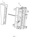
- FIG. 1 shows joint assembly in a substantially assembled form and a luminaire L.
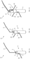
- FIGs. 1A to 1C best show a pin 10 of joint assembly 100 (pin 10 is obscured from view in FIG. 1 ).
- Pin 10 includes a base section 12 and two secondary sections 18 sequentially stacked on top of base section 12.
- the shape of the tops of base section 12 and secondary sections 18 may be frustoconical, and the bottoms of secondary sections 18 may be a corresponding concave shape to facilitate engagement between the pin sections.
- the sections may be detachably connected.
- the sections may be fixedly connected once initially connected.
- Base section 12 and secondary sections 18 are rotatably coupled such that each section can rotate independently of another. In some embodiments the sections may not be rotatable with respect to each other.
- Base section 12 has an upper opening 14, a bore 16 connected to upper opening 14, and a side opening 18 connected to bore 16.
- Each secondary section 22, 22' has an upper opening 24, 24' a bore 26, 26' connected to upper opening 24, 24', and a side opening 28, 28' connected to bore 26, 26'.
- Side opening 28, 28' may be a slot continuous with bore 26, 26' as best shown in FIG. 1C .
- Bore 16 of base section 12 axially aligns with bores 26, 26' of secondary sections 22, 22'.
- power cable 20A is split from primary power cable 20 and is fed into top opening 14, through bore 16, and out side opening 18 for connection to a luminaire L corresponding to base section 12.
- Side opening 18 may have an outwardly and downwardly tapering lower surface 19 to facilitate feeding and extending of power cable 20A therethrough.
- a power cable 20B is split from primary power cable 20 and extends through upper opening 24, bore 26 and out side opening 28 for connection to a luminaire L corresponding to secondary section 22.
- a power cable 20C split from primary power cable 20 extends through upper opening 24', bore 26' and out side opening 28' for connection to a luminaire L corresponding to secondary section 22'.
- base section 12 and secondary sections 22 of pin 10 may be assembled first, and then respective power cables 20A, 20B, 20C fed through their respective side openings 18, 28, 28'.
- side openings 28, 28' may be slots that extend up to a height of secondary sections 22, 22' to facilitate the splitting off and feeding through of power cables 20B, 20C.
- upper openings 14, 24, 24' and bores 16, 26, 26' of base section 12 and secondary sections 22 are vertically aligned when assembled to form pin 10.
- the height of secondary sections 22,22' may be less than the height of base section 12.
- the circumference of secondary sections 22,22' and base section 12' may be substantially the same.
- FIGs. 2A and 2B show pin 10 and a primary hinge 30 of joint assembly 100, and in particular the coupling of these two components.
- Primary hinge 30 includes a vertical base 32 from which a plurality of vertically spaced apart primary knuckles 34 extend.
- Primary knuckles 34 are spaced apart by gaps 36. In some embodiments the thickness of primary knuckles 34 and the height of gaps 36 may be substantially similar.
- Distal portions of primary knuckles 32 are configured to engage pin 10. As shown in FIGs. 2A and 2B , distal portions of primary knuckles 32 comprise vertically aligned holes 38 through which pin 10 extends. The shape of holes 38 corresponds to the horizontal cross-section of pin 10. Here, pin 10 is cylindrical and holes 36 are circular.
- Primary knuckles 34 and gaps 36 are spaced such that side openings 18, 28 of pin 10 correspond to the location of gaps 36 to allow unimpeded extension of power cables 20A, 20B, 20C out of primary hinge 30 into secondary hinges 46, 46', 46" for connecting to their respective luminaires L as described herein.
- FIGs. 2B and 3 also show that an upper portion of primary hinge 30 includes two horizontal power cable channels 42 connected to a vertical power cable channel 44 for receiving, feeding and/or separating primary power cable 20.
- Horizontal power cable channels 42 and vertical power cable channel 44 may be part of a cord suspension slider 45 that slidably engageable in slot 43 defined in an upper portion of primary hinge 30.
- vertical power cable channel 44 may be axially aligned with upper openings 14, 24 and bores 16, 26 of base section 12 and secondary sections 22 of pin 10.
- vertical power cable channel 44 may receive a primary power cable 20 from the ceiling to supply power to the luminaires (and to suspend) luminaires L through joint assembly 100; in this case primary power cable 20 may then split off as power cable 20D through one of horizontal power cable channels 42 to provide power to a luminaire L connected to primary hinge 30; the remainder of primary power cable 20 may be distributed as power cables 20A, 20B, and 20C as described above.
- primary power cables 20 may split off into power cable 20E for powering other luminaires L' of an adjacent joint assembly, by feeding power cable 20E through the other horizontal power cable channel 42, through luminaire L corresponding to primary hinge 30, and then to one or more other luminaires L', or another joint assembly, connected to luminaire L.
- power to luminaires L of joint assembly 100 may not be supplied directly from the ceiling and vertical power cable channel 44, but rather through an adjacent joint assembly, or a luminaire L' of an adjacent joint assembly, fed directly to, or through luminaire L' connected to, luminaire L corresponding to primary hinge 30, and then through one of horizontal power cable channels 42 as alternate primary power cable 20E (in which case vertical power cable channel 44 may be used for a suspension cable only).
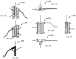
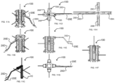
- FIGs. 11A to 11 E, 11G and 11H Both of the foregoing embodiments are shown in FIGs. 11A to 11 E, 11G and 11H .
- FIG. 11I shows yet another possibility where the luminaires of joint assembly 100 are fed by different power sources.
- Primary power cable 20 from the ceiling splits into power cables 20B and 20D for power two opposing luminaires.
- Primary power cable 20 also splits into power cable 20E for powering luminaires connected to another joint assembly adjacent to the luminaire powered by power cable 20D.
- Power cables 20A and 20C are powered by a different power source, either from another joint assembly adjacent to the luminaire powered by power cable 20A or adjacent to the luminaire powered by power cable 20C.
- FIGs. 4 to 6 show secondary hinges 46, 46', 46" of joint assembly 100.
- Secondary hinges 46, 46', 46" include a secondary vertical base 48, 48' and at least two secondary knuckles 50, 50', 50" extending generally perpendicularly from secondary vertical base 48, 48', 48".
- Secondary knuckles 50, 50', 50" are similar in features and functions to primary knuckles 34.
- Secondary knuckles 50, 50', 50" are spaced apart along secondary vertical base 48, 48', 48” such that each secondary knuckle 50, 50', 50” is positioned between primary knuckles 34 when coupled to pin 10, as shown for example in FIG. 7 .
- secondary knuckles 50, 50', 50" may be positioned between primary knuckles 34 and/or secondary knuckles 50, 50' of a different secondary hinge 46, 46'.
- FIGs. 1 and 7 shows joint assembly 100 with primary hinge 30 and all three secondary hinges 46, 46', 46" coupled to pin 10 (obscured from view in FIGs. 5 and 7 ).
- Primary hinge 30 and secondary hinges 46, 46', 46" may engage pin 10 such that primary knuckles 34 and secondary knuckles 50, 50', 50" are interleaved.
- Each of secondary knuckles 50, 50', 50" is positioned between two primary knuckles 34 and within gaps 36 of primary hinge 30.
- secondary hinges 46, 46', 46" include through-holes 52, 52', 52" disposed in secondary vertical base 48, 48', 48" for respective power cables 20A, 20B, 20C to pass through.
- Through-holes 52, 52', 52" are generally horizontally aligned with corresponding side openings 18, 28 of pin 10 where power cables 20A, 20B, 20C exit out of pin 10 to connect to corresponding luminaires L.
- through-holes 52, 52', 52" extend at least partially through corresponding secondary knuckles 50, 50', 50" and open at hole 38 of corresponding secondary knuckles 50, 50', 50" for receiving power cables 20A, 20B, 20C.
- an attachment mechanism such as a luminaire attachment bracket 54 as shown in FIG. 6 may be used.
- the distal face of primary hinge 30 or secondary hinge 46, 46', 46" may be adapted to engage bracket 54 for coupling a luminaire L to hinge, as shown in FIG. 1 .
- Bracket 54 may have a through-hole 56 for power cable 20A, 20B, 20C to pass through and power corresponding luminaire L.
- through-hole 56 is aligned with through-hole 52, 52', 52" for power cable 20A, 20B, 20C to pass from pin 10 to corresponding luminaire L.
- primary hinge 30 and secondary hinges 46, 46', 46" may be rotated rotate about pin 10 to adjust the orientation of luminaires L coupled to joint assembly 100. Such adjustments may be made before, during and/or after installation.
- joint assembly 100 connects four luminaires L in a cross-shaped arrangement.
- Side opening 18 of base section 12 and side openings 28 of the two secondary sections 22 may each initially be configured at 90, 180 and 270 degrees from the direction of horizontal power cable channel 42 of primary hinge 30 by suitably rotating base section 12 and secondary sections 22 in relation to primary hinge 30.
- base section 12 and/or secondary sections 22 may inadvertently rotate, resulting in a misalignment from their desired positions.
- the hinges or the luminaires L themselves may be manually rotated into the desired position, and any significant misalignment of base section 12 and/or secondary sections 22 will be corrected by abutment of the power cable against side openings 18, 28 and the distal opening of through-holes 52, 52', 52" as the hinges or luminaires are rotated (see FIGs. 4 to 6 ).
- FIGS. 8A-8H shows a joint assembly 200 according to another embodiment.
- Joint assembly 200 has functions and features similar to joint assembly 100 except it has one secondary hinge instead of three secondary hinges.
- Joint assembly 200 includes a pin 210, primary hinge 230 and one secondary hinge 246 to support two luminaires L.
- One luminaire L is coupled to primary hinge 230, and another luminaire L is coupled to secondary hinge 246.
- primary and secondary hinges 230, 246 are shown oriented and aligned in the same vertical plane. The luminaires are therefore also aligned in the same vertical plane, positioned on either side of pin 210, as shown in FIG. 8H .
- primary hinge 230 and/or secondary hinge 246 may be rotatable, allowing the luminaires to be at any desirable angle with respect to each other.
- FIGs. 9A to 9G show joint assembly 200 with the hinges, and therefore the luminaires, configured in a perpendicular position to each other.
- a primary power cable 220 may be supplied from the ceiling and split off into power cable 220B which connects to luminaire L connected to primary hinge 230 by passing through vertical power cable channel 244 and one of the horizontal power cable channels 242 located at an upper portion of primary hinge 230.
- Primary power cable 220 may also be fed through the other horizontal power cable channel 242 to connect to an adjacent luminaire L' (not shown) through luminaire L.
- Primary power cable 220 also splits off into power cable 220A to power luminaire L coupled to secondary hinge 246.
- Power cable 220B passes through pin 210 (i.e. through a top opening, bore, and out a side opening) to connect to luminaire L.
- FIGs. 10A to 10G show a joint assembly 300 according to another embodiment.
- Joint assembly 300 is similar in function and features to joint assemblies 100 and 200 except joint assembly 300 has three hinges, i.e., a primary hinge and two secondary hinges, to connect three luminaires L.
- the three hinges may for example be oriented to form a generally T-shape.
- the three hinges may be further adjusted by rotating/pivoting around the pin to form other patterns/orientations with three luminaires (e.g. a Y-shape, etc.).
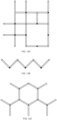
- FIGs. 12A to 12C show example embodiments of arrangements of luminaires using joint assemblies of the present invention.
- the filled in squares and triangles represent joint assemblies where a power cable from the ceiling is used for suspension, and the empty squares and triangles represent joint assemblies with only a suspension cable from the ceiling (i.e., no power cable).
Landscapes
- Engineering & Computer Science (AREA)
- General Engineering & Computer Science (AREA)
- Pivots And Pivotal Connections (AREA)
- Non-Portable Lighting Devices Or Systems Thereof (AREA)
- Mechanical Engineering (AREA)
Claims (15)
- Gelenkanordnung für Leuchten (L), mit:
einem Stift (10) mit mindestens einem Stiftabschnitt (12, 22, 22'), wobei jeder Stiftabschnitt Folgendes aufweist:eine obere Öffnung (14, 24, 24');eine seitliche Öffnung (18, 28, 28');eine Bohrung (16, 26, 26'), die die obere Öffnung und die seitliche Öffnung verbindet;wobei die obere Öffnung dazu ausgestaltet ist, mindestens ein Stromkabel (20) aufzunehmen, um es durch die Bohrung und aus der seitlichen Öffnung herauszuführen;ein primäres Scharnier (30) mit:einem primären vertikalen Sockel (32) zur Befestigung an einer Leuchte oder Wand;einer Mehrzahl von primären Achsschenkeln (34), die sich von der vertikalen Basis aus erstrecken, wobei ein distaler Teil der Achsschenkel Stifteingriffsmittel (38) aufweist; undmindestens ein sekundäres Scharnier (46, 46', 46") mit:einem sekundären vertikalen Sockel (48, 48', 48") zum Anschluss an eine zusätzliche Leuchte;einer Mehrzahl von sekundären Achsschenkeln (50, 50', 50"), die sich von der vertikalen Basis aus erstrecken, wobei ein distaler Teil der Achsschenkel Stifteingriffsmittel zum Eingreifen des Stifts aufweist. - Gelenkanordnung nach Anspruch 1, wobei das primäre Scharnier, das mindestens eine sekundäre Scharnier oder beide drehbar mit dem Stift verbunden sind.
- Gelenkanordnung nach Anspruch 1 oder 2, wobei die primären Achsschenkel und sekundären Achsschenkel ineinandergreifen.
- Gelenkbaugruppe nach Anspruch 1, wobei die seitlichen Öffnungen des Stiftabschnitts horizontal mit den Lücken zwischen den mehreren primären Achsschenkeln ausgerichtet sind.
- Gelenkanordnung nach einem Ansprüche 1 bis 4, wobei das mindestens eine sekundäre Scharnier ein Durchgangsloch aufweist, das sich durch den sekundären vertikalen Sockel zur Aufnahme des mindestens einen Stromkabels von einer entsprechenden Seitenöffnung des Stifts zur Zuführung zu einer Leuchte erstreckt, die mit dem mindestens einen sekundären Scharnier verbindbar ist.
- Gelenkanordnung nach Anspruch 5, wobei das Durchgangsloch und die entsprechende Seitenöffnung horizontal ausgerichtet sind.
- Gelenkanordnung nach Anspruch 6, wobei sich das Durchgangsloch zumindest teilweise durch mindestens einen der Mehrzahl von sekundären Achsschenkeln erstreckt.
- Gelenkanordnung nach Anspruch 7, wobei sich das Durchgangsloch bei dem Loch von mindestens einem der mehreren Sekundär-Achsschenkel öffnet.
- Gelenkanordnung nach einem der Ansprüche 1 bis 8, wobei ein oberer Teil des primären Gelenks mindestens einen vertikalen Stromkabelkanal und mindestens einen horizontalen Stromkabelkanal aufweist.
- Gelenkanordnung nach Anspruch 9, wobei der obere Teil zwei horizontale Stromkabelkanäle umfasst.
- Gelenkanordnung nach einem Ansprüche 1 bis 10, wobei die Seitenöffnung eine sich nach außen und unten verjüngende untere Fläche aufweist.
- Gelenkanordnung nach einem der Ansprüche 1 bis 11, wobei der Stift Folgendes aufweist: zwei oder mehr Stiftabschnitte, wobei die Stiftabschnitte gestapelt sind, um den Stift zu bilden, und wobei die Stiftabschnitte zylindrisch und in Bezug zueinander drehbar sind.
- Gelenkanordnung nach einem der Ansprüche 1 bis 12, wobei jedes der primären Scharniere und der mindestens einen sekundären Scharniere eine Halterung zur Verbindung der primären und sekundären vertikalen Sockel mit den entsprechenden Leuchten aufweist.
- Gelenkbaugruppe nach einem der Ansprüche 1 bis 13, wobei das Stifteingriffsmittel ein Loch im distalen Teil der Achsschenkel aufweist.
- Gelenkanordnung nach einem Ansprüche 1 bis 14 mit einem, zwei oder drei sekundären Scharnieren.
Applications Claiming Priority (1)
| Application Number | Priority Date | Filing Date | Title |
|---|---|---|---|
| US202263324832P | 2022-03-29 | 2022-03-29 |
Publications (3)
| Publication Number | Publication Date |
|---|---|
| EP4253825A1 EP4253825A1 (de) | 2023-10-04 |
| EP4253825B1 true EP4253825B1 (de) | 2025-05-07 |
| EP4253825C0 EP4253825C0 (de) | 2025-05-07 |
Family
ID=85772120
Family Applications (1)
| Application Number | Title | Priority Date | Filing Date |
|---|---|---|---|
| EP23163203.5A Active EP4253825B1 (de) | 2022-03-29 | 2023-03-21 | Verbindungsanordnung für leuchten |
Country Status (3)
| Country | Link |
|---|---|
| US (1) | US11841131B2 (de) |
| EP (1) | EP4253825B1 (de) |
| CA (1) | CA3193058A1 (de) |
Families Citing this family (3)
| Publication number | Priority date | Publication date | Assignee | Title |
|---|---|---|---|---|
| USD1060808S1 (en) * | 2022-04-08 | 2025-02-04 | Lmpg Inc. | Luminaire joint |
| US20250067409A1 (en) * | 2023-08-21 | 2025-02-27 | Kuzco Lighting Llc | Modular lighting |
| DE202024105085U1 (de) * | 2024-09-05 | 2024-09-19 | Arnold & Richter Cine Technik Gmbh & Co. Betriebs Kg | Befestigungseinrichtung für eine Beleuchtungseinheit und Beleuchtungseinheit |
Family Cites Families (7)
| Publication number | Priority date | Publication date | Assignee | Title |
|---|---|---|---|---|
| US3842386A (en) * | 1972-07-20 | 1974-10-15 | Stanley Works | Hinge for passing electrical current |
| US4412711A (en) * | 1981-12-03 | 1983-11-01 | The Stanley Works | Two knuckle electrical hinge |
| US5586895A (en) * | 1995-10-23 | 1996-12-24 | Zehrung; Raymond E. | Power transfer hinge |
| CN101469841B (zh) | 2007-12-28 | 2011-03-30 | 富士迈半导体精密工业(上海)有限公司 | 照明装置 |
| KR100988830B1 (ko) | 2010-07-26 | 2010-10-20 | (주)이텍 | 등주용 엘이디 등기구 |
| DE202011052457U1 (de) * | 2011-12-23 | 2013-03-25 | Dr. Hahn Gmbh & Co. Kg | Vorrichtung zur Übertragung von elektrischer Energie und/oder elektrischen Signalen von einer feststehenden Wand auf einen an der Wand befestigten Flügel |
| US11125424B2 (en) * | 2019-03-08 | 2021-09-21 | Abl Ip Holding Llc | Luminaire mounting assembly |
-
2023
- 2023-03-15 US US18/121,888 patent/US11841131B2/en active Active
- 2023-03-15 CA CA3193058A patent/CA3193058A1/en active Pending
- 2023-03-21 EP EP23163203.5A patent/EP4253825B1/de active Active
Also Published As
| Publication number | Publication date |
|---|---|
| US20230313979A1 (en) | 2023-10-05 |
| EP4253825A1 (de) | 2023-10-04 |
| CA3193058A1 (en) | 2023-09-29 |
| US11841131B2 (en) | 2023-12-12 |
| EP4253825C0 (de) | 2025-05-07 |
Similar Documents
| Publication | Publication Date | Title |
|---|---|---|
| EP4253825A1 (de) | Verbindungsanordnung für leuchten | |
| US6843581B2 (en) | Luminaire pendant system | |
| JPH0315215A (ja) | モジューラ式家具 | |
| US10034539B2 (en) | Connector hub and modular work system | |
| CA2175553C (en) | Integral joint and mounting assembly for suspended linear structures | |
| US5412552A (en) | Lighting lamp bar | |
| US5544593A (en) | Adjustable desk system | |
| CA2321343C (en) | Linear fixture suspension system | |
| EP0787378B1 (de) | Kabelträger | |
| US8469323B1 (en) | Modular monitor support assembly | |
| US20030060067A1 (en) | Quick connect device for electrical fixture | |
| WO1994014253A1 (en) | Telecommunication overhead cable distribution assembly | |
| CA2292449A1 (en) | Worktop and frame construction | |
| CA2686758A1 (en) | A linear lighting system having a spinal structure and an optical system separately installable thereon | |
| KR102389977B1 (ko) | 분전반용 전원 분배장치 | |
| US20050286256A1 (en) | Small profile hanger system for ceiling suspended lighting fixtures | |
| US11608969B2 (en) | Luminaire structures | |
| AU764114B2 (en) | Arm apparatus for mounting electronic devices | |
| WO2018141000A1 (en) | Modular support system and method of supporting one or more components | |
| KR102682254B1 (ko) | 천정 고정형 전기 케이블 트레이 | |
| US6318698B1 (en) | Suspension device for an object | |
| CN216766740U (zh) | 一种爬架支撑结构用紧固装置 | |
| US5339585A (en) | Raceway swivel spacer leg assembly | |
| JP3304070B2 (ja) | 配線装置 | |
| DE4002076C2 (de) |
Legal Events
| Date | Code | Title | Description |
|---|---|---|---|
| PUAI | Public reference made under article 153(3) epc to a published international application that has entered the european phase |
Free format text: ORIGINAL CODE: 0009012 |
|
| STAA | Information on the status of an ep patent application or granted ep patent |
Free format text: STATUS: THE APPLICATION HAS BEEN PUBLISHED |
|
| AK | Designated contracting states |
Kind code of ref document: A1 Designated state(s): AL AT BE BG CH CY CZ DE DK EE ES FI FR GB GR HR HU IE IS IT LI LT LU LV MC ME MK MT NL NO PL PT RO RS SE SI SK SM TR |
|
| STAA | Information on the status of an ep patent application or granted ep patent |
Free format text: STATUS: REQUEST FOR EXAMINATION WAS MADE |
|
| 17P | Request for examination filed |
Effective date: 20240404 |
|
| RBV | Designated contracting states (corrected) |
Designated state(s): AL AT BE BG CH CY CZ DE DK EE ES FI FR GB GR HR HU IE IS IT LI LT LU LV MC ME MK MT NL NO PL PT RO RS SE SI SK SM TR |
|
| GRAP | Despatch of communication of intention to grant a patent |
Free format text: ORIGINAL CODE: EPIDOSNIGR1 |
|
| STAA | Information on the status of an ep patent application or granted ep patent |
Free format text: STATUS: GRANT OF PATENT IS INTENDED |
|
| INTG | Intention to grant announced |
Effective date: 20241120 |
|
| GRAS | Grant fee paid |
Free format text: ORIGINAL CODE: EPIDOSNIGR3 |
|
| GRAA | (expected) grant |
Free format text: ORIGINAL CODE: 0009210 |
|
| STAA | Information on the status of an ep patent application or granted ep patent |
Free format text: STATUS: THE PATENT HAS BEEN GRANTED |
|
| AK | Designated contracting states |
Kind code of ref document: B1 Designated state(s): AL AT BE BG CH CY CZ DE DK EE ES FI FR GB GR HR HU IE IS IT LI LT LU LV MC ME MK MT NL NO PL PT RO RS SE SI SK SM TR |
|
| REG | Reference to a national code |
Ref country code: GB Ref legal event code: FG4D |
|
| REG | Reference to a national code |
Ref country code: CH Ref legal event code: EP |
|
| REG | Reference to a national code |
Ref country code: IE Ref legal event code: FG4D |
|
| U01 | Request for unitary effect filed |
Effective date: 20250507 |
|
| U07 | Unitary effect registered |
Designated state(s): AT BE BG DE DK EE FI FR IT LT LU LV MT NL PT RO SE SI Effective date: 20250513 |
|
| PG25 | Lapsed in a contracting state [announced via postgrant information from national office to epo] |
Ref country code: ES Free format text: LAPSE BECAUSE OF FAILURE TO SUBMIT A TRANSLATION OF THE DESCRIPTION OR TO PAY THE FEE WITHIN THE PRESCRIBED TIME-LIMIT Effective date: 20250507 |
|
| PG25 | Lapsed in a contracting state [announced via postgrant information from national office to epo] |
Ref country code: GR Free format text: LAPSE BECAUSE OF FAILURE TO SUBMIT A TRANSLATION OF THE DESCRIPTION OR TO PAY THE FEE WITHIN THE PRESCRIBED TIME-LIMIT Effective date: 20250808 Ref country code: NO Free format text: LAPSE BECAUSE OF FAILURE TO SUBMIT A TRANSLATION OF THE DESCRIPTION OR TO PAY THE FEE WITHIN THE PRESCRIBED TIME-LIMIT Effective date: 20250807 |
|
| PG25 | Lapsed in a contracting state [announced via postgrant information from national office to epo] |
Ref country code: PL Free format text: LAPSE BECAUSE OF FAILURE TO SUBMIT A TRANSLATION OF THE DESCRIPTION OR TO PAY THE FEE WITHIN THE PRESCRIBED TIME-LIMIT Effective date: 20250507 |
|
| PG25 | Lapsed in a contracting state [announced via postgrant information from national office to epo] |
Ref country code: HR Free format text: LAPSE BECAUSE OF FAILURE TO SUBMIT A TRANSLATION OF THE DESCRIPTION OR TO PAY THE FEE WITHIN THE PRESCRIBED TIME-LIMIT Effective date: 20250507 |
|
| PG25 | Lapsed in a contracting state [announced via postgrant information from national office to epo] |
Ref country code: RS Free format text: LAPSE BECAUSE OF FAILURE TO SUBMIT A TRANSLATION OF THE DESCRIPTION OR TO PAY THE FEE WITHIN THE PRESCRIBED TIME-LIMIT Effective date: 20250807 |
|
| PG25 | Lapsed in a contracting state [announced via postgrant information from national office to epo] |
Ref country code: IS Free format text: LAPSE BECAUSE OF FAILURE TO SUBMIT A TRANSLATION OF THE DESCRIPTION OR TO PAY THE FEE WITHIN THE PRESCRIBED TIME-LIMIT Effective date: 20250907 |
|
| PG25 | Lapsed in a contracting state [announced via postgrant information from national office to epo] |
Ref country code: SM Free format text: LAPSE BECAUSE OF FAILURE TO SUBMIT A TRANSLATION OF THE DESCRIPTION OR TO PAY THE FEE WITHIN THE PRESCRIBED TIME-LIMIT Effective date: 20250507 |
|
| PG25 | Lapsed in a contracting state [announced via postgrant information from national office to epo] |
Ref country code: CZ Free format text: LAPSE BECAUSE OF FAILURE TO SUBMIT A TRANSLATION OF THE DESCRIPTION OR TO PAY THE FEE WITHIN THE PRESCRIBED TIME-LIMIT Effective date: 20250507 |
|
| PG25 | Lapsed in a contracting state [announced via postgrant information from national office to epo] |
Ref country code: SK Free format text: LAPSE BECAUSE OF FAILURE TO SUBMIT A TRANSLATION OF THE DESCRIPTION OR TO PAY THE FEE WITHIN THE PRESCRIBED TIME-LIMIT Effective date: 20250507 |
|
| PLBE | No opposition filed within time limit |
Free format text: ORIGINAL CODE: 0009261 |
|
| STAA | Information on the status of an ep patent application or granted ep patent |
Free format text: STATUS: NO OPPOSITION FILED WITHIN TIME LIMIT |
|
| REG | Reference to a national code |
Ref country code: CH Ref legal event code: L10 Free format text: ST27 STATUS EVENT CODE: U-0-0-L10-L00 (AS PROVIDED BY THE NATIONAL OFFICE) Effective date: 20260318 |
|
| 26N | No opposition filed |
Effective date: 20260210 |
|
| U20 | Renewal fee for the european patent with unitary effect paid |
Year of fee payment: 4 Effective date: 20260327 |