EP4253129A1 - Système de refroidissement de véhicule électrique - Google Patents
Système de refroidissement de véhicule électrique Download PDFInfo
- Publication number
- EP4253129A1 EP4253129A1 EP23164236.4A EP23164236A EP4253129A1 EP 4253129 A1 EP4253129 A1 EP 4253129A1 EP 23164236 A EP23164236 A EP 23164236A EP 4253129 A1 EP4253129 A1 EP 4253129A1
- Authority
- EP
- European Patent Office
- Prior art keywords
- charger
- coolant
- drive unit
- temperature
- vehicle
- Prior art date
- Legal status (The legal status is an assumption and is not a legal conclusion. Google has not performed a legal analysis and makes no representation as to the accuracy of the status listed.)
- Pending
Links
- 238000001816 cooling Methods 0.000 title claims abstract description 115
- 239000002826 coolant Substances 0.000 claims abstract description 170
- 238000011144 upstream manufacturing Methods 0.000 claims description 11
- 238000000034 method Methods 0.000 claims description 10
- 230000009467 reduction Effects 0.000 description 7
- 230000006872 improvement Effects 0.000 description 6
- 239000004606 Fillers/Extenders Substances 0.000 description 4
- 230000007423 decrease Effects 0.000 description 4
- XLYOFNOQVPJJNP-UHFFFAOYSA-N water Substances O XLYOFNOQVPJJNP-UHFFFAOYSA-N 0.000 description 4
- LYCAIKOWRPUZTN-UHFFFAOYSA-N Ethylene glycol Chemical compound OCCO LYCAIKOWRPUZTN-UHFFFAOYSA-N 0.000 description 3
- 239000003990 capacitor Substances 0.000 description 3
- 238000010586 diagram Methods 0.000 description 3
- 230000002159 abnormal effect Effects 0.000 description 2
- 230000002528 anti-freeze Effects 0.000 description 2
- 230000003247 decreasing effect Effects 0.000 description 2
- 238000009434 installation Methods 0.000 description 2
- 241000208479 Anagallis arvensis Species 0.000 description 1
- 230000005856 abnormality Effects 0.000 description 1
- 230000001174 ascending effect Effects 0.000 description 1
- 230000005540 biological transmission Effects 0.000 description 1
- 230000008859 change Effects 0.000 description 1
- 238000006243 chemical reaction Methods 0.000 description 1
- 238000006073 displacement reaction Methods 0.000 description 1
- 230000000694 effects Effects 0.000 description 1
- 230000005611 electricity Effects 0.000 description 1
- 238000005516 engineering process Methods 0.000 description 1
- 238000002474 experimental method Methods 0.000 description 1
- 238000005259 measurement Methods 0.000 description 1
- 238000010248 power generation Methods 0.000 description 1
- 230000008929 regeneration Effects 0.000 description 1
- 238000011069 regeneration method Methods 0.000 description 1
- 230000001360 synchronised effect Effects 0.000 description 1
Images


Classifications
-
- B—PERFORMING OPERATIONS; TRANSPORTING
- B60—VEHICLES IN GENERAL
- B60K—ARRANGEMENT OR MOUNTING OF PROPULSION UNITS OR OF TRANSMISSIONS IN VEHICLES; ARRANGEMENT OR MOUNTING OF PLURAL DIVERSE PRIME-MOVERS IN VEHICLES; AUXILIARY DRIVES FOR VEHICLES; INSTRUMENTATION OR DASHBOARDS FOR VEHICLES; ARRANGEMENTS IN CONNECTION WITH COOLING, AIR INTAKE, GAS EXHAUST OR FUEL SUPPLY OF PROPULSION UNITS IN VEHICLES
- B60K11/00—Arrangement in connection with cooling of propulsion units
- B60K11/02—Arrangement in connection with cooling of propulsion units with liquid cooling
- B60K11/04—Arrangement or mounting of radiators, radiator shutters, or radiator blinds
-
- B—PERFORMING OPERATIONS; TRANSPORTING
- B60—VEHICLES IN GENERAL
- B60L—PROPULSION OF ELECTRICALLY-PROPELLED VEHICLES; SUPPLYING ELECTRIC POWER FOR AUXILIARY EQUIPMENT OF ELECTRICALLY-PROPELLED VEHICLES; ELECTRODYNAMIC BRAKE SYSTEMS FOR VEHICLES IN GENERAL; MAGNETIC SUSPENSION OR LEVITATION FOR VEHICLES; MONITORING OPERATING VARIABLES OF ELECTRICALLY-PROPELLED VEHICLES; ELECTRIC SAFETY DEVICES FOR ELECTRICALLY-PROPELLED VEHICLES
- B60L53/00—Methods of charging batteries, specially adapted for electric vehicles; Charging stations or on-board charging equipment therefor; Exchange of energy storage elements in electric vehicles
- B60L53/30—Constructional details of charging stations
- B60L53/302—Cooling of charging equipment
-
- B—PERFORMING OPERATIONS; TRANSPORTING
- B60—VEHICLES IN GENERAL
- B60K—ARRANGEMENT OR MOUNTING OF PROPULSION UNITS OR OF TRANSMISSIONS IN VEHICLES; ARRANGEMENT OR MOUNTING OF PLURAL DIVERSE PRIME-MOVERS IN VEHICLES; AUXILIARY DRIVES FOR VEHICLES; INSTRUMENTATION OR DASHBOARDS FOR VEHICLES; ARRANGEMENTS IN CONNECTION WITH COOLING, AIR INTAKE, GAS EXHAUST OR FUEL SUPPLY OF PROPULSION UNITS IN VEHICLES
- B60K1/00—Arrangement or mounting of electrical propulsion units
-
- B—PERFORMING OPERATIONS; TRANSPORTING
- B60—VEHICLES IN GENERAL
- B60K—ARRANGEMENT OR MOUNTING OF PROPULSION UNITS OR OF TRANSMISSIONS IN VEHICLES; ARRANGEMENT OR MOUNTING OF PLURAL DIVERSE PRIME-MOVERS IN VEHICLES; AUXILIARY DRIVES FOR VEHICLES; INSTRUMENTATION OR DASHBOARDS FOR VEHICLES; ARRANGEMENTS IN CONNECTION WITH COOLING, AIR INTAKE, GAS EXHAUST OR FUEL SUPPLY OF PROPULSION UNITS IN VEHICLES
- B60K11/00—Arrangement in connection with cooling of propulsion units
- B60K11/02—Arrangement in connection with cooling of propulsion units with liquid cooling
-
- B—PERFORMING OPERATIONS; TRANSPORTING
- B60—VEHICLES IN GENERAL
- B60L—PROPULSION OF ELECTRICALLY-PROPELLED VEHICLES; SUPPLYING ELECTRIC POWER FOR AUXILIARY EQUIPMENT OF ELECTRICALLY-PROPELLED VEHICLES; ELECTRODYNAMIC BRAKE SYSTEMS FOR VEHICLES IN GENERAL; MAGNETIC SUSPENSION OR LEVITATION FOR VEHICLES; MONITORING OPERATING VARIABLES OF ELECTRICALLY-PROPELLED VEHICLES; ELECTRIC SAFETY DEVICES FOR ELECTRICALLY-PROPELLED VEHICLES
- B60L53/00—Methods of charging batteries, specially adapted for electric vehicles; Charging stations or on-board charging equipment therefor; Exchange of energy storage elements in electric vehicles
- B60L53/20—Methods of charging batteries, specially adapted for electric vehicles; Charging stations or on-board charging equipment therefor; Exchange of energy storage elements in electric vehicles characterised by converters located in the vehicle
- B60L53/22—Constructional details or arrangements of charging converters specially adapted for charging electric vehicles
-
- H—ELECTRICITY
- H02—GENERATION; CONVERSION OR DISTRIBUTION OF ELECTRIC POWER
- H02K—DYNAMO-ELECTRIC MACHINES
- H02K11/00—Structural association of dynamo-electric machines with electric components or with devices for shielding, monitoring or protection
- H02K11/20—Structural association of dynamo-electric machines with electric components or with devices for shielding, monitoring or protection for measuring, monitoring, testing, protecting or switching
- H02K11/25—Devices for sensing temperature, or actuated thereby
-
- H—ELECTRICITY
- H02—GENERATION; CONVERSION OR DISTRIBUTION OF ELECTRIC POWER
- H02K—DYNAMO-ELECTRIC MACHINES
- H02K11/00—Structural association of dynamo-electric machines with electric components or with devices for shielding, monitoring or protection
- H02K11/30—Structural association with control circuits or drive circuits
- H02K11/33—Drive circuits, e.g. power electronics
-
- H—ELECTRICITY
- H02—GENERATION; CONVERSION OR DISTRIBUTION OF ELECTRIC POWER
- H02K—DYNAMO-ELECTRIC MACHINES
- H02K9/00—Arrangements for cooling or ventilating
- H02K9/19—Arrangements for cooling or ventilating for machines with closed casing and closed-circuit cooling using a liquid cooling medium, e.g. oil
- H02K9/193—Arrangements for cooling or ventilating for machines with closed casing and closed-circuit cooling using a liquid cooling medium, e.g. oil with provision for replenishing the cooling medium; with means for preventing leakage of the cooling medium
-
- H—ELECTRICITY
- H05—ELECTRIC TECHNIQUES NOT OTHERWISE PROVIDED FOR
- H05K—PRINTED CIRCUITS; CASINGS OR CONSTRUCTIONAL DETAILS OF ELECTRIC APPARATUS; MANUFACTURE OF ASSEMBLAGES OF ELECTRICAL COMPONENTS
- H05K7/00—Constructional details common to different types of electric apparatus
- H05K7/20—Modifications to facilitate cooling, ventilating, or heating
- H05K7/2089—Modifications to facilitate cooling, ventilating, or heating for power electronics, e.g. for inverters for controlling motor
- H05K7/209—Heat transfer by conduction from internal heat source to heat radiating structure
-
- H—ELECTRICITY
- H05—ELECTRIC TECHNIQUES NOT OTHERWISE PROVIDED FOR
- H05K—PRINTED CIRCUITS; CASINGS OR CONSTRUCTIONAL DETAILS OF ELECTRIC APPARATUS; MANUFACTURE OF ASSEMBLAGES OF ELECTRICAL COMPONENTS
- H05K7/00—Constructional details common to different types of electric apparatus
- H05K7/20—Modifications to facilitate cooling, ventilating, or heating
- H05K7/2089—Modifications to facilitate cooling, ventilating, or heating for power electronics, e.g. for inverters for controlling motor
- H05K7/20927—Liquid coolant without phase change
-
- B—PERFORMING OPERATIONS; TRANSPORTING
- B60—VEHICLES IN GENERAL
- B60K—ARRANGEMENT OR MOUNTING OF PROPULSION UNITS OR OF TRANSMISSIONS IN VEHICLES; ARRANGEMENT OR MOUNTING OF PLURAL DIVERSE PRIME-MOVERS IN VEHICLES; AUXILIARY DRIVES FOR VEHICLES; INSTRUMENTATION OR DASHBOARDS FOR VEHICLES; ARRANGEMENTS IN CONNECTION WITH COOLING, AIR INTAKE, GAS EXHAUST OR FUEL SUPPLY OF PROPULSION UNITS IN VEHICLES
- B60K1/00—Arrangement or mounting of electrical propulsion units
- B60K2001/003—Arrangement or mounting of electrical propulsion units with means for cooling the electrical propulsion units
- B60K2001/006—Arrangement or mounting of electrical propulsion units with means for cooling the electrical propulsion units the electric motors
-
- B—PERFORMING OPERATIONS; TRANSPORTING
- B60—VEHICLES IN GENERAL
- B60L—PROPULSION OF ELECTRICALLY-PROPELLED VEHICLES; SUPPLYING ELECTRIC POWER FOR AUXILIARY EQUIPMENT OF ELECTRICALLY-PROPELLED VEHICLES; ELECTRODYNAMIC BRAKE SYSTEMS FOR VEHICLES IN GENERAL; MAGNETIC SUSPENSION OR LEVITATION FOR VEHICLES; MONITORING OPERATING VARIABLES OF ELECTRICALLY-PROPELLED VEHICLES; ELECTRIC SAFETY DEVICES FOR ELECTRICALLY-PROPELLED VEHICLES
- B60L2210/00—Converter types
- B60L2210/10—DC to DC converters
-
- B—PERFORMING OPERATIONS; TRANSPORTING
- B60—VEHICLES IN GENERAL
- B60L—PROPULSION OF ELECTRICALLY-PROPELLED VEHICLES; SUPPLYING ELECTRIC POWER FOR AUXILIARY EQUIPMENT OF ELECTRICALLY-PROPELLED VEHICLES; ELECTRODYNAMIC BRAKE SYSTEMS FOR VEHICLES IN GENERAL; MAGNETIC SUSPENSION OR LEVITATION FOR VEHICLES; MONITORING OPERATING VARIABLES OF ELECTRICALLY-PROPELLED VEHICLES; ELECTRIC SAFETY DEVICES FOR ELECTRICALLY-PROPELLED VEHICLES
- B60L2210/00—Converter types
- B60L2210/40—DC to AC converters
-
- Y—GENERAL TAGGING OF NEW TECHNOLOGICAL DEVELOPMENTS; GENERAL TAGGING OF CROSS-SECTIONAL TECHNOLOGIES SPANNING OVER SEVERAL SECTIONS OF THE IPC; TECHNICAL SUBJECTS COVERED BY FORMER USPC CROSS-REFERENCE ART COLLECTIONS [XRACs] AND DIGESTS
- Y02—TECHNOLOGIES OR APPLICATIONS FOR MITIGATION OR ADAPTATION AGAINST CLIMATE CHANGE
- Y02T—CLIMATE CHANGE MITIGATION TECHNOLOGIES RELATED TO TRANSPORTATION
- Y02T10/00—Road transport of goods or passengers
- Y02T10/60—Other road transportation technologies with climate change mitigation effect
- Y02T10/70—Energy storage systems for electromobility, e.g. batteries
Definitions
- the present invention relates to a cooling system for an electric vehicle, an electrical vehicle and a method of cooling electric devices of an electric vehicle.
- coolant which came out of a radiator is circulated in the order of a DC-DC converter, an inverter, a charger, a converter, a generator, and a drive motor (for example, see JP2021-030810A ).
- electric devices among the above-described electric devices other than the charger are disposed inside a motor room in a front part of the vehicle, and the charger is disposed in a rear part of the vehicle.
- the charger is necessary to be cooled during operation, the necessity of cooling is low when not in operation. Therefore, when not in operation, the coolant circulation to the charger may be bypassed from the viewpoint of a reduction in the pump load.
- the cooling of the drive unit becomes necessary to be strengthened more than in the normal traveling situation. Therefore, from the viewpoint of achieving both the reduction in the pump load and the improvement in the cooling of the drive unit, there is room for an improvement in the conventional cooling system.
- one purpose of the present invention is to provide a cooling system for an electric vehicle capable of achieving both a reduction in a pump load and an improvement in cooling of a drive unit.
- one aspect of a cooling system for an electric vehicle as disclosed herein includes a drive unit disposed in a front part of a vehicle, a charger disposed rearward of the drive unit, a coolant circuit connected to the drive unit and the charger and having a bypass route bypassing the charger, a pump provided in the coolant circuit and configured to send coolant to the coolant circuit, a heat exchanger provided in the coolant circuit and configured to cool the coolant, a temperature detector provided to the drive unit and configured to detect temperature of the drive unit, and a control device configured to control circulation of the coolant to the coolant circuit based on the temperature of the drive unit detected by the temperature detector.
- the control device is adapted to send the coolant to the bypass route, when the charger is not in operation and the temperature of the drive unit is below a given temperature, and is further configured to send the coolant to the drive unit after sending the coolant to the charger, when the charger is not in operation and the temperature of the drive unit is above the given temperature.
- Electric vehicles such as electric vehicles (EVs) and plug-in hybrid vehicles (PHVs) are provided with a charger for converting a household alternate-current (AC) power supply into a direct-current (DC) voltage and charging a high-voltage battery which accumulates electric power for traveling.
- AC alternate-current
- DC direct-current
- the charger When the high-voltage battery is being charged with the charger (i.e., when the charger is in operation), it is necessary to cool the charger using the coolant in order to suppress an excessive increase in the temperature.
- the high-voltage battery when the high-voltage battery is not being charged with the charger (i.e., when the charger is not in operation), such as when the vehicle is traveling, the necessity of cooling the charger is low, and therefore, it is effective to bypass the coolant circulation to the charger, from the viewpoint of a reduction in the pump load.
- the present inventors found out that, since the charger is disposed rearward of the drive unit, the charger is also capable of serving, so to speak, as a second heat exchanger, by making the coolant circulate to the charger, also when not in operation.
- the drive unit may include a plurality of electric devices.
- the temperature detector may be provided to each of the plurality of electric devices, and the control device may be changeable of a sending order of the coolant to the electric devices according to the temperatures of the electric devices.
- the drive unit may include a DC-DC converter and an inverter as the electric devices.
- the control device may be adapted to send the coolant to the electric device with a higher temperature first among the DC-DC converter and the inverter, when the temperature of at least one of the DC-DC converter and the inverter is above the given temperature.
- the charger may include a main body and a cooling fin provided to the main body.
- the thermal resistance of the charger decreases and the heat release amount increases.
- the performance as the second heat exchanger of the charger can be improved.
- the cooling system may comprise first selector valve is arranged upstream of the charger within the cooling circuit, wherein said selection valve is controllable to direct the coolant either through the charger or the bypass route.
- the control device is configured to control the first selection valve to either send the coolant to the bypass route when the charger is not in operation and when the temperature of the drive unit is below a given temperature; or to send the coolant to the drive unit after sending the coolant to the charger, when the charger is not in operation, and when the temperature of the drive unit is above the given temperature.
- the cooling circuit may have a second bypass route bypassing the drive unit.
- a second selector valve may be arranged upstream of the drive unit and/or a third selector valve may be arranged downstream of the drive unit.
- the second selector valve and the third selector valve may be controllable to direct the coolant either through the DC-DC converter or the inverter or through the DC-DC converter and inverter in series. Due to the combination of the selector valves with the second bypass route, the order in which the coolant flows through the inverter and DC-DC converter in series can be also changed by the control of the selection valves.
- the main body may be disposed inside the vehicle, and the cooling fin may project to the outside of the vehicle.
- the cooling fin projects to the outside of the vehicle, the performance as the second heat exchanger of the charger can further be improved by heat exchange with external air.
- the main body may be disposed inside a trunk or trunk floor of the vehicle.
- the cooling fin may extend downwardly from the main body, and project to the outside of the trunk floor.
- the heat release amount of the charger can be further increased by using the traveling wind.
- the performance as the second heat exchanger of the charger can effectively be improved.
- the control device may be adapted to send the coolant to the charger, when the charger is in operation. Additionally, during operation of the charger, the coolant may be directed also through the DC-DC converter. In this case, coolant may bypass the inverter.
- the charger may also be provided with a charger temperature sensor which detects the temperature of the charger.
- the control device may receive the signal fo the temperature sensor and control the cooling of the charger during charging operation.
- the heat exchanger, the charger, the drive unit and a drive motor may be arranged in the given order downstream of the pump.
- the driving motor may be arranged downstream of the pump and the heat exchanger, the charger and the drive unit follow in the given order downstream of the drive motor.
- the invention is also directed to a vehicle, in particular an electric vehicle or a hybrid vehicle.
- vehicle comprises a cooling system according to the invention.
- the effects and advantages of the vehicle are obviously the same as those explained with respect to the cooling system.
- the main body of the charger may be disposed inside the vehicle wherein the cooling fin may project outside of the vehicle so that an air flow may pass through the fin to cool down the main body.
- the main body of the charger may be arranged in a trunk of the vehicle.
- the cooling fin extends downwardly from the main body and projects to the outside of the trunk floor.
- the trunk floor of the vehicle may be partitioned by a trunk board forming a trunk room above the trunk board and a pan below the trunk board.
- the main body of the charger may be placed inside the pan of the trunk floor and the cooling fin may extend downwardly from the main body and project to the outside of the trunk floor.
- the present invention is also directed to a a method of cooling electric devices in an electric vehicle.
- the vehicle comprises a drive unit disposed in a front part of a vehicle, a charger disposed rearward of the drive unit, a coolant circuit connected to the drive unit and the charger and having a bypass route bypassing the charger, a pump provided in the coolant circuit and configured to send coolant through the coolant circuit, a heat exchanger provided in the coolant circuit and configured to cool the coolant and a temperature detector provided to the drive unit and configured to detect temperature of the drive unit.
- the inventive method includes the steps of sending the coolant to the bypass route, when the charger is not in operation and when the temperature of the drive unit is below a given temperature; and sending the coolant to the drive unit after sending the coolant to the charger, when the charger is not in operation and when the temperature of the drive unit is above the given temperature.
- the method may be carried out by use of a cooling system according to the present invention.
- FIG. 1 A vehicle 1 (electric vehicle) is illustrated in Fig. 1 .
- Fig. 1 a main configuration relevant to the disclosed art is displayed in a simplified manner.
- a longitudinal direction of the vehicle 1 is referred to as a front-and-rear direction
- the front of the vehicle 1 is referred to as the "front”
- the rear part of the vehicle 1 is referred to as the "rear.”
- the vehicle 1 is a so-called "battery electric vehicle (BEV)".
- BEV battery electric vehicle
- a pair of front wheels 2F, and a pair of rear wheels 2R are provided in the front and the rear part of the vehicle 1, respectively.
- the vehicle 1 travels by rotating the pair of front wheels 2F using electric power.
- a motor room 1b disposed in the front, a cabin 1a which is disposed at a center part and accommodates person(s) on board, and a trunk floor 1c disposed in the rear, are provided inside the vehicle 1.
- a radiator 2 heat exchanger
- a drive unit 60 high-voltage battery 6, a low-voltage battery 7, a charger 8, a charge plug 9, a control device 10, etc.
- the drive unit 60 is disposed inside the motor room 1b, and includes a drive motor 3, an inverter 4, and a converter 5, as a plurality of electric devices. Note that the radiator 2 and the control device 10 will be described later in the section of the cooling system 40.
- the drive motor 3 is an electric device which generates driving force for the vehicle 1 to travel.
- a drive shaft of the drive motor 3 is connected with the pair of front wheels 2F via a transmission, a clutch, a drive shaft, etc., which are not illustrated.
- the drive motor 3 is a permanent-magnet synchronous motor in which the drive shaft rotates by three-phase alternate current.
- the high-voltage battery 6 is a large-sized rechargeable battery which stores electric power for the vehicle to travel.
- the high-voltage battery 6 is disposed in a lower part of the vehicle 1, in a part from the cabin 1a to the trunk floor 1c.
- the high-voltage battery 6 is a high-voltage direct-current power source, and it is configured to accumulate electricity, for example, at a voltage of 300V or higher.
- the high-voltage battery 6 supplies the electric power for driving the drive motor 3.
- the inverter 4 is an electric device which performs an electric power control.
- the inverter 4 intervenes between the drive motor 3 and the high-voltage battery 6, and controls electric power supplied from the high-voltage battery 6 to the drive motor 3.
- the inverter 4 controls rotation of the drive motor 3.
- An inverter circuit (not illustrated) including a plurality of switching elements, such as IGBTs, and capacitors, is provided inside the inverter 4.
- the inverter 4 generates the controlled three-phase alternate current using direct-current voltage supplied from the high-voltage battery 6 by carrying out an on-off control of the switching elements. By the alternate current being outputted to the drive motor 3, the drive motor 3 rotates with a required output.
- the inverter 4 is provided with an inverter temperature sensor 46 (temperature detector) which detects the temperature of the inverter 4 and outputs a signal corresponding to the temperature.
- inverter temperature sensor 46 temperature detector
- the low-voltage battery 7 is a rechargeable battery with a rated voltage of 12V (or 24V), which is connected to a low-voltage power supply system. That is, the low-voltage power supply system is configured to supply 12V direct-current power.
- the devices such as the inverter 4, the converter 5, the control device 10, and an electric pump 41 (pump) (described later), including common electric equipment mounted on the vehicle 1, such as headlights and audio devices, are connected to the low-voltage power supply system. These devices operate by electric power source from this system.
- the converter 5 is an electric device which converts direct-current power into direct-current power at different voltage (a so-called "DC-DC converter").
- the converter 5 is connected to the high-voltage battery 6, and is also connected to the low-voltage power supply system including the low-voltage battery 7.
- a voltage-lowering circuit (not illustrated) including a plurality of switching elements, such as IGBTs, capacitors, and coils, is provided inside the converter 5.
- the converter 5 By carrying out an on-off control of the switching elements, the converter 5 lowers the voltage of the high-voltage electric power of the high-voltage battery 6, and outputs it to the power supply system 15 of the low-voltage system.
- the converter 5 uses the electric power of the high-voltage battery 6 to charge the low-voltage battery 7 and directly supply the electric power to various electric devices mounted on the vehicle 1.
- the converter 5 is provided with a converter temperature sensor 45 (temperature detector) which detects the temperature of the converter 5 and outputs a signal corresponding to the temperature.
- a converter temperature sensor 45 temperature detector
- the vehicle 1 In order to charge the high-voltage battery 6, the vehicle 1 is provided with the charge plug 9, the charger 8, etc. As illustrated in Fig. 1 , the charge plug 9 is disposed in the rear part of the vehicle 1.
- the charger 8 is disposed in the rear part of the vehicle 1 (in detail, below the trunk floor 1c) so that it is located near the charge plug 9.
- the vehicle 1 is provided with two charging routes, a quick charging route and a normal charging route.
- the charge using the quick charging route (quick charge) can charge more quickly than the charge using the normal charging route (normal charge).
- the charge plug 9 includes two kinds of plugs corresponding to the quick charging route and the normal charging route (i.e., a high-voltage plug and a low-voltage plug).
- the quick charging route is a direct charging route using the high-voltage direct current supplied from an external power source at high voltage equivalent to or higher than the high-voltage battery 6 (i.e., a specific power source, such as a charge stand).
- the quick charging route is comprised of a high-voltage plug of the charge plug 9, and a cable which connects the high-voltage plug to the high-voltage battery 6.
- a connector for the specific power source is connected to the high-voltage plug, the high-voltage battery 6 can be charged directly.
- the normal charging route is an indirect charging route using the low-voltage alternate current supplied from an external power source at voltage lower than the high-voltage battery 6 (i.e., a normal commercial power source at 100V, 200V, etc.).
- the normal charging route is comprised of a low-voltage plug of the charge plug 9, the charger 8, and a cable which connects them to the high-voltage battery 6.
- the charger 8 converts the alternate current of the commercial power source into direct current, and increases the low voltage of the commercial power source. That is, a voltage-increase and conversion circuit including a plurality of switching elements, such as IGBTs, capacitors, and coils, is provided inside the charger 8. The charger 8 carries out an on-off control of the switching elements to convert the inputted alternate current into direct current, increases the voltage, and outputs it.
- Fig. 2 illustrates one example of the charger 8 of this embodiment.
- the charger 8 includes a main body 81 and a cooling fin 83 provided in a bottom surface 82 of the main body 81.
- the charger 8 is provided with the cooling fin 83, the thermal resistance of the charger 8 decreases and the heat release amount increases. Thus, the performance as a second radiator of the charger 8 in the cooling system 40 which will be described later can be improved.
- cooling fin 83 is not limited as long as it is provided in an outer surface of the main body 81, and may be provided in the outer surface other than the bottom surface 82 in addition to or instead of the bottom surface 82.
- Fig. 3 illustrates one example of an installation state of the charger 8 in Fig. 2 .
- the trunk floor 1c of the vehicle 1 is partitioned by a trunk board 1d, and it includes a trunk room 1e above the trunk board 1d, and a pan 1f below the trunk board 1d.
- the charger 8 can be disposed so that the main body 81 of the charger 8 is placed inside the pan 1f of the trunk floor 1c, and the cooling fin 83 extends downwardly from the main body 81 and projects to the outside of the trunk floor 1c.
- the performance as the second radiator of the charger 8 can further be improved by heat exchange with external air.
- the performance as the second radiator of the charger 8 can effectively be improved.
- the charger 8 is provided with a charger temperature sensor 47 which detects the temperature of the charger 8 and outputs a signal corresponding to the temperature.
- the drive motor 3 During operation of the drive motor 3, current flows into a coil disposed therein. Then, the drive motor 3 generates heat by the electrical resistance etc. of the coil, and the internal temperature of the drive motor 3 increases. When the internal temperature increases excessively, the motor performance may be degraded and a failure may be caused. Therefore, the drive motor 3 needs to be cooled.
- cooling system electric vehicle cooling system
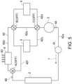
- the cooling system 40 is comprised of the radiator 2 (heat exchanger), the electric pump 41, a coolant circuit 42, and a deaeration tank 43 (see Fig. 4 ) for removing air contained in the coolant. Note that, in Figs. 5 , and 8 to 11 which will be described later, illustration of the deaeration tank 43 is omitted for simplification.
- the cooling system 40 circulatingly supplies the coolant cooled by the radiator 2 to each electric device to cool the electric device.
- upstream in the coolant-sending direction of the coolant may be referred to as “upstream,” and downstream in the coolant-sending direction of the coolant may be referred to as “downstream.”
- the radiator 2 is a device which is provided to the coolant circuit 42 and cools the coolant.
- the radiator 2 is disposed in a front end part of the vehicle 1 so that it extends in the vehicle width direction.
- the radiator 2 opposes to a front grille 11 which covers a front end surface of the vehicle 1.
- a front grille 11 which covers a front end surface of the vehicle 1.
- the radiator 2 cools the coolant by carrying out heat exchange with external air.
- the electric pump 41 is a device for sending the coolant into the coolant circuit 42, and although it is not intended to limit thereto, it is a non-positive displacement pump in detail.
- the electric pump 41 is connected with a part of the coolant circuit 42 upstream of the radiator 2 via piping. When the electric pump 41 operates, the coolant circulates through the coolant circuit 42 in a direction illustrated by an arrow f of a one-dot chain line in Fig. 5 .
- the electric pump 41 operates according to control of the control device 10.
- a command value for example, a duty ratio
- the electric pump 41 is controlled to operate with the output used as the reference, when the cooling system 40 is used (so-called "on-off control").
- the coolant used for the cooling system 40 is not limited in particular, and it may adopt known coolant commonly used for automobile cooling systems.
- the coolant may adopt so-called "antifreeze solution” which includes water and ethylene glycol, and does not freeze even below 0°C (e.g., -30°C).
- the antifreeze solution has viscosity higher than water, and the viscosity increases as the temperature decreases.
- the coolant circuit 42 is comprised of piping which is connected to the drive unit 60 and the charger 8 and through which the coolant flows.
- the coolant circuit 42 includes a first route 42a, a second route 42b, a third route 42c, a fourth route 42d, a fifth route 42e, a sixth route 42f (bypass route), and selector valves A, B, and C which change between the routes.
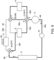
- Fig. 5 illustrates a state where the operation of the vehicle 1 is stopped and the high-voltage battery 6 is not currently charged (i.e., a non-used state of the cooling system 40). That is, the electric pump 41 is not in operation, and the selector valves A, B, and Care all in the OFF state.
- the drive motor 3 On the first route 42a, the drive motor 3, the electric pump 41, and the radiator 2 are disposed.
- the coolant which passed the drive motor 3 is configured to send the coolant to the radiator 2 via the electric pump 41.
- a downstream part of the first route 42a branches for the second route 42b and the sixth route 42f, and the selector valve A is provided at the branch point.
- the selector valve A selects either one of the second route 42b and the sixth route 42f as a route connected to a downstream end of the first route 42a.
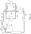
- the selector valve A is in the ON state, the coolant is sent to the second route 42b, and is not sent to the sixth route 42f (see Figs. 8 , 10 , and 11 ).
- the selector valve A is in the OFF state, the coolant is sent to the sixth route 42f, and is not sent to the second route 42b (see Fig. 9 ).
- the charger 8 is disposed in the second route 42b. As described above, the radiator 2 and the drive unit 60 are disposed in the front part of the vehicle 1. Contrarily, the charger 8 is disposed rearward of the drive unit 60 (i.e., in the rear part of the vehicle 1). Therefore, as illustrated in Fig. 4 , the second route 42b is comprised of a pair of piping which extend in the front-and-rear direction below the cabin 1a of the vehicle 1.
- a downstream part of the second route 42b branches for the third route 42c and the fourth route 42d, and the selector valve B is provided at the branch point.
- the selector valve B selects either one of the third route 42c and the fourth route 42d as a route connected to a downstream end of the second route 42b.
- the selector valve B is in the ON state, the coolant is sent to the third route 42c (see Figs. 8 and 10 ).
- the selector valve B is in the OFF state, the coolant is sent to the fourth route 42d (see Fig. 11 ).
- the converter 5 and the inverter 4 are disposed in the third route 42c and the fourth route 42d, respectively. That is, when the selector valve B is in the ON state, the coolant which passed through the charger 8 is sent to the converter 5. When the selector valve B is in the OFF state, the coolant which passed through the charger 8 is sent to the inverter 4.
- the fifth route 42e is also connected to the branch point where the selector valve B is provided, the coolant will not be directly sent from the second route 42b to the fifth route 42e.
- the fourth route 42d is connected to the fifth route 42e.
- the third route 42c is connected to the fifth route 42e.
- Downstream parts of the third route 42c and the fourth route 42d are connected to an upstream end of the first route 42a, and the selector valve C is provided at the junction. Because of the selector valve C, either one of the third route 42c and the fourth route 42d becomes a route connected to the upstream end of the first route 42a.
- the selector valve C when the selector valve C is in the ON state, a route through which the coolant flows from the third route 42c to the first route 42a is formed (see Figs. 8 and 11 ).
- the selector valve C is in the OFF state, a route through which the coolant flows from the fourth route 42d to the first route 42a is formed (see Figs. 9 and 10 ).
- the fifth route 42e is also connected to the junction where the selector valve C is provided, the coolant will not directly be sent from the fifth route 42e to the first route 42a.
- the fourth route 42d is connected to the fifth route 42e.
- the third route 42c is connected to the fifth route 42e.
- the second route 42b, the third route 42c, the fifth route 42e, the fourth route 42d, and the first route 42a are connected in this order (third state D3 which will be described later; see Fig. 10 ).
- This route connects the charger 8, the converter 5, the inverter 4, and the drive motor 3 in series in this order.
- the coolant passes through the charger 8, the converter 5, and the inverter 4 in this order, and is then sent to the drive motor 3.
- the second route 42b, the fourth route 42d, the fifth route 42e, the third route 42c, and the first route 42a are connected in this order (fourth state D4 which will be described later; see Fig. 11 ).
- This route connects the charger 8, the inverter 4, the converter 5, and the drive motor 3 in series in this order.
- the coolant passes through the charger 8, the inverter 4, and the converter 5 in this order, and is then sent to the drive motor 3.
- the coolant sending order of the inverter 4 and the converter 5 is changeable by changing the selector valves A, B, and C.
- the sixth route 42f is a route which bypasses the charger 8, and its downstream part is connected to an intermediate part of the third route 42c.
- the sixth route 42f may be piping which is disposed inside the motor room 1b.
- the coolant circuit 42 is provided with a coolant temperature sensor 44 which detects a temperature of the coolant.
- the coolant temperature sensor 44 is disposed, for example, downstream of the drive motor 3 where the temperature of the circulating coolant becomes the highest.
- the control device 10 is mounted on the vehicle 1.
- the control device 10 is comprised of hardware, such as a CPU, a RAM, and a ROM, and software, such as a control program implemented in the hardware.
- the control device 10 comprehensively controls the traveling of the vehicle 1.
- the control device 10 is provided with a pump controller 10a which controls the electric pump 41, a selector valve controller 10b which controls the selector valves A, B, and C, and a motor controller 10c which controls the operation of the drive motor 3 by using the inverter 4, as functional configurations.
- Signals are inputted into the control device 10 from various sensors, such as the converter temperature sensor 45, the inverter temperature sensor 46, the charger temperature sensor 47, and the coolant temperature sensor 44, which are described above. Note that these temperature sensors may detect temperature indirectly from electric current etc.
- the motor controller 10c of the control device 10 controls the inverter 4 based on the signal inputted from the converter temperature sensor 45 etc. For example, the control device 10 determines the abnormality in the temperature of the converter 5 based on the signal inputted from the converter temperature sensor 45. As a result, when the control device 10 determines that the temperature is abnormal, the control device 10 performs a control to limit the output of the drive motor 3.
- the pump controller 10a and the selector valve controller 10b of the control device 10 control the electric pump 41 and the selector valves A, B, and C, etc. to control the circulation of the coolant to the coolant circuit 42 based on the signals inputted from the converter temperature sensor 45, the inverter temperature sensor 46, the charger temperature sensor 47, and the coolant temperature sensor 44. That is, the control device 10 suitably operates the cooling system 40 so that the electric devices, such as the inverter 4, the converter 5, the drive motor 3, and the charger 8, which are the cooling targets, do not become abnormal in the temperature.
- the drive motor 3 and the inverter 4 do not operate.
- the charge to the high-voltage battery 6 is performed during the shutdown of the vehicle 1.
- the charger 8 operates.
- the converter 5 may operate according to the electric power state of the low-voltage power supply system 15 during the shutdown.
- the drive motor 3 and the inverter 4 operate.
- the converter 5 operates according to the electric power state of the low-voltage power supply system 15, when the capacity of the low-voltage battery 7 drops.
- the charger 8 does not operate when the vehicle 1 is operating.
- the cooling system 40 is also used in connection therewith.
- the electric pump 41 operates in order to cool these devices.
- the charger 8 and the converter 5 operate according to the situation to generate heat, the electric pump 41 operates in order to cool these devices.
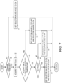
- Fig. 7 illustrates one example of a control flow of the cooling system 40.
- Step S 1 it is determined whether the charger 8 is in a condition where it is being used.
- the selector valves A, B, and C are set to the ON state (first state D1) so that the coolant flows into the second route 42b, as illustrated in Figs. 7 and 8 .
- the coolant is sent to and cools the charger 8 so that it suppresses an excessive rise in the temperature of the charger 8.
- the coolant which passed through the charger 8 is sent to the converter 5 by setting the selector valves B and C to the ON state.
- the converter 5 can also be cooled.
- the drive motor 3 is not in the operating condition, since the drive motor 3 has the largest calorific value among the electric devices included in the drive unit 60, it is configured so that the coolant is always sent during the operation of the cooling system 40.
- the coolant circuit 42 may be configured so that the coolant bypasses the drive motor 3 when the drive motor 3 is not in operation, the configuration of this embodiment is preferred in terms of reducing branches of the coolant circuit 42.
- Step S3 it is determined whether at least one of the temperature T I/V of the inverter 4 and the temperature T DCDC of the converter 5 is above a given temperature.
- both the temperature T I/V of the inverter 4 and the temperature T DCDC of the converter 5 become below given temperature.
- the selector valves A and C are set to the OFF state and the selector valve B to the ON state (second state D2).
- the coolant is sent to the sixth route 42f, and the coolant is prevented from flowing into the second route 42b. Therefore, the path length of the coolant circuit 42 can be shortened to reduce the load of the electric pump 41.
- the sixth route 42f is connected to a part of the coolant circuit 42 upstream of the converter 5 so that the coolant sent to the sixth route 42f is sent to the converter 5.
- the coolant is sent to the inverter 4 through the selector valves C and B, and is further sent to the drive motor 3 through the selector valve C.
- the calorific value which may be generated in these electric devices is the smallest in the converter 5, and the inverter 4 and the drive motor 3 have larger calorific values in this order.
- the coolant is desirable to be sent in this order. Note that, since a difference in the calorific value between the converter 5 and the inverter 4 during the normal traveling is not large, the coolant sending order may be reversed.
- Step S3 if at least one of the temperature T I/V of the inverter 4 and the temperature T DCDC of the converter 5 is determined to be above the given temperature, it transits to Step S4. Then, it is determined whether the temperature T I/V of the inverter 4 is higher than the temperature T DCDC of the converter 5.
- the calorific value of the converter 5 increases. Then, the temperature T DCDC of the converter 5 becomes above the temperature T I/V of the inverter 4 (in other words, the temperature T I/V of the inverter 4 becomes below the temperature T DCDC of the converter 5). Then, it becomes necessary to strengthen the cooling of the converter 5.
- the selector valves A and B are set to the ON state, and the selector valve C to the OFF state (the third state D3). Therefore, the coolant is sent through the selector valve A to the second route 42b (i.e., to the charger 8). Then, after the coolant is sent to the converter 5 through the selector valve B, and sent to the inverter 4 through the selector valves C and B, the coolant is sent to the drive motor 3 again through the selector valve C.
- the present inventors found out that, since the charger 8 is disposed rearward of the drive unit 20, the charger 8 is also capable of serving, so to speak, as a second radiator, by making the coolant circulate to the charger 8, also when not charging.
- this configuration can strengthen the cooling of the converter 5 by sending the coolant to the converter 5 after sending to the charger 8.
- the cooling fin 83 which projects downward and outward of the vehicle 1 is provided to the charger 8. Therefore, it can further reduce the temperature of the coolant by using the traveling wind of the vehicle 1 to contribute to the cooling of the converter 5.
- the calorific value of the inverter 4 increases. Then, the temperature T I/V of the inverter 4 becomes higher than the temperature T DCDC of the converter 5. Then, it becomes necessary to strengthen the cooling of the inverter 4.
- the selector valves A and C are set to the ON state, and the selector valve B to the OFF state (the fourth state D4). Therefore, the coolant is sent through the selector valve A to the second route 42b (i.e., to the charger 8). Then, after the coolant is sent to the inverter 4 through the selector valve B, and to the converter 5 through the selector valves C and B, the coolant is sent to the drive motor 3 again through the selector valve C.
- the load of the electric pump 41 can be reduced by making a detour of the coolant circulation to the charger 8, when the temperatures of the inverter 4 and the converter 5 are below the given temperature, while the charger 8 is not in operation.
- the coolant is intentionally sent to the charger 8 so that the charger 8 functions, so to speak, as the second radiator, and the cooling of the inverter 4 or converter 5 can be strengthened. In this way, according to this configuration, both the reduction in the pump load and the improvement in the cooling of the drive unit can be achieved.
- the coolant is first sent to the higher-temperature electric device.
- the coolant is sent to the inverter 4 after the coolant is sent to the converter 5 with a higher temperature.
- the coolant is sent to the converter 5 after the coolant is sent to the inverter 4 with a higher temperature.
- the coolant sending order to the electric devices is changeable according to the temperatures of the inverter 4 and the converter 5. Therefore, the highly-efficient cooling according to the priority of cooling the electric devices is possible.
- the coolant is sent to the electric devices in an ascending order of the calorific value.
- the calorific values of the inverter 4 and the converter 5 increase other than when the vehicle is in the normal traveling state.
- the internal structures of the inverter 4 and the converter 5 are similar, it is rare for the temperature difference to become extremely large even if both the temperatures are above the given temperature. Therefore, according to this configuration, the coolant is first send to the electric device with the higher temperature to effectively cool the electric device of which the cooling needs to be strengthened.
- a conventional cooling system 400 illustrated in Fig. 14 the coolant sent to a coolant circuit 142 by an electric pump 141 passes through a converter 105, an inverter 104, a charger 108, and a drive motor 103 in this order, after passing through a radiator 102.
- the layout of each electric device in the vehicle is similar to the layout of Fig. 1 .
- the temperature difference of the coolant (water) before and after passing through each electric device during the normal traveling at 100km/h is illustrated in Fig. 12 .
- data illustrated by solid lines are actual measurements, and data illustrated by a broken line is a calculated value. Note that, during the normal traveling, the converter 105, the inverter 104, and the drive motor 103 are in an active state, but the charger 108 is in an inactive state.
- the heat release amount and the thermal resistance of the charger 108 are calculated based on the results of Fig. 12 in consideration of the ambient temperature, they are about 100W and about 4.8K/W, respectively.
- the thermal resistance of the charger 108 decreases to about 2.4K/W. Then, it can be predicted that the heat release amount of the charger 108 increases to about 550W.
- Fig. 13 illustrates a relationship (calculation result) between the heat release amount of the charger 108 and the difference in the coolant temperature. As illustrated in Fig. 13 , it is predicted that, when the heat release amount of the charger 108 increases from about 100W to about 550W, the temperature of the coolant which passed through the charger 108 drops by about 1°C. This calculation result is illustrated in Fig. 12 by the broken line.
- the cooling fin is disposed so as to project to the outside of the vehicle as illustrated in Fig. 3 , it can be predicted that the heat release amount of the charger 108 further increases, and the function of the charger 108 as the second radiator further improves.
- the installed position of the charger 8 is not limited to the trunk floor 1c, as long as it is rearward of the drive unit 60.
- the charger 8 may not be provided with the cooling fin 83. Further, if the charger 8 is provided with the cooling fin 83, the cooling fin 83 may not project to the outside the vehicle.
- the charger 8 is more desirable to be disposed so that the main body 81 is located inside the vehicle 1 and the cooling fin 83 projects to the outside of the vehicle, regardless of the installed location of the charger 8.
- a fan capable of ventilating the charger 8 may be provided.
- the coolant sending order of the drive motor 3 and the electric pump 41 may be reversed. That is, the coolant circuit 42 may be configured so that the coolant passes through the drive motor 3 after passing through the electric pump 41.
- the temperature sensor may be provided, for example, to a casing of the drive motor 3, and may detect a temperature of the casing surface of the drive motor 3 as the temperature of the drive motor 3.
- the cooling system 40 may be in the non-used state ( Fig. 5 ).
- the vehicle 1 may be a range extender EV, for example.
- the vehicle 1 includes a range extender module in which the engine, the generator, and the converter are integrated.
- the engine is for power generation.
- the generator generates power by receiving the motive force of the engine.
- the converter is connected to the generator and the high-voltage battery 6, and it converts alternate current generated by the generator into direct current, and charges the high-voltage battery 6.
- the generator and the converter included in the range extender module may also be disposed in the coolant circuit 42 as the electric devices included in the drive unit 60.
- the present disclosure provides the electric vehicle cooling system capable of achieving both the reduction in the pump load and the improvement in the cooling of the drive unit, and it is therefore very useful.
Applications Claiming Priority (1)
| Application Number | Priority Date | Filing Date | Title |
|---|---|---|---|
| JP2022061858A JP2023151968A (ja) | 2022-04-01 | 2022-04-01 | 電動車両用冷却システム |
Publications (1)
| Publication Number | Publication Date |
|---|---|
| EP4253129A1 true EP4253129A1 (fr) | 2023-10-04 |
Family
ID=85776119
Family Applications (1)
| Application Number | Title | Priority Date | Filing Date |
|---|---|---|---|
| EP23164236.4A Pending EP4253129A1 (fr) | 2022-04-01 | 2023-03-27 | Système de refroidissement de véhicule électrique |
Country Status (4)
| Country | Link |
|---|---|
| US (1) | US20230311638A1 (fr) |
| EP (1) | EP4253129A1 (fr) |
| JP (1) | JP2023151968A (fr) |
| CN (1) | CN116890628A (fr) |
Citations (4)
| Publication number | Priority date | Publication date | Assignee | Title |
|---|---|---|---|---|
| CN104960411A (zh) * | 2015-05-21 | 2015-10-07 | 北汽福田汽车股份有限公司 | 用于电动车辆的冷却循环系统和具有其的电动车辆 |
| CN109878325A (zh) * | 2018-12-29 | 2019-06-14 | 北京新能源汽车技术创新中心有限公司 | 电动车冷却系统、电动车及电动车冷却系统控制方法 |
| JP2021030810A (ja) | 2019-08-21 | 2021-03-01 | マツダ株式会社 | 電気駆動車両の冷却装置 |
| US20210184294A1 (en) * | 2019-12-16 | 2021-06-17 | Ford Global Technologies, Llc | Electrified vehicle thermal management systems with combinable battery pack and electric drive component cooling circuits |
-
2022
- 2022-04-01 JP JP2022061858A patent/JP2023151968A/ja active Pending
-
2023
- 2023-02-17 CN CN202310130988.2A patent/CN116890628A/zh active Pending
- 2023-03-23 US US18/188,718 patent/US20230311638A1/en active Pending
- 2023-03-27 EP EP23164236.4A patent/EP4253129A1/fr active Pending
Patent Citations (4)
| Publication number | Priority date | Publication date | Assignee | Title |
|---|---|---|---|---|
| CN104960411A (zh) * | 2015-05-21 | 2015-10-07 | 北汽福田汽车股份有限公司 | 用于电动车辆的冷却循环系统和具有其的电动车辆 |
| CN109878325A (zh) * | 2018-12-29 | 2019-06-14 | 北京新能源汽车技术创新中心有限公司 | 电动车冷却系统、电动车及电动车冷却系统控制方法 |
| JP2021030810A (ja) | 2019-08-21 | 2021-03-01 | マツダ株式会社 | 電気駆動車両の冷却装置 |
| US20210184294A1 (en) * | 2019-12-16 | 2021-06-17 | Ford Global Technologies, Llc | Electrified vehicle thermal management systems with combinable battery pack and electric drive component cooling circuits |
Also Published As
| Publication number | Publication date |
|---|---|
| US20230311638A1 (en) | 2023-10-05 |
| JP2023151968A (ja) | 2023-10-16 |
| CN116890628A (zh) | 2023-10-17 |
Similar Documents
| Publication | Publication Date | Title |
|---|---|---|
| US11479145B2 (en) | Electric storage device for providing electric energy for a charging operation of at least one electrically-driven motor vehicle, and retrofit module and operating method | |
| JP4244991B2 (ja) | ハイブリッド自動車 | |
| US7377237B2 (en) | Cooling system for hybrid power system | |
| JP5257220B2 (ja) | 電池システム | |
| JP5769386B2 (ja) | 電気推進装置およびこれを備えた電動車両 | |
| JP2008135281A (ja) | 二次電池の充放電制御装置、および、それを備える車両 | |
| JP2009171702A (ja) | 車両駆動システム | |
| CN112977168A (zh) | 具有可组合的电池组和电驱动部件冷却回路的电动化车辆热管理系统 | |
| KR20200079055A (ko) | 모듈화된 전기자동차용 통합제어시스템 | |
| CN114435189A (zh) | 具有电池旁路回路的电动化车辆热管理系统 | |
| CN102729834B (zh) | 车辆供电设备 | |
| JP2009254206A (ja) | 電源制御システム | |
| US20080060370A1 (en) | Method of cooling a hybrid power system | |
| EP4253129A1 (fr) | Système de refroidissement de véhicule électrique | |
| US11695292B2 (en) | Power supply system for mobile body | |
| JP2015033182A (ja) | 半導体電力変換器の冷却システム | |
| US11728666B2 (en) | Power supply system | |
| US20220314730A1 (en) | Vehicle thermal management system | |
| JP7400261B2 (ja) | 車両の電気系冷却システム | |
| EP4113704A1 (fr) | Système de refroidissement et procédé de commande d'un système de refroidissement | |
| US20220302735A1 (en) | Power supply system | |
| US20220297572A1 (en) | Power supply system | |
| JP7237682B2 (ja) | 車両用電源装置 | |
| JP2022125582A (ja) | 電動車両の冷却装置 | |
| CN116176218A (zh) | 热管理控制器、热管理控制方法、电子设备和车辆 |
Legal Events
| Date | Code | Title | Description |
|---|---|---|---|
| PUAI | Public reference made under article 153(3) epc to a published international application that has entered the european phase |
Free format text: ORIGINAL CODE: 0009012 |
|
| STAA | Information on the status of an ep patent application or granted ep patent |
Free format text: STATUS: THE APPLICATION HAS BEEN PUBLISHED |
|
| AK | Designated contracting states |
Kind code of ref document: A1 Designated state(s): AL AT BE BG CH CY CZ DE DK EE ES FI FR GB GR HR HU IE IS IT LI LT LU LV MC ME MK MT NL NO PL PT RO RS SE SI SK SM TR |
|
| STAA | Information on the status of an ep patent application or granted ep patent |
Free format text: STATUS: REQUEST FOR EXAMINATION WAS MADE |
|
| 17P | Request for examination filed |
Effective date: 20240402 |
|
| RBV | Designated contracting states (corrected) |
Designated state(s): AL AT BE BG CH CY CZ DE DK EE ES FI FR GB GR HR HU IE IS IT LI LT LU LV MC ME MK MT NL NO PL PT RO RS SE SI SK SM TR |