EP4252950A1 - Electrochemical machining device - Google Patents
Electrochemical machining device Download PDFInfo
- Publication number
- EP4252950A1 EP4252950A1 EP21897951.6A EP21897951A EP4252950A1 EP 4252950 A1 EP4252950 A1 EP 4252950A1 EP 21897951 A EP21897951 A EP 21897951A EP 4252950 A1 EP4252950 A1 EP 4252950A1
- Authority
- EP
- European Patent Office
- Prior art keywords
- electrode
- electric discharge
- electrochemical machining
- machining apparatus
- machined
- Prior art date
- Legal status (The legal status is an assumption and is not a legal conclusion. Google has not performed a legal analysis and makes no representation as to the accuracy of the status listed.)
- Pending
Links
Images






Classifications
-
- B—PERFORMING OPERATIONS; TRANSPORTING
- B23—MACHINE TOOLS; METAL-WORKING NOT OTHERWISE PROVIDED FOR
- B23H—WORKING OF METAL BY THE ACTION OF A HIGH CONCENTRATION OF ELECTRIC CURRENT ON A WORKPIECE USING AN ELECTRODE WHICH TAKES THE PLACE OF A TOOL; SUCH WORKING COMBINED WITH OTHER FORMS OF WORKING OF METAL
- B23H3/00—Electrochemical machining, i.e. removing metal by passing current between an electrode and a workpiece in the presence of an electrolyte
- B23H3/10—Supply or regeneration of working media
-
- B—PERFORMING OPERATIONS; TRANSPORTING
- B23—MACHINE TOOLS; METAL-WORKING NOT OTHERWISE PROVIDED FOR
- B23H—WORKING OF METAL BY THE ACTION OF A HIGH CONCENTRATION OF ELECTRIC CURRENT ON A WORKPIECE USING AN ELECTRODE WHICH TAKES THE PLACE OF A TOOL; SUCH WORKING COMBINED WITH OTHER FORMS OF WORKING OF METAL
- B23H11/00—Auxiliary apparatus or details, not otherwise provided for
- B23H11/003—Mounting of workpieces, e.g. working-tables
-
- B—PERFORMING OPERATIONS; TRANSPORTING
- B23—MACHINE TOOLS; METAL-WORKING NOT OTHERWISE PROVIDED FOR
- B23H—WORKING OF METAL BY THE ACTION OF A HIGH CONCENTRATION OF ELECTRIC CURRENT ON A WORKPIECE USING AN ELECTRODE WHICH TAKES THE PLACE OF A TOOL; SUCH WORKING COMBINED WITH OTHER FORMS OF WORKING OF METAL
- B23H3/00—Electrochemical machining, i.e. removing metal by passing current between an electrode and a workpiece in the presence of an electrolyte
- B23H3/04—Electrodes specially adapted therefor or their manufacture
-
- B—PERFORMING OPERATIONS; TRANSPORTING
- B23—MACHINE TOOLS; METAL-WORKING NOT OTHERWISE PROVIDED FOR
- B23H—WORKING OF METAL BY THE ACTION OF A HIGH CONCENTRATION OF ELECTRIC CURRENT ON A WORKPIECE USING AN ELECTRODE WHICH TAKES THE PLACE OF A TOOL; SUCH WORKING COMBINED WITH OTHER FORMS OF WORKING OF METAL
- B23H7/00—Processes or apparatus applicable to both electrical discharge machining and electrochemical machining
- B23H7/26—Apparatus for moving or positioning electrode relatively to workpiece; Mounting of electrode
- B23H7/28—Moving electrode in a plane normal to the feed direction, e.g. orbiting
-
- B—PERFORMING OPERATIONS; TRANSPORTING
- B23—MACHINE TOOLS; METAL-WORKING NOT OTHERWISE PROVIDED FOR
- B23H—WORKING OF METAL BY THE ACTION OF A HIGH CONCENTRATION OF ELECTRIC CURRENT ON A WORKPIECE USING AN ELECTRODE WHICH TAKES THE PLACE OF A TOOL; SUCH WORKING COMBINED WITH OTHER FORMS OF WORKING OF METAL
- B23H9/00—Machining specially adapted for treating particular metal objects or for obtaining special effects or results on metal objects
- B23H9/10—Working turbine blades or nozzles
-
- B—PERFORMING OPERATIONS; TRANSPORTING
- B23—MACHINE TOOLS; METAL-WORKING NOT OTHERWISE PROVIDED FOR
- B23H—WORKING OF METAL BY THE ACTION OF A HIGH CONCENTRATION OF ELECTRIC CURRENT ON A WORKPIECE USING AN ELECTRODE WHICH TAKES THE PLACE OF A TOOL; SUCH WORKING COMBINED WITH OTHER FORMS OF WORKING OF METAL
- B23H2400/00—Moving mechanisms for tool electrodes
- B23H2400/10—Moving mechanisms for tool electrodes for rotating the electrode
Definitions
- the present invention relates to an electrochemical machining apparatus.
- Japanese Patent Application Laying-Open No. 01-222820 (PTL 1) is a prior art document disclosing a configuration of an apparatus to electrochemically machine an impeller.
- the electrochemical machining apparatus described in PTL 1 comprises a pair of generally vaned machining electrodes having a vane machining surface.
- the workpiece is pivoted about the X axis.
- the workpiece is rotated about the Z axis by one pitch and thus positioned.
- the electrochemical machining apparatus described in PTL 1 forms a plurality of vanes by electrochemical machining, one by one, by the pair of machining electrodes, and hence consumes a long period of time to do so. Further, as the apparatus machines the vanes one by one, the plurality of vanes may be machined with variation in precision.
- the present invention has been made in view of the above issue, and an object of the present invention is to provide an electrochemical machining apparatus capable of machining an impeller with high precision in a reduced period of time.
- An electrochemical machining apparatus is an electrochemical machining apparatus that electrochemically machines an impeller circumferentially having a plurality of roughly molded vanes.
- the electrochemical machining apparatus comprises a support, a rotary shaft, and a plurality of electric discharge electrodes.
- the support supports the impeller.
- the rotary shaft holds the support rotatably.
- the plurality of electric discharge electrodes are disposed at equal intervals along a circumference about the rotary shaft, and provided so as to be capable of being brought into and out of contact with the plurality of vanes such that one electric discharge electrode corresponds to one vane.
- the plurality of electric discharge electrodes each have an electrode surface along a surface to be machined of a corresponding one of the plurality of vanes. After the plurality of electric discharge electrodes each move radially inward toward the rotary shaft, the rotary shaft rotates and electrochemical machining is thus performed while the electrode surface and the surface to be machined are close to and thus face each other.
- the electrochemical machining apparatus further comprises a plurality of nozzles.
- the plurality of nozzles are each disposed adjacent to a corresponding one of the plurality of electric discharge electrodes.
- the plurality of nozzles each have a discharge port to discharge an electrolytic solution between the electrode surface and the surface to be machined.
- the plurality of nozzles each have a concave portion on a side surface thereof that is located at an end portion thereof closer to the discharge port and faces away from the electrode surface.
- the support is detachably connected to the rotary shaft.
- the electrochemical machining apparatus further comprises a plurality of electrode holders and a plurality of positioning plates.
- the plurality of electrode holders hold the plurality of electric discharge electrodes such that one electrode holder corresponds to one electric discharge electrode.
- the plurality of positioning plates position the plurality of electric discharge electrodes on the plurality of electrode holders such that one positioning plate corresponds to one electric discharge electrode on one electrode holder.
- the plurality of electric discharge electrodes are each detachably connected to a corresponding one of the plurality of electrode holders.
- the present invention allows an impeller to be machined with high precision in a reduced period of time.
- an electrochemical machining apparatus 100 is an electrochemical machining apparatus that electrochemically machines an impeller 10 circumferentially having a plurality of roughly molded vanes 11.
- the impeller 10 is made for example of a titanium alloy.
- the impeller 10 before it is electrochemically machined is roughly molded for example by casting.
- the impeller 10 is used, for example, as a turbine wheel.
- the plurality of vanes 11 each have a twisted and also curved surface to be machined 12.
- the impeller 10 has nine vanes 11.
- the impeller 10 may not have nine vanes 11 and may have a plurality of vanes 11 other than nine vanes.
- the electrochemical machining apparatus 100 comprises a support 110, a rotary shaft 120, and a plurality of electric discharge electrodes 130.
- the support 110 detachably supports the impeller 10.
- the rotary shaft 120 holds the support 110 rotatably.
- the support 110 is detachably connected to the rotary shaft 120.
- the rotary shaft 120 is connected to a rotation drive unit (not shown).
- the plurality of electric discharge electrodes 130 are disposed at equal intervals along a circumference about the rotary shaft 120, and provided so as to be capable of being brought into and out of contact with the plurality of vanes 11 such that one electric discharge electrode corresponds to one vane.
- the electrochemical machining apparatus 100 comprises nine electric discharge electrodes 130.
- One electric discharge electrode 130 is disposed so as to be able to come into and out of contact with one vane 11.
- the electric discharge electrode 130 has an electrode surface 131 along the surface to be machined 12 of the vane 11. That is, the plurality of electric discharge electrodes 130 each have the electrode surface 131 along the surface to be machined 12 of a corresponding one of the plurality of vanes 11.
- the electrode surface 131 is twisted and also curved.
- the electrochemical machining apparatus 100 further comprises a plurality of electrode holders 170 and a plurality of positioning plates 140.
- the electric discharge electrode 130 is held by the electrode holder 170 so as to be movable radially about the rotary shaft 120.
- the plurality of electrode holders 170 hold the plurality of electric discharge electrodes 130 such that one electrode holder corresponds to one electric discharge electrode.
- the electrochemical machining apparatus 100 comprises nine electrode holders 170.
- the nine electrode holders 170 are each provided so as to be capable of sliding linearly.
- the plurality of electric discharge electrodes 130 are each detachably connected to a corresponding one of the plurality of electrode holders 170.
- the electric discharge electrode 130 is provided with a through hole.
- the electric discharge electrode 130 is fastened to the electrode holder 170 with a bolt 160 inserted through the through hole.
- An insulating plate 150 is disposed on an upper surface of each of the plurality of electrode holders 170.
- the electric discharge electrode 130 and the electrode holder 170 are electrically insulated from each other by the insulating plate 150.
- the insulating plate 150 is made for example of an insulating resin such as epoxy resin.
- the positioning plate 140 is fixed on the insulating plate 150.
- the positioning plate 140 has a flat upper surface on which the electric discharge electrode 130 is mounted, a side wall in contact with a side surface of the electric discharge electrode 130, and a rear wall in contact with an end surface of a base side of the electric discharge electrode 130.
- the electric discharge electrode 130 placed on the upper surface of the positioning plate 140 is positioned on the electrode holder 170 by being disposed such that the side wall of the positioning plate 140 and the side surface of the electric discharge electrode 130 are in contact with each other and the rear wall of the positioning plate 140 and the end surface of the base side of the electric discharge electrode 130 are in contact with each other.
- the plurality of positioning plates 140 position the plurality of electric discharge electrodes 130 on the plurality of electrode holders 170 such that one positioning plate corresponds to one electric discharge electrode on one electrode holder.
- the electric discharge electrode 130 can be positionally, finely adjusted by a shim inserted into a gap between the electric discharge electrode 130 and the positioning plate 140.
- the electrode surface 131 of the electric discharge electrode 130 positioned on the electrode holder 170 is located at a position spaced from and facing the surface to be machined 12 of the impeller 10 to be machined when the electric discharge electrode 130 moves radially inward toward the rotary shaft 120, as will be described later.
- the electrochemical machining apparatus 100 further comprises a linear drive unit 180 that drives the electrode holder 170 radially about the rotary shaft 120.
- a linear drive unit 180 that drives the electrode holder 170 radially about the rotary shaft 120.
- nine linear drive units 180 are provided, and each linear drive unit 180 is connected to one electrode holder 170.
- the electrochemical machining apparatus 100 further comprises a clamp mechanism 190.
- the clamp mechanism 190 is provided so as to be movable in a vertical direction, and can press and clamp from above the impeller 10 supported by the support 110.
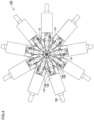
- Fig. 4 is a plan view of a state in which the electrochemical machining apparatus according to an embodiment of the present invention has the plurality of electric discharge electrodes each moved radially inward toward the rotary shaft.
- Fig. 4 shows the electric discharge electrodes 130 alone moved radially inward toward the rotary shaft.
- the linear drive unit 180 drives to cause the electrode holder 170 to approach the impeller 10
- the electric discharge electrode 130 moves radially inward toward the rotary shaft 120, as shown in Fig. 4 .
- the electrode surface 131 of the electric discharge electrode 130 faces the surface to be machined 12 of the vane 11 to be machined, with a gap therebetween.
- the rotary shaft 120 is rotated by the rotation drive unit in a direction indicated by an arrow R shown in Fig. 2 , and the electrode surface 131 and the surface to be machined 12 thus approach and face each other.
- the electrode surfaces 131 of the nine electric discharge electrodes 130 approach and thus face the surfaces to be machined 12 of the nine vanes 11 concurrently such that one electrode surface corresponds to one surface to be machined.
- a voltage is applied to the electric discharge electrode 130 to perform electrical discharge machining.
- the vane 11 having undergone electrical discharge machining is smaller in thickness than the roughly molded vane and has the surface 12 machined and smoothened in surface roughness.
- the electrochemical machining apparatus 100 further comprises a first nozzle 134 and a second nozzle 136 which are configured to be attachable to the electric discharge electrode 130 and integrated therewith, and detachable from the electric discharge electrode 130.
- the electric discharge electrode 130 is composed of a conductive member.
- the first and second nozzles 134 and 136 are each made of an insulating resin such as epoxy resin.
- the first nozzle 134 is disposed adjacent to the electric discharge electrode 130.
- nine first nozzles 134 are each disposed adjacent to a corresponding one of the nine electric discharge electrodes 130.
- the first nozzle 134 has a first discharge port 132 that discharges an electrolytic solution between the electrode surface 131 and the surface to be machined 12 along the electrode surface 131 while the electrode surface 131 and the surface to be machined 12 are close to and face each other, as shown in Fig. 4 .
- the first discharge port 132 has a shape along the electrode surface 131, as seen at a front side.
- the first nozzle 134 has a concave portion 135 on a side surface thereof that is located at an end portion thereof closer to the first discharge port 132 and faces away from the electrode surface 131.
- the second nozzle 136 is disposed above the electric discharge electrode 130.
- the second nozzle 136 has a second discharge port 133 that discharges an electrolytic solution between the electrode surface 131 and the surface to be machined 12 from above while the electrode surface 131 and the surface to be machined 12 are close to and face each other, as shown in Fig. 4 .
- the second nozzle 136 is curved at a curved portion 137, as seen from above, and the second discharge port 133 is located above the electrode surface 131.
- the second discharge port 133 has a shape along the electrode surface 131 when seen from below.
- the electric discharge electrode 130 has a body 130a engaged with each of the first and second nozzles 134 and 136.
- the first nozzle 134 has a first engagement portion 134a which has a channel formed therein to pass an electrolytic solution toward the first discharge port 132 and engages with the body 130a.
- the electric discharge electrode 130 and the first nozzle 134 are configured integrally such that they are attachable to and detachable from each other.
- Fig. 10 is a plan view of a configuration of the first nozzle according to a first variation.
- a first nozzle 234 according to the first variation includes an inlet 231 which receives an electrolytic solution, and a first engagement portion 234a which has a channel formed therein to pass the electrolytic solution toward the first discharge port 132 and engages with the body 130a.
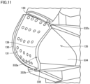
- Fig. 11 is a partial perspective view of the first discharge port of the first nozzle and a vicinity thereof of the electrochemical machining apparatus according to a second variation, as seen at a front side.
- the electrochemical machining apparatus according to the second variation has a first nozzle 334 with a first discharge port 332 composed of a wall surface 139 of the electric discharge electrode 130 contiguous to the electrode surface 131, a surface 332a of the first nozzle 334 spaced from and facing the wall surface 139, and a first connection surface 332b and a second connection surface 332c interconnecting the wall surface 139 and the surface 332a.
- an electrolytic solution discharged through the first discharge port 332 of the first nozzle 334 can be supplied between the electrode surface 131 and the surface to be machined 12 from the wall surface 139 continuously along the electrode surface 131. This allows the electrolytic solution to be supplied between the electrode surface 131 and the surface to be machined 12 in a more uniform distribution and allows the impeller 10 to be machined with high precision.
- Fig. 12 is a partial perspective view of the second discharge port of the second nozzle and a vicinity thereof of the electrochemical machining apparatus according to a third variation, as seen from below.
- the electrochemical machining apparatus comprises a second nozzle 436 having a second discharge port 433 that is generally in the form of a circle when seen from below.
- the second discharge port 433 has an opening larger in area than that of the second discharge port 133 according to one embodiment. This allows the second discharge port 433 to discharge an electrolytic solution at a reduced flow velocity to supply the electrolytic solution between the electrode surface 131 and the surface to be machined 12 mainly where the electrolytic solution discharged through the first discharge port 132 does not easily reach.
- the electrochemical machining apparatus 100 is an electrochemical machining apparatus that electrochemically machines the impeller 10 circumferentially having a plurality of roughly molded vanes 11, and after the plurality of electric discharge electrodes 130 each move radially inward toward the rotary shaft 120, the rotary shaft 120 rotates and electrochemical machining is thus performed while the electrode surface 131 and the surface to be machined 12 are close to and thus face each other.
- This allows the impeller 10 to have the plurality of roughly molded vanes 11 electrochemically machined simultaneously and hence in a reduced period of time, and also suppresses variation caused in precision in machining the plurality of vanes 11 and thus allows the impeller 10 to be machined with high precision.
- the first nozzle 134 disposed adjacent to the electric discharge electrode 130 has the first discharge port 132 that discharges an electrolytic solution between the electrode surface 131 and the surface to be machined 12 along the electrode surface 131. This allows the electrolytic solution to be supplied between the electrode surface 131 and the surface to be machined 12 in a uniform distribution and allows the impeller 10 to be machined with high precision.
- the first nozzle 134 has a concave portion 135 on a side surface thereof that is located at an end portion thereof closer to the first discharge port 132 and faces away from the electrode surface 131. As shown in Fig. 4 , in a state with the electrode surface 131 and the surface to be machined 12 close to and facing each other, the concave portion 135 can suppress interference between an adjacent electric discharge electrode 130 and the first nozzle 134.
- the support 110 is detachably connected to the rotary shaft 120. This allows only a support 110 damaged by electrochemical machining to be removed from the rotary shaft 120 and replaced with another support.
- the second nozzle 136 disposed above the electric discharge electrode 130 has the second discharge port 133 that discharges an electrolytic solution between the electrode surface 131 and the surface to be machined 12 from above. This allows the electrolytic solution to be supplied between the electrode surface 131 and the surface to be machined 12 in a more uniform distribution and allows the impeller 10 to be machined with high precision.
- the electric discharge electrode 130 and the first nozzle 134 are configured integrally such that they are attachable to and detachable from each other.
- the former facilitates manufacturing the electric discharge electrode 130 and the first nozzle 134 and allows only an electric discharge electrode 130 damaged by electrochemical machining to be replaced with another.
- the electric discharge electrode 130 and the second nozzle 136 are configured integrally such that they are attachable to and detachable from each other.
- the former facilitates manufacturing the electric discharge electrode 130 and the second nozzle 136 and allows only an electric discharge electrode 130 damaged by electrochemical machining to be replaced with another.
- the second nozzle 136 is curved at the curved portion 137 when seen from above, and the second discharge port 133 is located above the electrode surface 131. This can suppress interference between adjacent second nozzles 136 while the electrode surface 131 and the surface to be machined 12 are close to and face each other, as shown in Fig. 4 .
- a rectifying mechanism is provided to at least one of a channel of the first nozzle 234 for an electrolytic solution toward the first discharge port 132 and a channel of the second nozzle 136 for an electrolytic solution toward the second discharge port 133. This allows at least one of the first discharge port 132 and the second discharge port 133 to discharge an electrolytic solution in a uniform distribution to supply the electrolytic solution between the electrode surface 131 and the surface to be machined 12 in a more uniform distribution to machine the impeller 10 with high precision.
- the first nozzle 334 has the first discharge port 332 composed of the wall surface 139 of the electric discharge electrode 130 contiguous to the electrode surface 131, the surface 332a of the first nozzle 334 spaced from and facing the wall surface 139, and the first connection surface 332b and the second connection surface 332c interconnecting the wall surface 139 and the surface 332a.
- an electrolytic solution discharged through the first discharge port 332 of the first nozzle 334 can be supplied between the electrode surface 131 and the surface to be machined 12 continuously from the wall surface 139 along the electrode surface 131 in a more uniform distribution, and the impeller 10 can be machined with high precision.
- the second nozzle 436 has the second discharge port 433 generally in the form of a circle when seen from below, and having an opening with a relatively large area. This allows the second discharge port 433 to discharge an electrolytic solution at a reduced flow velocity to supply the electrolytic solution between the electrode surface 131 and the surface to be machined 12 mainly where the electrolytic solution discharged through the first discharge port 132 does not easily reach.
Landscapes
- Engineering & Computer Science (AREA)
- Mechanical Engineering (AREA)
- Chemical & Material Sciences (AREA)
- Chemical Kinetics & Catalysis (AREA)
- Electrochemistry (AREA)
- Physics & Mathematics (AREA)
- Thermal Sciences (AREA)
- Manufacturing & Machinery (AREA)
- Electrical Discharge Machining, Electrochemical Machining, And Combined Machining (AREA)
Abstract
Description
- The present invention relates to an electrochemical machining apparatus.
-
Japanese Patent Application Laying-Open No. 01-222820 - PTL 1:
Japanese Patent Laying-Open No. 1-222820 - The electrochemical machining apparatus described in PTL 1 forms a plurality of vanes by electrochemical machining, one by one, by the pair of machining electrodes, and hence consumes a long period of time to do so. Further, as the apparatus machines the vanes one by one, the plurality of vanes may be machined with variation in precision.
- The present invention has been made in view of the above issue, and an object of the present invention is to provide an electrochemical machining apparatus capable of machining an impeller with high precision in a reduced period of time.
- An electrochemical machining apparatus according to the present invention is an electrochemical machining apparatus that electrochemically machines an impeller circumferentially having a plurality of roughly molded vanes. The electrochemical machining apparatus comprises a support, a rotary shaft, and a plurality of electric discharge electrodes. The support supports the impeller. The rotary shaft holds the support rotatably. The plurality of electric discharge electrodes are disposed at equal intervals along a circumference about the rotary shaft, and provided so as to be capable of being brought into and out of contact with the plurality of vanes such that one electric discharge electrode corresponds to one vane. The plurality of electric discharge electrodes each have an electrode surface along a surface to be machined of a corresponding one of the plurality of vanes. After the plurality of electric discharge electrodes each move radially inward toward the rotary shaft, the rotary shaft rotates and electrochemical machining is thus performed while the electrode surface and the surface to be machined are close to and thus face each other.
- In one embodiment of the present invention, the electrochemical machining apparatus further comprises a plurality of nozzles. The plurality of nozzles are each disposed adjacent to a corresponding one of the plurality of electric discharge electrodes. The plurality of nozzles each have a discharge port to discharge an electrolytic solution between the electrode surface and the surface to be machined. The plurality of nozzles each have a concave portion on a side surface thereof that is located at an end portion thereof closer to the discharge port and faces away from the electrode surface.
- In one aspect of the present invention, the support is detachably connected to the rotary shaft. In one embodiment of the present invention, the electrochemical machining apparatus further comprises a plurality of electrode holders and a plurality of positioning plates. The plurality of electrode holders hold the plurality of electric discharge electrodes such that one electrode holder corresponds to one electric discharge electrode. The plurality of positioning plates position the plurality of electric discharge electrodes on the plurality of electrode holders such that one positioning plate corresponds to one electric discharge electrode on one electrode holder.
- In one aspect of the present invention, the plurality of electric discharge electrodes are each detachably connected to a corresponding one of the plurality of electrode holders.
- The present invention allows an impeller to be machined with high precision in a reduced period of time.
-
-
Fig. 1 is a plan view of a state before an electrochemical machining apparatus according to an embodiment of the present invention starts machining. -
Fig. 2 is a perspective view of a configuration of the electrochemical machining apparatus ofFig. 1 . -
Fig. 3 is a longitudinal cross section showing a configuration of the electrochemical machining apparatus ofFig. 2 . -
Fig. 4 is a plan view of a state in which the electrochemical machining apparatus according to an embodiment of the present invention has a plurality of electric discharge electrodes each moved radially inward toward a rotary shaft. -
Fig. 5 is a perspective view of a configuration of an electric discharge electrode, and a first nozzle and a second nozzle comprised in the electrochemical machining apparatus according to an embodiment of the present invention. -
Fig. 6 is a front view of theFig. 5 electric discharge electrode and first and second nozzles, as seen in a direction of an arrow VI. -
Fig. 7 is a perspective view of a configuration of an electric discharge electrode comprised in the electrochemical machining apparatus according to an embodiment of the present invention. -
Fig. 8 is a perspective view of a configuration of the first nozzle comprised in the electrochemical machining apparatus according to an embodiment of the present invention. -
Fig. 9 is a perspective view of a configuration of the second nozzle comprised in the electrochemical machining apparatus according to an embodiment of the present invention. -
Fig. 10 is a plan view of a configuration of the first nozzle according to a first variation. -
Fig. 11 is a partial perspective view of a first discharge port of the first nozzle and a vicinity thereof of the electrochemical machining apparatus according to a second variation, as seen at a front side. -
Fig. 12 is a partial perspective view of a second discharge port of the second nozzle and a vicinity thereof of the electrochemical machining apparatus according to a third variation, as seen from below. - Hereinafter, an electrochemical machining apparatus according to an embodiment of the present invention will be described with reference to the accompanying drawings. In the following description, identical or corresponding components in the figures are identically denoted and will not be described repeatedly in detail.
-
Fig. 1 is a plan view of a state before the electrochemical machining apparatus according to the embodiment of the present invention starts machining.Fig. 2 is a perspective view of a configuration of the electrochemical machining apparatus ofFig. 1 .Fig. 3 is a longitudinal cross section showing the configuration of the electrochemical machining apparatus ofFig. 2 .Figs. 1 and3 do not show a clamp mechanism, which will be described later.Figs. 2 and3 only show one electric discharge electrode of a plurality of electric discharge electrodes. - As shown in
Figs. 1 to 3 , anelectrochemical machining apparatus 100 according to an embodiment of the present invention is an electrochemical machining apparatus that electrochemically machines animpeller 10 circumferentially having a plurality of roughly moldedvanes 11. Theimpeller 10 is made for example of a titanium alloy. Theimpeller 10 before it is electrochemically machined is roughly molded for example by casting. Theimpeller 10 is used, for example, as a turbine wheel. The plurality ofvanes 11 each have a twisted and also curved surface to be machined 12. In the present embodiment, theimpeller 10 has ninevanes 11. However, theimpeller 10 may not have ninevanes 11 and may have a plurality ofvanes 11 other than nine vanes. - The
electrochemical machining apparatus 100 comprises asupport 110, arotary shaft 120, and a plurality ofelectric discharge electrodes 130. Thesupport 110 detachably supports theimpeller 10. Therotary shaft 120 holds thesupport 110 rotatably. Thesupport 110 is detachably connected to therotary shaft 120. Therotary shaft 120 is connected to a rotation drive unit (not shown). - The plurality of
electric discharge electrodes 130 are disposed at equal intervals along a circumference about therotary shaft 120, and provided so as to be capable of being brought into and out of contact with the plurality ofvanes 11 such that one electric discharge electrode corresponds to one vane. In the present embodiment, theelectrochemical machining apparatus 100 comprises nineelectric discharge electrodes 130. Oneelectric discharge electrode 130 is disposed so as to be able to come into and out of contact with onevane 11. - The
electric discharge electrode 130 has anelectrode surface 131 along the surface to be machined 12 of thevane 11. That is, the plurality ofelectric discharge electrodes 130 each have theelectrode surface 131 along the surface to be machined 12 of a corresponding one of the plurality ofvanes 11. Theelectrode surface 131 is twisted and also curved. - The
electrochemical machining apparatus 100 further comprises a plurality ofelectrode holders 170 and a plurality ofpositioning plates 140. Theelectric discharge electrode 130 is held by theelectrode holder 170 so as to be movable radially about therotary shaft 120. The plurality ofelectrode holders 170 hold the plurality ofelectric discharge electrodes 130 such that one electrode holder corresponds to one electric discharge electrode. In the present embodiment, theelectrochemical machining apparatus 100 comprises nineelectrode holders 170. The nineelectrode holders 170 are each provided so as to be capable of sliding linearly. - The plurality of
electric discharge electrodes 130 are each detachably connected to a corresponding one of the plurality ofelectrode holders 170. In the present embodiment, theelectric discharge electrode 130 is provided with a through hole. Theelectric discharge electrode 130 is fastened to theelectrode holder 170 with abolt 160 inserted through the through hole. - An insulating
plate 150 is disposed on an upper surface of each of the plurality ofelectrode holders 170. Theelectric discharge electrode 130 and theelectrode holder 170 are electrically insulated from each other by the insulatingplate 150. The insulatingplate 150 is made for example of an insulating resin such as epoxy resin. - The
positioning plate 140 is fixed on the insulatingplate 150. Thepositioning plate 140 has a flat upper surface on which theelectric discharge electrode 130 is mounted, a side wall in contact with a side surface of theelectric discharge electrode 130, and a rear wall in contact with an end surface of a base side of theelectric discharge electrode 130. - The
electric discharge electrode 130 placed on the upper surface of thepositioning plate 140 is positioned on theelectrode holder 170 by being disposed such that the side wall of thepositioning plate 140 and the side surface of theelectric discharge electrode 130 are in contact with each other and the rear wall of thepositioning plate 140 and the end surface of the base side of theelectric discharge electrode 130 are in contact with each other. In other words, the plurality ofpositioning plates 140 position the plurality ofelectric discharge electrodes 130 on the plurality ofelectrode holders 170 such that one positioning plate corresponds to one electric discharge electrode on one electrode holder. Theelectric discharge electrode 130 can be positionally, finely adjusted by a shim inserted into a gap between theelectric discharge electrode 130 and thepositioning plate 140. - The
electrode surface 131 of theelectric discharge electrode 130 positioned on theelectrode holder 170 is located at a position spaced from and facing the surface to be machined 12 of theimpeller 10 to be machined when theelectric discharge electrode 130 moves radially inward toward therotary shaft 120, as will be described later. - The
electrochemical machining apparatus 100 further comprises alinear drive unit 180 that drives theelectrode holder 170 radially about therotary shaft 120. In the present embodiment, ninelinear drive units 180 are provided, and eachlinear drive unit 180 is connected to oneelectrode holder 170. - As shown in
Fig. 2 , theelectrochemical machining apparatus 100 further comprises aclamp mechanism 190. Theclamp mechanism 190 is provided so as to be movable in a vertical direction, and can press and clamp from above theimpeller 10 supported by thesupport 110. -
Fig. 4 is a plan view of a state in which the electrochemical machining apparatus according to an embodiment of the present invention has the plurality of electric discharge electrodes each moved radially inward toward the rotary shaft.Fig. 4 shows theelectric discharge electrodes 130 alone moved radially inward toward the rotary shaft. - When the
linear drive unit 180 drives to cause theelectrode holder 170 to approach theimpeller 10, theelectric discharge electrode 130 moves radially inward toward therotary shaft 120, as shown inFig. 4 . As a result, theelectrode surface 131 of theelectric discharge electrode 130 faces the surface to be machined 12 of thevane 11 to be machined, with a gap therebetween. - Subsequently, the
rotary shaft 120 is rotated by the rotation drive unit in a direction indicated by an arrow R shown inFig. 2 , and theelectrode surface 131 and the surface to be machined 12 thus approach and face each other. In the present embodiment, the electrode surfaces 131 of the nineelectric discharge electrodes 130 approach and thus face the surfaces to be machined 12 of the ninevanes 11 concurrently such that one electrode surface corresponds to one surface to be machined. In this state, a voltage is applied to theelectric discharge electrode 130 to perform electrical discharge machining. Thevane 11 having undergone electrical discharge machining is smaller in thickness than the roughly molded vane and has thesurface 12 machined and smoothened in surface roughness. - Hereinafter, a configuration of the
electric discharge electrode 130 in theelectrochemical machining apparatus 100 according to the present embodiment will be described in detail. -
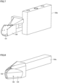
Fig. 5 is a perspective view of a configuration of an electric discharge electrode, and a first nozzle and a second nozzle comprised in the electrochemical machining apparatus according to an embodiment of the present invention.Fig. 6 is a front view of theFig. 5 electric discharge electrode and first and second nozzles, as seen in a direction of an arrow VI.Fig. 7 is a perspective view of a configuration of an electric discharge electrode comprised in the electrochemical machining apparatus according to an embodiment of the present invention.Fig. 8 is a perspective view of a configuration of the first nozzle comprised in the electrochemical machining apparatus according to an embodiment of the present invention.Fig. 9 is a perspective view of a configuration of the second nozzle comprised in the electrochemical machining apparatus according to an embodiment of the present invention. - As shown in
Figs. 5 to 9 , theelectrochemical machining apparatus 100 further comprises afirst nozzle 134 and asecond nozzle 136 which are configured to be attachable to theelectric discharge electrode 130 and integrated therewith, and detachable from theelectric discharge electrode 130. Theelectric discharge electrode 130 is composed of a conductive member. The first andsecond nozzles - Note, however, that the
electric discharge electrode 130 and the first andsecond nozzles electric discharge electrode 130 and the first andsecond nozzles - As shown in
Figs. 5 and6 , thefirst nozzle 134 is disposed adjacent to theelectric discharge electrode 130. In the present embodiment, ninefirst nozzles 134 are each disposed adjacent to a corresponding one of the nineelectric discharge electrodes 130. - The
first nozzle 134 has afirst discharge port 132 that discharges an electrolytic solution between theelectrode surface 131 and the surface to be machined 12 along theelectrode surface 131 while theelectrode surface 131 and the surface to be machined 12 are close to and face each other, as shown inFig. 4 . Thefirst discharge port 132 has a shape along theelectrode surface 131, as seen at a front side. Thefirst nozzle 134 has aconcave portion 135 on a side surface thereof that is located at an end portion thereof closer to thefirst discharge port 132 and faces away from theelectrode surface 131. - The
second nozzle 136 is disposed above theelectric discharge electrode 130. Thesecond nozzle 136 has asecond discharge port 133 that discharges an electrolytic solution between theelectrode surface 131 and the surface to be machined 12 from above while theelectrode surface 131 and the surface to be machined 12 are close to and face each other, as shown inFig. 4 . Thesecond nozzle 136 is curved at acurved portion 137, as seen from above, and thesecond discharge port 133 is located above theelectrode surface 131. Thesecond discharge port 133 has a shape along theelectrode surface 131 when seen from below. - As shown in
Fig. 7 , theelectric discharge electrode 130 has abody 130a engaged with each of the first andsecond nozzles Fig. 8 , thefirst nozzle 134 has afirst engagement portion 134a which has a channel formed therein to pass an electrolytic solution toward thefirst discharge port 132 and engages with thebody 130a. Theelectric discharge electrode 130 and thefirst nozzle 134 are configured integrally such that they are attachable to and detachable from each other. - As shown in
Fig. 9 , thesecond nozzle 136 has asecond engagement portion 136a which has a channel formed therein to pass an electrolytic solution toward thesecond discharge port 133 and engages with thebody 130a. Theelectric discharge electrode 130 and thesecond nozzle 136 are configured integrally such that they are attachable to and detachable from each other. -
Fig. 10 is a plan view of a configuration of the first nozzle according to a first variation. As shown inFig. 10 , afirst nozzle 234 according to the first variation includes aninlet 231 which receives an electrolytic solution, and afirst engagement portion 234a which has a channel formed therein to pass the electrolytic solution toward thefirst discharge port 132 and engages with thebody 130a. - The channel of the
first nozzle 234 that passes the electrolytic solution is provided with a rectifying mechanism. In the first variation, thefirst nozzle 234 is provided with a first narrowedportion 232 and a second narrowedportion 233. Thus, the channel in thefirst nozzle 234 to pass the electrolytic solution meanders between theinlet 231 and thefirst discharge port 132, and theinlet 231 and thefirst discharge port 132 do not communicate linearly. The rectifying mechanism is not limited in configuration to a narrowed portion, and a configuration allowing thefirst discharge port 132 to discharge the electrolytic solution in a uniform distribution suffices. The rectifying mechanism may be provided to thesecond nozzle 136. When the rectifying mechanism is provided to thesecond nozzle 136, thesecond discharge port 133 can discharge an electrolytic solution in a uniform distribution. -
Fig. 11 is a partial perspective view of the first discharge port of the first nozzle and a vicinity thereof of the electrochemical machining apparatus according to a second variation, as seen at a front side. As shown inFig. 11 , the electrochemical machining apparatus according to the second variation has afirst nozzle 334 with afirst discharge port 332 composed of awall surface 139 of theelectric discharge electrode 130 contiguous to theelectrode surface 131, asurface 332a of thefirst nozzle 334 spaced from and facing thewall surface 139, and afirst connection surface 332b and asecond connection surface 332c interconnecting thewall surface 139 and thesurface 332a. - In the second variation, an electrolytic solution discharged through the
first discharge port 332 of thefirst nozzle 334 can be supplied between theelectrode surface 131 and the surface to be machined 12 from thewall surface 139 continuously along theelectrode surface 131. This allows the electrolytic solution to be supplied between theelectrode surface 131 and the surface to be machined 12 in a more uniform distribution and allows theimpeller 10 to be machined with high precision. -
Fig. 12 is a partial perspective view of the second discharge port of the second nozzle and a vicinity thereof of the electrochemical machining apparatus according to a third variation, as seen from below. As shown inFig. 12 , according to the third variation, the electrochemical machining apparatus comprises asecond nozzle 436 having asecond discharge port 433 that is generally in the form of a circle when seen from below. Thesecond discharge port 433 has an opening larger in area than that of thesecond discharge port 133 according to one embodiment. This allows thesecond discharge port 433 to discharge an electrolytic solution at a reduced flow velocity to supply the electrolytic solution between theelectrode surface 131 and the surface to be machined 12 mainly where the electrolytic solution discharged through thefirst discharge port 132 does not easily reach. - The
electrochemical machining apparatus 100 according to one embodiment of the present invention is an electrochemical machining apparatus that electrochemically machines theimpeller 10 circumferentially having a plurality of roughly moldedvanes 11, and after the plurality ofelectric discharge electrodes 130 each move radially inward toward therotary shaft 120, therotary shaft 120 rotates and electrochemical machining is thus performed while theelectrode surface 131 and the surface to be machined 12 are close to and thus face each other. This allows theimpeller 10 to have the plurality of roughly moldedvanes 11 electrochemically machined simultaneously and hence in a reduced period of time, and also suppresses variation caused in precision in machining the plurality ofvanes 11 and thus allows theimpeller 10 to be machined with high precision. - In the
electrochemical machining apparatus 100 according to an embodiment of the present invention, thefirst nozzle 134 disposed adjacent to theelectric discharge electrode 130 has thefirst discharge port 132 that discharges an electrolytic solution between theelectrode surface 131 and the surface to be machined 12 along theelectrode surface 131. This allows the electrolytic solution to be supplied between theelectrode surface 131 and the surface to be machined 12 in a uniform distribution and allows theimpeller 10 to be machined with high precision. - In the
electrochemical machining apparatus 100 according to an embodiment of the present invention, thefirst nozzle 134 has aconcave portion 135 on a side surface thereof that is located at an end portion thereof closer to thefirst discharge port 132 and faces away from theelectrode surface 131. As shown inFig. 4 , in a state with theelectrode surface 131 and the surface to be machined 12 close to and facing each other, theconcave portion 135 can suppress interference between an adjacentelectric discharge electrode 130 and thefirst nozzle 134. - In the
electrochemical machining apparatus 100 according to an embodiment of the present invention, thesupport 110 is detachably connected to therotary shaft 120. This allows only asupport 110 damaged by electrochemical machining to be removed from therotary shaft 120 and replaced with another support. - In the
electrochemical machining apparatus 100 according to an embodiment of the present invention, thepositioning plate 140 positions theelectric discharge electrode 130 on theelectrode holder 170. This can reduce variation in a positional relationship between theelectrode surface 131 and the surface to be machined 12, and thus allows theimpeller 10 to be machined with high precision. Further, theelectric discharge electrode 130 can be positionally, finely adjusted by a shim inserted into a gap between theelectric discharge electrode 130 and thepositioning plate 140. - In the
electrochemical machining apparatus 100 according to an embodiment of the present invention, theelectric discharge electrode 130 is detachably connected to theelectrode holder 170. This allows only anelectric discharge electrode 130 damaged by electrochemical machining to be removed from theelectrode holder 170 and replaced with another electric discharge electrode. - In the
electrochemical machining apparatus 100 according to an embodiment of the present invention, thesecond nozzle 136 disposed above theelectric discharge electrode 130 has thesecond discharge port 133 that discharges an electrolytic solution between theelectrode surface 131 and the surface to be machined 12 from above. This allows the electrolytic solution to be supplied between theelectrode surface 131 and the surface to be machined 12 in a more uniform distribution and allows theimpeller 10 to be machined with high precision. - In the
electrochemical machining apparatus 100 according to an embodiment of the present invention, theelectric discharge electrode 130 and thefirst nozzle 134 are configured integrally such that they are attachable to and detachable from each other. When this is compared with theelectric discharge electrode 130 and thefirst nozzle 134 integrally formed inseparably, the former facilitates manufacturing theelectric discharge electrode 130 and thefirst nozzle 134 and allows only anelectric discharge electrode 130 damaged by electrochemical machining to be replaced with another. - In the
electrochemical machining apparatus 100 according to an embodiment of the present invention, theelectric discharge electrode 130 and thesecond nozzle 136 are configured integrally such that they are attachable to and detachable from each other. When this is compared with theelectric discharge electrode 130 and thesecond nozzle 136 integrally formed inseparably, the former facilitates manufacturing theelectric discharge electrode 130 and thesecond nozzle 136 and allows only anelectric discharge electrode 130 damaged by electrochemical machining to be replaced with another. - In the
electrochemical machining apparatus 100 according to an embodiment of the present invention, thesecond nozzle 136 is curved at thecurved portion 137 when seen from above, and thesecond discharge port 133 is located above theelectrode surface 131. This can suppress interference between adjacentsecond nozzles 136 while theelectrode surface 131 and the surface to be machined 12 are close to and face each other, as shown inFig. 4 . - In the electrochemical machining apparatus according to a first variation, a rectifying mechanism is provided to at least one of a channel of the
first nozzle 234 for an electrolytic solution toward thefirst discharge port 132 and a channel of thesecond nozzle 136 for an electrolytic solution toward thesecond discharge port 133. This allows at least one of thefirst discharge port 132 and thesecond discharge port 133 to discharge an electrolytic solution in a uniform distribution to supply the electrolytic solution between theelectrode surface 131 and the surface to be machined 12 in a more uniform distribution to machine theimpeller 10 with high precision. - In the electrochemical machining apparatus according to a second variation, the
first nozzle 334 has thefirst discharge port 332 composed of thewall surface 139 of theelectric discharge electrode 130 contiguous to theelectrode surface 131, thesurface 332a of thefirst nozzle 334 spaced from and facing thewall surface 139, and thefirst connection surface 332b and thesecond connection surface 332c interconnecting thewall surface 139 and thesurface 332a. Thus, an electrolytic solution discharged through thefirst discharge port 332 of thefirst nozzle 334 can be supplied between theelectrode surface 131 and the surface to be machined 12 continuously from thewall surface 139 along theelectrode surface 131 in a more uniform distribution, and theimpeller 10 can be machined with high precision. - In the electrochemical machining apparatus according to a third variation, the
second nozzle 436 has thesecond discharge port 433 generally in the form of a circle when seen from below, and having an opening with a relatively large area. This allows thesecond discharge port 433 to discharge an electrolytic solution at a reduced flow velocity to supply the electrolytic solution between theelectrode surface 131 and the surface to be machined 12 mainly where the electrolytic solution discharged through thefirst discharge port 132 does not easily reach. - It should be understood that the presently disclosed embodiments are illustrative and non-restrictive in any respect. The scope of the present invention is defined by the terms of the claims, rather than the above description, and is intended to include any modifications within the meaning and scope equivalent to the terms of the claims.
- 10 impeller, 11 vane, 12 surface to be machined, 100 electrochemical machining apparatus, 110 support, 120 rotary shaft, 130 electric discharge electrode, 130a body, 131 electrode surface, 132, 332, first discharge port, 133, 433, second discharge port, 134, 234, 334, first nozzle, 134a, 234a first engagement portion, 135 concave portion, 136, 436, second nozzle, 136a second engagement portion, 137 curved portion, 139 wall surface, 140 positioning plate, 150 insulating plate, 160 bolt, 170 electrode holder, 180 linear drive unit, 190 clamp mechanism, 231 inlet, 232 first narrowed portion, 233 second narrowed portion, 332a facing surface, 332b first connection surface, 332c second connection surface.
Claims (5)
- An electrochemical machining apparatus that electrochemically machines an impeller circumferentially having a plurality of roughly molded vanes, comprising:a support that supports the impeller;a rotary shaft that holds the support rotatably; anda plurality of electric discharge electrodes disposed at equal intervals along a circumference about the rotary shaft, and provided so as to be capable of being brought into and out of contact with the plurality of vanes such that one electric discharge electrode corresponds to one vane; whereinthe plurality of electric discharge electrodes each have an electrode surface along a surface to be machined of a corresponding one of the plurality of vanes, andafter the plurality of electric discharge electrodes each move radially inward toward the rotary shaft, the rotary shaft rotates and electrochemical machining is thus performed while the electrode surface and the surface to be machined are close to and thus face each other.
- The electrochemical machining apparatus according to claim 1, further comprising a plurality of nozzles each disposed adjacent to a corresponding one of the plurality of electric discharge electrodes and having a discharge port to discharge an electrolytic solution between the electrode surface and the surface to be machined, wherein the plurality of nozzles each have a concave portion on a side surface thereof that is located at an end portion thereof closer to the discharge port and faces away from the electrode surface.
- The electrochemical machining apparatus according to claim 1 or 2, wherein the support is detachably connected to the rotary shaft.
- The electrochemical machining apparatus according to any one of claims 1 to 3, further comprising:a plurality of electrode holders that hold the plurality of electric discharge electrodes such that one electrode holder corresponds to one electric discharge electrode; anda plurality of positioning plates that position the plurality of electric discharge electrodes on the plurality of electrode holders such that one positioning plate corresponds to one electric discharge electrode on one electrode holder.
- The electrochemical machining apparatus according to claim 4, wherein the plurality of electric discharge electrodes are each detachably connected to a corresponding one of the plurality of electrode holders.
Applications Claiming Priority (2)
| Application Number | Priority Date | Filing Date | Title |
|---|---|---|---|
| JP2020195145A JP7435422B2 (en) | 2020-11-25 | 2020-11-25 | Electrolytic processing equipment |
| PCT/JP2021/042925 WO2022113979A1 (en) | 2020-11-25 | 2021-11-24 | Electrochemical machining device |
Publications (2)
| Publication Number | Publication Date |
|---|---|
| EP4252950A1 true EP4252950A1 (en) | 2023-10-04 |
| EP4252950A4 EP4252950A4 (en) | 2024-12-18 |
Family
ID=81756032
Family Applications (1)
| Application Number | Title | Priority Date | Filing Date |
|---|---|---|---|
| EP21897951.6A Pending EP4252950A4 (en) | 2020-11-25 | 2021-11-24 | DEVICE FOR ELECTROCHEMICAL PROCESSING |
Country Status (5)
| Country | Link |
|---|---|
| US (1) | US20230405699A1 (en) |
| EP (1) | EP4252950A4 (en) |
| JP (1) | JP7435422B2 (en) |
| CN (1) | CN116547095B (en) |
| WO (1) | WO2022113979A1 (en) |
Families Citing this family (1)
| Publication number | Priority date | Publication date | Assignee | Title |
|---|---|---|---|---|
| CN119387730B (en) * | 2024-12-17 | 2025-12-19 | 贵阳航发精密铸造有限公司 | Variable circulation blade cover plate groove machining device |
Family Cites Families (14)
| Publication number | Priority date | Publication date | Assignee | Title |
|---|---|---|---|---|
| JPS49106452A (en) * | 1973-02-15 | 1974-10-09 | ||
| US4851090A (en) * | 1987-05-13 | 1989-07-25 | General Electric Company | Method and apparatus for electrochemically machining airfoil blades |
| JPH0796166B2 (en) * | 1988-03-01 | 1995-10-18 | エーピーシーエアロスペシャルティ株式会社 | Electrolytic machining method and electrolytic machining apparatus for integrated impeller |
| US7204926B2 (en) * | 2001-11-26 | 2007-04-17 | General Electric Company | Tandem blisk electrochemical machining |
| DE102004051854A1 (en) * | 2004-10-26 | 2006-04-27 | Mtu Aero Engines Gmbh | Method and device for producing integrally bladed rotors |
| JP2007069328A (en) * | 2005-09-08 | 2007-03-22 | Ee P C Aero Specialty Kk | Electrochemical machining device |
| WO2011036924A1 (en) * | 2009-09-24 | 2011-03-31 | 三菱電機株式会社 | Wire electric discharge machining apparatus, wire electric discharge machining method, thin board manufacturing method and semiconductor wafer manufacturing method |
| JP2014007028A (en) * | 2012-06-22 | 2014-01-16 | Sharp Corp | Ion generating device |
| CN104275534A (en) * | 2014-09-10 | 2015-01-14 | 南京航空航天大学 | Electrolytic machining method for blisk through oblique swinging mode of spatial swivel feeding composite workpiece |
| DE102015102720A1 (en) * | 2015-02-25 | 2016-08-25 | Rolls-Royce Deutschland Ltd & Co Kg | Device for the electrochemical machining of blisks, tandems and blisk drums |
| US10300544B2 (en) * | 2016-05-23 | 2019-05-28 | General Electric Company | Machining and manufacturing systems and method of operating the same |
| JP3213091U (en) * | 2017-08-07 | 2017-10-19 | 株式会社エスエムケイ | Nut and bolt welding electrode holder |
| CN110328418B (en) * | 2019-05-29 | 2020-07-28 | 南京航空航天大学 | Liquid supply clamp for rotary printing electrolytic machining and liquid supply mode thereof |
| DE102019213013A1 (en) * | 2019-08-29 | 2021-03-04 | MTU Aero Engines AG | ECM system with a recording and a processing platform |
-
2020
- 2020-11-25 JP JP2020195145A patent/JP7435422B2/en active Active
-
2021
- 2021-11-24 WO PCT/JP2021/042925 patent/WO2022113979A1/en not_active Ceased
- 2021-11-24 EP EP21897951.6A patent/EP4252950A4/en active Pending
- 2021-11-24 US US18/252,237 patent/US20230405699A1/en active Pending
- 2021-11-24 CN CN202180077739.0A patent/CN116547095B/en active Active
Also Published As
| Publication number | Publication date |
|---|---|
| CN116547095A (en) | 2023-08-04 |
| CN116547095B (en) | 2025-11-25 |
| JP2022083677A (en) | 2022-06-06 |
| EP4252950A4 (en) | 2024-12-18 |
| JP7435422B2 (en) | 2024-02-21 |
| WO2022113979A1 (en) | 2022-06-02 |
| US20230405699A1 (en) | 2023-12-21 |
Similar Documents
| Publication | Publication Date | Title |
|---|---|---|
| EP3356075B1 (en) | Machining apparatus and machining system | |
| EP4252950A1 (en) | Electrochemical machining device | |
| US3970538A (en) | Apparatus for electro-chemical milling of turbine blade edges | |
| EP1524059B1 (en) | An apparatus and method for machining in confined spaces | |
| CN112864084A (en) | Wafer Holder | |
| EP2246139A1 (en) | An electrode discharge machining apparatus and method of machining a workpiece | |
| CN108883473B (en) | Cutting tool and method for machining annular groove | |
| JP7571496B2 (en) | Electrochemical Processing Equipment | |
| JPS62130125A (en) | Electrochemical processing equipment | |
| US11241749B2 (en) | Electrical discharge machining method and electrical discharge machining device | |
| US4687562A (en) | Anode assembly for selectively plating electrical terminals | |
| CN109278205B (en) | Cutting device and electrode terminal assembly | |
| JPH0592320A (en) | Wire electric discharge machine | |
| EP3287550B1 (en) | Device for vertical galvanic metal deposition on a substrate | |
| US4896013A (en) | Hyperboloid current pick-up for an electrical discharge wire cutting machine | |
| TW202144108A (en) | Electrolytic processing apparatus and method thereof | |
| JP2000190155A (en) | Hub blade | |
| RU2798858C1 (en) | Method and device for electroerosive processing of elongated workpieces | |
| CN223775268U (en) | A dispensing machine adjustment fixture | |
| JP4147722B2 (en) | EDM machine | |
| CN217371518U (en) | Compact machining clamp for thermostat shell | |
| CN220862938U (en) | Clamp for aligning and setting points in electric spark machining | |
| US3654122A (en) | Workpiece holding fixture for electrolytic shaping apparatus | |
| WO2011116826A1 (en) | A self-centering clamp for a cylindrical tool | |
| JPH0248377B2 (en) |
Legal Events
| Date | Code | Title | Description |
|---|---|---|---|
| STAA | Information on the status of an ep patent application or granted ep patent |
Free format text: STATUS: THE INTERNATIONAL PUBLICATION HAS BEEN MADE |
|
| PUAI | Public reference made under article 153(3) epc to a published international application that has entered the european phase |
Free format text: ORIGINAL CODE: 0009012 |
|
| STAA | Information on the status of an ep patent application or granted ep patent |
Free format text: STATUS: REQUEST FOR EXAMINATION WAS MADE |
|
| 17P | Request for examination filed |
Effective date: 20230516 |
|
| AK | Designated contracting states |
Kind code of ref document: A1 Designated state(s): AL AT BE BG CH CY CZ DE DK EE ES FI FR GB GR HR HU IE IS IT LI LT LU LV MC MK MT NL NO PL PT RO RS SE SI SK SM TR |
|
| DAV | Request for validation of the european patent (deleted) | ||
| DAX | Request for extension of the european patent (deleted) | ||
| P01 | Opt-out of the competence of the unified patent court (upc) registered |
Free format text: CASE NUMBER: APP_38603/2024 Effective date: 20240627 |
|
| A4 | Supplementary search report drawn up and despatched |
Effective date: 20241118 |
|
| RIC1 | Information provided on ipc code assigned before grant |
Ipc: B23H 3/04 20060101ALI20241112BHEP Ipc: B23H 11/00 20060101ALI20241112BHEP Ipc: B23H 7/28 20060101ALI20241112BHEP Ipc: B23H 3/10 20060101ALI20241112BHEP Ipc: B23H 9/10 20060101AFI20241112BHEP |