EP4252948A1 - Angetriebenes werkzeug und nachschleifbarer schneideinsatz dafür - Google Patents
Angetriebenes werkzeug und nachschleifbarer schneideinsatz dafür Download PDFInfo
- Publication number
- EP4252948A1 EP4252948A1 EP22165981.6A EP22165981A EP4252948A1 EP 4252948 A1 EP4252948 A1 EP 4252948A1 EP 22165981 A EP22165981 A EP 22165981A EP 4252948 A1 EP4252948 A1 EP 4252948A1
- Authority
- EP
- European Patent Office
- Prior art keywords
- relief
- edge
- cutting
- subsurface
- cutting insert
- Prior art date
- Legal status (The legal status is an assumption and is not a legal conclusion. Google has not performed a legal analysis and makes no representation as to the accuracy of the status listed.)
- Pending
Links
- 238000005520 cutting process Methods 0.000 title claims abstract description 218
- 230000002093 peripheral effect Effects 0.000 claims abstract description 13
- 230000007704 transition Effects 0.000 claims description 24
- 230000000295 complement effect Effects 0.000 claims description 8
- 230000007423 decrease Effects 0.000 claims description 8
- 230000001154 acute effect Effects 0.000 claims description 6
- 230000033001 locomotion Effects 0.000 claims description 5
- 238000000227 grinding Methods 0.000 description 18
- 238000000034 method Methods 0.000 description 10
- 238000003754 machining Methods 0.000 description 8
- 230000008569 process Effects 0.000 description 5
- 239000011248 coating agent Substances 0.000 description 3
- 238000000576 coating method Methods 0.000 description 3
- 238000004519 manufacturing process Methods 0.000 description 3
- 239000000463 material Substances 0.000 description 3
- 230000002787 reinforcement Effects 0.000 description 3
- 230000008859 change Effects 0.000 description 2
- 230000008878 coupling Effects 0.000 description 2
- 238000010168 coupling process Methods 0.000 description 2
- 238000005859 coupling reaction Methods 0.000 description 2
- 230000000694 effects Effects 0.000 description 2
- 238000010862 gear shaping Methods 0.000 description 2
- 239000002184 metal Substances 0.000 description 2
- 238000003801 milling Methods 0.000 description 2
- 230000009471 action Effects 0.000 description 1
- 238000006073 displacement reaction Methods 0.000 description 1
- 230000002349 favourable effect Effects 0.000 description 1
- 230000002035 prolonged effect Effects 0.000 description 1
- 238000007493 shaping process Methods 0.000 description 1
- 239000000126 substance Substances 0.000 description 1
Images


Classifications
-
- B—PERFORMING OPERATIONS; TRANSPORTING
- B23—MACHINE TOOLS; METAL-WORKING NOT OTHERWISE PROVIDED FOR
- B23F—MAKING GEARS OR TOOTHED RACKS
- B23F21/00—Tools specially adapted for use in machines for manufacturing gear teeth
- B23F21/04—Planing or slotting tools
- B23F21/043—Planing or slotting tools with inserted cutting elements
- B23F21/046—Planing or slotting tools with inserted cutting elements in exchangeable arrangement
-
- B—PERFORMING OPERATIONS; TRANSPORTING
- B23—MACHINE TOOLS; METAL-WORKING NOT OTHERWISE PROVIDED FOR
- B23C—MILLING
- B23C5/00—Milling-cutters
- B23C5/16—Milling-cutters characterised by physical features other than shape
- B23C5/20—Milling-cutters characterised by physical features other than shape with removable cutter bits or teeth or cutting inserts
- B23C5/22—Securing arrangements for bits or teeth or cutting inserts
- B23C5/2204—Securing arrangements for bits or teeth or cutting inserts with cutting inserts clamped against the walls of the recess in the cutter body by a clamping member acting upon the wall of a hole in the insert
- B23C5/2208—Securing arrangements for bits or teeth or cutting inserts with cutting inserts clamped against the walls of the recess in the cutter body by a clamping member acting upon the wall of a hole in the insert for plate-like cutting inserts
- B23C5/2213—Securing arrangements for bits or teeth or cutting inserts with cutting inserts clamped against the walls of the recess in the cutter body by a clamping member acting upon the wall of a hole in the insert for plate-like cutting inserts having a special shape
-
- B—PERFORMING OPERATIONS; TRANSPORTING
- B23—MACHINE TOOLS; METAL-WORKING NOT OTHERWISE PROVIDED FOR
- B23F—MAKING GEARS OR TOOTHED RACKS
- B23F21/00—Tools specially adapted for use in machines for manufacturing gear teeth
- B23F21/04—Planing or slotting tools
- B23F21/06—Planing or slotting tools having a profile which matches a gear tooth profile
- B23F21/063—Planing or slotting tools having a profile which matches a gear tooth profile with inserted cutting elements
- B23F21/066—Planing or slotting tools having a profile which matches a gear tooth profile with inserted cutting elements in exchangeable arrangement
-
- B—PERFORMING OPERATIONS; TRANSPORTING
- B23—MACHINE TOOLS; METAL-WORKING NOT OTHERWISE PROVIDED FOR
- B23F—MAKING GEARS OR TOOTHED RACKS
- B23F21/00—Tools specially adapted for use in machines for manufacturing gear teeth
- B23F21/04—Planing or slotting tools
- B23F21/10—Gear-shaper cutters having a shape similar to a spur wheel or part thereof
- B23F21/103—Gear-shaper cutters having a shape similar to a spur wheel or part thereof with inserted cutting elements
- B23F21/106—Gear-shaper cutters having a shape similar to a spur wheel or part thereof with inserted cutting elements in exchangeable arrangement
-
- B—PERFORMING OPERATIONS; TRANSPORTING
- B23—MACHINE TOOLS; METAL-WORKING NOT OTHERWISE PROVIDED FOR
- B23F—MAKING GEARS OR TOOTHED RACKS
- B23F21/00—Tools specially adapted for use in machines for manufacturing gear teeth
- B23F21/28—Shaving cutters
- B23F21/282—Shaving cutters with inserted cutting elements
- B23F21/284—Shaving cutters with inserted cutting elements in exchangeable arrangement
-
- B—PERFORMING OPERATIONS; TRANSPORTING
- B23—MACHINE TOOLS; METAL-WORKING NOT OTHERWISE PROVIDED FOR
- B23F—MAKING GEARS OR TOOTHED RACKS
- B23F5/00—Making straight gear teeth involving moving a tool relatively to a workpiece with a rolling-off or an enveloping motion with respect to the gear teeth to be made
- B23F5/12—Making straight gear teeth involving moving a tool relatively to a workpiece with a rolling-off or an enveloping motion with respect to the gear teeth to be made by planing or slotting
- B23F5/16—Making straight gear teeth involving moving a tool relatively to a workpiece with a rolling-off or an enveloping motion with respect to the gear teeth to be made by planing or slotting the tool having a shape similar to that of a spur wheel or part thereof
- B23F5/163—Making straight gear teeth involving moving a tool relatively to a workpiece with a rolling-off or an enveloping motion with respect to the gear teeth to be made by planing or slotting the tool having a shape similar to that of a spur wheel or part thereof the tool and workpiece being in crossed axis arrangement, e.g. skiving, i.e. "Waelzschaelen"
-
- B—PERFORMING OPERATIONS; TRANSPORTING
- B23—MACHINE TOOLS; METAL-WORKING NOT OTHERWISE PROVIDED FOR
- B23C—MILLING
- B23C2200/00—Details of milling cutting inserts
- B23C2200/16—Supporting or bottom surfaces
- B23C2200/165—Supporting or bottom surfaces with one or more grooves
-
- B—PERFORMING OPERATIONS; TRANSPORTING
- B23—MACHINE TOOLS; METAL-WORKING NOT OTHERWISE PROVIDED FOR
- B23C—MILLING
- B23C2200/00—Details of milling cutting inserts
- B23C2200/28—Angles
- B23C2200/293—Variable clearance angles
-
- B—PERFORMING OPERATIONS; TRANSPORTING
- B23—MACHINE TOOLS; METAL-WORKING NOT OTHERWISE PROVIDED FOR
- B23C—MILLING
- B23C2210/00—Details of milling cutters
- B23C2210/16—Fixation of inserts or cutting bits in the tool
- B23C2210/168—Seats for cutting inserts, supports for replacable cutting bits
Definitions
- said object is achieved by means of a cutting insert having the features defined in claim 1.
- each insert seat of the power skiving tool body may comprise a threaded hole, which facilitates mounting of the cutting insert using a fastening element, such as a screw.
- the nominal relief angle ( ⁇ ) in any second point along the cutting edge may be a function of the maximum value ( ⁇ max ) of the nominal relief angle and the acute angle ( ⁇ ) between a tangent to the cutting edge in said second point and a tangent to the cutting edge in the first point.
- the cutting insert is indexable and comprises a further cutting edge arranged in the first plane, wherein both cutting edges have identical, or substantially identical, cutting edge profiles and are arranged opposite to each other.
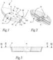
- the cutting insert 1 comprises a first side 2, a second side 3 and a peripheral surface 4.
- the first side 2 includes a rake face 5
- the peripheral surface 4 includes a relief surface 6 comprising a first relief subsurface 61, a second relief subsurface 62 and a corner relief subsurface 63.
- a cutting edge 7 is formed which includes a first flank edge 71, a second flank edge 72 and a nose edge 73.
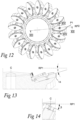
- the distance from the first plane P to the section plane illustrated in Fig. 6 corresponds to a maximum available grinding depth.
- the profile formed by an intersection between such section plane, on one hand, and the first relief subsurface 61, the second relief subsurface 62 and the corner relief subsurface 63 on the other hand will have a profile that is identical to the cutting edge profile. This will be true also for section planes located even further from the first plane P, at distances greater than the maximum grinding depth. It may nevertheless be inappropriate to re-grind the cutting insert beyond the defined maximum grinding depth, for example due to requirements to maintain a sufficient strength and robustness of the cutting insert.
- the maximum grinding depth is 3 mm. Accordingly, if each re-grind involves removing material to a depth of 0.3 mm, it will be possible to re-grind the cutting insert 10 times.
Priority Applications (2)
| Application Number | Priority Date | Filing Date | Title |
|---|---|---|---|
| EP22165981.6A EP4252948A1 (de) | 2022-03-31 | 2022-03-31 | Angetriebenes werkzeug und nachschleifbarer schneideinsatz dafür |
| PCT/EP2023/057347 WO2023186664A1 (en) | 2022-03-31 | 2023-03-22 | Power skiving tool and re-grindable cutting insert therefor |
Applications Claiming Priority (1)
| Application Number | Priority Date | Filing Date | Title |
|---|---|---|---|
| EP22165981.6A EP4252948A1 (de) | 2022-03-31 | 2022-03-31 | Angetriebenes werkzeug und nachschleifbarer schneideinsatz dafür |
Publications (1)
| Publication Number | Publication Date |
|---|---|
| EP4252948A1 true EP4252948A1 (de) | 2023-10-04 |
Family
ID=81326619
Family Applications (1)
| Application Number | Title | Priority Date | Filing Date |
|---|---|---|---|
| EP22165981.6A Pending EP4252948A1 (de) | 2022-03-31 | 2022-03-31 | Angetriebenes werkzeug und nachschleifbarer schneideinsatz dafür |
Country Status (2)
| Country | Link |
|---|---|
| EP (1) | EP4252948A1 (de) |
| WO (1) | WO2023186664A1 (de) |
Citations (5)
| Publication number | Priority date | Publication date | Assignee | Title |
|---|---|---|---|---|
| US20100003090A1 (en) * | 2008-07-07 | 2010-01-07 | Sandvik Intellectual Property Ab | Indexable milling insert |
| US20140010606A1 (en) * | 2012-07-05 | 2014-01-09 | Sandvik Intellectual Property Ab | Milling insert and a milling tool |
| EP2845675A2 (de) | 2013-08-27 | 2015-03-11 | Sandvik Intellectual Property AB | Werkzeug und Schneideinsatz zum Wälzschälen |
| US20190366455A1 (en) * | 2017-01-30 | 2019-12-05 | Sandvik Intellectual Property Ab | Method for machining of ball tracks of inner races of constant velocity joints |
| US20200189015A1 (en) * | 2018-12-13 | 2020-06-18 | Jtekt Corporation | Gear cutting tool, gear machining apparatus, and gear machining method |
-
2022
- 2022-03-31 EP EP22165981.6A patent/EP4252948A1/de active Pending
-
2023
- 2023-03-22 WO PCT/EP2023/057347 patent/WO2023186664A1/en unknown
Patent Citations (5)
| Publication number | Priority date | Publication date | Assignee | Title |
|---|---|---|---|---|
| US20100003090A1 (en) * | 2008-07-07 | 2010-01-07 | Sandvik Intellectual Property Ab | Indexable milling insert |
| US20140010606A1 (en) * | 2012-07-05 | 2014-01-09 | Sandvik Intellectual Property Ab | Milling insert and a milling tool |
| EP2845675A2 (de) | 2013-08-27 | 2015-03-11 | Sandvik Intellectual Property AB | Werkzeug und Schneideinsatz zum Wälzschälen |
| US20190366455A1 (en) * | 2017-01-30 | 2019-12-05 | Sandvik Intellectual Property Ab | Method for machining of ball tracks of inner races of constant velocity joints |
| US20200189015A1 (en) * | 2018-12-13 | 2020-06-18 | Jtekt Corporation | Gear cutting tool, gear machining apparatus, and gear machining method |
Also Published As
| Publication number | Publication date |
|---|---|
| WO2023186664A1 (en) | 2023-10-05 |
Similar Documents
| Publication | Publication Date | Title |
|---|---|---|
| EP1897643B3 (de) | Fräswerkzeug zur Hochgeschwindigkeits-Oberflächenfräsung und Verfahren zum Eintauch- und Schrägeintauchfräsen | |
| EP1575728B1 (de) | Werkzeugeinsatz und werkzeug | |
| US9475135B2 (en) | Milling insert | |
| EP2446992B1 (de) | Schneideeinsatz, schneidewerkzeug sowie herstellungsverfahren für schneideprodukte damit | |
| EP0585871A1 (de) | Schneideinsatz für einen Fräser | |
| KR100450553B1 (ko) | 나사절삭방법및나사절삭용절삭삽입체 | |
| EP1872889A1 (de) | Oberflächenfräseinsatz | |
| EP3560638B1 (de) | Dreheinsatz | |
| KR20160100404A (ko) | 인서트 및 날끝 교환식 회전 절삭 공구 | |
| US5755536A (en) | indexable cutting insert | |
| CN112008131A (zh) | 切削刀片 | |
| EP4252948A1 (de) | Angetriebenes werkzeug und nachschleifbarer schneideinsatz dafür | |
| JP2002126932A (ja) | エンドミル | |
| EP3702075B1 (de) | Dreheinsatz zum schneiden von metall | |
| US20220097151A1 (en) | Cutting insert for high feed face milling | |
| JPH0740116A (ja) | 穴明け工具 | |
| JP2001353622A (ja) | 曲がり歯傘歯車用カッタ |
Legal Events
| Date | Code | Title | Description |
|---|---|---|---|
| PUAI | Public reference made under article 153(3) epc to a published international application that has entered the european phase |
Free format text: ORIGINAL CODE: 0009012 |
|
| STAA | Information on the status of an ep patent application or granted ep patent |
Free format text: STATUS: THE APPLICATION HAS BEEN PUBLISHED |
|
| AK | Designated contracting states |
Kind code of ref document: A1 Designated state(s): AL AT BE BG CH CY CZ DE DK EE ES FI FR GB GR HR HU IE IS IT LI LT LU LV MC MK MT NL NO PL PT RO RS SE SI SK SM TR |
|
| STAA | Information on the status of an ep patent application or granted ep patent |
Free format text: STATUS: REQUEST FOR EXAMINATION WAS MADE |