EP4252887B1 - Filtersystem und filterelement - Google Patents
Filtersystem und filterelement Download PDFInfo
- Publication number
- EP4252887B1 EP4252887B1 EP22164761.3A EP22164761A EP4252887B1 EP 4252887 B1 EP4252887 B1 EP 4252887B1 EP 22164761 A EP22164761 A EP 22164761A EP 4252887 B1 EP4252887 B1 EP 4252887B1
- Authority
- EP
- European Patent Office
- Prior art keywords
- filter
- housing part
- housing
- filter element
- elements
- Prior art date
- Legal status (The legal status is an assumption and is not a legal conclusion. Google has not performed a legal analysis and makes no representation as to the accuracy of the status listed.)
- Active
Links
Images


Classifications
-
- B—PERFORMING OPERATIONS; TRANSPORTING
- B01—PHYSICAL OR CHEMICAL PROCESSES OR APPARATUS IN GENERAL
- B01D—SEPARATION
- B01D46/00—Filters or filtering processes specially modified for separating dispersed particles from gases or vapours
- B01D46/10—Particle separators, e.g. dust precipitators, using filter plates, sheets or pads having plane surfaces
-
- B—PERFORMING OPERATIONS; TRANSPORTING
- B01—PHYSICAL OR CHEMICAL PROCESSES OR APPARATUS IN GENERAL
- B01D—SEPARATION
- B01D46/00—Filters or filtering processes specially modified for separating dispersed particles from gases or vapours
- B01D46/0002—Casings; Housings; Frame constructions
-
- B—PERFORMING OPERATIONS; TRANSPORTING
- B01—PHYSICAL OR CHEMICAL PROCESSES OR APPARATUS IN GENERAL
- B01D—SEPARATION
- B01D46/00—Filters or filtering processes specially modified for separating dispersed particles from gases or vapours
- B01D46/0002—Casings; Housings; Frame constructions
- B01D46/0004—Details of removable closures, lids, caps or filter heads
-
- B—PERFORMING OPERATIONS; TRANSPORTING
- B01—PHYSICAL OR CHEMICAL PROCESSES OR APPARATUS IN GENERAL
- B01D—SEPARATION
- B01D46/00—Filters or filtering processes specially modified for separating dispersed particles from gases or vapours
- B01D46/0002—Casings; Housings; Frame constructions
- B01D46/0005—Mounting of filtering elements within casings, housings or frames
-
- B—PERFORMING OPERATIONS; TRANSPORTING
- B01—PHYSICAL OR CHEMICAL PROCESSES OR APPARATUS IN GENERAL
- B01D—SEPARATION
- B01D46/00—Filters or filtering processes specially modified for separating dispersed particles from gases or vapours
- B01D46/52—Particle separators, e.g. dust precipitators, using filters embodying folded corrugated or wound sheet material
- B01D46/521—Particle separators, e.g. dust precipitators, using filters embodying folded corrugated or wound sheet material using folded, pleated material
-
- B—PERFORMING OPERATIONS; TRANSPORTING
- B01—PHYSICAL OR CHEMICAL PROCESSES OR APPARATUS IN GENERAL
- B01D—SEPARATION
- B01D2265/00—Casings, housings or mounting for filters specially adapted for separating dispersed particles from gases or vapours
- B01D2265/02—Non-permanent measures for connecting different parts of the filter
- B01D2265/024—Mounting aids
- B01D2265/026—Mounting aids with means for avoiding false mounting
-
- B—PERFORMING OPERATIONS; TRANSPORTING
- B01—PHYSICAL OR CHEMICAL PROCESSES OR APPARATUS IN GENERAL
- B01D—SEPARATION
- B01D2265/00—Casings, housings or mounting for filters specially adapted for separating dispersed particles from gases or vapours
- B01D2265/06—Details of supporting structures for filtering material, e.g. cores
-
- B—PERFORMING OPERATIONS; TRANSPORTING
- B01—PHYSICAL OR CHEMICAL PROCESSES OR APPARATUS IN GENERAL
- B01D—SEPARATION
- B01D2275/00—Filter media structures for filters specially adapted for separating dispersed particles from gases or vapours
- B01D2275/20—Shape of filtering material
- B01D2275/206—Special forms, e.g. adapted to a certain housing
Definitions
- the invention relates to a filter system, in particular an air filter system and to a filter element for a filter system.
- US 2013/0305930 A1 discloses an air cleaner assembly having improved dynamic wall stiffness includes an air filter element having a filter media for filtering an air stream in the air cleaner.
- the filter element includes a substantially rigid frame member that surrounds a flow aperture covered by the filter media. Having a frame member, the frame member supports the filter media and has a frame body that circumferentially surrounds the flow aperture.
- a flange for mounting the filter element in an air cleaner housing is secured to the frame body or otherwise secured to the filter element and extend generally outwardly relative to the flow aperture.
- the filter element is provided with one or more wall stiffening members.
- the stiffening members include elongated locking members secured and positioned at opposing sidewalls of the filter element. Having a frame member, the locking members are secured onto the frame member and positioned at opposing sidewalls of the filter element. The locking members extend in an axial flow direction at least partially along the depth of the sidewall of the filter element. Having at least one stiffening rib, the substantially rigid elongated stiffening rib extends laterally across the flow aperture proximate to the filter media between the two locking members at the opposing filter sides. The stiffening rib or ribs is secured at opposing ends to a respective one of the locking members.
- Another object is to provide a filter element for a filter system, in particular an air filter system, being easily to assemble or disassemble
- the first object is achieved by a filter system, in particular an air filter system, comprising a housing comprising a first housing part and a second housing part, a fluid inlet formed in the first housing part, a fluid outlet formed in the second housing part, and a filter element being accommodated in the housing, and comprising a filter body with a filter medium enclosed by a circumferential frame element, and structure elements protruding from a circumference of the filter element, the structure elements comprising grooves respectively in circumference walls of the structure elements.
- the first housing part comprises a receiving part for receiving the filter element, the receiving part comprising counter elements respectively corresponding to the structure elements, and the counter elements being breakthroughs that are arranged circumferentially on and formed through a wall of the receiving part.
- the grooves included in the structure elements are for receiving edges of the breakthroughs of the counter elements in a sealing manner when the filter element is arranged in the receiving part.
- the counter elements are complementarily formed to the structure elements.
- the structure elements and the counter elements are fitting tightly when the filter element is mounted to the first housing part.
- the filter element may easily be mounted to the first housing part and/or easily dismounted for replacement of the filter element.
- a further advantage of this design of structure elements and counter elements is that these elements may stiffen the housing when the filter element is mounted to the first housing part. Therefore any stiffening ribs of the housing which may be needed otherwise may be replaced by the cooperation of the structure elements and the counter elements.
- an easy mounting of the filter element into the housing of the filter system together with a stiffened housing may be achieved.
- a weight of the filter system may advantageously be reduced by this way.
- the counter elements may be realized as slots in a wall of the receiving part, where the structure elements may be inserted when the filter element is mounted to the first housing part.
- the housing is sealed against the environment when the filter element is mounted into the housing as the slots are then closed by the structure elements. Thus no harmful particles or fluids from the environment may enter an inside of the housing.
- the counter elements and thus the housing may be sealed by the structure elements when the filter element is mounted to the housing.
- the counter elements are inserted into the circumference of the filter element when the filter element is mounted to the housing.
- the housing may be stiffened by the cooperation of the structure elements and the counter elements and also the filter element may be sealed against a raw fluid section of the first housing part.
- the structure elements may be formed with a tapered shape in a mounting direction.
- Advantageously mounting of the filter element into the first housing part may be facilitated.
- the second housing part may comprise a protruding edge overlapping the first housing part when mounted on top of the first housing part.
- the first housing part may further comprise one or more snap hooks for closing the housing by respectively fitting into one or more grooves included in the second housing part.
- the structure elements may be integral with a side wall at least partially surronding the filter body, and/or may be integral with the circumferential frame element.
- Advantageously production of the filter system may be optimized due to reduced production cost of the single parts of the filter element and the housing.
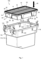
- Figure 1 depicts a filter system 100, in particular an air filter system 100, with a first housing part 112 and a filter element 10 according to an embodiment of the invention in an exploded view.
- the filter system 100 comprises a housing 110, where in Figure 1 only the first housing part 112, which is the lower part of the housing 110, is shown. Further the filter system 100 comprises the filter element 10 which in an intended use is accommodated in the housing 110.
- the filter element 10 comprises a filter body 12 with a filter medium 14, e.g. a pleated nonwoven, which is enclosed by a circumferential frame element 16.
- the frame element 16 supports a gasket 20 between the raw side and the clean side of the filter system 100.
- a receiving part 116 is provided on the first housing part 112 for receiving the filter element 10.
- the frame element 16 fits into a flange 128 of the receiving part 116 when the filter element 10 is mounted to the first housing part 112 so that the gasket 20 of the frame element 16 is received by a sealing surface of a second housing part 114 ( Figure 5 ) when closing the first housing part 112.
- a number of structure elements 24 are arranged on a circumference 50 of the filter element 10, e.g. in a side wall 18 of the circumference 50 and as part of the frame element 16, respectively.
- the receiving part 116 provides a number of corresponding counter elements 120 for cooperating with the structure elements 24.
- the counter elements 120 are arranged circumferentially on a wall 118 of the receiving part 116.
- the structure elements 24 and the counter elements 120 form a tight connection when the filter element 10 is arranged in the receiving part 116.
- the structure elements 24 are protruding from the circumference 50 of the filter element 10, whereas the counter elements 120 are configured as breakthroughs, e.g. slots, through the wall 118 of the receiving part 116. So the structure elements 24 fit into the counter elements 120 when the filter element 10 is mounted to the first housing part 112.
- the structure elements 24 are formed with a tapered shape 28 in a mounting direction 40. This facilitates mounting of the filter element 10 into the first housing part 112 as the structure elements 24 are self-centering in the counter elements 120 when the filter element 10 is moved in the mounting direction 40.
- the structure elements 24 are integral with the side walls 18 which at least partially surround the filter body 12. On a front side 34 the structure elements 24 are integral with the frame element 16 because the front side 34 is represented as the filter body 12 in this embodiment. In an alternative embodiment the side walls 18 may be realized on the whole circumference 50.
- the structure elements 24 could be breakthroughs through the side wall 18 arranged at the circumference 50 of the filter element 10, and the counter elements 120 could be protruding inward from the wall 118 of the receiving part 116.
- Such a configuration would also facilitate mounting of the filter element 10 to the first housing part 112 as the counter elements 10 would also fit into the structure elements 24.
- the gasket 20 is circumferentially arranged on a top side 30 of the frame element 16 and serves for sealing the raw fluid region inside the housing 110 of the filter system 100 against the filtered fluid region when the housing 110 is closed.
- the top region 22 of the filter body 12 directs to the filtered fluid region.
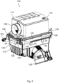
- Figure 2 depicts a detailed view of a structure element 24 of the filter element 10 according to Figure 1 .
- the structure elements 24 comprise grooves 26 in a circumference wall 32 for receiving edges of the counter elements 120 of the wall 118 of the receiving part 116 in a sealing manner, when the filter element 10 is being inserted into the receiving part 116.
- the housing 110 is sealed against the environment when the filter element 10 is inserted into the first housing part 112 and no harmful particles or fluid may enter the housing 110 when the filter element 10 is mounted.
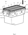
- Figure 3 depicts the filter element 10 according to Figure 1 during a mounting process into the first housing part 112, whereas in Figure 4 the filter element 10 is fully inserted into the first housing part 112.
- the filter element 10 is partly inserted into the first housing part 112.
- the slots of the counter elements 120 are not yet fully closed by the structure elements 10 of the filter element 10, whereas in Figure 4 the slots of the counter elements 120 are fully closed by the structure elements 10 of the filter element 10.
- the housing 110 is sealed against the environment.
- the housing 110 is also stiffened as the structure elements 24 of the filter element 10 also contribute to stiffening of the housing 110 by the close cooperation with the counter elements 120 of the first housing part 112.
- FIG. 5 a filter system 100 according to an embodiment of the invention is depicted with a filter element 10 inserted and the housing 100 closed.
- the housing 110 of the filter system 100 comprises the first housing part 112 and the second housing part 114.
- a fluid inlet 102 is formed in the first housing part 112
- a fluid outlet 108 is formed in the second housing part 114.
- the second housing part 114 is provided with a protruding edge 122 overlapping the first housing part 112 when mounted on top of the first housing part 112.
- snap hooks 124 two on each front side 130, are provided on the first housing part 112 for tightly closing the housing 110 by fitting into a corresponding groove 126 of the second housing part 114 when the housing 110 is in a closed state.
- one snap hook 124 is closed whereas the other snap hook 124 is open.
Landscapes
- Chemical & Material Sciences (AREA)
- Chemical Kinetics & Catalysis (AREA)
- Filtering Of Dispersed Particles In Gases (AREA)
Claims (5)
- Filtersystem (100), insbesondere en Luftfiltersystem (100), umfassend:ein Gehäuse (110), umfassend ein erstes Gehäuseteil (112) und ein zweites Gehäuseteil (114);einen in dem ersten Gehäuseteil (112) gebildeten Fluideinlass (102);einen in dem zweiten Gehäuseteil (114) gebildeten Fluidauslass (108); undein in dem Gehäuse (110) aufgenommenes Filterelement (10), und umfassend:einen Filterkörper (12) mit einem von einem umlaufenden Rahmenelement (16) umschlossenes Filtermedium (14); undvon einem Umfang (50) des Filterelements (10) vorstehende Strukturelemente (24), wobei die Strukturelemente (24) jeweils Rillen (26) in Umfangswänden (32) der Strukturelemente (24) umfassen,wobei der erste Gehäuseteil (112) einen Aufnahmeteil (116) zum Aufnehmen des Filterelements (10) umfasst, wobei der Aufnahmeteil (116) jeweils Gegenelemente (120) umfasst, die den Strukturelementen (24) entsprechen, und wobei die Gegenelemente (120) Durchbrüche sind, die in Umfangsrichtung an einer Wand (118) des Aufnahmeteils (116) angeordnet und durch diese hindurch geformt sind, undwobei die in den Strukturelementen (24) beinhalteten Rillen (26) dazu dienen, die Kanten der Durchbrüche der Gegenelemente (120) auf abdichtende Weise aufzunehmen, wenn das Filterelement (10) in dem Aufnahmeteil (116) angeordnet ist.
- Filtersystem nach Anspruch 1, wobei die Strukturelemente (24) mit einer konischen Form (28) in einer Montagerichtung (40) gebildet sind.
- Filtersystem nach einem der obigen Ansprüche, wobei der zweite Gehäuseteil (114) eine vorstehende Kante (122) umfasst, die den ersten Gehäuseteil (112) überlappt, wenn er auf dem ersten Gehäuseteil (112) installiert ist.
- Filtersystem nach einem der obigen Ansprüche, wobei das erste Gehäuseteil (112) ferner einen oder mehrere Schnapphaken (124) zum Schließen des Gehäuses (110) durch jeweiliges Einpassen in eine oder mehrere Rillen (126) umfasst, die in dem zweiten Gehäuseteil (114) enthalten sind.
- Filtersystem nach einem der obigen Ansprüche, wobei die Strukturelemente (24) mit einer Seitenwand (18), die den Filterkörper (12) mindestens teilweise umgibt, und/oder mit dem umlaufenden Rahmenelement (16) integral ausgebildet sind.
Priority Applications (4)
| Application Number | Priority Date | Filing Date | Title |
|---|---|---|---|
| EP22164761.3A EP4252887B1 (de) | 2022-03-28 | 2022-03-28 | Filtersystem und filterelement |
| US18/180,203 US20230321579A1 (en) | 2022-03-28 | 2023-03-08 | Filter System and Filter Element |
| KR1020230038475A KR20230139796A (ko) | 2022-03-28 | 2023-03-24 | 필터 시스템 및 필터 엘리먼트 |
| CN202310307935.3A CN116808742A (zh) | 2022-03-28 | 2023-03-27 | 过滤器系统和过滤器元件 |
Applications Claiming Priority (1)
| Application Number | Priority Date | Filing Date | Title |
|---|---|---|---|
| EP22164761.3A EP4252887B1 (de) | 2022-03-28 | 2022-03-28 | Filtersystem und filterelement |
Publications (2)
| Publication Number | Publication Date |
|---|---|
| EP4252887A1 EP4252887A1 (de) | 2023-10-04 |
| EP4252887B1 true EP4252887B1 (de) | 2025-03-12 |
Family
ID=80978951
Family Applications (1)
| Application Number | Title | Priority Date | Filing Date |
|---|---|---|---|
| EP22164761.3A Active EP4252887B1 (de) | 2022-03-28 | 2022-03-28 | Filtersystem und filterelement |
Country Status (4)
| Country | Link |
|---|---|
| US (1) | US20230321579A1 (de) |
| EP (1) | EP4252887B1 (de) |
| KR (1) | KR20230139796A (de) |
| CN (1) | CN116808742A (de) |
Families Citing this family (6)
| Publication number | Priority date | Publication date | Assignee | Title |
|---|---|---|---|---|
| US20230398480A1 (en) * | 2020-11-02 | 2023-12-14 | Cummins Filtration Inc. | Filter assemblies with alignment features |
| DE102024117371B3 (de) * | 2024-06-20 | 2025-08-28 | Daimler Truck AG | Gehäuseanordnung |
| USD1091992S1 (en) * | 2024-07-31 | 2025-09-02 | Beijing Roborock Technology Co., Ltd. | Dust filter for cleaning appliance |
| CA235887S (en) * | 2024-08-07 | 2025-09-25 | Beijing Roborock Technology Co Ltd | Dust box for cleaning robot |
| USD1097404S1 (en) * | 2024-08-08 | 2025-10-07 | Beijing Roborock Technology Co., Ltd. | Dust filter for cleaning appliance |
| CA233984S (en) * | 2024-09-03 | 2025-10-24 | Beijing Roborock Technology Co Ltd | Dust filter for cleaning appliance |
Family Cites Families (6)
| Publication number | Priority date | Publication date | Assignee | Title |
|---|---|---|---|---|
| DE102010053758A1 (de) * | 2010-12-08 | 2012-06-14 | Mann + Hummel Gmbh | Filterelement und Gehäuse zur Aufnahme des Filterelements |
| US9359982B2 (en) | 2011-01-11 | 2016-06-07 | Mann + Hummel Gmbh | Air cleaner assembly and filter element providing improved dynamic wall stiffness |
| DE102014009026A1 (de) * | 2013-07-12 | 2015-01-15 | Mann + Hummel Gmbh | Filterelement mit wenigstens einem Führungssteg, Filter mit einem Filterelement und Filtergehäuse eines Filters |
| DE102015015778A1 (de) * | 2015-01-12 | 2016-07-14 | Mann + Hummel Gmbh | Filterelement, Filter und Filtergehäuse eines Filters |
| DE102015007901A1 (de) * | 2015-06-22 | 2016-12-22 | Mann + Hummel Gmbh | Filterelement mit Vorabscheider und Filtersystem |
| DE102016006042A1 (de) * | 2016-05-18 | 2017-11-23 | Mann + Hummel Gmbh | Filteranordnung |
-
2022
- 2022-03-28 EP EP22164761.3A patent/EP4252887B1/de active Active
-
2023
- 2023-03-08 US US18/180,203 patent/US20230321579A1/en active Pending
- 2023-03-24 KR KR1020230038475A patent/KR20230139796A/ko active Pending
- 2023-03-27 CN CN202310307935.3A patent/CN116808742A/zh active Pending
Also Published As
| Publication number | Publication date |
|---|---|
| US20230321579A1 (en) | 2023-10-12 |
| EP4252887A1 (de) | 2023-10-04 |
| KR20230139796A (ko) | 2023-10-05 |
| CN116808742A (zh) | 2023-09-29 |
Similar Documents
| Publication | Publication Date | Title |
|---|---|---|
| EP4252887B1 (de) | Filtersystem und filterelement | |
| CN105964076B (zh) | 具有平衡密封的空气过滤器 | |
| US9359982B2 (en) | Air cleaner assembly and filter element providing improved dynamic wall stiffness | |
| CN105032000B (zh) | 不带有托板螺母的旋装过滤器 | |
| US8043504B2 (en) | Filter cartridge | |
| EP0518865B1 (de) | Hochleistungsluftfilter mit mehrzweckenddichtung | |
| EP2744584B1 (de) | Hydraulische spin-on-filterkartusche mit bodenplatte zur stützung einer radialabdichtung | |
| US9089805B2 (en) | Air filter and inlet tube assembly | |
| US20060091064A1 (en) | Filter apparatus with separable seal support frame | |
| EP3181210B1 (de) | Filteranordnung mit gehäuse für luftfilter und integriertem viereckigem dichtungsring | |
| CN115397537A (zh) | 封闭端帽形成以不同轴向距离定位的密封部的过滤元件 | |
| US20240091691A1 (en) | Filter Cartridge Including U-Shaped Canted Inlet Frame; Filter System Including Same | |
| CN110248714B (zh) | 适用于无螺纹外壳的可扩展螺纹适配器 | |
| EP3453443A1 (de) | Filtereinsatz, gitter für einen filtereinsatz und luftfiltersystem | |
| WO2020070682A1 (en) | Filter cartridge for a fuel filter group | |
| GB2070969A (en) | Air cleaner | |
| EP2522412A1 (de) | Filter mit Befestigungsvorrichtung | |
| EP4316627B1 (de) | Luftfilter mit verbessertem griff | |
| EP4221865B1 (de) | Filterelement | |
| CN215085596U (zh) | 滤芯支架 |
Legal Events
| Date | Code | Title | Description |
|---|---|---|---|
| PUAI | Public reference made under article 153(3) epc to a published international application that has entered the european phase |
Free format text: ORIGINAL CODE: 0009012 |
|
| STAA | Information on the status of an ep patent application or granted ep patent |
Free format text: STATUS: THE APPLICATION HAS BEEN PUBLISHED |
|
| AK | Designated contracting states |
Kind code of ref document: A1 Designated state(s): AL AT BE BG CH CY CZ DE DK EE ES FI FR GB GR HR HU IE IS IT LI LT LU LV MC MK MT NL NO PL PT RO RS SE SI SK SM TR |
|
| STAA | Information on the status of an ep patent application or granted ep patent |
Free format text: STATUS: REQUEST FOR EXAMINATION WAS MADE |
|
| 17P | Request for examination filed |
Effective date: 20240311 |
|
| RBV | Designated contracting states (corrected) |
Designated state(s): AL AT BE BG CH CY CZ DE DK EE ES FI FR GB GR HR HU IE IS IT LI LT LU LV MC MK MT NL NO PL PT RO RS SE SI SK SM TR |
|
| STAA | Information on the status of an ep patent application or granted ep patent |
Free format text: STATUS: EXAMINATION IS IN PROGRESS |
|
| 17Q | First examination report despatched |
Effective date: 20240528 |
|
| GRAP | Despatch of communication of intention to grant a patent |
Free format text: ORIGINAL CODE: EPIDOSNIGR1 |
|
| STAA | Information on the status of an ep patent application or granted ep patent |
Free format text: STATUS: GRANT OF PATENT IS INTENDED |
|
| INTG | Intention to grant announced |
Effective date: 20241010 |
|
| GRAS | Grant fee paid |
Free format text: ORIGINAL CODE: EPIDOSNIGR3 |
|
| GRAA | (expected) grant |
Free format text: ORIGINAL CODE: 0009210 |
|
| STAA | Information on the status of an ep patent application or granted ep patent |
Free format text: STATUS: THE PATENT HAS BEEN GRANTED |
|
| AK | Designated contracting states |
Kind code of ref document: B1 Designated state(s): AL AT BE BG CH CY CZ DE DK EE ES FI FR GB GR HR HU IE IS IT LI LT LU LV MC MK MT NL NO PL PT RO RS SE SI SK SM TR |
|
| REG | Reference to a national code |
Ref country code: GB Ref legal event code: FG4D |
|
| REG | Reference to a national code |
Ref country code: CH Ref legal event code: EP |
|
| REG | Reference to a national code |
Ref country code: DE Ref legal event code: R096 Ref document number: 602022011583 Country of ref document: DE |
|
| REG | Reference to a national code |
Ref country code: IE Ref legal event code: FG4D |
|
| PGFP | Annual fee paid to national office [announced via postgrant information from national office to epo] |
Ref country code: DE Payment date: 20250319 Year of fee payment: 4 |
|
| PGFP | Annual fee paid to national office [announced via postgrant information from national office to epo] |
Ref country code: AT Payment date: 20250417 Year of fee payment: 4 |
|
| PG25 | Lapsed in a contracting state [announced via postgrant information from national office to epo] |
Ref country code: RS Free format text: LAPSE BECAUSE OF FAILURE TO SUBMIT A TRANSLATION OF THE DESCRIPTION OR TO PAY THE FEE WITHIN THE PRESCRIBED TIME-LIMIT Effective date: 20250612 |
|
| PG25 | Lapsed in a contracting state [announced via postgrant information from national office to epo] |
Ref country code: FI Free format text: LAPSE BECAUSE OF FAILURE TO SUBMIT A TRANSLATION OF THE DESCRIPTION OR TO PAY THE FEE WITHIN THE PRESCRIBED TIME-LIMIT Effective date: 20250312 |
|
| PG25 | Lapsed in a contracting state [announced via postgrant information from national office to epo] |
Ref country code: ES Free format text: LAPSE BECAUSE OF FAILURE TO SUBMIT A TRANSLATION OF THE DESCRIPTION OR TO PAY THE FEE WITHIN THE PRESCRIBED TIME-LIMIT Effective date: 20250312 |
|
| REG | Reference to a national code |
Ref country code: LT Ref legal event code: MG9D |
|
| PG25 | Lapsed in a contracting state [announced via postgrant information from national office to epo] |
Ref country code: NO Free format text: LAPSE BECAUSE OF FAILURE TO SUBMIT A TRANSLATION OF THE DESCRIPTION OR TO PAY THE FEE WITHIN THE PRESCRIBED TIME-LIMIT Effective date: 20250612 |
|
| PG25 | Lapsed in a contracting state [announced via postgrant information from national office to epo] |
Ref country code: HR Free format text: LAPSE BECAUSE OF FAILURE TO SUBMIT A TRANSLATION OF THE DESCRIPTION OR TO PAY THE FEE WITHIN THE PRESCRIBED TIME-LIMIT Effective date: 20250312 |
|
| REG | Reference to a national code |
Ref country code: NL Ref legal event code: MP Effective date: 20250312 |
|
| PG25 | Lapsed in a contracting state [announced via postgrant information from national office to epo] |
Ref country code: LV Free format text: LAPSE BECAUSE OF FAILURE TO SUBMIT A TRANSLATION OF THE DESCRIPTION OR TO PAY THE FEE WITHIN THE PRESCRIBED TIME-LIMIT Effective date: 20250312 |
|
| PG25 | Lapsed in a contracting state [announced via postgrant information from national office to epo] |
Ref country code: GR Free format text: LAPSE BECAUSE OF FAILURE TO SUBMIT A TRANSLATION OF THE DESCRIPTION OR TO PAY THE FEE WITHIN THE PRESCRIBED TIME-LIMIT Effective date: 20250613 Ref country code: BG Free format text: LAPSE BECAUSE OF FAILURE TO SUBMIT A TRANSLATION OF THE DESCRIPTION OR TO PAY THE FEE WITHIN THE PRESCRIBED TIME-LIMIT Effective date: 20250312 |
|
| PG25 | Lapsed in a contracting state [announced via postgrant information from national office to epo] |
Ref country code: AT Free format text: LAPSE BECAUSE OF FAILURE TO SUBMIT A TRANSLATION OF THE DESCRIPTION OR TO PAY THE FEE WITHIN THE PRESCRIBED TIME-LIMIT Effective date: 20250312 |
|
| P01 | Opt-out of the competence of the unified patent court (upc) registered |
Free format text: CASE NUMBER: APP_31638/2025 Effective date: 20250701 |
|
| REG | Reference to a national code |
Ref country code: AT Ref legal event code: MK05 Ref document number: 1774560 Country of ref document: AT Kind code of ref document: T Effective date: 20250312 |
|
| PG25 | Lapsed in a contracting state [announced via postgrant information from national office to epo] |
Ref country code: NL Free format text: LAPSE BECAUSE OF FAILURE TO SUBMIT A TRANSLATION OF THE DESCRIPTION OR TO PAY THE FEE WITHIN THE PRESCRIBED TIME-LIMIT Effective date: 20250312 |
|
| PG25 | Lapsed in a contracting state [announced via postgrant information from national office to epo] |
Ref country code: SE Free format text: LAPSE BECAUSE OF FAILURE TO SUBMIT A TRANSLATION OF THE DESCRIPTION OR TO PAY THE FEE WITHIN THE PRESCRIBED TIME-LIMIT Effective date: 20250312 |
|
| PG25 | Lapsed in a contracting state [announced via postgrant information from national office to epo] |
Ref country code: SM Free format text: LAPSE BECAUSE OF FAILURE TO SUBMIT A TRANSLATION OF THE DESCRIPTION OR TO PAY THE FEE WITHIN THE PRESCRIBED TIME-LIMIT Effective date: 20250312 |
|
| PG25 | Lapsed in a contracting state [announced via postgrant information from national office to epo] |
Ref country code: PT Free format text: LAPSE BECAUSE OF FAILURE TO SUBMIT A TRANSLATION OF THE DESCRIPTION OR TO PAY THE FEE WITHIN THE PRESCRIBED TIME-LIMIT Effective date: 20250714 |
|
| PG25 | Lapsed in a contracting state [announced via postgrant information from national office to epo] |
Ref country code: PL Free format text: LAPSE BECAUSE OF FAILURE TO SUBMIT A TRANSLATION OF THE DESCRIPTION OR TO PAY THE FEE WITHIN THE PRESCRIBED TIME-LIMIT Effective date: 20250312 Ref country code: IT Free format text: LAPSE BECAUSE OF FAILURE TO SUBMIT A TRANSLATION OF THE DESCRIPTION OR TO PAY THE FEE WITHIN THE PRESCRIBED TIME-LIMIT Effective date: 20250312 |
|
| PG25 | Lapsed in a contracting state [announced via postgrant information from national office to epo] |
Ref country code: EE Free format text: LAPSE BECAUSE OF FAILURE TO SUBMIT A TRANSLATION OF THE DESCRIPTION OR TO PAY THE FEE WITHIN THE PRESCRIBED TIME-LIMIT Effective date: 20250312 Ref country code: CZ Free format text: LAPSE BECAUSE OF FAILURE TO SUBMIT A TRANSLATION OF THE DESCRIPTION OR TO PAY THE FEE WITHIN THE PRESCRIBED TIME-LIMIT Effective date: 20250312 |
|
| PG25 | Lapsed in a contracting state [announced via postgrant information from national office to epo] |
Ref country code: RO Free format text: LAPSE BECAUSE OF FAILURE TO SUBMIT A TRANSLATION OF THE DESCRIPTION OR TO PAY THE FEE WITHIN THE PRESCRIBED TIME-LIMIT Effective date: 20250312 |
|
| REG | Reference to a national code |
Ref country code: CH Ref legal event code: H13 Free format text: ST27 STATUS EVENT CODE: U-0-0-H10-H13 (AS PROVIDED BY THE NATIONAL OFFICE) Effective date: 20251024 |
|
| PG25 | Lapsed in a contracting state [announced via postgrant information from national office to epo] |
Ref country code: SK Free format text: LAPSE BECAUSE OF FAILURE TO SUBMIT A TRANSLATION OF THE DESCRIPTION OR TO PAY THE FEE WITHIN THE PRESCRIBED TIME-LIMIT Effective date: 20250312 |
|
| PG25 | Lapsed in a contracting state [announced via postgrant information from national office to epo] |
Ref country code: IS Free format text: LAPSE BECAUSE OF FAILURE TO SUBMIT A TRANSLATION OF THE DESCRIPTION OR TO PAY THE FEE WITHIN THE PRESCRIBED TIME-LIMIT Effective date: 20250712 |
|
| PG25 | Lapsed in a contracting state [announced via postgrant information from national office to epo] |
Ref country code: LU Free format text: LAPSE BECAUSE OF NON-PAYMENT OF DUE FEES Effective date: 20250328 |
|
| REG | Reference to a national code |
Ref country code: BE Ref legal event code: MM Effective date: 20250331 |
|
| REG | Reference to a national code |
Ref country code: DE Ref legal event code: R097 Ref document number: 602022011583 Country of ref document: DE |
|
| PG25 | Lapsed in a contracting state [announced via postgrant information from national office to epo] |
Ref country code: MC Free format text: LAPSE BECAUSE OF FAILURE TO SUBMIT A TRANSLATION OF THE DESCRIPTION OR TO PAY THE FEE WITHIN THE PRESCRIBED TIME-LIMIT Effective date: 20250312 |
|
| PG25 | Lapsed in a contracting state [announced via postgrant information from national office to epo] |
Ref country code: DK Free format text: LAPSE BECAUSE OF FAILURE TO SUBMIT A TRANSLATION OF THE DESCRIPTION OR TO PAY THE FEE WITHIN THE PRESCRIBED TIME-LIMIT Effective date: 20250312 |
|
| PG25 | Lapsed in a contracting state [announced via postgrant information from national office to epo] |
Ref country code: BE Free format text: LAPSE BECAUSE OF NON-PAYMENT OF DUE FEES Effective date: 20250331 |
|
| PLBE | No opposition filed within time limit |
Free format text: ORIGINAL CODE: 0009261 |
|
| STAA | Information on the status of an ep patent application or granted ep patent |
Free format text: STATUS: NO OPPOSITION FILED WITHIN TIME LIMIT |
|
| PG25 | Lapsed in a contracting state [announced via postgrant information from national office to epo] |
Ref country code: CH Free format text: LAPSE BECAUSE OF NON-PAYMENT OF DUE FEES Effective date: 20250331 |
|
| PG25 | Lapsed in a contracting state [announced via postgrant information from national office to epo] |
Ref country code: IE Free format text: LAPSE BECAUSE OF NON-PAYMENT OF DUE FEES Effective date: 20250328 |
|
| REG | Reference to a national code |
Ref country code: CH Ref legal event code: L10 Free format text: ST27 STATUS EVENT CODE: U-0-0-L10-L00 (AS PROVIDED BY THE NATIONAL OFFICE) Effective date: 20260121 |