EP4316627B1 - Luftfilter mit verbessertem griff - Google Patents
Luftfilter mit verbessertem griff Download PDFInfo
- Publication number
- EP4316627B1 EP4316627B1 EP23218333.5A EP23218333A EP4316627B1 EP 4316627 B1 EP4316627 B1 EP 4316627B1 EP 23218333 A EP23218333 A EP 23218333A EP 4316627 B1 EP4316627 B1 EP 4316627B1
- Authority
- EP
- European Patent Office
- Prior art keywords
- handle
- filter element
- frame
- media
- mass
- Prior art date
- Legal status (The legal status is an assumption and is not a legal conclusion. Google has not performed a legal analysis and makes no representation as to the accuracy of the status listed.)
- Active
Links
Images

Classifications
-
- B—PERFORMING OPERATIONS; TRANSPORTING
- B01—PHYSICAL OR CHEMICAL PROCESSES OR APPARATUS IN GENERAL
- B01D—SEPARATION
- B01D46/00—Filters or filtering processes specially modified for separating dispersed particles from gases or vapours
- B01D46/52—Particle separators, e.g. dust precipitators, using filters embodying folded corrugated or wound sheet material
- B01D46/521—Particle separators, e.g. dust precipitators, using filters embodying folded corrugated or wound sheet material using folded, pleated material
- B01D46/525—Particle separators, e.g. dust precipitators, using filters embodying folded corrugated or wound sheet material using folded, pleated material which comprises flutes
- B01D46/527—Particle separators, e.g. dust precipitators, using filters embodying folded corrugated or wound sheet material using folded, pleated material which comprises flutes in wound arrangement
-
- B—PERFORMING OPERATIONS; TRANSPORTING
- B01—PHYSICAL OR CHEMICAL PROCESSES OR APPARATUS IN GENERAL
- B01D—SEPARATION
- B01D46/00—Filters or filtering processes specially modified for separating dispersed particles from gases or vapours
- B01D46/0002—Casings; Housings; Frame constructions
- B01D46/0005—Mounting of filtering elements within casings, housings or frames
-
- B—PERFORMING OPERATIONS; TRANSPORTING
- B01—PHYSICAL OR CHEMICAL PROCESSES OR APPARATUS IN GENERAL
- B01D—SEPARATION
- B01D46/00—Filters or filtering processes specially modified for separating dispersed particles from gases or vapours
- B01D46/10—Particle separators, e.g. dust precipitators, using filter plates, sheets or pads having plane surfaces
- B01D46/12—Particle separators, e.g. dust precipitators, using filter plates, sheets or pads having plane surfaces in multiple arrangements
-
- B—PERFORMING OPERATIONS; TRANSPORTING
- B01—PHYSICAL OR CHEMICAL PROCESSES OR APPARATUS IN GENERAL
- B01D—SEPARATION
- B01D46/00—Filters or filtering processes specially modified for separating dispersed particles from gases or vapours
- B01D46/42—Auxiliary equipment or operation thereof
- B01D46/4227—Manipulating filters or filter elements, e.g. handles or extracting tools
-
- B—PERFORMING OPERATIONS; TRANSPORTING
- B01—PHYSICAL OR CHEMICAL PROCESSES OR APPARATUS IN GENERAL
- B01D—SEPARATION
- B01D46/00—Filters or filtering processes specially modified for separating dispersed particles from gases or vapours
- B01D46/52—Particle separators, e.g. dust precipitators, using filters embodying folded corrugated or wound sheet material
- B01D46/521—Particle separators, e.g. dust precipitators, using filters embodying folded corrugated or wound sheet material using folded, pleated material
-
- B—PERFORMING OPERATIONS; TRANSPORTING
- B01—PHYSICAL OR CHEMICAL PROCESSES OR APPARATUS IN GENERAL
- B01D—SEPARATION
- B01D2265/00—Casings, housings or mounting for filters specially adapted for separating dispersed particles from gases or vapours
- B01D2265/02—Non-permanent measures for connecting different parts of the filter
- B01D2265/028—Snap, latch or clip connecting means
-
- B—PERFORMING OPERATIONS; TRANSPORTING
- B01—PHYSICAL OR CHEMICAL PROCESSES OR APPARATUS IN GENERAL
- B01D—SEPARATION
- B01D2265/00—Casings, housings or mounting for filters specially adapted for separating dispersed particles from gases or vapours
- B01D2265/06—Details of supporting structures for filtering material, e.g. cores
-
- B—PERFORMING OPERATIONS; TRANSPORTING
- B01—PHYSICAL OR CHEMICAL PROCESSES OR APPARATUS IN GENERAL
- B01D—SEPARATION
- B01D2271/00—Sealings for filters specially adapted for separating dispersed particles from gases or vapours
- B01D2271/02—Gaskets, sealings
Definitions
- This invention generally relates to air filters, and more particularly to the handle structures of such air filters for manipulation and/or arrangement in an air cleaner.
- an air filter product utilizes a small, plastic projection that snaps into the center winding core for grasping to pull the filter out of sealing engagement with the housing, such as show in U.S. Patent Nos. 6,852,141 and 6,610,126 to Xu et al. , wherein the present embodiments herein may be for same air cleaner housing applications as replacements, such that dimensions, filter packs and housings disclosed therein are useable for the present embodiments.
- the grasping structure is small in relation to the size of the filter.
- the strength of the snap-fit attachment of the grasping projection may be less than necessary to lift or remove a filter (with or without retained contaminant). If the grasping projection breaks away, it cannot be repaired/replaced leading to significant customer dissatisfaction.
- the location and shape of the grasping projection is not considered 'user-friendly' by the customer.
- the air filter elements according to the various embodiments disclosed herein may be used as replacement filters in the air cleaner housings such as disclosed in 6,610,126 to Xu et al and/or 8,083,825 to Mosset et al.
- the handle structure may also engage the air cleaner housing according to the patent records, to help with filter positioning.
- the claimed invention provides a filter element with at least one handle structure configuration, as defined in appended claim 1.
- Optional features are defined in the appended dependent claims.
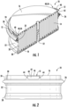
- the air filter element 10 includes a mass of media such as a filter media pack 14 comprising a suitable air filter media (e.g. typically non-woven fibrous media of cellulose and/or synthetic polymeric fibers in a sheet).
- the filter media pack 14 defines an inlet face 16, an outlet face 18 and an outer periphery 20 that is an annular side (e.g. cylindrical outer wall in the present example).
- the outer periphery 20 faces radially outward and extends axially between the inlet face 16 and the outlet face 18 to provide a filtered fluid flow path extending axially from the inlet face to the outlet face and through the air filter media for contaminant removal.
- This may be considered to be an axial flow type filter (also referenced as an inline filter, in that the air can pass through the faces generally along the same direction).
- the filter media pack 14 in this example is preferably a fluted filter media pack, which is known in the art to comprise a fluted sheet and a facing sheet that are secured together to define inlet flutes occluded a the outlet end and outlet flutes occluded at the inlet end so that unfiltered air must pass through one of the sheets of filter media to remove contaminants from the airflow.
- a suitable fluted filter media pack and method of manufacture useable for the media pack herein is shown for example in the aforementioned U.S. Patent No. 8,083,825 to Mosset et al. and/or US 7,255,300 to Johnston et al. entitled "Method and apparatus for winding a filter media pack,".
- an outer wrapper 22 such as provided in US 2019/0105593 and entitled “Surface Coated Filter Method” may be utilized.
- outer wrapper 22 may be an integrally formed outer layer such as by spray or roller coating of polyurea material, however adhesively attached preformed wrappers of plastic sheet and/or of porous material such as a spun-bounded sheet may be used.
- the air filter element 10 includes a frame 24 secured to the filter media pack 14 and in surrounding relation of the outer periphery 20.
- the filter media pack 14 can be secured to the frame 24 through an annular adhesive of polyurethane that attaches the frame 14 through the outer wrapper 22.
- the frame is preferably a rigid structure such as made from rigid plastic and preferably nylon reinforced with glass fibers.
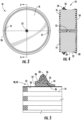
- the frame 24 can comprise an annular band 30 secured to the outer periphery 20 of the filter media pack via an adhesive 32.
- the annular band 30 extends axially but in radially spaced relation to the filter media pack 14 to define a potting well 34 therebetween, with the adhesive 32 being disposed in the potting well 34 for securement.
- the frame 24 may also include an annular shutoff lip 36 closing the potting well 34 at bottom of the annular band 30 while leaving an adequate fillable entrance region at the top for receipt of the adhesive, which is preferably a curable resin such as urethane that can also seal between the annular band and the filter media pack.
- the air filter element 10 includes a seal ring such as provided by a gasket 26 that is arranged in surrounding relation of the filter media pack 14. As illustrated, the gasket 26 may be supported by and mounted on the frame 24.
- the gasket 26 is considered a "dust seal" in that it serves to prevent dust penetrating along the side during use to help for cleaner change-out and/or as a back-up for a primary seal provided by radial seal gasket 28 secured proximate the outlet face 18.
- the dust seal type gasket 26 may be arranged proximate the inlet face 16 as illustrated.
- the gasket 26 is preferably an axial seal gasket but may alternatively be a radial seal like radial seal gasket 28, or as is the case in the embodiment of the claimed invention in FIGS. 6-10 .
- the frame 24 can include a seal support flange 38 extending radially outwardly from the annular band 30.
- the gasket 26 e.g. a dust seal
- the gasket 26 can be mounted around the seal support flange 38 to cover top bottom and outer sides thereof. As illustrated, the gasket 26 circumscribes a radially outward facing face of the annular band 30.
- handles 12 Secured to the frame 24 is a handle structure such as provided by the handles 12.
- the handles 12 can be secured to the frame integrally such as being unitarily molded therewith as single monolithic structure.
- each of the handles 12 can be grasped by the service mechanic to assist with installation and/or removal and are preferably sized large enough to receive two or more fingers of a mechanics hand therethrough, often typically with gloves upon the fingers.
- each of the handles 12 include handle aperture 42 having a horizontal length of between 5 and 20 centimeters and a vertical/axial width of between 2 and 10 centimeters to provide for manual grasping manipulation.
- the handles may be in the form of a closed loop strap with vertical legs 44 extending integral with the annular band 30 and a connecting bar 46 extending horizontally and connected tops of the vertical legs 44.
- the connecting bar 46 can provide for the handle top 40 that can be arranged in a preferred location relative to the inlet face.
- the handles 12 can also be arranged to provide for space savings and yet apply the force directly proximate to the periphery where the frame is located for reliable manipulation.
- the handles 12 are secured to the frame 24 proximate the outer periphery 20, with the handle structures extending to a region inside of an outer perimeter of the gasket 26, and the handles are primarily contained between the inlet face 16 and the outlet face 18 in that a majority of the axial span of the handle is disposed between inlet and outlet faces 16, 18.
- a top 40 of the handles 12 are generally flush with the inlet face.
- the handle top 40 can be positioned to provide stop structure to coact and/or abut with a corresponding air cleaner housing surface for proper positioning therein.
- the handle structures are interposed in an annular region 48 between the gasket 26 and the filter media pack 14 and extend axially along the outer periphery 20 generally parallel therewith (generally parallel being parallel or within 20 degrees of parallel), and with a radial air gap 50 providing a radial clearance region between the handle 12 and the pack 14 to allow a user to easily maneuver ones hand into the handle.
- the handle structures are preferably flush with or recessed below the inlet flow face 16.
- the handle structures need not interact with the winder core 52 used for winding a fluted type filter media pack 14, and force can be more directly applied to the seal support frame at the periphery rather than at a center region.
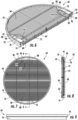
- a secondary air filter element 60 is illustrated, which may be usable in fluidic series with the primary air filter element 10 of the first embodiment.
- This second air filter element 60 also may incorporate an improved handle 62.
- the air filter element 60 also comprises a filter media pack 64 comprising an air filter media and having an inlet face 66, an outlet face 68 and an outer periphery 70.
- the outer periphery 70 extends between the inlet face 66 and the outlet face 68, to provide a filtered fluid flow path extending axially from the inlet face to the outlet face and through the air filter media for contaminant removal.
- the air filter media preferably is in the form of a pleated sheet 72 having folds with creased pleat tips at the inlet and outlet faces, but it is also an axial and inline direct flow filter arrangement like the first embodiment, just that the filter media sheet is configured and gathered differently.
- This type of filter pack is sometimes referred to as a pleated panel filter.
- This air filter element 60 includes a frame 74 secured to the outer periphery 70 of the filter media pack 64 and in surrounding relation of the outer periphery 70. Also, a gasket 76 is arranged in surrounding relation of the filter media pack 64 and that is preferably a radial seal gasket having an outer radial seal surface 78 that is compressible radially for radially sealing with a housing.
- the handles 62 are secured to the frame 74 proximate the outer periphery 70, with the handle structures similarly extending to a region inside of an outer perimeter of the gasket 76.
- the handles 62 structures lying substantially flat with the inlet face 66 across and over the inlet face 66.
- the handles 62 are pivotable structures secured integral with the frame 74, with the handles being sufficiently thin and flexible to provide an integral hinge 86.
- the frame 74 can comprise an annular band 80 sealingly secured to the outer periphery 70 of the of the filter media pack 64 such as with an annular application of adhesive 82 therebetween.
- the annular band 80 has an outer peripheral face 84 facing radially outward, with the gasket 76 circumscribing and mounted to the outer peripheral face 84.
- the frame further includes handle mount blocks 88 along an inner periphery of the annular band 80.
- the blocks 88 may define slits 90 that receive tabs 91 of the handles 62 with an integral arrangement such as via bonding or welding (e.g. sonic application or heat staking) to secure the handles in place.
- Such slits and tabs may also take the form of cylindrical pins and receiving holes.
- Each handle 62 can comprise a resilient handle loop 94 to provide a handle aperture 92.
- the loops 94 extend from a mounting base 96 (that includes insertion tab 91), with the base preferably integrally formed such as being welded to one of the mounting blocks 88.
- the loop 94 can provide a handle strap extending therefrom that lies substantially flat with the inlet face 66 when installed, thereby not occupying space, but is resilient pivotable from the mounting base via the flexibility allowed in the thinness of material at the hinges 86 to provide clearance to be grasped when pivoted.
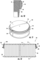
- FIGS. 11-16 illustrate a primary air filter element 110 with an alternative handle arrangement to that of the first example of FIGS. 1-5 .
- this third example is otherwise the same as the first example such that the same reference numbers are used for the same structures, and it is understood that the description for the first example is fully applicable to this example other than as indicated.
- the air filter element 110 of FIGS. 11-16 also includes the same fluted filter media pack 14 with inlet face 16, outlet face 18 and outer periphery 20, as well as the same axial seal gasket 26 and radial seal gasket 28.
- Optional outer wrapper 22 may also be employed.
- the frame 124 is mostly the same in that it also includes annular band 130 adhesively mounted in the same way such as via a urethane pour, however, the handle structures in this embodiment are in the form of handle mounts provided by vertically and axially projecting ears 112 that project from the annular band 130.
- the ears 112 pivotably support a bail handle 146 that is pivotably mounted to the pair support ears 112.
- the bail handle 146 is pivotable between an extended position providing a loop over the inlet face 16 for manual manipulation and a retracted position in which the bail handle is generally flush or below the inlet face 16, with the retracted position show in FIGS. 11 and 12 .
- An annular clearance region 148 is defined radially between the frame 124 and the filter media pack 14. As shown best in FIGS. 11 and 12 , the bail handle in the retracted position occupies the annular clearance region 148, and in particular the bail handle can be retracted to one side or the other side of the support ears 112 due to symmetry.
- a hinge structure 154 is provided and may be formed between ends of the bail handle 146 and the support ears 112.
- each of the ears 112 may have apertures 142 (which may include an insert slot 156 and a pivot aperture 158, with a snap project rib 157 therebetween), while the bail handle 146 may have pivot projections 159 including a neck portion 160 and a retainer head portion 162.
- the pivot projections 159 can be assembled due to the resiliently flexible nature of the bail handle 146 due to its length and thinness (which also may be a molded plastic member), with the head portions 162 insertable into the enlarged insert slot 156 and with the neck portions 160 then snapped and slid past the snap rib 157 to position the neck regions in the pivot aperture 158 and retained therein due to the enlarged head portion 162 being larger than the pivot aperture 142).
- the bail handle 146 comprises a pair of projections snap fit into respective apertures of the support ears.
Landscapes
- Chemical & Material Sciences (AREA)
- Chemical Kinetics & Catalysis (AREA)
- Filtering Of Dispersed Particles In Gases (AREA)
Claims (3)
- Ein Filterelement (60), das Folgendes umfasst: i) ein Massenmedium (64) mit einer Einlassfläche (66) an einem Ende und einer Auslassfläche (68) an einem anderen Ende und ii) eine Dichtringanordnung (74, 76), die das Massenmedium (64) des Filterelements entlang einer Außenoberfläche (70) davon im Umfang umgibt, wobei die Dichtringanordnung einen steifen Rahmen (74) umfasst, der an dem Massenmedium (64) des Filterelements fixiert ist und dieses stützt, und mindestens einen Griff (62), der mit einem ringförmigen Körperabschnitt des Rahmens (74) integral ist und von dem Körperabschnitt über eines der Enden des Massenmediums (64) des Filterelements frei vorsteht, wobei der mindestens eine Griff (62) lokalisiert und bemessen ist, um von einem Benutzer gegriffen zu werden, um das Filterelement (60) aus einem Gehäuse zu entfernen;wobei der steife Rahmen (74) ein ringförmiges Band (80) beinhaltet, das an dem Außenumfang (70) des Massenmediums des Filterelements gesichert ist, und das ringförmige Band (80) eine äußere Umfangsfläche (84) aufweist, die radial nach außen weist, wobei der Dichtring (76) die äußere Peripheriefläche (84) umschreibt und an dieser montiert ist und wobei das Massenmedium (64) eine gefaltete Filterplatte (72) beinhaltet;wobei auf entgegengesetzten Seiten der steife Rahmen (74) ferner mindestens einen Griffmontageblock (88) entlang eines Innenumfangs des ringförmigen Bands (80) umfasst, und wobei jeder Griff (62) einen elastischen Griff beinhaltet, der eine Montagebasis (96) integral integral zu einem des mindestens einen Montageblocks (88) und einen sich davon ausstreckenden Griffriemen (94) umfasst, der im Wesentlichen flach mit der Einlassfläche (66) liegt und von der Montagebasis (96), die gegriffen werden soll, elastisch schwenkbar ist.
- Filterelement (60) gemäß Anspruch 1, wobei sich der mindestens eine Griff (62) über die Einlassfläche (66) ausstreckt, wobei jeder elastische Griff (62) integral mit dem Rahmen (74) gesichert ist und wobei jeder schwenkbare Griffriemen (94) ausreichend dünn und flexibel ist, um ein integrales Scharnier (86) bereitzustellen.
- Filterelement (60) gemäß Anspruch 1, wobei der mindestens eine Griff (62) ein Paar Griffe (62) auf entgegengesetzten Seiten des Rahmens (74) beinhaltet.
Applications Claiming Priority (4)
| Application Number | Priority Date | Filing Date | Title |
|---|---|---|---|
| US201962815387P | 2019-03-08 | 2019-03-08 | |
| US201962851357P | 2019-05-22 | 2019-05-22 | |
| PCT/US2020/021161 WO2020185505A1 (en) | 2019-03-08 | 2020-03-05 | Air filter with improved handle |
| EP20770189.7A EP3934789B1 (de) | 2019-03-08 | 2020-03-05 | Luftfilter mit verbessertem griff |
Related Parent Applications (2)
| Application Number | Title | Priority Date | Filing Date |
|---|---|---|---|
| EP20770189.7A Division EP3934789B1 (de) | 2019-03-08 | 2020-03-05 | Luftfilter mit verbessertem griff |
| EP20770189.7A Division-Into EP3934789B1 (de) | 2019-03-08 | 2020-03-05 | Luftfilter mit verbessertem griff |
Publications (3)
| Publication Number | Publication Date |
|---|---|
| EP4316627A2 EP4316627A2 (de) | 2024-02-07 |
| EP4316627A3 EP4316627A3 (de) | 2024-02-28 |
| EP4316627B1 true EP4316627B1 (de) | 2025-05-07 |
Family
ID=72426453
Family Applications (2)
| Application Number | Title | Priority Date | Filing Date |
|---|---|---|---|
| EP23218333.5A Active EP4316627B1 (de) | 2019-03-08 | 2020-03-05 | Luftfilter mit verbessertem griff |
| EP20770189.7A Active EP3934789B1 (de) | 2019-03-08 | 2020-03-05 | Luftfilter mit verbessertem griff |
Family Applications After (1)
| Application Number | Title | Priority Date | Filing Date |
|---|---|---|---|
| EP20770189.7A Active EP3934789B1 (de) | 2019-03-08 | 2020-03-05 | Luftfilter mit verbessertem griff |
Country Status (4)
| Country | Link |
|---|---|
| US (1) | US12303817B2 (de) |
| EP (2) | EP4316627B1 (de) |
| BR (1) | BR112021016941A2 (de) |
| WO (1) | WO2020185505A1 (de) |
Family Cites Families (43)
| Publication number | Priority date | Publication date | Assignee | Title |
|---|---|---|---|---|
| US1002587A (en) | 1911-04-14 | 1911-09-05 | Karl Kiefer | Filter element. |
| US2771154A (en) * | 1952-09-12 | 1956-11-20 | American Air Filter Co | Filter frame handle construction |
| US2731155A (en) | 1953-03-27 | 1956-01-17 | Fram Corp | Filter cartridge pull-out device |
| US2739667A (en) | 1954-08-02 | 1956-03-27 | American Air Filter Co | Filter frame |
| US5556440A (en) * | 1994-10-20 | 1996-09-17 | Fleetguard, Inc. | Pressure-actuated radial air filter seal |
| GB2299769B (en) | 1995-04-11 | 1998-10-28 | Philips Electronics Uk Ltd | An air cleaner |
| US6235195B1 (en) | 1999-02-26 | 2001-05-22 | Donaldson Company, Inc. | Filter element incorporating a handle member |
| US6852141B2 (en) | 2001-06-06 | 2005-02-08 | Donaldson Company, Inc. | Filter element having center piece and methods |
| US6517598B2 (en) | 2001-06-06 | 2003-02-11 | Donaldson Company, Inc. | Filter element having flange and methods |
| US6610126B2 (en) | 2001-06-06 | 2003-08-26 | Donaldson Company, Inc. | Filter element having sealing members and methods |
| US6966940B2 (en) | 2002-04-04 | 2005-11-22 | Donaldson Company, Inc. | Air filter cartridge |
| EP1509311B2 (de) | 2002-05-09 | 2008-12-17 | Donaldson Company, Inc. | Luftfilter mit gefalteten filtermedien |
| GB2389323B (en) | 2002-06-07 | 2005-08-17 | Baldwin Filters Inc | Environmentally friendly filter cartridge |
| KR20050098922A (ko) | 2003-02-11 | 2005-10-12 | 도널드선 컴파니 인코포레이티드 | 에어 크리너 배열과 서비스가능한 필터 구성 요소 및 방법 |
| JP4528305B2 (ja) * | 2003-11-12 | 2010-08-18 | ドナルドソン カンパニー,インコーポレイティド | フィルタエレメント用のスライドマウントを有するエアフィルタ |
| JP4664969B2 (ja) | 2004-03-24 | 2011-04-06 | ドナルドソン カンパニー,インコーポレイティド | フィルタエレメント、エアクリーナ、組立体および濾過方法 |
| US7905936B2 (en) | 2004-04-30 | 2011-03-15 | Donaldson Company, Inc. | Filter arrangements; housing; assemblies; and, methods |
| EP1781397B1 (de) * | 2004-06-18 | 2013-06-12 | Donaldson Company, Inc. | Luftreinigungsvorrichtungsanordnungen und verfahren |
| EP1781398B1 (de) | 2004-07-20 | 2010-02-17 | Donaldson Company, Inc. | Z-filtermedienpackungsanordnung, filterpatrone, luftreinigungsvorrichtungsanordnung und verfahren |
| WO2006014941A2 (en) | 2004-07-26 | 2006-02-09 | Donaldson Company, Inc. | Z-filter media pack arrangement; and, methods |
| US7326342B2 (en) | 2004-09-13 | 2008-02-05 | Baldwin Filters, Inc. | Fuel filter cartridge and keyed end cap |
| US7318851B2 (en) | 2004-11-02 | 2008-01-15 | Baldwin Filters, Inc. | Filter element |
| US7931725B2 (en) | 2004-11-02 | 2011-04-26 | Baldwin Filters, Inc. | Fluted filter apparatus |
| US7261756B2 (en) | 2004-11-02 | 2007-08-28 | Baldwin Filters, Inc. | Safety filter element |
| US7255300B2 (en) | 2004-11-03 | 2007-08-14 | Baldwin Filters, Inc. | Method and apparatus for winding a filter media pack |
| WO2006093960A2 (en) | 2005-02-28 | 2006-09-08 | Donaldson Company, Inc. | Filter arrangement and methods |
| DE102005031058A1 (de) * | 2005-07-02 | 2007-01-04 | Mahle International Gmbh | Filterelement und ein zu dessen Aufnahme geeignetes Filtergehäuse |
| WO2007084689A2 (en) | 2006-01-20 | 2007-07-26 | Donaldson Company, Inc. | Air cleaner configured for receipt of various sized filter cartridges; components thereof; and, methods |
| US7625419B2 (en) | 2006-05-10 | 2009-12-01 | Donaldson Company, Inc. | Air filter arrangement; assembly; and, methods |
| GB2440515B (en) | 2006-08-01 | 2011-06-15 | Dyson Technology Ltd | A filter assembly |
| US8709248B2 (en) | 2007-07-11 | 2014-04-29 | Baldwin Filters, Inc. | Molded filter end cap and method of manufacture |
| SE531096C2 (sv) | 2007-08-27 | 2008-12-16 | Electrolux Ab | Löstagbar filterinsats för en dammsugare |
| EP2190554B1 (de) * | 2007-09-07 | 2013-01-09 | Donaldson Company, Inc. | Luftfilteranordnung |
| US9675225B2 (en) | 2008-07-04 | 2017-06-13 | Emerson Electric Co. | Filter cage for wet/dry vacuums |
| WO2010114906A1 (en) | 2009-03-31 | 2010-10-07 | Donaldson Company, Inc. | Air cleaner, components thereof, and methods |
| WO2011041129A1 (en) | 2009-10-02 | 2011-04-07 | Donaldson Company, Inc. | Filter cartridge with centerboard, dust collectors, and methods |
| JP6408570B2 (ja) | 2013-06-28 | 2018-10-17 | ドナルドソン カンパニー,インコーポレイティド | フィルタカートリッジ及びエアクリーナアセンブリ |
| JP6352076B2 (ja) | 2013-07-12 | 2018-07-04 | マン ウント フンメル ゲゼルシャフト ミット ベシュレンクテル ハフツング | ハンドグリップエレメントを有するフィルタエレメント及びフィルタエレメントを有するフィルタ |
| US10974188B2 (en) | 2015-07-15 | 2021-04-13 | Baldwin Filters, Inc. | Filter with shield features |
| DE102016001134A1 (de) * | 2016-02-03 | 2017-08-03 | Mann + Hummel Gmbh | Filtergehäuse und Filter |
| DE102016001132A1 (de) | 2016-02-03 | 2017-08-03 | Mann + Hummel Gmbh | Filterelement, Elementrahmen eines Filterelements, Filterbalg eines Filterelements, Filtergehäuse und Filter |
| EP3416734B1 (de) | 2016-02-19 | 2020-10-28 | Baldwin Filters, Inc. | Oberflächenbeschichtetes filter und verfahren |
| CN109715265B (zh) * | 2016-07-06 | 2021-11-19 | 唐纳森公司 | 空气滤清器组件 |
-
2020
- 2020-03-05 BR BR112021016941A patent/BR112021016941A2/pt unknown
- 2020-03-05 EP EP23218333.5A patent/EP4316627B1/de active Active
- 2020-03-05 EP EP20770189.7A patent/EP3934789B1/de active Active
- 2020-03-05 WO PCT/US2020/021161 patent/WO2020185505A1/en not_active Ceased
-
2021
- 2021-06-17 US US17/350,429 patent/US12303817B2/en active Active
Also Published As
| Publication number | Publication date |
|---|---|
| EP4316627A3 (de) | 2024-02-28 |
| US12303817B2 (en) | 2025-05-20 |
| WO2020185505A1 (en) | 2020-09-17 |
| BR112021016941A2 (pt) | 2021-11-03 |
| EP3934789B1 (de) | 2024-01-24 |
| EP4316627A2 (de) | 2024-02-07 |
| EP3934789A4 (de) | 2022-10-26 |
| US20210308613A1 (en) | 2021-10-07 |
| EP3934789A1 (de) | 2022-01-12 |
Similar Documents
| Publication | Publication Date | Title |
|---|---|---|
| US8673043B2 (en) | Fluid filter | |
| AU2005301259B2 (en) | Filter assembly with sealing system | |
| US7976601B2 (en) | Filter element having sealing members and methods | |
| EP2227306B1 (de) | Filtervorrichtung | |
| KR102253588B1 (ko) | 필터 카트리지, 조립체의 특징과 방법, 필터 조립체, 및 필터 카트리지 결합물 | |
| US7267706B2 (en) | Air filter | |
| EP3013455B1 (de) | Luftfilter und einlassrohranordnung | |
| EP1307272B1 (de) | Filteranordnung | |
| EP4252887B1 (de) | Filtersystem und filterelement | |
| AU2005301228B2 (en) | Safety filter element | |
| WO2006049702A1 (en) | Filter apparatus with separable seal support frame | |
| US20060090431A1 (en) | Filter assembly with combination filter element | |
| EP3585498B1 (de) | Filter mit abschirmungsmerkmalen | |
| EP4316627B1 (de) | Luftfilter mit verbessertem griff | |
| JP4831355B2 (ja) | エアクリーナ | |
| WO2011115979A2 (en) | Fluid filter | |
| EP4221865B1 (de) | Filterelement | |
| US11958007B2 (en) | Filter element | |
| BR122025001878A2 (pt) | Elemento de filtro |
Legal Events
| Date | Code | Title | Description |
|---|---|---|---|
| PUAI | Public reference made under article 153(3) epc to a published international application that has entered the european phase |
Free format text: ORIGINAL CODE: 0009012 |
|
| STAA | Information on the status of an ep patent application or granted ep patent |
Free format text: STATUS: THE APPLICATION HAS BEEN PUBLISHED |
|
| REG | Reference to a national code |
Ref country code: DE Free format text: PREVIOUS MAIN CLASS: B01D0046000000 Ref country code: DE Ref legal event code: R079 Ref document number: 602020051140 Country of ref document: DE Free format text: PREVIOUS MAIN CLASS: B01D0046000000 Ipc: B01D0046520000 |
|
| PUAL | Search report despatched |
Free format text: ORIGINAL CODE: 0009013 |
|
| AC | Divisional application: reference to earlier application |
Ref document number: 3934789 Country of ref document: EP Kind code of ref document: P |
|
| AK | Designated contracting states |
Kind code of ref document: A2 Designated state(s): AL AT BE BG CH CY CZ DE DK EE ES FI FR GB GR HR HU IE IS IT LI LT LU LV MC MK MT NL NO PL PT RO RS SE SI SK SM TR |
|
| AK | Designated contracting states |
Kind code of ref document: A3 Designated state(s): AL AT BE BG CH CY CZ DE DK EE ES FI FR GB GR HR HU IE IS IT LI LT LU LV MC MK MT NL NO PL PT RO RS SE SI SK SM TR |
|
| RIC1 | Information provided on ipc code assigned before grant |
Ipc: B01D 46/00 20220101ALI20240124BHEP Ipc: B01D 46/52 20060101AFI20240124BHEP |
|
| P01 | Opt-out of the competence of the unified patent court (upc) registered |
Effective date: 20240408 |
|
| STAA | Information on the status of an ep patent application or granted ep patent |
Free format text: STATUS: REQUEST FOR EXAMINATION WAS MADE |
|
| 17P | Request for examination filed |
Effective date: 20240807 |
|
| RBV | Designated contracting states (corrected) |
Designated state(s): AL AT BE BG CH CY CZ DE DK EE ES FI FR GB GR HR HU IE IS IT LI LT LU LV MC MK MT NL NO PL PT RO RS SE SI SK SM TR |
|
| GRAP | Despatch of communication of intention to grant a patent |
Free format text: ORIGINAL CODE: EPIDOSNIGR1 |
|
| STAA | Information on the status of an ep patent application or granted ep patent |
Free format text: STATUS: GRANT OF PATENT IS INTENDED |
|
| INTG | Intention to grant announced |
Effective date: 20241114 |
|
| GRAJ | Information related to disapproval of communication of intention to grant by the applicant or resumption of examination proceedings by the epo deleted |
Free format text: ORIGINAL CODE: EPIDOSDIGR1 |
|
| STAA | Information on the status of an ep patent application or granted ep patent |
Free format text: STATUS: REQUEST FOR EXAMINATION WAS MADE |
|
| GRAP | Despatch of communication of intention to grant a patent |
Free format text: ORIGINAL CODE: EPIDOSNIGR1 |
|
| STAA | Information on the status of an ep patent application or granted ep patent |
Free format text: STATUS: GRANT OF PATENT IS INTENDED |
|
| INTC | Intention to grant announced (deleted) | ||
| INTG | Intention to grant announced |
Effective date: 20250127 |
|
| GRAS | Grant fee paid |
Free format text: ORIGINAL CODE: EPIDOSNIGR3 |
|
| GRAA | (expected) grant |
Free format text: ORIGINAL CODE: 0009210 |
|
| STAA | Information on the status of an ep patent application or granted ep patent |
Free format text: STATUS: THE PATENT HAS BEEN GRANTED |
|
| AC | Divisional application: reference to earlier application |
Ref document number: 3934789 Country of ref document: EP Kind code of ref document: P |
|
| AK | Designated contracting states |
Kind code of ref document: B1 Designated state(s): AL AT BE BG CH CY CZ DE DK EE ES FI FR GB GR HR HU IE IS IT LI LT LU LV MC MK MT NL NO PL PT RO RS SE SI SK SM TR |
|
| REG | Reference to a national code |
Ref country code: GB Ref legal event code: FG4D |
|
| REG | Reference to a national code |
Ref country code: CH Ref legal event code: EP |
|
| REG | Reference to a national code |
Ref country code: DE Ref legal event code: R096 Ref document number: 602020051140 Country of ref document: DE |
|
| REG | Reference to a national code |
Ref country code: IE Ref legal event code: FG4D |
|
| REG | Reference to a national code |
Ref country code: NL Ref legal event code: MP Effective date: 20250507 |
|
| PG25 | Lapsed in a contracting state [announced via postgrant information from national office to epo] |
Ref country code: PT Free format text: LAPSE BECAUSE OF FAILURE TO SUBMIT A TRANSLATION OF THE DESCRIPTION OR TO PAY THE FEE WITHIN THE PRESCRIBED TIME-LIMIT Effective date: 20250908 Ref country code: ES Free format text: LAPSE BECAUSE OF FAILURE TO SUBMIT A TRANSLATION OF THE DESCRIPTION OR TO PAY THE FEE WITHIN THE PRESCRIBED TIME-LIMIT Effective date: 20250507 Ref country code: FI Free format text: LAPSE BECAUSE OF FAILURE TO SUBMIT A TRANSLATION OF THE DESCRIPTION OR TO PAY THE FEE WITHIN THE PRESCRIBED TIME-LIMIT Effective date: 20250507 |
|
| REG | Reference to a national code |
Ref country code: LT Ref legal event code: MG9D |
|
| PG25 | Lapsed in a contracting state [announced via postgrant information from national office to epo] |
Ref country code: NO Free format text: LAPSE BECAUSE OF FAILURE TO SUBMIT A TRANSLATION OF THE DESCRIPTION OR TO PAY THE FEE WITHIN THE PRESCRIBED TIME-LIMIT Effective date: 20250807 Ref country code: GR Free format text: LAPSE BECAUSE OF FAILURE TO SUBMIT A TRANSLATION OF THE DESCRIPTION OR TO PAY THE FEE WITHIN THE PRESCRIBED TIME-LIMIT Effective date: 20250808 |
|
| PG25 | Lapsed in a contracting state [announced via postgrant information from national office to epo] |
Ref country code: NL Free format text: LAPSE BECAUSE OF FAILURE TO SUBMIT A TRANSLATION OF THE DESCRIPTION OR TO PAY THE FEE WITHIN THE PRESCRIBED TIME-LIMIT Effective date: 20250507 Ref country code: PL Free format text: LAPSE BECAUSE OF FAILURE TO SUBMIT A TRANSLATION OF THE DESCRIPTION OR TO PAY THE FEE WITHIN THE PRESCRIBED TIME-LIMIT Effective date: 20250507 |
|
| REG | Reference to a national code |
Ref country code: AT Ref legal event code: MK05 Ref document number: 1791886 Country of ref document: AT Kind code of ref document: T Effective date: 20250507 |
|
| PG25 | Lapsed in a contracting state [announced via postgrant information from national office to epo] |
Ref country code: BG Free format text: LAPSE BECAUSE OF FAILURE TO SUBMIT A TRANSLATION OF THE DESCRIPTION OR TO PAY THE FEE WITHIN THE PRESCRIBED TIME-LIMIT Effective date: 20250507 |
|
| PG25 | Lapsed in a contracting state [announced via postgrant information from national office to epo] |
Ref country code: HR Free format text: LAPSE BECAUSE OF FAILURE TO SUBMIT A TRANSLATION OF THE DESCRIPTION OR TO PAY THE FEE WITHIN THE PRESCRIBED TIME-LIMIT Effective date: 20250507 |
|
| PG25 | Lapsed in a contracting state [announced via postgrant information from national office to epo] |
Ref country code: AT Free format text: LAPSE BECAUSE OF FAILURE TO SUBMIT A TRANSLATION OF THE DESCRIPTION OR TO PAY THE FEE WITHIN THE PRESCRIBED TIME-LIMIT Effective date: 20250507 |
|
| PG25 | Lapsed in a contracting state [announced via postgrant information from national office to epo] |
Ref country code: RS Free format text: LAPSE BECAUSE OF FAILURE TO SUBMIT A TRANSLATION OF THE DESCRIPTION OR TO PAY THE FEE WITHIN THE PRESCRIBED TIME-LIMIT Effective date: 20250807 |
|
| PG25 | Lapsed in a contracting state [announced via postgrant information from national office to epo] |
Ref country code: IS Free format text: LAPSE BECAUSE OF FAILURE TO SUBMIT A TRANSLATION OF THE DESCRIPTION OR TO PAY THE FEE WITHIN THE PRESCRIBED TIME-LIMIT Effective date: 20250907 |
|
| PG25 | Lapsed in a contracting state [announced via postgrant information from national office to epo] |
Ref country code: LV Free format text: LAPSE BECAUSE OF FAILURE TO SUBMIT A TRANSLATION OF THE DESCRIPTION OR TO PAY THE FEE WITHIN THE PRESCRIBED TIME-LIMIT Effective date: 20250507 |
|
| PG25 | Lapsed in a contracting state [announced via postgrant information from national office to epo] |
Ref country code: SM Free format text: LAPSE BECAUSE OF FAILURE TO SUBMIT A TRANSLATION OF THE DESCRIPTION OR TO PAY THE FEE WITHIN THE PRESCRIBED TIME-LIMIT Effective date: 20250507 Ref country code: DK Free format text: LAPSE BECAUSE OF FAILURE TO SUBMIT A TRANSLATION OF THE DESCRIPTION OR TO PAY THE FEE WITHIN THE PRESCRIBED TIME-LIMIT Effective date: 20250507 |
|
| PG25 | Lapsed in a contracting state [announced via postgrant information from national office to epo] |
Ref country code: CZ Free format text: LAPSE BECAUSE OF FAILURE TO SUBMIT A TRANSLATION OF THE DESCRIPTION OR TO PAY THE FEE WITHIN THE PRESCRIBED TIME-LIMIT Effective date: 20250507 |
|
| PG25 | Lapsed in a contracting state [announced via postgrant information from national office to epo] |
Ref country code: EE Free format text: LAPSE BECAUSE OF FAILURE TO SUBMIT A TRANSLATION OF THE DESCRIPTION OR TO PAY THE FEE WITHIN THE PRESCRIBED TIME-LIMIT Effective date: 20250507 |
|
| PG25 | Lapsed in a contracting state [announced via postgrant information from national office to epo] |
Ref country code: SK Free format text: LAPSE BECAUSE OF FAILURE TO SUBMIT A TRANSLATION OF THE DESCRIPTION OR TO PAY THE FEE WITHIN THE PRESCRIBED TIME-LIMIT Effective date: 20250507 |
|
| PG25 | Lapsed in a contracting state [announced via postgrant information from national office to epo] |
Ref country code: IT Free format text: LAPSE BECAUSE OF FAILURE TO SUBMIT A TRANSLATION OF THE DESCRIPTION OR TO PAY THE FEE WITHIN THE PRESCRIBED TIME-LIMIT Effective date: 20250507 |