EP4252601B1 - Elektrische mühle - Google Patents
Elektrische mühle Download PDFInfo
- Publication number
- EP4252601B1 EP4252601B1 EP22174763.7A EP22174763A EP4252601B1 EP 4252601 B1 EP4252601 B1 EP 4252601B1 EP 22174763 A EP22174763 A EP 22174763A EP 4252601 B1 EP4252601 B1 EP 4252601B1
- Authority
- EP
- European Patent Office
- Prior art keywords
- dust cover
- shell
- cover
- opening
- electric grinder
- Prior art date
- Legal status (The legal status is an assumption and is not a legal conclusion. Google has not performed a legal analysis and makes no representation as to the accuracy of the status listed.)
- Active
Links
Images


Classifications
-
- A—HUMAN NECESSITIES
- A47—FURNITURE; DOMESTIC ARTICLES OR APPLIANCES; COFFEE MILLS; SPICE MILLS; SUCTION CLEANERS IN GENERAL
- A47J—KITCHEN EQUIPMENT; COFFEE MILLS; SPICE MILLS; APPARATUS FOR MAKING BEVERAGES
- A47J42/00—Coffee mills; Spice mills
- A47J42/38—Parts or details
- A47J42/40—Parts or details relating to discharge, receiving container or the like; Bag clamps, e.g. with means for actuating electric switches
-
- A—HUMAN NECESSITIES
- A47—FURNITURE; DOMESTIC ARTICLES OR APPLIANCES; COFFEE MILLS; SPICE MILLS; SUCTION CLEANERS IN GENERAL
- A47J—KITCHEN EQUIPMENT; COFFEE MILLS; SPICE MILLS; APPARATUS FOR MAKING BEVERAGES
- A47J42/00—Coffee mills; Spice mills
-
- A—HUMAN NECESSITIES
- A47—FURNITURE; DOMESTIC ARTICLES OR APPLIANCES; COFFEE MILLS; SPICE MILLS; SUCTION CLEANERS IN GENERAL
- A47J—KITCHEN EQUIPMENT; COFFEE MILLS; SPICE MILLS; APPARATUS FOR MAKING BEVERAGES
- A47J42/00—Coffee mills; Spice mills
- A47J42/38—Parts or details
- A47J42/46—Driving mechanisms; Coupling to drives
-
- A—HUMAN NECESSITIES
- A47—FURNITURE; DOMESTIC ARTICLES OR APPLIANCES; COFFEE MILLS; SPICE MILLS; SUCTION CLEANERS IN GENERAL
- A47J—KITCHEN EQUIPMENT; COFFEE MILLS; SPICE MILLS; APPARATUS FOR MAKING BEVERAGES
- A47J42/00—Coffee mills; Spice mills
- A47J42/38—Parts or details
- A47J42/56—Safety devices
Definitions
- the present patent relates to the technical field of daily life utensils, especially an electric grinder.
- processed ground pepper, pepper salt, etc. available on the market differ greatly from freshly ground seasonings in flavor, more and more consumers choose pepper grinders. By buying complete pepper particles and grinding them in a grinder, they can get natural and fresh ground pepper, pepper salt, etc.
- Grinders currently available include both manual and electric grinders, and consumers can choose grinders suited to them based on actual needs.
- the Chinese patent application (publication number: CN209186447U) published on August 2, 2019 discloses a powder grinder, comprising a bottle, wherein a grinding device is provided at the mouth of said bottle, said grinding device comprises a rotatable rotating part engaged at the opening of said bottle, an inner core and an outer core that match each other are provided in said rotating part, grinding structures that match each other are provided on the outer wall of said inner core and the inner wall of said outer core, said inner core is supported by the inner core fixture in the opening of said bottle, said outer core is supported by the outer core fixture above the inner core fixture, an adjusting part that engages with it is provided on the top of said rotating part, and a dust cover is provided on the top of said adjusting part.
- the powder grinder of the present application adopts a worm and gear structure formed by an adjusting part and a rotating part, and has to rotate by 60° only to realize adjustment
- an electric grinder is more rational in structure and easier to operate, its dust cover is fastened on the top of the adjusting part.
- the pepper or ground pepper stored in the grinder will certainly be exposed to outside air for a long time, so that the flavor of the ground pepper will worsen, leading to a waste.
- the grinder is usually placed with the opening facing up. When the user forgets to fasten the dust cover, dust and other contaminants will enter the feed opening for grinding particles, so that the seasoning will be contaminated.
- US 2 223 260 A discloses a coffee mill comprising a discharge chamber with a pivoted gate, which is urged by gravity to a close position that serves to maintain ground coffee within the chamber.
- a pivoted gate which is urged by gravity to a close position that serves to maintain ground coffee within the chamber.
- An electric grinder comprising a shell, a motor assembly, a grinding assembly and a duct cover, wherein said motor assembly and said grinding assembly are provided in said shell, an opening is provided at one end of said shell, said dust cover is rotatably connected to said shell, said dust cover comprises a cover and a counterweight part, and said dust cover can open or close the opening of said shell under the gravity of said counterweight part.
- the present application sets a dust cover at the opening of the shell, and the dust cover can open or close the opening of the shell, thereby preventing dust from entering the feed opening effectively.
- the dust cover comprises a cover and a counterweight part, and said dust cover can open or close the opening of said shell under the gravity of said counterweight part.
- the electric grinder provided in the present embodiment comprise a shell 1, a motor assembly 2 and a grinding assembly 3, wherein said motor assembly 2 and said grinding assembly 3 are provided in said shell 1.
- the motor assembly 2 drives the grinding assembly 3 to realize the automatic grinding function of the electric grinder.
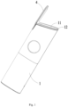
- the electric grinder of the present embodiment also comprises a dust cover 4, wherein an opening 11 is provided at one end of said shell 1, said dust cover 4 is rotatably connected to said shell 1, said dust cover 4 comprises a cover 41 and a counterweight part 42, and said dust cover 4 can open or close the opening 11 of said shell 1 under the gravity of said counterweight part 42.
- the present embodiment sets a counterweight part 42 at the tail of the dust cover 4, so that when the electric grinder is used, i.e., when the opening 11 of the electric grinder faces downward, the counterweight part 42 moves downward by gravity and drives the dust cover 4 away from the opening 11 of the shell 1, and when the opening 11 of the grinder faces upward, the counterweight part 42 returns to the starting position by gravity and drives the dust block to the starting position, so that the electric grinder is closed.
- said counterweight part 42 comprises a cavity 421 and a counterweight block 422, wherein said counterweight block 422 is located in said cavity 421.
- said cover 41 and said counterweight part 42 are molded integrally. Except this connection mode, the counterweight block 422 can also be otherwise connected to the cover 41 of the dust cover 4, such as gluing, riveting, and embedding and integral molding. Different connection modes play the same role, and no restriction is made here.
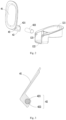
- said discharge cover 12 comprises a discharge part 121 and a containing part 122, wherein the lower part of said discharge part 121 can be inserted into the opening 11 of said shell 1, one end of said dust cover 4 is rotatably connected to said containing part 122, and said dust cover 4 can open or close the opening 11 of said shell 1.
- the present application sets a dust cover 4 at the opening 11 of the shell 1, and the dust cover 4 can open or close the opening 11 of the shell 1, thereby preventing dust from entering the feed opening 11 effectively.
- one end of the dust cover 4 is rotatably connected to containing part 122. When the opening 11 of the grinder faces up, rotating the dust cover 4 can close and press against the opening 11 of the dust cover 4 automatically, thereby preventing the feed opening 11 of the electric grinder from being exposed to air when the user forgets to close the dust cover 4.
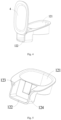
- a rotating shaft 43 is provided on said dust cover 4
- a shaft hole 123 is provided on said containing part 122, and said rotating shaft 43 and said shaft hole 123 match each other so that said dust cover 4 is rotatably connected to said discharge cover 12.
- Fig. 5 is a structural diagram of the discharge cover 12 in the present application
- Fig. 6 is a structural diagram of the dust cover 4 in the present application
- a groove 124 is provided on the outer wall of said containing part 122
- a convex rib 44 is provided at the tail of said dust cover 4.
- FIG. 8 which is an enlarged partial view of the electric grinder in the open state in the present application
- A is the external force that pushes the dust cover 4 away from the opening 11 of said shell 1
- B is the external force that pushes dust cover 4 toward the opening 11 of said shell 1.
- the convex rib 44 at the tail of the dust cover 4 will fall into the groove 124, even if the opening 11 of the electric grinder faces upward, the dust cover 4 will not reset due to the gravity of the counterweight block 422, and when the dust cover 4 is pushed by external force B toward the opening 11, the dust cover 4 will reset.
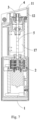
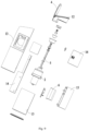
- Fig. 9 is an overall exploded view of the electric grinder in the present application.
- said shell 1 also comprises an enclosure 13, an inner front shell 14, an inner rear shell 15 and a storage bin cover 16, wherein said enclosure 13, inner front shell 14, inner rear shell 15 and storage bin cover 16 form the storage bin 17 of the electric grinder; a battery pack 6 and a motor assembly 2 are provided under said storage bin 17, a driving shaft 5 is provided in said storage bin 17, one end of said driving shaft 5 is connected to said motor assembly 2, and the other end of said driving shaft 5 is connected to said grinding assembly 3, wherein the cross section of said driving shaft 5 is non-circular.
- the electric grinder provided by the present embodiment can realize the automatic grinding of raw seasoning particles, such as pepper and sea salt particles.
- the dust cover 4 can open automatically, and when the opening 11 of the electric grinder faces upward, the dust cover 4 can close automatically.
- the dust cover 4 can be pushed away from the opening 11 of the shell 1, so that the electric grinder is open, making it convenient to be used by consumers.
Landscapes
- Engineering & Computer Science (AREA)
- Mechanical Engineering (AREA)
- Food Science & Technology (AREA)
- Grinding-Machine Dressing And Accessory Apparatuses (AREA)
Claims (8)
- Eine elektrische Mühle, umfassend ein Gehäuse (1), eine Motoreinheit (2), eine Mahleinheit (3) und eine Staubabdeckung (4), wobei die Motoreinheit (2) und die Mahleinheit (3) im Gehäuse (1) angeordnet sind, eine Öffnung (11) an einem Ende des Gehäuses (1) vorgesehen ist, die Staubabdeckung (4) drehbar mit dem Gehäuse (1) verbunden ist, die Staubabdeckung (4) eine Abdeckung (41) und ein Gegengewichtsteil (42) umfasst und die Staubabdeckung (4) die Öffnung (11) des Gehäuses (1) durch das Gewicht des Gegengewichtsteils (42) öffnen oder schließen kann, wobei die Staubabdeckung (4) die Öffnung (11) automatisch schließen und mit dieser in Kontakt treten kann, wenn die Öffnung (11) nach oben zeigt,
dadurch gekennzeichnet, dass das Gegengewichtsteil (42) eine Kavität (421) und einen Gegengewichtsblock (422) umfasst, wobei der Gegengewichtsblock (422) sich in der Kavität (421) befindet. - Eine elektrische Mühle nach Anspruch 1, wobei die Abdeckung (41) und das Gegengewichtsteil (42) einstückig geformt sind.
- Eine elektrische Mühle nach Anspruch 1 oder 2, wobei das Gehäuse (1) eine Auslassabdeckung (12) umfasst, die Auslassabdeckung (12) sich am Rand der Öffnung (11) des Gehäuses (1) befindet, die Auslassabdeckung (12) einen Auslassbereich (121) und einen Aufnahmeteils (122) umfasst, der untere Teil des Auslassbereichs (121) in die Öffnung (11) des Gehäuses (1) eingeführt werden kann, und ein Ende der Staubabdeckung (4) drehbar mit dem Aufnahmeteil (122) verbunden ist.
- Eine elektrische Mühle nach Anspruch 3, wobei eine Drehachse (43) an der Staubabdeckung (4) vorgesehen ist, ein Achsloch (123) am Aufnahmeteil (122) vorgesehen ist und die Drehachse (43) und das Achsloch (123) so zueinander passen, dass die Staubabdeckung (4) drehbar mit der Auslassabdeckung (12) verbunden ist.
- Eine elektrische Mühle nach Anspruch 3 oder 4, wobei eine Nut (124) an der Außenwand des Aufnahmeteils (122) vorgesehen ist und eine konvexe Rippe (44) am Ende der Staubabdeckung (4) vorhanden ist, wobei die konvexe Rippe (44) am Ende der Staubabdeckung (4) außerhalb der Nut (124) befindet, wenn die Staubabdeckung (4) geschlossen ist, und in die Nut (124) fällt, wenn die Staubabdeckung (4) von der Öffnung (11) des Gehäuses (1) weggedrückt wird.
- Eine elektrische Mühle nach einem der Ansprüche 1 bis 5, wobei das Gehäuse (1) außerdem eine Umhüllung (13), eine innere Frontschale (14), eine innere Rückschale (15) und eine Abdeckung des Lagerbehälters (16) umfasst, wobei die Umhüllung (13), die innere Frontschale (14), die innere Rückschale (15) und die Abdeckung des Lagerbehälters (16) den Lagerbehälter (17) der elektrischen Mühle bilden.
- Eine elektrische Mühle nach Anspruch 6, wobei die Motoreinheit (2) sich unter dem Lagerbehälter (17) befindet, eine Antriebswelle (5) im Lagerbehälter (17) vorgesehen ist, ein Ende der Antriebswelle (5) mit der Motoreinheit (2) verbunden ist und das andere Ende der Antriebswelle (5) mit der Mahleinheit (3) verbunden ist.
- Eine elektrische Mühle nach Anspruch 6 oder 7, wobei sich unter dem Lagerbehälter (17) außerdem ein Akkupack (6) befindet.
Applications Claiming Priority (1)
| Application Number | Priority Date | Filing Date | Title |
|---|---|---|---|
| CN202220673748.8U CN217659419U (zh) | 2022-04-01 | 2022-04-01 | 一种电动研磨器 |
Publications (3)
| Publication Number | Publication Date |
|---|---|
| EP4252601A1 EP4252601A1 (de) | 2023-10-04 |
| EP4252601C0 EP4252601C0 (de) | 2025-01-29 |
| EP4252601B1 true EP4252601B1 (de) | 2025-01-29 |
Family
ID=81842041
Family Applications (1)
| Application Number | Title | Priority Date | Filing Date |
|---|---|---|---|
| EP22174763.7A Active EP4252601B1 (de) | 2022-04-01 | 2022-05-23 | Elektrische mühle |
Country Status (3)
| Country | Link |
|---|---|
| US (1) | US11910959B2 (de) |
| EP (1) | EP4252601B1 (de) |
| CN (1) | CN217659419U (de) |
Families Citing this family (2)
| Publication number | Priority date | Publication date | Assignee | Title |
|---|---|---|---|---|
| CN217772110U (zh) | 2022-05-31 | 2022-11-11 | 珠海市启尔科技有限公司 | 一种电动研磨器 |
| USD1063498S1 (en) * | 2022-07-15 | 2025-02-25 | Zhuhai Kelitong Electronic Co., Ltd. | Electric grinder |
Family Cites Families (12)
| Publication number | Priority date | Publication date | Assignee | Title |
|---|---|---|---|---|
| US813649A (en) * | 1905-08-30 | 1906-02-27 | Dora Jones | Condiment-holder. |
| US1143656A (en) * | 1914-08-15 | 1915-06-22 | Otto Spahr | Bottle-closure. |
| US2223260A (en) * | 1937-07-02 | 1940-11-26 | Hobart Mfg Co | Coffee mill |
| DE8610515U1 (de) * | 1986-04-17 | 1986-06-26 | Rowenta-Werke Gmbh, 6050 Offenbach | Flüssigkeitsbehälter |
| US6443378B1 (en) * | 2001-03-20 | 2002-09-03 | James Huang | Pepper mill |
| US6511006B1 (en) * | 2001-07-16 | 2003-01-28 | Chef'n Corporation | Condiment grinder residue catch |
| US20040211848A1 (en) * | 2003-04-25 | 2004-10-28 | Conair Corporation | Coffee grinder with removable bin |
| FR2892288B1 (fr) * | 2005-10-20 | 2008-01-18 | Santos Soc Par Actions Simplif | Moulin a cafe comprenant des moyens de detection du niveau de cafe broye |
| US7762488B2 (en) * | 2008-10-30 | 2010-07-27 | Yienn Lih Enterprise Co., Ltd. | Electric pepper can |
| CN201775519U (zh) * | 2010-08-19 | 2011-03-30 | 张国平 | 一种电动研磨器 |
| CN209186447U (zh) | 2018-07-13 | 2019-08-02 | 南京雁客食品有限公司 | 一种粉料研磨器 |
| CN212015352U (zh) * | 2019-12-07 | 2020-11-27 | 上海麦睿斯国际贸易有限公司 | 便携式可加料研磨器 |
-
2022
- 2022-04-01 CN CN202220673748.8U patent/CN217659419U/zh active Active
- 2022-05-16 US US17/745,381 patent/US11910959B2/en active Active
- 2022-05-23 EP EP22174763.7A patent/EP4252601B1/de active Active
Also Published As
| Publication number | Publication date |
|---|---|
| EP4252601C0 (de) | 2025-01-29 |
| US20230301462A1 (en) | 2023-09-28 |
| US11910959B2 (en) | 2024-02-27 |
| CN217659419U (zh) | 2022-10-28 |
| EP4252601A1 (de) | 2023-10-04 |
Similar Documents
| Publication | Publication Date | Title |
|---|---|---|
| EP4252601B1 (de) | Elektrische mühle | |
| US7604191B2 (en) | Grinder | |
| US7793874B2 (en) | Grinder and automatic open/close control device thereof | |
| EP1964498B1 (de) | Mühle | |
| EP2606790B1 (de) | Elektrische schleifmaschine | |
| KR102489264B1 (ko) | 믹서기 | |
| CN113693459A (zh) | 一种电动胡椒研磨器 | |
| CN208192996U (zh) | 一种结构稳定的食品加工机 | |
| KR101154088B1 (ko) | 양념 분쇄용기 | |
| CN212015352U (zh) | 便携式可加料研磨器 | |
| CN203424844U (zh) | 食物研磨器 | |
| EP4285795B1 (de) | Elektrische schleifmaschine | |
| CN113951164A (zh) | 宠物喂食器 | |
| EP2301399B1 (de) | Klingenanordnung für einen Lebensmittelprozessor | |
| KR102210754B1 (ko) | 양념 분쇄용기 | |
| CN212307621U (zh) | 新型电动胡椒研磨器 | |
| US9320391B2 (en) | Food processor blade assembly | |
| CN216701280U (zh) | 宠物喂食器 | |
| CN209733633U (zh) | 磨豆机 | |
| CN212307618U (zh) | 一种电动胡椒研磨器 | |
| CN222425869U (zh) | 一种带储料仓的研磨器 | |
| KR100520634B1 (ko) | 곡물 분쇄기 | |
| CN215305216U (zh) | 便携式电动粉碎机 | |
| KR200397272Y1 (ko) | 핸드 쥬서기 | |
| CN223262799U (zh) | 一种研磨器装料结构 |
Legal Events
| Date | Code | Title | Description |
|---|---|---|---|
| PUAI | Public reference made under article 153(3) epc to a published international application that has entered the european phase |
Free format text: ORIGINAL CODE: 0009012 |
|
| STAA | Information on the status of an ep patent application or granted ep patent |
Free format text: STATUS: EXAMINATION IS IN PROGRESS |
|
| 17P | Request for examination filed |
Effective date: 20230323 |
|
| AK | Designated contracting states |
Kind code of ref document: A1 Designated state(s): AL AT BE BG CH CY CZ DE DK EE ES FI FR GB GR HR HU IE IS IT LI LT LU LV MC MK MT NL NO PL PT RO RS SE SI SK SM TR |
|
| GRAP | Despatch of communication of intention to grant a patent |
Free format text: ORIGINAL CODE: EPIDOSNIGR1 |
|
| STAA | Information on the status of an ep patent application or granted ep patent |
Free format text: STATUS: GRANT OF PATENT IS INTENDED |
|
| INTG | Intention to grant announced |
Effective date: 20240704 |
|
| GRAJ | Information related to disapproval of communication of intention to grant by the applicant or resumption of examination proceedings by the epo deleted |
Free format text: ORIGINAL CODE: EPIDOSDIGR1 |
|
| GRAP | Despatch of communication of intention to grant a patent |
Free format text: ORIGINAL CODE: EPIDOSNIGR1 |
|
| INTG | Intention to grant announced |
Effective date: 20240821 |
|
| GRAS | Grant fee paid |
Free format text: ORIGINAL CODE: EPIDOSNIGR3 |
|
| GRAA | (expected) grant |
Free format text: ORIGINAL CODE: 0009210 |
|
| STAA | Information on the status of an ep patent application or granted ep patent |
Free format text: STATUS: THE PATENT HAS BEEN GRANTED |
|
| AK | Designated contracting states |
Kind code of ref document: B1 Designated state(s): AL AT BE BG CH CY CZ DE DK EE ES FI FR GB GR HR HU IE IS IT LI LT LU LV MC MK MT NL NO PL PT RO RS SE SI SK SM TR |
|
| REG | Reference to a national code |
Ref country code: GB Ref legal event code: FG4D |
|
| REG | Reference to a national code |
Ref country code: CH Ref legal event code: EP |
|
| REG | Reference to a national code |
Ref country code: DE Ref legal event code: R096 Ref document number: 602022009968 Country of ref document: DE |
|
| REG | Reference to a national code |
Ref country code: IE Ref legal event code: FG4D |
|
| U01 | Request for unitary effect filed |
Effective date: 20250227 |
|
| U07 | Unitary effect registered |
Designated state(s): AT BE BG DE DK EE FI FR IT LT LU LV MT NL PT RO SE SI Effective date: 20250306 |
|
| U20 | Renewal fee for the european patent with unitary effect paid |
Year of fee payment: 4 Effective date: 20250516 |
|
| PG25 | Lapsed in a contracting state [announced via postgrant information from national office to epo] |
Ref country code: RS Free format text: LAPSE BECAUSE OF FAILURE TO SUBMIT A TRANSLATION OF THE DESCRIPTION OR TO PAY THE FEE WITHIN THE PRESCRIBED TIME-LIMIT Effective date: 20250429 |
|
| PG25 | Lapsed in a contracting state [announced via postgrant information from national office to epo] |
Ref country code: PL Free format text: LAPSE BECAUSE OF FAILURE TO SUBMIT A TRANSLATION OF THE DESCRIPTION OR TO PAY THE FEE WITHIN THE PRESCRIBED TIME-LIMIT Effective date: 20250129 |
|
| PG25 | Lapsed in a contracting state [announced via postgrant information from national office to epo] |
Ref country code: ES Free format text: LAPSE BECAUSE OF FAILURE TO SUBMIT A TRANSLATION OF THE DESCRIPTION OR TO PAY THE FEE WITHIN THE PRESCRIBED TIME-LIMIT Effective date: 20250129 |
|
| PG25 | Lapsed in a contracting state [announced via postgrant information from national office to epo] |
Ref country code: IS Free format text: LAPSE BECAUSE OF FAILURE TO SUBMIT A TRANSLATION OF THE DESCRIPTION OR TO PAY THE FEE WITHIN THE PRESCRIBED TIME-LIMIT Effective date: 20250529 Ref country code: NO Free format text: LAPSE BECAUSE OF FAILURE TO SUBMIT A TRANSLATION OF THE DESCRIPTION OR TO PAY THE FEE WITHIN THE PRESCRIBED TIME-LIMIT Effective date: 20250429 |
|
| PG25 | Lapsed in a contracting state [announced via postgrant information from national office to epo] |
Ref country code: HR Free format text: LAPSE BECAUSE OF FAILURE TO SUBMIT A TRANSLATION OF THE DESCRIPTION OR TO PAY THE FEE WITHIN THE PRESCRIBED TIME-LIMIT Effective date: 20250129 |
|
| PG25 | Lapsed in a contracting state [announced via postgrant information from national office to epo] |
Ref country code: SM Free format text: LAPSE BECAUSE OF FAILURE TO SUBMIT A TRANSLATION OF THE DESCRIPTION OR TO PAY THE FEE WITHIN THE PRESCRIBED TIME-LIMIT Effective date: 20250129 |
|
| PG25 | Lapsed in a contracting state [announced via postgrant information from national office to epo] |
Ref country code: CZ Free format text: LAPSE BECAUSE OF FAILURE TO SUBMIT A TRANSLATION OF THE DESCRIPTION OR TO PAY THE FEE WITHIN THE PRESCRIBED TIME-LIMIT Effective date: 20250129 |
|
| PG25 | Lapsed in a contracting state [announced via postgrant information from national office to epo] |
Ref country code: SK Free format text: LAPSE BECAUSE OF FAILURE TO SUBMIT A TRANSLATION OF THE DESCRIPTION OR TO PAY THE FEE WITHIN THE PRESCRIBED TIME-LIMIT Effective date: 20250129 |
|
| PLBE | No opposition filed within time limit |
Free format text: ORIGINAL CODE: 0009261 |
|
| STAA | Information on the status of an ep patent application or granted ep patent |
Free format text: STATUS: NO OPPOSITION FILED WITHIN TIME LIMIT |
|
| REG | Reference to a national code |
Ref country code: CH Ref legal event code: L10 Free format text: ST27 STATUS EVENT CODE: U-0-0-L10-L00 (AS PROVIDED BY THE NATIONAL OFFICE) Effective date: 20251210 |
|
| REG | Reference to a national code |
Ref country code: CH Ref legal event code: H13 Free format text: ST27 STATUS EVENT CODE: U-0-0-H10-H13 (AS PROVIDED BY THE NATIONAL OFFICE) Effective date: 20251223 |
|
| 26N | No opposition filed |
Effective date: 20251030 |
|
| PG25 | Lapsed in a contracting state [announced via postgrant information from national office to epo] |
Ref country code: CH Free format text: LAPSE BECAUSE OF NON-PAYMENT OF DUE FEES Effective date: 20250531 |
|
| PG25 | Lapsed in a contracting state [announced via postgrant information from national office to epo] |
Ref country code: MC Free format text: LAPSE BECAUSE OF FAILURE TO SUBMIT A TRANSLATION OF THE DESCRIPTION OR TO PAY THE FEE WITHIN THE PRESCRIBED TIME-LIMIT Effective date: 20250129 |
|
| PG25 | Lapsed in a contracting state [announced via postgrant information from national office to epo] |
Ref country code: IE Free format text: LAPSE BECAUSE OF NON-PAYMENT OF DUE FEES Effective date: 20250523 |