EP4249701B1 - Tragkonstruktion und montageverfahren zur herstellung einer belüfteten fassade - Google Patents
Tragkonstruktion und montageverfahren zur herstellung einer belüfteten fassade Download PDFInfo
- Publication number
- EP4249701B1 EP4249701B1 EP23163646.5A EP23163646A EP4249701B1 EP 4249701 B1 EP4249701 B1 EP 4249701B1 EP 23163646 A EP23163646 A EP 23163646A EP 4249701 B1 EP4249701 B1 EP 4249701B1
- Authority
- EP
- European Patent Office
- Prior art keywords
- uprights
- supporting structure
- cross members
- upright
- graduated
- Prior art date
- Legal status (The legal status is an assumption and is not a legal conclusion. Google has not performed a legal analysis and makes no representation as to the accuracy of the status listed.)
- Active
Links
Images


Classifications
-
- E—FIXED CONSTRUCTIONS
- E04—BUILDING
- E04F—FINISHING WORK ON BUILDINGS, e.g. STAIRS, FLOORS
- E04F13/00—Coverings or linings, e.g. for walls or ceilings
- E04F13/07—Coverings or linings, e.g. for walls or ceilings composed of covering or lining elements; Sub-structures therefor; Fastening means therefor
- E04F13/08—Coverings or linings, e.g. for walls or ceilings composed of covering or lining elements; Sub-structures therefor; Fastening means therefor composed of a plurality of similar covering or lining elements
- E04F13/0801—Separate fastening elements
- E04F13/0803—Separate fastening elements with load-supporting elongated furring elements between wall and covering elements
- E04F13/0805—Separate fastening elements with load-supporting elongated furring elements between wall and covering elements with additional fastening elements between furring elements and the wall
-
- E—FIXED CONSTRUCTIONS
- E04—BUILDING
- E04F—FINISHING WORK ON BUILDINGS, e.g. STAIRS, FLOORS
- E04F13/00—Coverings or linings, e.g. for walls or ceilings
- E04F13/07—Coverings or linings, e.g. for walls or ceilings composed of covering or lining elements; Sub-structures therefor; Fastening means therefor
- E04F13/08—Coverings or linings, e.g. for walls or ceilings composed of covering or lining elements; Sub-structures therefor; Fastening means therefor composed of a plurality of similar covering or lining elements
- E04F13/0801—Separate fastening elements
- E04F13/0803—Separate fastening elements with load-supporting elongated furring elements between wall and covering elements
- E04F13/081—Separate fastening elements with load-supporting elongated furring elements between wall and covering elements with additional fastening elements between furring elements and covering elements
- E04F13/0814—Separate fastening elements with load-supporting elongated furring elements between wall and covering elements with additional fastening elements between furring elements and covering elements fixed by means of clamping action
-
- E—FIXED CONSTRUCTIONS
- E04—BUILDING
- E04F—FINISHING WORK ON BUILDINGS, e.g. STAIRS, FLOORS
- E04F13/00—Coverings or linings, e.g. for walls or ceilings
- E04F13/07—Coverings or linings, e.g. for walls or ceilings composed of covering or lining elements; Sub-structures therefor; Fastening means therefor
- E04F13/08—Coverings or linings, e.g. for walls or ceilings composed of covering or lining elements; Sub-structures therefor; Fastening means therefor composed of a plurality of similar covering or lining elements
- E04F13/0801—Separate fastening elements
- E04F13/0803—Separate fastening elements with load-supporting elongated furring elements between wall and covering elements
- E04F13/081—Separate fastening elements with load-supporting elongated furring elements between wall and covering elements with additional fastening elements between furring elements and covering elements
- E04F13/0821—Separate fastening elements with load-supporting elongated furring elements between wall and covering elements with additional fastening elements between furring elements and covering elements the additional fastening elements located in-between two adjacent covering elements
- E04F13/0828—Separate fastening elements with load-supporting elongated furring elements between wall and covering elements with additional fastening elements between furring elements and covering elements the additional fastening elements located in-between two adjacent covering elements engaging the outer surface of the covering elements, e.g. at the corners
Definitions
- the present description refers, in general, to the installation of ventilated facades on buildings, and in particular to a supporting structure for such ventilated facades.
- a ventilated facade comprises a supporting metal structure fixed to the wall of the building by means of brackets and anchors, and a plurality of cladding plates, which are fixed to this structure in side-by-side positions, facing and spaced from the wall, in order to define an air space.
- This air space allows the facade to be ventilated in order to remove any possible moisture, insulate the building, protect the wall from the direct action of atmospheric agents and obtain a space for possible housing of systems and ducts.
- the metal structure is first mounted on the wall, using metal elements and profiles which often have to be machined and/or positioned directly on site.
- the supporting metal structure of the ventilated facade includes a series of uprights, which are fixed to the wall in positions horizontally spaced from one another, and a series of cross members which, in turn, are fixed to the uprights in positions vertically spaced from one another and support the cladding plates.
- the cross members must be mounted so as to be perfectly horizontal and to observe the distances that have been previously defined, during design, in order then to obtain the correct positioning of the cladding plates.
- each of the cross members requires careful operations in order to be “levelled”, and/or to be positioned precisely at the required height at each of the uprights that have been previously fixed to the wall.
- KR20180016697A discloses a structure according to the preamble of claim 1.
- the object of the present invention is to provide a supporting structure for installing a ventilated facade, which allows the above problems to be solved in a relatively simple and cost-effective way.
- a supporting structure and a ventilated facade are provided, as defined in claims 1 and 9, respectively.
- the present invention also refers to a method for installing such a supporting structure, as defined in claim 10. Preferred embodiments of the present invention are then defined in the attached dependent claims.
- reference number 1 indicates, as a whole, a ventilated facade (partially illustrated), which is coupled to an external wall 2 of a building and rises from a floor or ground 3 in front of the wall 2.
- the wall 2 is provided with an insulating covering, not shown.
- the wall 2 could be made of bricks, concrete, lightweight bricks, structural uprights, structural sheet metal, wood, etc...
- the facade 1 comprises a supporting structure 4 and a plurality of rows of panels 5 on top of one another, which are connected to the wall 2 by the structure 4.
- the panels 5 are modular or homologous, meaning that they are identical to each other.
- each panel 5 comprises a cladding plate 7, preferably square or rectangular in shape, having a rear surface facing and spaced from the insulating covering of the wall 2, so as to form a ventilation air space 9 along the wall 2.
- Each plate 7 has a lower horizontal edge 10 and an upper horizontal edge 11, which are juxtaposed in the vertical direction to corresponding edges 11 and 10 of adjacent plates 7; the plate 7 then has two lateral vertical edges 13, which are side by side, in the horizontal direction, with corresponding edges 13 of panels 5 that are adjacent along the same row.
- each panel 5 is supported in a fixed position by the structure 4 according to known techniques.
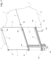
- the solution in Figure 6 relates to a concealed anchor, wherein each panel 5 has a rear frame consisting of two horizontal profiles 16, which are mechanically fixed behind the corresponding plate 7, are identical and spaced vertically from one another: each profile 16 has a fin 17 that protrudes downwards, so as to define, with the rear surface of the plate 7, a horizontal groove 18 used to hang the panel 5 from cross members 20 which form part of the structure 4.
- the variant in Figure 7 relates to a visible anchor, wherein the plates 7 are frameless and are held in a fixed position by clips 16a, 16b, 16c which are fixed to the cross members 20 and are attached to the edges 13, 10 and 11 of the plates 7.
- the structure 4 comprises a plurality of vertical uprights 21, which are aligned and spaced from one another along direction 22, parallel to the wall 2, for example at a predefined constant pitch, on the floor or ground 3.
- the uprights 21 are fixed to the wall 2 by a plurality of anchoring devices 23 and support, in fixed positions, the cross members 20.
- each anchoring device 23 comprises an attachment member 24 having two opposite ends 25 and 26: the end 25 is fixed in a known way (not shown) to the wall 2 (by means of a threaded rod, chemical anchoring, screw anchors, etc.), whereas the end 26 is fixed to a bracket 27 supporting a corresponding upright 21.
- each anchoring device 23 comprises a flange 29 fixed to the end 26 of the attachment member 24, for example by means of a screw or bolt, and a coupling portion 30, which is C-shaped so as to define a seat 31.
- the latter extends in a pass-through manner along a vertical axis 32 and is engaged by a rear portion 33 of the corresponding upright 21.
- the cross-sections of the seat 31 and of the rear portion 33 of the upright 21 do not change along the axis 32.
- the seat 31 has a front opening 34 which is defined by two vertical edges of the portion 30 and has a width, along direction 22, smaller than the rear portion 33 of the upright 21: the latter cannot be inserted or removed horizontally through the opening 34, but must be inserted axially.
- the portion 30 has at least one concave surface 38 defining at least part of the seat 31 and has, in cross-section, an arc-of-a-circle profile, the centre of which coincides with the axis 32.
- the surface 38 is coupled to a corresponding external surface 39 of the rear portion 33, so that the upright 21 can rotate about its axis 32, so as to allow slight adjustments or settlements of its angular position during installation, as will be described below.
- the surface 39 is curved convexly and has, in cross-section, the same arc-of-a-circle profile as the surface 38, i.e., it has a shape that is complementary to the concavely curved shape of the surface 38.
- two surfaces 38 are provided in each bracket 27: these two surfaces 38 face each other along direction 22, are coupled to respective surfaces 39 of the upright 21 and are joined together by a surface 40 at the back of the seat 31.
- the surface 40 in particular, has a protrusion 41 at the centre, which can come into contact with a rear surface 42 of the upright 21, which in turn joins the two surfaces 39.
- the remaining part of the surface 40 of the seat 31 is spaced from the rear surface 42 of the upright 21 to leave the latter free to rotate during installation. This rotation is then stopped by at least one locking element 43, which in this case is defined by a screw or a pin, which crosses the portion 30 of the bracket 27 and the portion 33 of the upright 21, for example at the surfaces 38 and 39.
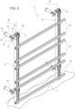
- Each upright 21 also comprises a front portion 44 which emerges through the front openings 34 of the seats 31 and supports at least one vertical graduated bar 45.
- each upright 21 supports a series of graduated bars 45a, 45b, 45c, etc. stacked on top of one another (i.e., vertically aligned and resting on top of one another).
- each bar 45a, 45b, 45c has a series of marks 46 on its own front portion 47, which faces the cross members 20 and the panels 5.
- the marks 46 are vertically spaced from one another in a predefined manner, for example, spaced from one another with a constant pitch, to depict different possible height positions.
- these marks 46 can be defined by notches, dents, lines, protrusions, colourings, etc..., which can also be combined with each other.
- the front portion 47 of the bars 45 protrudes horizontally towards the cross members 20 and the panels 5, with respect to the front portion 44 of the uprights 21.
- the marks 46 include a series of recesses or notches 46a having a predefined height, equal to the vertical size of a rear portion 48 of the cross members 20, and define respective seats engaged by said rear portion 48, and the latter rests against the front portion 44 of the uprights 21.
- the recesses 46a hold the cross members 20 in a fixed vertical position while the cross members 20 are fixed to the uprights 21.
- the vertical distance between the recesses 46a is established at the design stage on the basis of the distance at which the cross members 20 can/must be mounted.
- the marks 46 comprise additional notches 46b, between pairs of consecutive recesses 46a: the notches 46b are arranged so that they are horizontally aligned with the edges 10 of the plates 7, whereby they are used for a visual check of the correct assembly of the cross members 20 and the panels 5 at the end of the installation.
- the graduated bars are standardized and identical to each other.
- the graduated bars 45a are the bottommost ones on the respective uprights 21 and are aligned and arranged at the same height; consequently, the bars 45b of the different uprights 21 are also arranged at the same height (since they rest on the bars 45a), and so on for the bars 45c, etc.
- each graduated bar consists of a single piece, defined by a metal profile.
- it may include a covering element, e.g., made of plastic material.
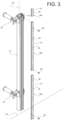
- Figure 5 shows a variant, with different cross-sections for the bar 45 and the upright 21.
- the bars 45 engage a seat 55 formed in the front portion 44 and defined by a vertical groove: in the example in Figure 5 , preferably, the seat 55 has a cross-section shaped so as to guide the bars 45 vertically and hold them in a fixed position along the direction 22, during installation.
- the seat 55 and the bars 45 have a U-shaped cross-section.
- Each bar 45 has a base 56 resting against a back wall 57 of the seat 55. During installation, the bars 45 are arranged on the walls 57 in a vertical reference position and then fixed by means of one or more locking elements 58, visible in Figure 3 (e.g., screws, passing through the base 56 and the wall 57).
- locking elements 58 visible in Figure 3 (e.g., screws, passing through the base 56 and the wall 57).
- the same uprights 21 are connected to the wall 2 by means of the anchoring devices 23 to make the positioning stable.
- the uprights 21 have freedom of rotation in the seats 31, about the respective axes 32, not yet being locked with respect to the brackets 27.
- the bars 45 are then arranged on the uprights 21: their vertical position is adjusted so that the marks 46 provided on the different uprights 21 are aligned horizontally.
- the bottommost bar 45a is positioned first: the vertical positions of all the bars 45a are accurately adjusted and set, for example with levels or other common construction equipment, so that they are all at the same height.
- the bars 45a are fixed to the respective uprights 21 and are then used as a fixed reference to stack the graduated bars 45b, 45c, etc. At this stage, it is no longer necessary to adjust the position of the bars 45b, 45c, etc.... as this position is automatically defined by the latter bars 45b, 45c, etc.... being vertically resting on the bars 45a, which are arranged below and have already been fixed to the uprights 21 (the latter already having a fixed and stable vertical position).
- the marks 46 visible on the different uprights 21 are all accurately aligned horizontally and therefore define a predefined and stable grid for positioning, aligning and assembling the subsequent components of the structure 4.
- the grid consisting of the set of marks 46 represents a template which is available for positioning the cross members 20 at the desired heights and with a precise parallel orientation, without the need to use any other tool to measure the distances and/or to level the same cross members 20. In other words, it is possible to exclusively refer to the marks 46 to mount the cross members 20 in the designed position.
- the position of the uprights 21 in the seats 31 adapts automatically, due to the freedom of rotation described above.
- the uprights 21 can be locked with respect to the brackets 27 by means of the elements 43.
- the panels 5 are mounted on cross members 20 (for example, according to the technique shown in Figure 6 ).
- the bars 45 make it possible to greatly simplify installation operations and reduce operating time: in fact, after arranging the bars 45a at the same height, using the common techniques and tools available on the site, the latter no longer need to be used to position subsequent components (the bars 45b, 45c, the cross members 20, etc.) due to the presence of the reference grid defined by the marks 46, which is visible directly at the front portions 44 of the uprights 21.
- the various components may be fixed using different methods and/or connecting elements other than the screws shown herein.
Landscapes
- Engineering & Computer Science (AREA)
- Architecture (AREA)
- Civil Engineering (AREA)
- Structural Engineering (AREA)
- Finishing Walls (AREA)
Claims (12)
- Tragstruktur (4) für eine hinterlüftete Fassade (1), umfassend:- eine Vielzahl von Pfosten (21), die senkrecht stehen und in horizontaler Richtung (22) voneinander beabstandet sind,- Verankerungsmittel (23) zur Befestigung der Pfosten (21) an einem Gebäude;- eine Vielzahl von Querträgern (20), die parallel zueinander und in unterschiedlichen Höhen angeordnet sind, an den Pfosten (21) befestigt sind und so gestaltet sind, dass sie eine Vielzahl von Paneelen (5) an der Trägerstruktur (4) koppeln und somit die hinterlüftete Fassade (1) bilden;ferner umfassend für jeden Pfosten (21):- mindestens eine Stange (45a), die senkrecht steht und an dem Pfosten (21) angeordnet ist, und- Befestigungsmittel (58), die die Stange (45a) in Bezug auf den Pfosten (21) verriegeln, dadurch gekennzeichnet, dass die mindestens eine Stange (45a) abgestuft ist.
- Tragstruktur nach Anspruch 1,
wobei die abgestuften Stangen (45a) untereinander identisch sind und in der horizontalen Richtung (22) so ausgerichtet sind, dass sie auf gleicher Höhe liegen. - Tragstruktur nach Anspruch 1 oder 2, bei der jeder Pfosten (21) eine Vielzahl von übereinander gestapelten, abgestuften Stangen (45a, 45b, 45c) trägt.
- Tragstruktur nach einem der vorhergehenden Ansprüche, wobei die Pfosten (21) jeweils vertikale Sitze (55) aufweisen, in die die abgestuften Stangen (45) eingreifen.
- Tragstruktur nach einem der vorhergehenden Ansprüche, wobei die abgestuften Stangen (45) einen vorderen Abschnitt (47) aufweisen, der horizontal in Richtung der Querträger (20) in Bezug auf den entsprechenden Pfosten (21) vorsteht und eine Reihe von Vertiefungen (46a) definiert, die vertikal voneinander beabstandet sind und eine vordefinierte Höhe aufweisen, die gleich der vertikalen Größe eines hinteren Abschnitts (48) der Querträger (20) ist; und wobei die Vertiefungen (46a) mit den hinteren Abschnitten (48) der Querträger (20) in Eingriff stehen.
- Tragstruktur nach einem der vorhergehenden Ansprüche, wobei die Verankerungsmittel (23) eine Vielzahl von Trägern (27) umfassen, die entsprechende Sitze (31) definieren, in die die Pfosten (21) eingreifen; wobei die Sitze (31) so geformt sind, dass sie den Pfosten (21) eine Drehfreiheit um entsprechende vertikale Achsen (32) in den Sitzen (31) lassen; wobei ferner Befestigungsmittel (43) vorgesehen sind, um die Pfosten in Bezug auf die Träger (27) zu verriegeln.
- Tragstruktur nach Anspruch 6,
wobei die Sitze (31) jeweils konkave Flächen (38) mit kreisbogenförmigen Querschnitten aufweisen. - Tragstruktur nach Anspruch 6 oder 7, wobei die Sitze (31) jeweils vordere Öffnungen (34) aufweisen, deren Breite in der horizontalen Richtung (22) kleiner ist als die der Pfosten (21).
- Hinterlüftete Fassade (1) umfassend eine Tragstruktur (4), die zur Befestigung an einem Gebäude bestimmt ist, und eine Vielzahl von Paneelen (7), die mit der Tragstruktur (4) verbunden sind, dadurch gekennzeichnet, dass die Tragstruktur (4) einem der vorhergehenden Ansprüche entspricht.
- Verfahren zur Installation einer Tragstruktur (4) nach einem der Ansprüche 1 bis 8, wobei das Verfahren die folgenden Schritte umfasst:- Anordnen der Pfosten (21) vertikal vor einem Gebäude in Positionen, die in horizontaler Richtung (22) ausgerichtet und voneinander beabstandet sind,- Verankern der Pfosten (21) am Gebäude;- Anordnen der Querträger (20) auf den Pfosten (21) in unterschiedlichen Höhen und in horizontalen Positionen parallel zueinander;- Befestigen der Querträger (20) an den Pfosten (21);dadurch gekennzeichnet, dass das Verfahren außerdem die folgenden Schritte umfasst:- Vorsehen mindestens einer abgestuften Stange (45a) auf jedem Pfosten (21);- vor dem Anordnen und Befestigen der Querträger (20), Einstellen der vertikalen Position der abgestuften Stange (45a) für jeden Pfosten (21) und Befestigen der Messlatten an den entsprechenden Pfosten (21);- Bezugnehmen auf die abgestuften Stangen, um die Querträger (20) anzuordnen.
- Verfahren nach Anspruch 10, umfassend den Schritt
des Stapelns einer Vielzahl von abgestuften Stangen (45a, 45b, 45c) für jeden der Pfosten (21), bevor die Querträger (20) angeordnet und befestigt werden. - Verfahren nach Anspruch 10 oder 11, wobei die
abgestufte Stangen (45) einen vorderen Abschnitt (47) aufweisen, der nach dem Befestigungsschritt horizontal in Bezug auf den entsprechenden Pfosten (21) vorsteht; wobei der vordere Abschnitt (47) eine Reihe von Vertiefungen (46a) definiert, die vertikal voneinander beabstandet sind und eine vordefinierte Höhe aufweisen, die gleich der vertikalen Größe eines hinteren Abschnitts (48) der Querträger (20) ist; und wobei der Schritt des Anordnens der Querträger (20) das Einsetzen der hinteren Abschnitte (48) der Querträger (20) in die Vertiefungen (46a) umfasst.
Applications Claiming Priority (1)
| Application Number | Priority Date | Filing Date | Title |
|---|---|---|---|
| IT102022000005867A IT202200005867A1 (it) | 2022-03-24 | 2022-03-24 | Struttura di supporto e metodo di installazione per realizzare una facciata ventilata |
Publications (3)
| Publication Number | Publication Date |
|---|---|
| EP4249701A1 EP4249701A1 (de) | 2023-09-27 |
| EP4249701C0 EP4249701C0 (de) | 2024-10-30 |
| EP4249701B1 true EP4249701B1 (de) | 2024-10-30 |
Family
ID=81927598
Family Applications (1)
| Application Number | Title | Priority Date | Filing Date |
|---|---|---|---|
| EP23163646.5A Active EP4249701B1 (de) | 2022-03-24 | 2023-03-23 | Tragkonstruktion und montageverfahren zur herstellung einer belüfteten fassade |
Country Status (3)
| Country | Link |
|---|---|
| EP (1) | EP4249701B1 (de) |
| ES (1) | ES2993910T3 (de) |
| IT (1) | IT202200005867A1 (de) |
Family Cites Families (1)
| Publication number | Priority date | Publication date | Assignee | Title |
|---|---|---|---|---|
| KR20180016697A (ko) * | 2016-08-05 | 2018-02-19 | 주식회사 포스코 | 패널 고정 장치 및 이를 사용한 패널 고정 방법 |
-
2022
- 2022-03-24 IT IT102022000005867A patent/IT202200005867A1/it unknown
-
2023
- 2023-03-23 ES ES23163646T patent/ES2993910T3/es active Active
- 2023-03-23 EP EP23163646.5A patent/EP4249701B1/de active Active
Also Published As
| Publication number | Publication date |
|---|---|
| EP4249701A1 (de) | 2023-09-27 |
| EP4249701C0 (de) | 2024-10-30 |
| ES2993910T3 (en) | 2025-01-13 |
| IT202200005867A1 (it) | 2023-09-24 |
Similar Documents
| Publication | Publication Date | Title |
|---|---|---|
| US10422140B2 (en) | Screen enclosure support assembly | |
| US5657593A (en) | Mounting bracket and mounting system | |
| US10745902B1 (en) | Framing systems and brackets therefor | |
| CN103154393A (zh) | 展异的建筑结构改良 | |
| CN114197799B (zh) | 一种展览馆内饰节能石板干挂结构及安装方法 | |
| EP4249701B1 (de) | Tragkonstruktion und montageverfahren zur herstellung einer belüfteten fassade | |
| US20230358029A1 (en) | Balcony | |
| US20060032157A1 (en) | Seismic wall system | |
| EP3216935A1 (de) | Trennwandverbindungssysteme und -verfahren | |
| CN109914728B (zh) | 一种墙板与层板的挂装结构 | |
| EP1882791A2 (de) | Modulare Tafel zur Herstellung belüfteter Gebäudefassaden | |
| JP2000257205A (ja) | 二重天井下地構造およびその施工方法 | |
| JP5969894B2 (ja) | パネル取付構造 | |
| EP3635191B1 (de) | Bausystem für wandverkleidung | |
| IE46564B1 (en) | Attaching stone cladding panels to structural walls | |
| RU36847U1 (ru) | Комплект для крепления фасадных облицовочных панелей (варианты), опорный узел и навесной элемент для него | |
| WO2022153083A1 (en) | Fastening system for parapets or fences and related parapet or fence | |
| KR100414677B1 (ko) | 조립식 패널 설치 시스템 | |
| KR200247957Y1 (ko) | 조립식 패널 설치 시스템 | |
| KR102740851B1 (ko) | 건축 내외장재 시공용 하지틀구조 | |
| CN221118894U (zh) | 用于建筑幕墙的连接结构及建筑幕墙 | |
| CA3133907C (en) | SUSPENDED WALL AND CEILING SYSTEM | |
| CN215483535U (zh) | 集成装配式钢结构建筑 | |
| JPH08165720A (ja) | ユニット式建物及びその建築方法 | |
| JPH0122826Y2 (de) |
Legal Events
| Date | Code | Title | Description |
|---|---|---|---|
| PUAI | Public reference made under article 153(3) epc to a published international application that has entered the european phase |
Free format text: ORIGINAL CODE: 0009012 |
|
| STAA | Information on the status of an ep patent application or granted ep patent |
Free format text: STATUS: THE APPLICATION HAS BEEN PUBLISHED |
|
| AK | Designated contracting states |
Kind code of ref document: A1 Designated state(s): AL AT BE BG CH CY CZ DE DK EE ES FI FR GB GR HR HU IE IS IT LI LT LU LV MC ME MK MT NL NO PL PT RO RS SE SI SK SM TR |
|
| STAA | Information on the status of an ep patent application or granted ep patent |
Free format text: STATUS: REQUEST FOR EXAMINATION WAS MADE |
|
| 17P | Request for examination filed |
Effective date: 20240318 |
|
| RAX | Requested extension states of the european patent have changed |
Extension state: BA Payment date: 20240318 |
|
| RBV | Designated contracting states (corrected) |
Designated state(s): AL AT BE BG CH CY CZ DE DK EE ES FI FR GB GR HR HU IE IS IT LI LT LU LV MC ME MK MT NL NO PL PT RO RS SE SI SK SM TR |
|
| RIC1 | Information provided on ipc code assigned before grant |
Ipc: E04F 13/08 20060101AFI20240403BHEP |
|
| GRAP | Despatch of communication of intention to grant a patent |
Free format text: ORIGINAL CODE: EPIDOSNIGR1 |
|
| STAA | Information on the status of an ep patent application or granted ep patent |
Free format text: STATUS: GRANT OF PATENT IS INTENDED |
|
| INTG | Intention to grant announced |
Effective date: 20240524 |
|
| GRAS | Grant fee paid |
Free format text: ORIGINAL CODE: EPIDOSNIGR3 |
|
| GRAA | (expected) grant |
Free format text: ORIGINAL CODE: 0009210 |
|
| STAA | Information on the status of an ep patent application or granted ep patent |
Free format text: STATUS: THE PATENT HAS BEEN GRANTED |
|
| AK | Designated contracting states |
Kind code of ref document: B1 Designated state(s): AL AT BE BG CH CY CZ DE DK EE ES FI FR GB GR HR HU IE IS IT LI LT LU LV MC ME MK MT NL NO PL PT RO RS SE SI SK SM TR |
|
| REG | Reference to a national code |
Ref country code: GB Ref legal event code: FG4D |
|
| REG | Reference to a national code |
Ref country code: CH Ref legal event code: EP |
|
| REG | Reference to a national code |
Ref country code: IE Ref legal event code: FG4D |
|
| REG | Reference to a national code |
Ref country code: DE Ref legal event code: R096 Ref document number: 602023000851 Country of ref document: DE |
|
| U01 | Request for unitary effect filed |
Effective date: 20241104 |
|
| U07 | Unitary effect registered |
Designated state(s): AT BE BG DE DK EE FI FR IT LT LU LV MT NL PT RO SE SI Effective date: 20241114 |
|
| REG | Reference to a national code |
Ref country code: ES Ref legal event code: FG2A Ref document number: 2993910 Country of ref document: ES Kind code of ref document: T3 Effective date: 20250113 |
|
| PG25 | Lapsed in a contracting state [announced via postgrant information from national office to epo] |
Ref country code: IS Free format text: LAPSE BECAUSE OF FAILURE TO SUBMIT A TRANSLATION OF THE DESCRIPTION OR TO PAY THE FEE WITHIN THE PRESCRIBED TIME-LIMIT Effective date: 20250228 Ref country code: HR Free format text: LAPSE BECAUSE OF FAILURE TO SUBMIT A TRANSLATION OF THE DESCRIPTION OR TO PAY THE FEE WITHIN THE PRESCRIBED TIME-LIMIT Effective date: 20241030 |
|
| U20 | Renewal fee for the european patent with unitary effect paid |
Year of fee payment: 3 Effective date: 20250311 |
|
| PG25 | Lapsed in a contracting state [announced via postgrant information from national office to epo] |
Ref country code: NO Free format text: LAPSE BECAUSE OF FAILURE TO SUBMIT A TRANSLATION OF THE DESCRIPTION OR TO PAY THE FEE WITHIN THE PRESCRIBED TIME-LIMIT Effective date: 20250130 |
|
| PG25 | Lapsed in a contracting state [announced via postgrant information from national office to epo] |
Ref country code: GR Free format text: LAPSE BECAUSE OF FAILURE TO SUBMIT A TRANSLATION OF THE DESCRIPTION OR TO PAY THE FEE WITHIN THE PRESCRIBED TIME-LIMIT Effective date: 20250131 |
|
| PG25 | Lapsed in a contracting state [announced via postgrant information from national office to epo] |
Ref country code: PL Free format text: LAPSE BECAUSE OF FAILURE TO SUBMIT A TRANSLATION OF THE DESCRIPTION OR TO PAY THE FEE WITHIN THE PRESCRIBED TIME-LIMIT Effective date: 20241030 |
|
| PG25 | Lapsed in a contracting state [announced via postgrant information from national office to epo] |
Ref country code: RS Free format text: LAPSE BECAUSE OF FAILURE TO SUBMIT A TRANSLATION OF THE DESCRIPTION OR TO PAY THE FEE WITHIN THE PRESCRIBED TIME-LIMIT Effective date: 20250130 |
|
| PG25 | Lapsed in a contracting state [announced via postgrant information from national office to epo] |
Ref country code: SM Free format text: LAPSE BECAUSE OF FAILURE TO SUBMIT A TRANSLATION OF THE DESCRIPTION OR TO PAY THE FEE WITHIN THE PRESCRIBED TIME-LIMIT Effective date: 20241030 |
|
| PGFP | Annual fee paid to national office [announced via postgrant information from national office to epo] |
Ref country code: ES Payment date: 20250423 Year of fee payment: 3 |
|
| PG25 | Lapsed in a contracting state [announced via postgrant information from national office to epo] |
Ref country code: SK Free format text: LAPSE BECAUSE OF FAILURE TO SUBMIT A TRANSLATION OF THE DESCRIPTION OR TO PAY THE FEE WITHIN THE PRESCRIBED TIME-LIMIT Effective date: 20241030 |
|
| PG25 | Lapsed in a contracting state [announced via postgrant information from national office to epo] |
Ref country code: CZ Free format text: LAPSE BECAUSE OF FAILURE TO SUBMIT A TRANSLATION OF THE DESCRIPTION OR TO PAY THE FEE WITHIN THE PRESCRIBED TIME-LIMIT Effective date: 20241030 |
|
| PLBE | No opposition filed within time limit |
Free format text: ORIGINAL CODE: 0009261 |
|
| STAA | Information on the status of an ep patent application or granted ep patent |
Free format text: STATUS: NO OPPOSITION FILED WITHIN TIME LIMIT |
|
| 26N | No opposition filed |
Effective date: 20250731 |
|
| PG25 | Lapsed in a contracting state [announced via postgrant information from national office to epo] |
Ref country code: MC Free format text: LAPSE BECAUSE OF FAILURE TO SUBMIT A TRANSLATION OF THE DESCRIPTION OR TO PAY THE FEE WITHIN THE PRESCRIBED TIME-LIMIT Effective date: 20241030 |
|
| PG25 | Lapsed in a contracting state [announced via postgrant information from national office to epo] |
Ref country code: IE Free format text: LAPSE BECAUSE OF NON-PAYMENT OF DUE FEES Effective date: 20250323 |
|
| U20 | Renewal fee for the european patent with unitary effect paid |
Year of fee payment: 4 Effective date: 20260203 |
|
| REG | Reference to a national code |
Ref country code: CH Ref legal event code: U11 Free format text: ST27 STATUS EVENT CODE: U-0-0-U10-U11 (AS PROVIDED BY THE NATIONAL OFFICE) Effective date: 20260401 |