EP4249689A1 - Duschanordnung - Google Patents
Duschanordnung Download PDFInfo
- Publication number
- EP4249689A1 EP4249689A1 EP22176084.6A EP22176084A EP4249689A1 EP 4249689 A1 EP4249689 A1 EP 4249689A1 EP 22176084 A EP22176084 A EP 22176084A EP 4249689 A1 EP4249689 A1 EP 4249689A1
- Authority
- EP
- European Patent Office
- Prior art keywords
- plug
- sprayhead
- quick
- release
- section
- Prior art date
- Legal status (The legal status is an assumption and is not a legal conclusion. Google has not performed a legal analysis and makes no representation as to the accuracy of the status listed.)
- Withdrawn
Links
Images





Classifications
-
- B—PERFORMING OPERATIONS; TRANSPORTING
- B05—SPRAYING OR ATOMISING IN GENERAL; APPLYING FLUENT MATERIALS TO SURFACES, IN GENERAL
- B05B—SPRAYING APPARATUS; ATOMISING APPARATUS; NOZZLES
- B05B1/00—Nozzles, spray heads or other outlets, with or without auxiliary devices such as valves, heating means
- B05B1/14—Nozzles, spray heads or other outlets, with or without auxiliary devices such as valves, heating means with multiple outlet openings; with strainers in or outside the outlet opening
- B05B1/18—Roses; Shower heads
-
- E—FIXED CONSTRUCTIONS
- E03—WATER SUPPLY; SEWERAGE
- E03C—DOMESTIC PLUMBING INSTALLATIONS FOR FRESH WATER OR WASTE WATER; SINKS
- E03C1/00—Domestic plumbing installations for fresh water or waste water; Sinks
- E03C1/02—Plumbing installations for fresh water
- E03C1/04—Water-basin installations specially adapted to wash-basins or baths
- E03C1/0408—Water installations especially for showers
-
- B—PERFORMING OPERATIONS; TRANSPORTING
- B05—SPRAYING OR ATOMISING IN GENERAL; APPLYING FLUENT MATERIALS TO SURFACES, IN GENERAL
- B05B—SPRAYING APPARATUS; ATOMISING APPARATUS; NOZZLES
- B05B1/00—Nozzles, spray heads or other outlets, with or without auxiliary devices such as valves, heating means
- B05B1/14—Nozzles, spray heads or other outlets, with or without auxiliary devices such as valves, heating means with multiple outlet openings; with strainers in or outside the outlet opening
- B05B1/20—Perforated pipes or troughs, e.g. spray booms; Outlet elements therefor
-
- B—PERFORMING OPERATIONS; TRANSPORTING
- B05—SPRAYING OR ATOMISING IN GENERAL; APPLYING FLUENT MATERIALS TO SURFACES, IN GENERAL
- B05B—SPRAYING APPARATUS; ATOMISING APPARATUS; NOZZLES
- B05B1/00—Nozzles, spray heads or other outlets, with or without auxiliary devices such as valves, heating means
- B05B1/30—Nozzles, spray heads or other outlets, with or without auxiliary devices such as valves, heating means designed to control volume of flow, e.g. with adjustable passages
- B05B1/3026—Gate valves; Sliding valves; Cocks
-
- B—PERFORMING OPERATIONS; TRANSPORTING
- B05—SPRAYING OR ATOMISING IN GENERAL; APPLYING FLUENT MATERIALS TO SURFACES, IN GENERAL
- B05B—SPRAYING APPARATUS; ATOMISING APPARATUS; NOZZLES
- B05B12/00—Arrangements for controlling delivery; Arrangements for controlling the spray area
- B05B12/002—Manually-actuated controlling means, e.g. push buttons, levers or triggers
-
- E—FIXED CONSTRUCTIONS
- E03—WATER SUPPLY; SEWERAGE
- E03C—DOMESTIC PLUMBING INSTALLATIONS FOR FRESH WATER OR WASTE WATER; SINKS
- E03C1/00—Domestic plumbing installations for fresh water or waste water; Sinks
- E03C1/02—Plumbing installations for fresh water
- E03C1/04—Water-basin installations specially adapted to wash-basins or baths
- E03C1/0408—Water installations especially for showers
- E03C1/0409—Shower handles
-
- E—FIXED CONSTRUCTIONS
- E03—WATER SUPPLY; SEWERAGE
- E03C—DOMESTIC PLUMBING INSTALLATIONS FOR FRESH WATER OR WASTE WATER; SINKS
- E03C1/00—Domestic plumbing installations for fresh water or waste water; Sinks
- E03C1/02—Plumbing installations for fresh water
- E03C1/06—Devices for suspending or supporting the supply pipe or supply hose of a shower-bath
-
- F—MECHANICAL ENGINEERING; LIGHTING; HEATING; WEAPONS; BLASTING
- F16—ENGINEERING ELEMENTS AND UNITS; GENERAL MEASURES FOR PRODUCING AND MAINTAINING EFFECTIVE FUNCTIONING OF MACHINES OR INSTALLATIONS; THERMAL INSULATION IN GENERAL
- F16L—PIPES; JOINTS OR FITTINGS FOR PIPES; SUPPORTS FOR PIPES, CABLES OR PROTECTIVE TUBING; MEANS FOR THERMAL INSULATION IN GENERAL
- F16L37/00—Couplings of the quick-acting type
- F16L37/28—Couplings of the quick-acting type with fluid cut-off means
- F16L37/38—Couplings of the quick-acting type with fluid cut-off means with fluid cut-off means in only one of two pipe-end fittings
- F16L37/40—Couplings of the quick-acting type with fluid cut-off means with fluid cut-off means in only one of two pipe-end fittings with a lift valve being opened automatically when the coupling is applied
Definitions
- the present invention relates generally to a sanitary device, and more particularly to a sprayhead assembly including the sprayhead and the shower columns.
- the shower column could be disposed with a lifting seat for adjusting the height, and the fixing seat for fixing the spray head is disposed on the lifting seat.
- the conventional sanitary device including the sprayhead and the shower column does not have a common flow pathway that communicates the sprayhead and the shower column.
- the conventional sanitary device includes two independent flow pathways that are connected to the sprayhead and the shower column, respectively, so that each of the sprayhead and the shower column provides a water spray function. Therefore, the conventional sanitary device has problems that the connection between the sprayhead and the shower column does not appear integral, and the two independent flow pathways for providing water increase the manufacturing cost.
- the primary objective of the present invention is to provide a sanitary installation includes a sprayhead and a shower column, wherein the shower column is detachably engaged with the sprayhead, and the shower column and the sprayhead share the same flow pathway.
- the sprayhead could prevent the water flow from flowing out through a connecting portion that is adapted to connected to the shower column. Therefore, the sprayhead assembly provided to the user appears smooth and integral and has two different output functions (namely outputting by the sprayhead and the shower column). Besides, the manufacturing cost of the sprayhead assembly could be reduced.
- the present invention provides a sprayhead assembly including a sprayhead and a shower column.
- the sprayhead includes a tube body, a quick-release seat, and a plug, wherein an interior of the sprayhead forms a flow pathway.
- the flow pathway has an inlet.
- a top end of the tube body has a mounted opening.
- the tube body is disposed with a plurality of nozzles that communicates with the flow pathway.
- the quick-release seat is embedded into the mounted opening, wherein an inserted hole is formed in the middle of the quick-release seat, and the inserted hole has a plug hole section. A portion of the plug passes through the plug hole section.
- the shower column includes a quick-release connector, a connecting tube, and a top spray head, wherein the quick-release connector is connected to a bottom end of the connecting tube, and the top spray head is connected to a top end of the connecting tube.
- the quick-release connector has a guiding hole.
- the entire sprayhead assembly looks integral and aesthetic, and the shower column and the sprayhead could be used as one.
- the plug and the quick-release connector when the shower column is engaged with the sprayhead, the shower column and the sprayhead could be communicated via the same flow pathway for providing water. It is not necessary to add another flow pathway for providing water to the shower column, thereby reducing the manufacturing cost.
- the plug When the shower column is disengaged from the sprayhead, the plug could immediately block the plug hole section of the inserted hole of the quick-release seat, so that the water in the sprayhead does not leak from the inserted hole of the quick-release seat. Therefore, the user could use the sprayhead individually to take a shower as well, which is convenient for the user.
- a sprayhead assembly 100 of an embodiment according to the present invention includes a sprayhead 10 and a shower column 20 that is detachably connected to the sprayhead 10. Additionally, a shut-off structure is disposed between the sprayhead 10 and the shower column 20 to cut off a water flow when the shower column 20 is detached from the sprayhead 10, so that the sprayhead 10 could still be used without the shower column 20 by a user to take a shower. In other words, a function of the sprayhead 10 does not affect by the disassembly of the shower column 20.
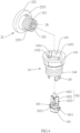
- the sprayhead 10 includes a tube body 12, a quick-release seat 14, and a plug 16.
- An interior of the sprayhead 10 forms a flow pathway A.
- a bottom end of the flow pathway A has an inlet A1.
- a top end of the tube body 12 has a mounted opening 121.
- a front side of the tube body 12 has a plurality of nozzles 122 and a control button 123.
- Each of the nozzles 122 is communicates with the flow pathway A.
- the control button 123 controls a water output through each of the nozzles 122.
- the quick-release seat 14 is embedded into the mounted opening 121 by adhering or welding.
- the quick-release seat 14 has an inserted hole 141 inside.
- a bottom end of the inserted hole 141 has a plug hole section 142 for receiving the plug 16, wherein a diameter of the plug hole section 142 is smaller than a diameter of the inserted hole 14, and an end of the plug hole section 142 forms an opening on the center of a bottom surface of the quick-release seat 14.
- a portion of the plug 16 is inserted into the plug hole section 142 of the inserted hole 141.
- the plug 16 is movable along a wall of the plug hole section 142 to move between a first position and a second position, wherein the first position and the second position are located at different heights.
- a support 18 is disposed within the flow pathway A and has a spring seat 181.
- the spring seat 181 is disposed with a spring 182, wherein the spring 182 is adapted to urge the plug 16 to move toward the first position.
- the shower column 20 includes a quick-release connector 22, a connecting tube 24, and a top spray head 26.
- the quick-release connector 22 is connected to a bottom end of the connecting tube 24 by adhering or welding.
- the top spray head 26 is connected and fixed to a top end of the connecting tube 24.
- the quick-release connector 22 has a guiding hole 221.
- an outer surface of the quick-release connector 22 has an external thread
- the inner surface of the quick-release seat 14 has an internal thread, so that the quick-release connector 22 is detachably engaged with the quick-release seat 14 by screwing.
- the outer surface of the quick-release connector 22 has a protrusion
- the inner surface of the quick-release seat 14 has a slot, so that the quick-release connector 22 is detachably engaged with the quick-release seat 14 by interlocking the protrusion and the slot.
- An inner wall of the guiding hole 221 of the quick-release connector 22 is connected to a pressing structure 28.
- the pressing structure 28 pushes the plug 16 at a top end to move to the second position.
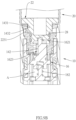
- the flow pathway A communicates with the guiding hole 221 having the plug hole section 142, so that a water flow flowing through the flow pathway A could enter into the connecting tube 24 of the shower column 20 and then be outputted through the top spray head 26.
- the shower column 20 When the shower column 20 of the abovementioned embodiment is used, the shower column 20 is fixed to a wall of a bathroom via a holder mounted on the wall, and the inlet A1 of the shower column 20 is connected to a water source.
- the flow pathway A is utilized by both the shower column 20 and the sprayhead 10, so that the shower column 20 does not need to be disposed with an additional input flow pathway for the shower column 20.
- FIG. 1 , FIG. 5 , and FIG. 6 when the user switches the control button 123 to allow the water in the flow pathway A could flow to the nozzles 122 of the top spray head 26, the nozzles 122 of the sprayhead 10 and the top spray head 26 of the shower column 20 output the water.
- the spring 182 urges the plug 16 to return to the first position, thereby blocking the plug hole section 142 and preventing the water flow in the flow pathway A from flowing through the quick-release seat 14.
- the user could still operate the control button 123 to allow the water flow through out the nozzles 122 of the sprayhead 10.
- a portion of an inner surface of the tube body 12 that is adjacent to the mounted opening 121 has an annular projection 124 in a ring shape.
- the quick-release seat 14 which is a vertical tube, has a lower disc portion 143 at a top side and a tube portion 144 at a bottom side. An outer diameter of the lower disc portion 143 is greater than an outer diameter of the tube portion 144.
- the tube portion 144 passes through the annular projection 124. A bottom edge of the lower disc portion 143 abuts against the annular projection 124 to position.
- the inserted hole 141 is a stepped hole. Except for the plug hole section 142 for receiving the plug 16, the inserted hole 141 has a top section and a middle section, wherein the middle section is located between the top section and the plug hole section 142 for receiving the plug 16.
- the top section of the inserted hole 141 communicates outside, and a diameter of the top section is greater than a diameter of the middle section.
- a top portion of an inner surface of the lower disc portion 143 has a plurality of first grooves 1431.
- the inner surface of the lower disc portion 143 has two first grooves 1431 which are opposite to each other, and each of the first grooves 1431 extends in a direction parallel to an axial direction of the quick-release seat 14.
- Each of the first grooves 1431 has an opening on a top surface of the lower disc portion 143, and an end of each of the first grooves 1431, which is away from the top surface of the lower disc portion 143, is connected to a second groove 1432.
- the second grooves 1432 extend along a circumferential direction of the lower disc portion 143, wherein each of the second grooves 1432 extends in the same circumferential direction of the lower disc portion 143 from one of the first grooves1431.
- a bottom surface of the tube portion 44 has a plurality of guiding rods 145 extending downward.
- the plurality of guiding rods 145 includes two pairs of guiding rods 145 that are opposite to each other.
- the plug 16 includes a bottom section 161, a top section 162, and a plugging portion 163.
- the plugging portion 163 is connected between the bottom section 161 and the top section 162.
- Two projecting lugs 1611 protrude in a radial direction on a circumference of the bottom section 161, wherein the two projecting lugs 1611 extend in two opposite directions.
- Each of the two projecting lugs 1611 is inserted into a space between adjacent two of the guiding rods 145, so that the two projecting lugs 1611 are guided and restricted by the guiding rods 145, thereby allowing the plug 16 to smoothly moved along the axial direction without rotating.
- a bottom surface of the bottom section 161 has a plug recess 1612, wherein a top end of the spring 182 is inserted into and urges against the plug recess 1612.
- a center of the top section 162 of the plug 16 is disposed with a supporting rod 1621.
- a center of the pressing structure 28 abuts against a top end of the supporting rod 1621.
- a circumference of the supporting rod 1621 is connected to a plurality of blades 1622 that are arranged around the supporting rod 1621 and extend radially.
- a height of a top edge of each of the blades 1622 is lower than a height of the top end of the supporting rod 1621.
- a bottom edge of each of the blades 1622 is connected to the plugging portion 163.
- a plurality of guiding grooves 1623 is formed between adjacent two of the blades 1622, that is to say, any adjacent two of the guiding grooves 1623 are separated by one of the blades 1622.
- Each of the guiding grooves 1623 extends in a direction parallel to an axis of the plug 16.
- a circumference of the plugging portion 163 is embedded with a sealing ring 1631, wherein the sealing ring 1631 is adapted to be inserted into the plug hole section 142 of the inserted hole 141 to block the plug hole section 142.
- the plugging portion 163 is inserted into the plug hole section 142 to block the plug hole section 142.
- the plug 16 is moved in a direction toward the spring seat 181, thereby allowing the plugging portion 163 to be disengaged from the plug hole section 142 of the inserted hole 141.
- the plug hole section 142 of the inserted hole 141 is unblocked, so that the guiding grooves 1623 communicate with the plug hole section 142 of the inserted hole 141, thereby communicating the flow pathway A and the guiding hole 221 via the guiding grooves 1623.
- a sectional area of the guiding grooves 1623 is smaller than either a sectional area of the guiding hole 221 or a sectional area of the flow pathway A, so that the water flow passing through the guiding grooves 1623 to the shower column 20 is stable and constant, thereby preventing the water from splashing at the connecting site between the shower column 20 and the sprayhead 10 when the shower column 20 is detached from the sprayhead 10.
- the quick-release connector 22 is a vertical tube body and is divided into an upper disc portion 222 and an inserting tube portion 223 along a top-bottom direction namely a direction from the connecting tube 24 to the tube body 12 of the sprayhead 10 .
- An outer diameter of the upper disc portion 222 is greater than an outer diameter of the inserting tube portion 223.
- the upper disc portion 222 is fixed and embedded into a bottom end of the connecting tube 24.
- the inserting tube portion 223 has an upper section and a lower section, wherein the upper section is located between the upper disc portion 222 and the lower section, and an outer diameter of the upper section of the inserting tube portion 223 is greater than an outer diameter of the lower section of the inserting tube portion 223.
- the inserting tube portion 223 When the quick-release connector 22 is engaged with the quick-release seat 14, the inserting tube portion 223 is inserted into the inserted hole 141 of the quick-release seat 14.
- An circumference of the top section of the inserting tube portion 223 has two protruding hooks 2231 protruding away from the circumference of the inserting tube portion 223 and extending in opposite directions, wherein the two protruding hooks 2231 correspond to the two first grooves 1431 of the lower disc portion 143.
- the number of the protruding hooks 2231 and the number of the first grooves 1431 are not limited to two, as long as the number of the protruding hooks 2231 corresponds to the number of the first grooves 1431. As illustrated in FIG. 9A to FIG.
- each of the protruding hooks 2231 is inserted into one of the first grooves 1431 from the top and then is moved along the second groove 1432 to a closed end of the second groove 1432 to position, thereby allowing the upper disc portion 222 abuts against and is fixed to the lower disc portion 143.
- an interior of the tube body 12 is embedded with an upper flow channel 13 from top and a lower flow channel 15 from the bottom.
- a top end of the upper flow channel 13 has a top annular portion 131, and a bottom end of the upper flow channel 13 has a bottom annular portion 132.
- the tube portion 144 of the quick-release seat 14 is sealedly inserted into (namely tightly fitted into) the top annular portion 131 to position.
- a top end of the lower flow channel 15 has a connecting tube portion 151, wherein the connecting tube portion 151 is sealedly inserted into the bottom annular portion 132 to fix.
- a bottom end of the lower flow channel 15 has a threaded tube portion 152, wherein the threaded tube portion 152 protrudes away from a bottom end of the tube body 12, and the inlet A1 is located at a bottom end of the threaded tube portion 152.
- the flow pathway A is located in the upper flow channel 13 and the lower flow channel 15.
- a front side of the tube body 12 includes the nozzles 122 that are spaced and arranged in the top-bottom direction, namely a direction from the mounted opening 121 to the inlet A1.
- the nozzles 122 are located in front of the upper flow channel 13.
- An inner wall of the front side of the tube body 12 includes a plurality of protruding tubes 125 that protrude inward from the inner wall. Each of the nozzles 122 communicates with one of the protruding tubes 125.
- a front side of the upper flow channel 13 is disposed with a plurality of grooves 133 that are spaced and arranged in the top-bottom direction. As illustrated in FIG.
- each of the protruding tubes 125 is embedded into one of the grooves 133, wherein each of the grooves 133 communicates with the flow pathway A via an output aperture 134.
- the front side of the upper flow channel 13 is disposed with groups of three output apertures 134, wherein a position of each of the groups of three apertures corresponds to a position of one of the grooves 133, so that each of the grooves 133 communicates with the flow pathway A via one of the groups of the output apertures 134.
- the support 18 is connected to an inner surface of the upper flow channel 13 and is located in the flow pathway A.
- the spring seat 181 has a central rod 183, and the spring 182 fits around the central rod 183. When the plug 16 is moved to the second position, a portion of the central rod 183 is received in the plug recess 1612.
- a rear side of the tube body 12 has a receiving opening 126, wherein a position of the receiving opening 126 is behind the upper flow channel 13, that is to say the receiving opening 126 and the nozzles 122 face opposite directions. A size of the receiving opening 126 allows the upper flow channel 13 to pass through.
- the receiving opening 126 is detachably engaged with a back cover 127 to seal the receiving opening 126.
- a top portion of the lower flow channel 15 is disposed with a controlling valve 153.
- the front side of the tube body 12 has a recess 128 for receiving the control button 123.
- the recess 128 for receiving the control button 123 is aligned with the plurality of nozzles in the top-bottom direction.
- the control button 123 is a pressed button that could be received in the recess 128.
- the control button 123 is engaged with a front side of the controlling valve 153 by fitting.
- the controlling valve 153 is a switch that is operated by pressing. Normally, the controlling valve 153 blocks the water flow flowing from the inlet A1 in the flow pathway A. When the controlling valve 153 is pressed, the flow pathway A is unblocked, thereby allowing the water flow to pass through the flow pathway A and flow to the nozzles 122.
- the controlling valve 153 could be a valve for controlling the flow volume. The flow volume controlling valve could control a volume of water flow that could pass through the flow pathway A and flow to the nozzles 122.
- the control button 123 is a knob that is engaged with the flow volume controlling valve.
- controlling valve 153 and the control button 123 could be omitted from the sprayhead 10. Therefore, the function of the controlling valve 153 and the control button 123 is replaced by a controlling device for controlling the provision of the water resource.
- the controlling device could be a faucet, wherein the faucet could control the provision of the water flow that flows through the flow pathway A and outputs through nozzles 122.
Landscapes
- Health & Medical Sciences (AREA)
- Life Sciences & Earth Sciences (AREA)
- Engineering & Computer Science (AREA)
- Hydrology & Water Resources (AREA)
- Public Health (AREA)
- Water Supply & Treatment (AREA)
- Nozzles (AREA)
- Bathtubs, Showers, And Their Attachments (AREA)
Applications Claiming Priority (1)
| Application Number | Priority Date | Filing Date | Title |
|---|---|---|---|
| CN202210304717.XA CN116809254A (zh) | 2022-03-22 | 2022-03-22 | 组合式花洒 |
Publications (1)
| Publication Number | Publication Date |
|---|---|
| EP4249689A1 true EP4249689A1 (de) | 2023-09-27 |
Family
ID=82021148
Family Applications (1)
| Application Number | Title | Priority Date | Filing Date |
|---|---|---|---|
| EP22176084.6A Withdrawn EP4249689A1 (de) | 2022-03-22 | 2022-05-30 | Duschanordnung |
Country Status (2)
| Country | Link |
|---|---|
| EP (1) | EP4249689A1 (de) |
| CN (1) | CN116809254A (de) |
Citations (3)
| Publication number | Priority date | Publication date | Assignee | Title |
|---|---|---|---|---|
| US20130049351A1 (en) * | 2011-08-24 | 2013-02-28 | Ming Hung Chen | Water outflow device |
| US20180347160A1 (en) * | 2010-12-17 | 2018-12-06 | Kohler Co. | Shower bar system |
| US20210348369A1 (en) * | 2020-05-08 | 2021-11-11 | Kohler Co. | Articulating shower assembly |
Family Cites Families (5)
| Publication number | Priority date | Publication date | Assignee | Title |
|---|---|---|---|---|
| JP2007260388A (ja) * | 2006-03-02 | 2007-10-11 | Toto Ltd | シャワー装置 |
| JP2013059988A (ja) * | 2011-09-15 | 2013-04-04 | Hitachi Koki Co Ltd | 動力工具用コアビット組 |
| CN207101200U (zh) * | 2016-12-22 | 2018-03-16 | 厦门建霖工业有限公司 | 组合式淋浴器 |
| CN209918111U (zh) * | 2019-04-01 | 2020-01-10 | 厦门英仕卫浴有限公司 | 一种人性化二合一组合花洒 |
| CN215077860U (zh) * | 2021-02-08 | 2021-12-10 | 黎家成 | 一种顶喷和手持花洒的组合结构及淋浴设备 |
-
2022
- 2022-03-22 CN CN202210304717.XA patent/CN116809254A/zh active Pending
- 2022-05-30 EP EP22176084.6A patent/EP4249689A1/de not_active Withdrawn
Patent Citations (3)
| Publication number | Priority date | Publication date | Assignee | Title |
|---|---|---|---|---|
| US20180347160A1 (en) * | 2010-12-17 | 2018-12-06 | Kohler Co. | Shower bar system |
| US20130049351A1 (en) * | 2011-08-24 | 2013-02-28 | Ming Hung Chen | Water outflow device |
| US20210348369A1 (en) * | 2020-05-08 | 2021-11-11 | Kohler Co. | Articulating shower assembly |
Also Published As
| Publication number | Publication date |
|---|---|
| CN116809254A (zh) | 2023-09-29 |
Similar Documents
| Publication | Publication Date | Title |
|---|---|---|
| US8573512B2 (en) | Handheld water discharging device | |
| US6367710B2 (en) | Showerhead | |
| JP3751676B2 (ja) | 多機能ハンドシャワー | |
| CN104019254B (zh) | 一种按键式淋浴器 | |
| EP3208390B1 (de) | Verborgener durchflussregler | |
| CN106051208A (zh) | 切换阀单元、流体开关和流体开关的套件 | |
| EP3792410B1 (de) | Wasserauslassvorrichtung | |
| CN107407080B (zh) | 用于混合水龙头的可调节的流量限制器及调节流量的方法 | |
| US5184777A (en) | Shower with manipulable head and selective outflows | |
| EP4091720B1 (de) | Umschaltbares wassersparventil | |
| US20020185553A1 (en) | Spray head | |
| JP2008133712A (ja) | シャワーヘッド | |
| US7578309B2 (en) | Universal kinetic diverting spout post assembly | |
| CA2979011C (en) | Variable dual flow fitting | |
| US11454333B2 (en) | Valve controlled cartridge operated by a pushbutton for the mixing of water and/or for directing water coming from an inlet to one or more outlets | |
| CN206072416U (zh) | 切换阀单元、流体开关和流体开关的套件 | |
| JP2011184942A (ja) | 吐水装置及びその組立て方法 | |
| CN106090244B (zh) | 淋浴控制装置和淋浴装置 | |
| JP2021173057A (ja) | 水栓 | |
| CN121368664A (zh) | 水龙头组件 | |
| CA2708454C (en) | Handheld water discharging device | |
| JP2005264979A (ja) | 開閉弁装置及びそれを備えた水栓装置 | |
| CN206093058U (zh) | 混合阀及龙头装置 | |
| US20170198820A1 (en) | Switching Structure for a Faucet | |
| JP2008274634A (ja) | 吐水装置 |
Legal Events
| Date | Code | Title | Description |
|---|---|---|---|
| PUAI | Public reference made under article 153(3) epc to a published international application that has entered the european phase |
Free format text: ORIGINAL CODE: 0009012 |
|
| STAA | Information on the status of an ep patent application or granted ep patent |
Free format text: STATUS: THE APPLICATION HAS BEEN PUBLISHED |
|
| AK | Designated contracting states |
Kind code of ref document: A1 Designated state(s): AL AT BE BG CH CY CZ DE DK EE ES FI FR GB GR HR HU IE IS IT LI LT LU LV MC MK MT NL NO PL PT RO RS SE SI SK SM TR |
|
| STAA | Information on the status of an ep patent application or granted ep patent |
Free format text: STATUS: THE APPLICATION IS DEEMED TO BE WITHDRAWN |
|
| 18D | Application deemed to be withdrawn |
Effective date: 20240328 |