EP4249135A1 - Method for coating panel edges through vacuum coating heads - Google Patents
Method for coating panel edges through vacuum coating heads Download PDFInfo
- Publication number
- EP4249135A1 EP4249135A1 EP23162916.3A EP23162916A EP4249135A1 EP 4249135 A1 EP4249135 A1 EP 4249135A1 EP 23162916 A EP23162916 A EP 23162916A EP 4249135 A1 EP4249135 A1 EP 4249135A1
- Authority
- EP
- European Patent Office
- Prior art keywords
- sanding
- edge
- painting product
- painting
- gelling
- Prior art date
- Legal status (The legal status is an assumption and is not a legal conclusion. Google has not performed a legal analysis and makes no representation as to the accuracy of the status listed.)
- Granted
Links
Images




Classifications
-
- B—PERFORMING OPERATIONS; TRANSPORTING
- B05—SPRAYING OR ATOMISING IN GENERAL; APPLYING FLUENT MATERIALS TO SURFACES, IN GENERAL
- B05D—PROCESSES FOR APPLYING FLUENT MATERIALS TO SURFACES, IN GENERAL
- B05D7/00—Processes, other than flocking, specially adapted for applying liquids or other fluent materials to particular surfaces or for applying particular liquids or other fluent materials
- B05D7/06—Processes, other than flocking, specially adapted for applying liquids or other fluent materials to particular surfaces or for applying particular liquids or other fluent materials to wood
-
- B—PERFORMING OPERATIONS; TRANSPORTING
- B05—SPRAYING OR ATOMISING IN GENERAL; APPLYING FLUENT MATERIALS TO SURFACES, IN GENERAL
- B05D—PROCESSES FOR APPLYING FLUENT MATERIALS TO SURFACES, IN GENERAL
- B05D1/00—Processes for applying liquids or other fluent materials
- B05D1/26—Processes for applying liquids or other fluent materials performed by applying the liquid or other fluent material from an outlet device in contact with, or almost in contact with, the surface
-
- B—PERFORMING OPERATIONS; TRANSPORTING
- B05—SPRAYING OR ATOMISING IN GENERAL; APPLYING FLUENT MATERIALS TO SURFACES, IN GENERAL
- B05D—PROCESSES FOR APPLYING FLUENT MATERIALS TO SURFACES, IN GENERAL
- B05D3/00—Pretreatment of surfaces to which liquids or other fluent materials are to be applied; After-treatment of applied coatings, e.g. intermediate treating of an applied coating preparatory to subsequent applications of liquids or other fluent materials
- B05D3/06—Pretreatment of surfaces to which liquids or other fluent materials are to be applied; After-treatment of applied coatings, e.g. intermediate treating of an applied coating preparatory to subsequent applications of liquids or other fluent materials by exposure to radiation
- B05D3/061—Pretreatment of surfaces to which liquids or other fluent materials are to be applied; After-treatment of applied coatings, e.g. intermediate treating of an applied coating preparatory to subsequent applications of liquids or other fluent materials by exposure to radiation using U.V.
- B05D3/065—After-treatment
- B05D3/067—Curing or cross-linking the coating
-
- B—PERFORMING OPERATIONS; TRANSPORTING
- B05—SPRAYING OR ATOMISING IN GENERAL; APPLYING FLUENT MATERIALS TO SURFACES, IN GENERAL
- B05D—PROCESSES FOR APPLYING FLUENT MATERIALS TO SURFACES, IN GENERAL
- B05D3/00—Pretreatment of surfaces to which liquids or other fluent materials are to be applied; After-treatment of applied coatings, e.g. intermediate treating of an applied coating preparatory to subsequent applications of liquids or other fluent materials
- B05D3/12—Pretreatment of surfaces to which liquids or other fluent materials are to be applied; After-treatment of applied coatings, e.g. intermediate treating of an applied coating preparatory to subsequent applications of liquids or other fluent materials by mechanical means
-
- B—PERFORMING OPERATIONS; TRANSPORTING
- B05—SPRAYING OR ATOMISING IN GENERAL; APPLYING FLUENT MATERIALS TO SURFACES, IN GENERAL
- B05D—PROCESSES FOR APPLYING FLUENT MATERIALS TO SURFACES, IN GENERAL
- B05D7/00—Processes, other than flocking, specially adapted for applying liquids or other fluent materials to particular surfaces or for applying particular liquids or other fluent materials
- B05D7/50—Multilayers
- B05D7/52—Two layers
- B05D7/54—No clear coat specified
- B05D7/544—No clear coat specified the first layer is let to dry at least partially before applying the second layer
-
- B—PERFORMING OPERATIONS; TRANSPORTING
- B05—SPRAYING OR ATOMISING IN GENERAL; APPLYING FLUENT MATERIALS TO SURFACES, IN GENERAL
- B05D—PROCESSES FOR APPLYING FLUENT MATERIALS TO SURFACES, IN GENERAL
- B05D7/00—Processes, other than flocking, specially adapted for applying liquids or other fluent materials to particular surfaces or for applying particular liquids or other fluent materials
- B05D7/50—Multilayers
- B05D7/52—Two layers
- B05D7/54—No clear coat specified
- B05D7/546—No clear coat specified each layer being cured, at least partially, separately
-
- B—PERFORMING OPERATIONS; TRANSPORTING
- B05—SPRAYING OR ATOMISING IN GENERAL; APPLYING FLUENT MATERIALS TO SURFACES, IN GENERAL
- B05D—PROCESSES FOR APPLYING FLUENT MATERIALS TO SURFACES, IN GENERAL
- B05D7/00—Processes, other than flocking, specially adapted for applying liquids or other fluent materials to particular surfaces or for applying particular liquids or other fluent materials
- B05D7/50—Multilayers
- B05D7/52—Two layers
- B05D7/54—No clear coat specified
- B05D7/548—No curing step for the last layer
- B05D7/5483—No curing step for any layer
- B05D7/5485—No curing step for any layer the two layers being applied simultaneously
-
- B—PERFORMING OPERATIONS; TRANSPORTING
- B05—SPRAYING OR ATOMISING IN GENERAL; APPLYING FLUENT MATERIALS TO SURFACES, IN GENERAL
- B05D—PROCESSES FOR APPLYING FLUENT MATERIALS TO SURFACES, IN GENERAL
- B05D7/00—Processes, other than flocking, specially adapted for applying liquids or other fluent materials to particular surfaces or for applying particular liquids or other fluent materials
- B05D7/50—Multilayers
- B05D7/56—Three layers or more
- B05D7/58—No clear coat specified
- B05D7/584—No clear coat specified at least some layers being let to dry, at least partially, before applying the next layer
-
- B—PERFORMING OPERATIONS; TRANSPORTING
- B05—SPRAYING OR ATOMISING IN GENERAL; APPLYING FLUENT MATERIALS TO SURFACES, IN GENERAL
- B05D—PROCESSES FOR APPLYING FLUENT MATERIALS TO SURFACES, IN GENERAL
- B05D7/00—Processes, other than flocking, specially adapted for applying liquids or other fluent materials to particular surfaces or for applying particular liquids or other fluent materials
- B05D7/50—Multilayers
- B05D7/56—Three layers or more
- B05D7/58—No clear coat specified
- B05D7/586—No clear coat specified each layer being cured, at least partially, separately
-
- B—PERFORMING OPERATIONS; TRANSPORTING
- B05—SPRAYING OR ATOMISING IN GENERAL; APPLYING FLUENT MATERIALS TO SURFACES, IN GENERAL
- B05D—PROCESSES FOR APPLYING FLUENT MATERIALS TO SURFACES, IN GENERAL
- B05D2203/00—Other substrates
- B05D2203/20—Wood or similar material
Definitions
- the present invention relates to a method for coating rigid panels made of wood or other materials, like e.g. MDF (Medium Density Fibreboard) wood, fibreboard or other wooden materials, with liquid painting products.
- the present invention relates to a method comprising a plurality of successive steps for applying a fluid coating substance, like a painting product, on an external edge of a panel made of a rigid material with different shapes.
- Mainly flat panel means a panel wherein two out of three dimensions are much wider than the third dimensions.
- measures of such panels range 100x300x18 mm to 1250x2400x30 mm.
- such panels are coated in order to provide them with an aesthetic effect.
- side coatings are applied so as to cover their uneven surface.
- such coating is applied through a coating device making use of suction, of the kind comprising a coating head (vacuum coating head) provided with a chamber fed with a liquid painting product to be applied on the wooden panels.
- a coating head vacuum coating head
- a chamber fed with a liquid painting product to be applied on the wooden panels.
- each vacuum coating head typically is provided with an opening shaped according to the shape of the transversal section of the panels to be coated.
- the opening is counter-shaped to the transversal profile of the panel edge.
- the opening is placed aligned along a conveying direction of the panel, corresponding to the longitudinal profile of the edge to be coated.
- the panel edge is conveyed near said opening, which supplies the painting product through an output slot for the liquid painting product.
- Said slot defines a nozzle that at least partially follows the transversal perimeter of the panel edge, at a constant distance so as to lap the whole surface to be coated.
- the dispensing slot is adjacent to at least one suction opening, provided for suctioning the liquid painting product, so as to prevent that said painting product can leak out from the coating head.
- the thickness of the painting product applied on said panel is determined.
- the applicant has been producing machines provided with one or more vacuum coating heads for suction coating for a long time, one of which is e.g. described in EP3315210A1 .
- Said application describes a vacuum coating head comprising a body, at least a top form and at least a lower form.
- vacuum coating heads made of a plurality of adjacent plates, e.g. from IT102009901728856 of Makor .
- a second coating cycle for a finishing of superior quality comprises the following steps:
- the number of painting product applications can range one to six (consequently the apparatus comprises one to six vacuum coating heads), depending on the desired quality of the final product.
- US20210121912A1 of Louisiana Pacific Corp describes a method for producing engineered-wood fence pickets.
- the edge-sanding process produces a smooth side surface on the edges, significantly reducing the number of loose fibres and/or strands, and fills in and/or reduces void spaces.
- the painting of the pickets is performed through spraying.
- US3967581A of Edward Irvin Zirbel describes an apparatus for finishing the edge of particleboard, plywood and the like. The finishing is performed by extruding a fast-drying material.
- DE102014107492 of MHF GMBH describes a method for smoothing the edges of workpieces which have at least one porous layer.
- Said method comprises the following steps: conveying the workpieces on a conveyor in a direction parallel to the edge to be smoothed; allowing a continuous carrier strip to pass over deflection rollers at a speed which is synchronous to the conveying speed of the workpieces, such that a contact section of the carrier strip rests on a section of the edge of at least one workpiece to be smoothed over a certain length; applying, upstream of the contact section, a curable filler onto the carrier strip; transferring the filler on the contact section onto the edge such that it forms a continuous layer of predetermined thickness; and allowing the filler to cure, once the carrier strip has been removed, until the continuous layer forms a smooth, solid surface.
- DE10100518 of Joseph Schiele OHG describes a device for coating the lateral edge faces of elongate work pieces with a liquid coating medium.
- the inventive device comprises an adjustable coating head with a coating slot that extends in the direction of transport of the work piece. Said coating head applies the liquid coating medium through just one nozzle at a time.
- ITFI20090093 of Makor SRL describes a coating vacuum head for panels comprising a screeding organ placed downstream the organ supplying a coating product, in order to uniformly distribute said coating product and to remove from said panel a portion of the coating medium in excess.
- painting products comprising photopolymerizing agents activated by ultraviolet (UV) radiations.
- UV radiations ultraviolet radiations
- Such painting products comprise a plurality of monomers that, once activated by UV radiations emitted by lamps of suitable wavelength, are involved in a photopolymerizing process leading to the formation of a polymer network.
- the quantity of radiation administered to the film of painting product applied on the panel can lead to an incomplete polymerization (gelling) or to a complete polymerization, wherein all the monomers contained in the painting product are concatenated in a polymer network (drying).
- the gelling/drying of the painting product can be described in terms of percentage of monomers that react after undergoing UV radiation: indicatively, if complete drying corresponds to about 100% of polymerized monomers, gelling corresponds to about 50% of polymerized monomers after the action of UV radiation. It is intuitive that sanding must occur on a painting product sufficiently polymerized so that it does not stick to sanding groups.
- the percentage of polymerization of the applied painting product depends also on the power of the lamp used for the gelling step.
- the polymerizing lamps emitting UV radiations for gelling are set on about 80 W/cm, while for drying the polymerizing lamps are set on about 150 W/cm.
- gelling is preferably performed using gallium lamps, while drying is preferably performed using mercury lamps.
- the known art coating method is performed through known art apparatuses, which substantially are apparatuses having a given length, in that each of the above-described ten or fifteen steps is performed by a group (sanding group, coating group, gelling group, drying group) placed in series with respect to the preceding and following group.
- the working of panel edges occurs in passing.
- a known art apparatus is 10 to 30 metres long.
- the length of the apparatus is directly proportional to the number of groups provided in the apparatus, which in turn is directly proportional to the desired quality of the finished panel.
- Aim of the present invention is providing a method and an apparatus to perform such method for vacuum coating making use of one or more vacuum coating heads, which is cheaper to perform and that allows to obtain better results in terms of the quality of the coated panel.
- the method according to the present invention provides the following successive steps:
- the successive steps are:
- the number of coating heads is reduced, and therefore there is a saving in the number of elements used both for applying and drying the painting product, which allows to reduce the overall length of the apparatus.
- the new method for applying a painting product allows to produce apparatuses that are 1-5 metres shorter with respect to the currently used apparatuses performing the known art coating cycle, with a significant saving in the required industrial space.
- the number of sanding groups placed downstream the coating groups depends on the geometrical shape of the edge to be sanded and on the quality of the desired finishing.
- a vacuum tower indicated in this Description with the numeral 14, means a unit providing both the painting product and the vacuum to the vacuum head.
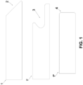
- Figure 1 shows a first mainly flat panel 1 provided with an undercut edge 2, a second mainly flat panel 1' provided with a Jpull edge 3, and a third mainly flat panel 1" provided with a radius edge 4.
- Said Jpull edges are e.g. used in kitchen cabinet doors, as they allow to open said doors while their external surface is free of handles or doorknobs.
- Figure 1 is illustrative only, having the aim to show the plurality of different edges that can be coated by a vacuum coating head according to the present invention. There is provided a wide variety of edges that are not shown in Figure 1 .
- Any panel is provided with two main sides and four edges, each of which must be coated.
- Panel coating typically occurs in production lines comprising a plurality of apparatuses placed in series. According to the organization of the production line characteristic of each production plant, for coating each side and edge there can be provided a specific apparatus, and between said apparatuses there is provided a turning device allowing to provide the following apparatus with the side or edge to be coated by that specific apparatus.
- the same apparatus can paint the four edges: the panel is conveyed four times inside the same apparatus.
- an apparatus according to the present invention coats the geometrically more complex edge, while one or further apparatus/es is/are provided for the coating of the geometrically less complex edges.
- the apparatuses indicated by the numeral 10 preceded by a digit indicate apparatuses according to the known art
- the apparatuses indicated by the numeral 30 preceded by a digit indicate apparatuses according to the present invention.
- the digit preceding 10 or 30 indicates the number of applications of painting product performed by the apparatus.
- a panel 1 is conveyed by a (not shown) conveying band (chain conveyor) that is narrower than the panel dimension perpendicular to the conveying direction.
- the panel is cantilevered with respect to the apparatus * 10, *30. Just one edge at a time of the panel 1 is worked during each passage inside the apparatus *10, *30; obviously, the edge undergoing coating is the one adjacent to the apparatus.
- Panels 1 can be manually uploaded/downloaded in/from the apparatus *10, *30 by a human operator, or loading/unloading can occur automatically using known conveyors.
- apparatuses * 10, *30 are provided with an aligner pushing the panel 1 against a reference stop.
- the same apparatus *10, *30 can be used to coat also the other edges of panels 1, one at a time.
- the bold arrows show the conveying direction of the panel 1, whose edges must be coated.
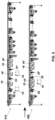
- Figure 2 shows a known art apparatus 410 currently produced by the applicant, in a top view.
- the known art apparatus 410 comprises:
- Figure 3 shows an apparatus 430 according to the present invention, in top view.
- the apparatus 430 according to the present invention comprises:
- the apparatus 430 according to the present invention is shorter than the known art apparatus 410.
- Figure 4 compares a known art apparatus 210 provided with two coating heads 13, 13' and an apparatus 430 applying four layers of painting product according to the present invention.
- the portions concerning the coating are indicated.
- the portions downstream the coating portion are variable according to the panels to be coated.
- the downstream portion comprising the sundry sanding groups is purposefully identical in the two apparatuses, so as to facilitate the comparison between the known art apparatus 210 and the apparatus 430 according to the present invention.
- the panel is conveyed just once inside the apparatus.
- the same panel must be conveyed twice inside the apparatus 210: the apparatus is shorter, but the coating cycle must be repeated in order to obtain a qualitative result comparable to that obtainable with just one cycle in the apparatus 430 according to the present invention.
- Figure 5 compares a known art apparatus 310 provided with three coating heads 13, 13', 13" and an apparatus 430 applying four layers of painting product according to the present invention.
- the portions concerning the coating are indicated.
- the portions downstream the coating portion are variable according to the panels to be coated.
- the downstream portion comprising the sundry sanding groups is purposefully identical in the two apparatuses, so as to facilitate the comparison between the known art apparatus 310 and the apparatus 430 according to the present invention.
- the result obtained with the apparatus 310 and the apparatus 430 is not equivalent: in fact, with the apparatus 310 three layers of painting product are applied, while with the apparatus 430 four layers of painting product are applied. With a comparable length of the two apparatuses, the qualitative result is better with the apparatus 430. Moreover, with the apparatus 430 a vacuum tower is dispensed with.
- Figure 6 compares a known art apparatus 510 provided with five coating heads 13, 13', 13", 13"', 13"" according to the known art and an apparatus 530 applying four layers of painting product according to the present invention.
- the portions concerning the coating are indicated.
- the portions downstream the coating portion are variable according to the panels to be coated.
- the downstream portion comprising the sundry sanding groups is purposefully identical in the two apparatuses, so as to facilitate the comparison between the known art apparatus 510 and the apparatus 530 according to the present invention.
- FIG 6 shows a particular embodiment, wherein each vacuum coating head 23, 23' of the apparatus 30 is supplied by a respective vacuum tower 14, 14'.
- a vacuum tower 14 can supply two and even three vacuum coating heads 23, 23'.
- the first vacuum tower supplies a primer to the first vacuum coating head 23, while the second vacuum tower 14' supplies a painting product to the second vacuum coating head 23'.
- Figure 7 compares a known art apparatus 610 provided with six coating heads 13, 13', 13", 13'", 13"", 13 ⁇ ′ according to the known art and an apparatus 630 applying six layers of painting product according to the present invention.
- the portions concerning the coating are indicated.
- the portions downstream the coating portion are variable according to the panels to be coated.
- the downstream portion comprising the sundry sanding groups is purposefully identical in the two apparatuses, so as to facilitate the comparison between the known art apparatus 610 and the apparatus 630 according to the present invention.
- the second gelling step is performed by just one gelling group 15" followed by a third application of painting product performed by a third vacuum coating head 23". Finally, the last gelling/drying step is performed by a gelling/drying group 16, 16'.
- this apparatus is used for finishing of a particularly high quality.
- Figures 2, 3 , 6 and 7 allow to visually appreciate the reduction in the length of the apparatuses according to the present invention with respect to the known art apparatuses, the number of applications of painting product being the same. Said reduction in length can indicatively range 1 to 5 metres.
- the method according to the present invention comprises the following steps performed by an apparatus 430:
- the method according to the present invention comprises the following steps performed by an apparatus 630:
- the gallium lamp in the gelling group 15, 15' are set on 80 W/cm
- the gallium lamps in the gelling group 16 are set on 60-65 W/cm
- the mercury lamps in the drying group 16' are set on 120-150 W/cm.
- LED lamps ranging 8 W up to 20 W can be used. In this case, indicatively, for gelling steps 20 W LED lamps are set on 10-12 W/cm 2 , while for drying steps 20 W LED lamps are set on 18-20 W/cm 2 .
- the sanding group 22 is preferably provided in the form of a sanding wheel with a cloth Trizact ⁇ 3M ® , comprising a ceramic abrasive material supported by a polyester cloth.
- the sanding performed by the sanding group 22, placed between the application of the first two layers of painting product applied by the first vacuum coating head 23, and the application of the second two layers of painting product applied by the second vacuum head 23', allows to obtain a coated surface that is smoother and more even. Consequently, with the following applications of painting product an even better result is obtained.
- the final sanding performed with the sanding groups downstream the second vacuum coating head 23' allows to obtain a perfectly smooth surface.
- FIGS 8A, 8B show a vacuum head 23 that is advantageously comprised inside the apparatuses *30 according to the present invention. Said vacuum head allows to maximize the advantages applying the method according to the present invention.
- Said vacuum coating head 23 comprises:
- a screed 53 protruding with respect to the profile of the vacuum coating head for a length ranging 0,1 to 0,5 mm. This minimal protrusion, difficult to be appreciated in the Figures, allows the screed 53 to perform two actions:
- the vacuum coating heads used to be produced in the form of coating heads made of a plurality of plates as in this way obtaining cavities in solid pieces used to be easier. It is known obtaining said plates in metallic materials, in a plastic material, or even in a wooden material (phenolic wood).
- the vacuum head 23 according to the present invention can be produced in a single solid piece, produced in plastic material, e.g. in epoxy resin, or in a metallic material, e.g. aluminium or stainless steel, provided with suitable characteristics.
- the vacuum coating head 23, provided with two dispensing nozzles 51, 55 in fact applies two layers of painting product with respect to the vacuum known art coating head 13, which is provided with just one dispensing nozzle.
- the application of painting product by the second dispensing nozzle 55 on the first layer of painting product dispensed by the first dispensing nozzle 51 is in fact a wet-on-wet application, as the gelling group 15 is placed downstream each vacuum coating head 23.
Landscapes
- Engineering & Computer Science (AREA)
- Life Sciences & Earth Sciences (AREA)
- Wood Science & Technology (AREA)
- Physics & Mathematics (AREA)
- Plasma & Fusion (AREA)
- Mechanical Engineering (AREA)
- Application Of Or Painting With Fluid Materials (AREA)
Abstract
1. sanding of the rough edge;
2. first application of painting product to the edge;
3. first gelling;
4. post-gelling sanding of the edge;
5. second application of said painting product to the edge;
6. drying;
7. final post-drying sanding;
characterized in that
- in steps 2 and 5, the application of said painting product to the panel edge occurs through two layers of painting product applied in a wet-on-wet close succession using only one vacuum head (23, 23') applying two layers of painting product in each step;
- in step 4, the post-gelling sanding occurs on a layer of painting product that underwent gelation only.
Description
- The present invention relates to a method for coating rigid panels made of wood or other materials, like e.g. MDF (Medium Density Fibreboard) wood, fibreboard or other wooden materials, with liquid painting products. In particular, the present invention relates to a method comprising a plurality of successive steps for applying a fluid coating substance, like a painting product, on an external edge of a panel made of a rigid material with different shapes.
- Mainly flat panel means a panel wherein two out of three dimensions are much wider than the third dimensions. Typically, the measures of such panels range 100x300x18 mm to 1250x2400x30 mm.
- As known, such panels are coated in order to provide them with an aesthetic effect. E.g., in the case of fibreboard panels, i.e. a low-cost material, side coatings are applied so as to cover their uneven surface.
- In a known way in the art, such coating is applied through a coating device making use of suction, of the kind comprising a coating head (vacuum coating head) provided with a chamber fed with a liquid painting product to be applied on the wooden panels.
- The chamber of each vacuum coating head typically is provided with an opening shaped according to the shape of the transversal section of the panels to be coated. In particular, the opening is counter-shaped to the transversal profile of the panel edge. The opening is placed aligned along a conveying direction of the panel, corresponding to the longitudinal profile of the edge to be coated.
- During the conveying of said panel, the panel edge is conveyed near said opening, which supplies the painting product through an output slot for the liquid painting product. Said slot defines a nozzle that at least partially follows the transversal perimeter of the panel edge, at a constant distance so as to lap the whole surface to be coated.
- The dispensing slot is adjacent to at least one suction opening, provided for suctioning the liquid painting product, so as to prevent that said painting product can leak out from the coating head.
- In this way, the excess liquid painting product, which is not applied on the edge of the conveying panel, is recovered by the suctioning opening and channelled to a reservoir of the liquid painting product.
- By adjusting: a) the viscosity of the liquid painting product; b) the flow rate through the dispensing slot; c) the conveying speed of said panel; d) the degree of vacuum provided by the suction recovering excess painting product, the thickness of the painting product applied on said panel is determined.
- In addition to the unevenness typical of wooden surfaces, it is known that the use of vacuum suction tends to raise wood fibres, which protrude outside the film of the applied painting product. In order to avoid this drawback, two strategies can be used: a) using a very thick layer of painting product, so as to cover the raised wood fibre; or alternatively b) sanding the coated edge. The first strategy leads to a high and costly consumption of painting product; the second strategy leads to a more complex coating machine, provided with a greater length due to the presence of many sanding groups.
- The applicant has been producing machines provided with one or more vacuum coating heads for suction coating for a long time, one of which is e.g. described in
EP3315210A1 . Said application describes a vacuum coating head comprising a body, at least a top form and at least a lower form. - In the art, there are known also vacuum coating heads made of a plurality of adjacent plates, e.g. from
IT102009901728856 of Makor - In the art, it is known that in edge coating the greatest difficulties are coating Jpull or undercut edges (see
Figure 1 ). In particular, the more complex the surface, the higher the number of sanding groups. - In the art it is known that in order to obtain panels provided with edges having a suitable quality, coating cycles comprising many successive steps must be performed. The traditional coating cycle today performed by the applicant comprises the following steps:
- 1. sanding of the rough edge;
- 2. first coating of the edge;
- 3. first gelling;
- 4. second coating of the edge;
- 5. second gelling;
- 6. third coating of the edge;
- 7. third gelling;
- 8. fourth coating of the edge;
- 9. drying;
- 10. final sanding (using at least four band sanding groups + two sanding wheels).
- A second coating cycle for a finishing of superior quality comprises the following steps:
- 1. sanding of the rough edge;
- 2. first coating of the edge;
- 3. first gelling;
- 4. second coating of the edge;
- 5. drying;
- 6. sanding (using at least four band sanding groups + two sanding wheels)
- 7. third coating of the edge;
- 8. third gelling;
- 9. fourth coating of the edge;
- 10. fourth gelling;
- 11. fifth coating of the edge;
- 12. fifth gelling;
- 13. sixth coating of the edge;
- 14. drying;
- 15. final sanding (using at least four band sanding groups + two sanding wheels).
- The number of painting product applications can range one to six (consequently the apparatus comprises one to six vacuum coating heads), depending on the desired quality of the final product.
-
US20210121912A1 of Louisiana Pacific Corp describes a method for producing engineered-wood fence pickets. The edge-sanding process produces a smooth side surface on the edges, significantly reducing the number of loose fibres and/or strands, and fills in and/or reduces void spaces. The painting of the pickets is performed through spraying. -
US3967581A of Edward Irvin Zirbel describes an apparatus for finishing the edge of particleboard, plywood and the like. The finishing is performed by extruding a fast-drying material. -
DE102014107492 of MHF GMBH describes a method for smoothing the edges of workpieces which have at least one porous layer. Said method comprises the following steps: conveying the workpieces on a conveyor in a direction parallel to the edge to be smoothed; allowing a continuous carrier strip to pass over deflection rollers at a speed which is synchronous to the conveying speed of the workpieces, such that a contact section of the carrier strip rests on a section of the edge of at least one workpiece to be smoothed over a certain length; applying, upstream of the contact section, a curable filler onto the carrier strip; transferring the filler on the contact section onto the edge such that it forms a continuous layer of predetermined thickness; and allowing the filler to cure, once the carrier strip has been removed, until the continuous layer forms a smooth, solid surface. -
DE10100518 of Joseph Schiele OHG describes a device for coating the lateral edge faces of elongate work pieces with a liquid coating medium. The inventive device comprises an adjustable coating head with a coating slot that extends in the direction of transport of the work piece. Said coating head applies the liquid coating medium through just one nozzle at a time. - ITFI20090093 of Makor SRL describes a coating vacuum head for panels comprising a screeding organ placed downstream the organ supplying a coating product, in order to uniformly distribute said coating product and to remove from said panel a portion of the coating medium in excess.
- In the art, it is known using painting products comprising photopolymerizing agents activated by ultraviolet (UV) radiations. Such painting products comprise a plurality of monomers that, once activated by UV radiations emitted by lamps of suitable wavelength, are involved in a photopolymerizing process leading to the formation of a polymer network. The quantity of radiation administered to the film of painting product applied on the panel can lead to an incomplete polymerization (gelling) or to a complete polymerization, wherein all the monomers contained in the painting product are concatenated in a polymer network (drying).
- The gelling/drying of the painting product can be described in terms of percentage of monomers that react after undergoing UV radiation: indicatively, if complete drying corresponds to about 100% of polymerized monomers, gelling corresponds to about 50% of polymerized monomers after the action of UV radiation. It is intuitive that sanding must occur on a painting product sufficiently polymerized so that it does not stick to sanding groups.
- In terms of adjusting the apparatus for coating edges, the percentage of polymerization of the applied painting product depends also on the power of the lamp used for the gelling step. Again indicatively, the polymerizing lamps emitting UV radiations for gelling are set on about 80 W/cm, while for drying the polymerizing lamps are set on about 150 W/cm. It is also worth mentioning that gelling is preferably performed using gallium lamps, while drying is preferably performed using mercury lamps.
- The known art coating method is performed through known art apparatuses, which substantially are apparatuses having a given length, in that each of the above-described ten or fifteen steps is performed by a group (sanding group, coating group, gelling group, drying group) placed in series with respect to the preceding and following group. The working of panel edges occurs in passing. Typically, a known art apparatus is 10 to 30 metres long. The length of the apparatus is directly proportional to the number of groups provided in the apparatus, which in turn is directly proportional to the desired quality of the finished panel.
- Aim of the present invention is providing a method and an apparatus to perform such method for vacuum coating making use of one or more vacuum coating heads, which is cheaper to perform and that allows to obtain better results in terms of the quality of the coated panel.
- This object is achieved by a method and an apparatus having the features of the independent claims. Advantageous embodiments and refinements are specified in claims dependent thereon.
- The method according to the present invention provides the following successive steps:
- 1. sanding of the rough edge;
- 2. first application of painting product to the edge;
- 3. first gelling;
- 4. post-gelling sanding of the edge;
- 5. second application of painting product to the edge;
- 6. drying;
- 7. post-drying sanding.
- In an alternative embodiment, for a superior quality of the coated edge, the successive steps are:
- 1. sanding of the rough edge;
- 2. first application of painting product to the edge;
- 3. first gelling;
- 4. post-gelling sanding of the edge;
- 5. second application of painting product to the edge;
- 6. second gelling;
- 7. third application of painting product to the edge;
- 8. drying;
- 9. post-drying sanding.
- Substantially, the novelty of the present method with respect to the known art lies in the following two features:
- the application of the painting product occurs through the application of two layers of painting product in a close succession, in a wet-on-wet mode;
- the first sanding after the first application of painting product is performed on the painted product which underwent gelation only, wherein a significant percentage of monomers is not polymerized; obviously, the degree of polymerization must be suitable so that the coated layer can be sanded.
- By performing a sanding step after the first application of coating followed by gelling the following results are obtained:
- a smooth surface, because the fibre of the wooden material protruding from the film of painting product is cut (sanded);
- the following applications of painting products are much smoother:
the orange peel effect is nearly completely removed, and therefore the final sanding of the panel is easier and requires a lesser number of sanding groups. - The new coating cycle allows to obtain many advantages:
- If instead of gelling it, the applied coating were dried, as oftentimes one must do, the edge should be sanded over its whole coated surface using many sanding groups; while with gelation, only the portion of the edge wherein the wooden fibre is raised is sanded. The sanding on the gelled portion is easier, in that a lesser number of sanding groups are necessary in order to reach all the surfaces of a complex edge like e.g. a Jpull edge: just a sanding wheel or a band are sufficient;
- The following applications of painting products are eased by the lack of protruding wooden fibres; the coating is more efficient, and finally this allows a reduction in the number of steps and of the final thickness of the layers of applied painting product;
- The quantity of energy is markedly reduced (of about 20%, up to 35% according to apparatus configuration).
- Experimentally, it was shown that by using a vacuum coating head applying two layers of painting product each according to the new method, the same qualitative result as using two known art vacuum coating heads is obtained.
- Experimentally, it was shown that by using three vacuum coating heads applying two layers of painting product each according to the new method, the same qualitative result as using six known art vacuum coating heads is obtained.
- Overall, the number of coating heads is reduced, and therefore there is a saving in the number of elements used both for applying and drying the painting product, which allows to reduce the overall length of the apparatus. Experimentally, it was shown that the quality of the finished panel being the same, the new method for applying a painting product allows to produce apparatuses that are 1-5 metres shorter with respect to the currently used apparatuses performing the known art coating cycle, with a significant saving in the required industrial space.
- It is worth noting that the number of sanding groups placed downstream the coating groups, affecting the overall length of the apparatus, depends on the geometrical shape of the edge to be sanded and on the quality of the desired finishing.
- All this translates into an apparatus that provides a coating of outstanding quality but much cheaper to produce and of shorter length, without considering the savings in terms of energy consumption during the functioning of the apparatus.
- Further advantages and properties of the present invention are disclosed in the following description, in which exemplary embodiments of the present invention are explained in detail based on the drawings:
- Figure 1
- Examples of panels provided with different edges: undercut edge, Jpull edge, radius edge, in transversal section;
- Figure 2
- Known art apparatus provided with four coating heads, top view;
- Figure 3
- Apparatus according to the present invention configured for providing four painting product applications, top view;
- Figure 4
- Known art apparatus provided with two coating heads and apparatus according to the present invention configured for providing four painting product applications, top view;
- Figure 5
- Known art apparatus provided with three coating heads and apparatus according to the present invention configured for providing four painting product applications, top view;
- Figure 6
- Known art apparatus provided with five coating heads and apparatus according to the present invention configured for providing four painting product applications, top view;
- Figure 7
- Known art apparatus provided with six coating heads and apparatus according to the present invention configured for providing six painting product applications, top view;
- Figure 8A, 8B
- Vacuum coating head according to the present invention in front and axonometric view.
- For the sake of clarity, in this Description a vacuum tower, indicated in this Description with the numeral 14, means a unit providing both the painting product and the vacuum to the vacuum head.
-
Figure 1 shows a first mainlyflat panel 1 provided with an undercut edge 2, a second mainly flat panel 1' provided with aJpull edge 3, and a third mainlyflat panel 1" provided with a radius edge 4. Said Jpull edges are e.g. used in kitchen cabinet doors, as they allow to open said doors while their external surface is free of handles or doorknobs.Figure 1 is illustrative only, having the aim to show the plurality of different edges that can be coated by a vacuum coating head according to the present invention. There is provided a wide variety of edges that are not shown inFigure 1 . - Any panel is provided with two main sides and four edges, each of which must be coated. Panel coating typically occurs in production lines comprising a plurality of apparatuses placed in series. According to the organization of the production line characteristic of each production plant, for coating each side and edge there can be provided a specific apparatus, and between said apparatuses there is provided a turning device allowing to provide the following apparatus with the side or edge to be coated by that specific apparatus. Alternatively, the same apparatus can paint the four edges: the panel is conveyed four times inside the same apparatus. Alternatively, an apparatus according to the present invention coats the geometrically more complex edge, while one or further apparatus/es is/are provided for the coating of the geometrically less complex edges.
- In the art, there are known apparatuses provided with variable numbers of post-coating sanding groups. The more geometrically complex the
edge 2, 3, 4, the higher the number of sanding groups provided in the apparatus in order to have a perfectly coated panel, in that each of them is adjusted to sand just one portion of said edge. It is worth noting that, according to the kind of batch produced in a given moment, in an apparatus provided with a high number of sanding groups, some sanding groups might be inactive during the production of that specific batch. - In
Figure 2 and 3 a knownart apparatus 410 with four coating heads according to the known art and anapparatus 430 applying four layers of painting product according to the present invention are compared. This is just one of many possible configurations, some of which are shown inFigures 4- 7. - It is worth mentioning that in the following Description, the apparatuses indicated by the numeral 10 preceded by a digit indicate apparatuses according to the known art, while the apparatuses indicated by the numeral 30 preceded by a digit indicate apparatuses according to the present invention. The digit preceding 10 or 30 indicates the number of applications of painting product performed by the apparatus.
- Both in the known art apparatuses *10 and in the apparatuses *30 according to the known art, a
panel 1 is conveyed by a (not shown) conveying band (chain conveyor) that is narrower than the panel dimension perpendicular to the conveying direction. The panel is cantilevered with respect to the apparatus * 10, *30. Just one edge at a time of thepanel 1 is worked during each passage inside the apparatus *10, *30; obviously, the edge undergoing coating is the one adjacent to the apparatus.Panels 1 can be manually uploaded/downloaded in/from the apparatus *10, *30 by a human operator, or loading/unloading can occur automatically using known conveyors. In a known way, apparatuses * 10, *30 are provided with an aligner pushing thepanel 1 against a reference stop. Optionally the same apparatus *10, *30 can be used to coat also the other edges ofpanels 1, one at a time. - As explained above, the length of the apparatus varies proportionally to the numerousness of groups. In this first comparison (
Figure 2 and 3 ) a known art apparatus provided with four coating head according to the known art and an apparatus applying four layers of painting product according to the present invention are compared. The number of sanding groups placed downstream the drying group is the same, so as to show a meaningful comparison in terms of apparatus length between the known art apparatus and an apparatus according to the present invention. - The bold arrows show the conveying direction of the
panel 1, whose edges must be coated. -
Figure 2 shows a knownart apparatus 410 currently produced by the applicant, in a top view. - The known
art apparatus 410 comprises: - a
sanding group 11 for a coarse pre-coating sanding; - a sanding group 12 (here in the shape of a sanding wheel) for a finer sanding;
- four vacuum coating heads 13, 13', 13", 13''';
- two
vacuum towers 14, 14' each vacuum tower supplies a painting product to two coating heads:
in particular, thevacuum tower 14 supplies said painting product to the vacuum heads 13, 13', while the vacuum tower 14' supplies said painting product to the vacuum heads 13", 13"'; - three gelling
groups - two drying
groups 16, 16' said drying groups comprise one or more mercury and/or gallium lamps which completely polymerize the monomers of the painting product; - a
belt sanding group 17; - four sanding
groups - three sanding
groups - two
corner sanding groups 20, 20', for sanding the head and the tail ofpanel 1, respectively; - a
sanding group 21 for the final sanding: this is a sanding group provided with a belt with a particularly fine grain. -
Figure 3 shows anapparatus 430 according to the present invention, in top view. - The
apparatus 430 according to the present invention comprises: - a
sanding group 11 for a coarse pre-coating sanding; - a sanding group 12 (here in the shape of a sanding wheel) for a finer sanding;
- two vacuum coating heads 23, 23';
- one
vacuum tower 14; - two gelling
groups 15, 15'; - a
sanding group 22 placed immediately downstream thefirst gelling group 15, 15'; - two drying
groups 16, 16'; - a
belt sanding group 17; - four sanding
groups - three sanding
groups - two
corner sanding groups 20, 20', for sanding the head and the tail ofpanel 1, respectively; - a
sanding group 21 for the final sanding: this is a sanding group provided with a belt with a particularly fine grain. - At a glance, it can be observed that the
apparatus 430 according to the present invention is shorter than the knownart apparatus 410. -
Figure 4 compares a knownart apparatus 210 provided with two coating heads 13, 13' and anapparatus 430 applying four layers of painting product according to the present invention. In the Figure, just the portions concerning the coating are indicated. As explained above, the portions downstream the coating portion are variable according to the panels to be coated. The downstream portion comprising the sundry sanding groups is purposefully identical in the two apparatuses, so as to facilitate the comparison between the knownart apparatus 210 and theapparatus 430 according to the present invention. - In the case of a panel requiring four applications of painting product, with the
apparatus 430 according to the present invention, the panel is conveyed just once inside the apparatus. Instead, with the knownart apparatus 210, the same panel must be conveyed twice inside the apparatus 210: the apparatus is shorter, but the coating cycle must be repeated in order to obtain a qualitative result comparable to that obtainable with just one cycle in theapparatus 430 according to the present invention. -
Figure 5 compares a knownart apparatus 310 provided with three coating heads 13, 13', 13" and anapparatus 430 applying four layers of painting product according to the present invention. In the Figure, just the portions concerning the coating are indicated. As explained above, the portions downstream the coating portion are variable according to the panels to be coated. The downstream portion comprising the sundry sanding groups is purposefully identical in the two apparatuses, so as to facilitate the comparison between the knownart apparatus 310 and theapparatus 430 according to the present invention. - The result obtained with the
apparatus 310 and theapparatus 430 is not equivalent: in fact, with theapparatus 310 three layers of painting product are applied, while with theapparatus 430 four layers of painting product are applied. With a comparable length of the two apparatuses, the qualitative result is better with theapparatus 430. Moreover, with the apparatus 430 a vacuum tower is dispensed with. -
Figure 6 compares a knownart apparatus 510 provided with five coating heads 13, 13', 13", 13"', 13"" according to the known art and anapparatus 530 applying four layers of painting product according to the present invention. In the Figure, just the portions concerning the coating are indicated. As explained above, the portions downstream the coating portion are variable according to the panels to be coated. The downstream portion comprising the sundry sanding groups is purposefully identical in the two apparatuses, so as to facilitate the comparison between the knownart apparatus 510 and theapparatus 530 according to the present invention. -
Figure 6 shows a particular embodiment, wherein eachvacuum coating head 23, 23' of the apparatus 30 is supplied by arespective vacuum tower 14, 14'. As explained above, avacuum tower 14 can supply two and even three vacuum coating heads 23, 23'. In this case, though, there are provided two distinct vacuum towers 14, 14': the first vacuum tower supplies a primer to the firstvacuum coating head 23, while the second vacuum tower 14' supplies a painting product to the second vacuum coating head 23'. -
Figure 7 compares a knownart apparatus 610 provided with six coating heads 13, 13', 13", 13'", 13"", 13ʺʺ′ according to the known art and anapparatus 630 applying six layers of painting product according to the present invention. In the Figure, just the portions concerning the coating are indicated. As explained above, the portions downstream the coating portion are variable according to the panels to be coated. The downstream portion comprising the sundry sanding groups is purposefully identical in the two apparatuses, so as to facilitate the comparison between the knownart apparatus 610 and theapparatus 630 according to the present invention. - In the case of the
apparatus 630 applying six layers of painting product, the second gelling step is performed by just one gellinggroup 15" followed by a third application of painting product performed by a thirdvacuum coating head 23". Finally, the last gelling/drying step is performed by a gelling/drying group 16, 16'. Of course, this apparatus is used for finishing of a particularly high quality. -
Figures 2, 3 ,6 and7 allow to visually appreciate the reduction in the length of the apparatuses according to the present invention with respect to the known art apparatuses, the number of applications of painting product being the same. Said reduction in length can indicatively range 1 to 5 metres. - The method according to the present invention comprises the following steps performed by an apparatus 430:
- 1. sanding of the rough edge performed by the sanding
groups vacuum head 23; - 2. first application of painting product to the edge performed by the first
vacuum coating head 23; - 3. gelling
performed by two gellinggroups 15, 15', preferably comprising one or more gallium lamps; - 4. post-gelling sanding of the edge performed with sanding wheels, bands or any other sanding system by the
sanding group 22; - 5. second application of painting product to the edge performed by the second vacuum coating head 23'; the first
vacuum coating head 23 and the second coating head 23' are preferably supplied by just onevacuum tower 14; - 6. drying
performed by thedrying group 16, 16', preferably comprising one or more mercury lamps; - 7. post-drying final sanding performed by a number of
sanding groups - In an alternative embodiment, suitable for a superior quality of the coated edge, the method according to the present invention comprises the following steps performed by an apparatus 630:
- 1. sanding of the rough edge performed by the sanding
groups vacuum head 23; - 2. first application of painting product to the edge performed by the first
vacuum coating head 23; - 3. first gelling
performed by at least one, preferably two gellinggroups 15, 15'; - 4. post-gelling sanding of the edge performed with sanding wheels, bands or any other sanding system by the
sanding group 22; - 5. second application of painting product to the edge performed by the second vacuum coating head 23';
- 6. second gelling
performed by at least one gellinggroups 15"; - 7. third application of painting product to the edge performed by the third
vacuum coating head 23"; - 8. drying
performed by thedrying group 16, 16'; - 9. post-drying final sanding performed by a number of
sanding groups - It is worth mentioning that in the apparatuses *30 according to the present invention, the gallium lamp in the
gelling group 15, 15' are set on 80 W/cm, the gallium lamps in thegelling group 16 are set on 60-65 W/cm, while the mercury lamps in the drying group 16' are set on 120-150 W/cm. These power levels, too, contribute to the reduced energy consumption with respect to the known art apparatuses. - Alternatively, in lieu of the gallium and mercury lamps, LED lamps ranging 8 W up to 20 W can be used. In this case, indicatively, for gelling steps 20 W LED lamps are set on 10-12 W/cm2, while for drying steps 20 W LED lamps are set on 18-20 W/cm2.
- The
sanding group 22 is preferably provided in the form of a sanding wheel with a cloth Trizact© 3M®, comprising a ceramic abrasive material supported by a polyester cloth. - The sanding performed by the
sanding group 22, placed between the application of the first two layers of painting product applied by the firstvacuum coating head 23, and the application of the second two layers of painting product applied by the second vacuum head 23', allows to obtain a coated surface that is smoother and more even. Consequently, with the following applications of painting product an even better result is obtained. The final sanding performed with the sanding groups downstream the second vacuum coating head 23' allows to obtain a perfectly smooth surface. -
Figures 8A, 8B show avacuum head 23 that is advantageously comprised inside the apparatuses *30 according to the present invention. Said vacuum head allows to maximize the advantages applying the method according to the present invention. - Said
vacuum coating head 23 comprises: - a pair of
bores 50 for fixing said head to a support allowing to connect said head to theapparatus 430; - a
first dispensing nozzle 51 for dispensing a painting product; - a
first suction nozzle 52 for suctioning said painting product; - an
optional screed 53; - a
second dispensing nozzle 55 for dispensing said painting product; - a
second suction nozzle 56 for suctioning said painting product. - In the preferred embodiment, between the
first suction nozzle 52 for suctioning a painting product and thesecond dispensing nozzle 55 for dispensing a painting product, there is provided ascreed 53 protruding with respect to the profile of the vacuum coating head for a length ranging 0,1 to 0,5 mm. This minimal protrusion, difficult to be appreciated in the Figures, allows thescreed 53 to perform two actions: - pressing the applied painting product inside wood pores;
- pressing the wooden fibres raised by the suction generated by the
first suction nozzle 52. - Here is worth noting that up to the introduction of 3D printing the vacuum coating heads used to be produced in the form of coating heads made of a plurality of plates, as in this way obtaining cavities in solid pieces used to be easier. It is known obtaining said plates in metallic materials, in a plastic material, or even in a wooden material (phenolic wood).
- Nowadays, with 3D printing, pieces provided with internal cavities can be produced through additive manufacturing; therefore, the
vacuum head 23 according to the present invention can be produced in a single solid piece, produced in plastic material, e.g. in epoxy resin, or in a metallic material, e.g. aluminium or stainless steel, provided with suitable characteristics. - It is worth noting that the
vacuum coating head 23, provided with two dispensingnozzles art coating head 13, which is provided with just one dispensing nozzle. The application of painting product by thesecond dispensing nozzle 55 on the first layer of painting product dispensed by thefirst dispensing nozzle 51 is in fact a wet-on-wet application, as the gellinggroup 15 is placed downstream eachvacuum coating head 23. - The skilled man has the entrenched prejudice that by gelling the applied layer before applying the second layer of painting product a better result will be obtained, due to the better adhesion of the successive layer of painting product on a dried or at least gelled layer. Surprisingly, it was observed that the presence of the screed compensates for the lack of gelation, and it presses the wood fibres raised by the
first suction nozzle 52. This overall allows to provide a higher quantity of painting product on thepanel 1 with respect to the usual coating method (application of painting product - gelation - successive application of painting product). - 1
- panel
- 2
- undercut edge
- 3
- Jpull edge
- 4
- radius edge
- 11
- coarse sanding group
- 12
- sanding group
- 13
- vacuum coating head
- 14
- vacuum tower
- 15
- gelling group
- 16
- drying group
- 17
- band sanding group
- 18
- coarse sanding group
- 19
- fine sanding group
- 20
- corner sanding group
- 21
- final sanding group
- 22
- sanding group
- 23
- vacuum coating head
- 50
- bore
- 51
- first dispensing nozzle
- 52
- first suction nozzle
- 53
- screed
- 55
- second dispensing nozzle
- 56
- second suction nozzle
- 57
- bore
- 58
- bore
- 210
- known art apparatus with two coating heads
- 310
- known art apparatus with three coating heads
- 410
- known art apparatus with four coating heads
- 430
- apparatus according to the present invention with four applications of painting product
- 510
- known art apparatus with five coating heads
- 530
- apparatus according to the present invention with four applications of painting product
- 610
- known art apparatus with six coating heads
- 630
- apparatus according to the present invention with six applications of painting product
Claims (9)
- Method for applying a painting product, preferably an UV painting product, to an edge of wooden panels (1) through an apparatus comprising pre-coating sanding groups (11, 12) and post-drying sanding groups (17, 18, 19, 20, 21), at least a painting group provided in the form of a vacuum coating head (23) supplied with both said painting product and vacuum by a vacuum tower (14), at least a gelling group (15), at least a drying group (16) placed in series comprising the following successive steps:1. sanding of the rough edge;2. first application of painting product to the edge;3. first gelling;4. post-gelling sanding of the edge;5. second application of said painting product to the edge;6. drying;7. final post-drying sanding;characterized in that- in each one of steps 2 and 5, the application of said painting product to the panel edge occurs through two layers of painting product applied in a wet-on-wet close succession;- in step 4, the post-gelling sanding occurs on a layer of painting product that underwent gelation only.
- Method for applying a painting product, preferably an UV painting product, to an edge of wooden panels (1) through a vacuum coating head (23) according to claim 1, wherein for a superior quality of the finished panel a further application of painting product is provided, according to the following successive steps:1. sanding of the rough edge;2. first application of painting product to the edge;3. first gelling;4. post-gelling sanding of the edge;5. second application of painting product to the edge;6. second gelling;7. third application of painting product to the edge;8. drying;9. post-drying sanding.
- Method for applying a painting product, preferably an UV painting product, to an edge of wooden panels (1) through a vacuum coating head (23) according to claim 1 or 2, wherein said wet-on-wet applications of painting product occurs through a vacuum coating head (23) provided at least with two nozzles (51, 55) for applying said painting product.
- Apparatus (430, 530, 630) for performing the method according to claims 1-3 for applying a painting product, preferably an UV painting product, to an edge of wooden panels (1), said apparatus comprising in that order:1. first sanding groups (11, 12) placed upstream the first vacuum head (23);2. first coating head (23) for applying a painting product to the panel edge, applying two wet on wet layers of the painting product in a close succession;3. at least one, preferably two gelling groups (15, 15'), preferably comprising one or more gallium lamps;4. post-gelling sanding group (22) of the edge, preferably in the form of sanding wheels, bands;5. second vacuum coating head (23') for applying a painting product to the edge, applying two wet on wet layers of the painting product in a close succession:6. at least a drying group (16, 16');7. post-drying final sanding groups (17, 18, 19, 20, 21) in a number proportional to the desired quality of the finished panel.
- Apparatus (630) for applying a painting product, preferably an UV painting product, to an edge of wooden panels (1) according to claim 4 comprising in that order:1. first sanding groups (11, 12) placed upstream the first vacuum head (23);2. first vacuum coating head (23) for applying a painting product to the panel edge, applying two wet on wet layers of the painting product in a close succession;3. at least one first, preferably two gelling groups (15, 15');4. post-gelling sanding group (22), preferably in the form of sanding wheels, bands;5. second vacuum coating head (23') for applying a painting product to the panel edge, applying two wet on wet layers of the painting product in a close succession;6. at least one second gelling group (15");7. third vacuum coating head (23") for applying a painting product to the panel edge, applying two wet on wet layers of the painting product in a close succession;8. at least a drying group (16, 16');9. post-drying final sanding groups (17, 18, 19, 20, 21) in a number proportional to the desired quality of the finished panel.
- Apparatus (430, 530, 630) according to claim 4 or 5, wherein each vacuum tower (14) supplies one, preferably two or three vacuum coating heads (23, 23', 23").
- Apparatus (430, 530, 630) according to one or more of claims 4-6, wherein when the painting products to be applied to an edge are more than one, there is provided a number of vacuum towers (14) equal to the number of painting products used in the coating process.
- Apparatus (430, 530, 630) according to one or more of claims 4-7, wherein the lamps in said gelling groups (15) are gallium lamps, preferably set at 60-80 W/cm, or LED lamps preferably set at 10-12 W/cm2.
- Apparatus (430, 530, 630) according to one or more of claims 4-7, wherein the lamps in said drying groups (16, 16') are gallium lamps or mercury lamps preferably set at 120-150 W/cm or alternatively LED lamps preferably set at 18-20 W/cm2.
Applications Claiming Priority (1)
| Application Number | Priority Date | Filing Date | Title |
|---|---|---|---|
| IT102022000005738A IT202200005738A1 (en) | 2022-03-23 | 2022-03-23 | METHOD FOR PAINTING PANELS USING VACUUM HEADS |
Publications (2)
| Publication Number | Publication Date |
|---|---|
| EP4249135A1 true EP4249135A1 (en) | 2023-09-27 |
| EP4249135B1 EP4249135B1 (en) | 2024-12-18 |
Family
ID=81850975
Family Applications (1)
| Application Number | Title | Priority Date | Filing Date |
|---|---|---|---|
| EP23162916.3A Active EP4249135B1 (en) | 2022-03-23 | 2023-03-20 | Method for coating panel edges through vacuum coating heads |
Country Status (3)
| Country | Link |
|---|---|
| EP (1) | EP4249135B1 (en) |
| ES (1) | ES3014966T3 (en) |
| IT (1) | IT202200005738A1 (en) |
Citations (7)
| Publication number | Priority date | Publication date | Assignee | Title |
|---|---|---|---|---|
| US3967581A (en) | 1971-07-06 | 1976-07-06 | Irvin Edward Zirbel | Apparatus for applying a coating to a workpiece edge |
| DE10100518A1 (en) | 2001-01-08 | 2002-07-11 | Josef Schiele Ohg | Edge coater |
| ITFI20090093A1 (en) * | 2009-05-05 | 2010-11-06 | Makor S R L Unipersonale | DEVICE FOR COATING RIGID PANELS WITH LIQUID PRODUCTS |
| DE102014107492A1 (en) | 2014-05-27 | 2015-12-03 | Mhf Gmbh | Method for smoothing workpiece edges |
| EP3315210A1 (en) | 2016-10-28 | 2018-05-02 | SORBINI S.r.l. | Coating head, adaptable to the outline of a panel edge or other pieces to be coated |
| US20210121912A1 (en) | 2019-10-29 | 2021-04-29 | Louisiana-Pacific Corporation | System for post-processing of engineered-wood fence pickets |
| DE102020125687A1 (en) * | 2020-10-01 | 2022-04-07 | Homag Gmbh | Device and method for coating a surface |
-
2022
- 2022-03-23 IT IT102022000005738A patent/IT202200005738A1/en unknown
-
2023
- 2023-03-20 ES ES23162916T patent/ES3014966T3/en active Active
- 2023-03-20 EP EP23162916.3A patent/EP4249135B1/en active Active
Patent Citations (7)
| Publication number | Priority date | Publication date | Assignee | Title |
|---|---|---|---|---|
| US3967581A (en) | 1971-07-06 | 1976-07-06 | Irvin Edward Zirbel | Apparatus for applying a coating to a workpiece edge |
| DE10100518A1 (en) | 2001-01-08 | 2002-07-11 | Josef Schiele Ohg | Edge coater |
| ITFI20090093A1 (en) * | 2009-05-05 | 2010-11-06 | Makor S R L Unipersonale | DEVICE FOR COATING RIGID PANELS WITH LIQUID PRODUCTS |
| DE102014107492A1 (en) | 2014-05-27 | 2015-12-03 | Mhf Gmbh | Method for smoothing workpiece edges |
| EP3315210A1 (en) | 2016-10-28 | 2018-05-02 | SORBINI S.r.l. | Coating head, adaptable to the outline of a panel edge or other pieces to be coated |
| US20210121912A1 (en) | 2019-10-29 | 2021-04-29 | Louisiana-Pacific Corporation | System for post-processing of engineered-wood fence pickets |
| DE102020125687A1 (en) * | 2020-10-01 | 2022-04-07 | Homag Gmbh | Device and method for coating a surface |
Also Published As
| Publication number | Publication date |
|---|---|
| IT202200005738A1 (en) | 2023-09-23 |
| EP4249135B1 (en) | 2024-12-18 |
| ES3014966T3 (en) | 2025-04-28 |
Similar Documents
| Publication | Publication Date | Title |
|---|---|---|
| CN102686320B (en) | For the method for coated member | |
| US3602193A (en) | Apparatus for preparing coatings with extrusions | |
| CN101495243B (en) | Coating device comprising a flowing coating material | |
| US6660086B1 (en) | Method and apparatus for extruding a coating upon a substrate surface | |
| CN108136614A (en) | Method and apparatus for coating narrow surfaces | |
| CN1104289C (en) | Method and system for painting and use thereof | |
| US11396172B2 (en) | Wood-like coating method for substrate | |
| US5770267A (en) | Method and apparatus for smoothing substrate surfaces | |
| EP4249135B1 (en) | Method for coating panel edges through vacuum coating heads | |
| EP3294507A1 (en) | Method of continuous edge processing of plates and edge processing device | |
| US7997314B2 (en) | Method and device for producing veneer and veneered parts and veneer and veneered parts | |
| CN107737690B (en) | Process and equipment for painting side surface of wood plate | |
| JP2000070845A5 (en) | ||
| CN105451893B (en) | Method and device for producing coated building panels, in particular painted building panels, and associated painted building panels | |
| US6217946B1 (en) | Method for applying polymeric diphenylmethane diisocyanate to cellulose/gypsum based substrate | |
| CA2962503C (en) | Fire barrier building product and method and system for making same | |
| KR100796274B1 (en) | Edge painter for furniture panels | |
| EP4249132B1 (en) | Vacuum coating head for coating panel edges | |
| KR200388532Y1 (en) | Edge coating apparatus for a furniture panel | |
| CN215465678U (en) | Gluing device for producing sandwich board | |
| CN219745299U (en) | Coating device for surface of sheet metal part | |
| WO2022069534A1 (en) | Device and method for coating a surface | |
| CN105127074B (en) | A kind of preprocess method of furniture part and assembly | |
| WO2024091169A1 (en) | An arrangement and a method for applying paint on an article | |
| KR100658370B1 (en) | Automatic painting device to form three-dimensional pattern |
Legal Events
| Date | Code | Title | Description |
|---|---|---|---|
| PUAI | Public reference made under article 153(3) epc to a published international application that has entered the european phase |
Free format text: ORIGINAL CODE: 0009012 |
|
| STAA | Information on the status of an ep patent application or granted ep patent |
Free format text: STATUS: THE APPLICATION HAS BEEN PUBLISHED |
|
| AK | Designated contracting states |
Kind code of ref document: A1 Designated state(s): AL AT BE BG CH CY CZ DE DK EE ES FI FR GB GR HR HU IE IS IT LI LT LU LV MC ME MK MT NL NO PL PT RO RS SE SI SK SM TR |
|
| STAA | Information on the status of an ep patent application or granted ep patent |
Free format text: STATUS: REQUEST FOR EXAMINATION WAS MADE |
|
| 17P | Request for examination filed |
Effective date: 20240315 |
|
| RBV | Designated contracting states (corrected) |
Designated state(s): AL AT BE BG CH CY CZ DE DK EE ES FI FR GB GR HR HU IE IS IT LI LT LU LV MC ME MK MT NL NO PL PT RO RS SE SI SK SM TR |
|
| GRAP | Despatch of communication of intention to grant a patent |
Free format text: ORIGINAL CODE: EPIDOSNIGR1 |
|
| STAA | Information on the status of an ep patent application or granted ep patent |
Free format text: STATUS: GRANT OF PATENT IS INTENDED |
|
| INTG | Intention to grant announced |
Effective date: 20240710 |
|
| GRAS | Grant fee paid |
Free format text: ORIGINAL CODE: EPIDOSNIGR3 |
|
| GRAA | (expected) grant |
Free format text: ORIGINAL CODE: 0009210 |
|
| STAA | Information on the status of an ep patent application or granted ep patent |
Free format text: STATUS: THE PATENT HAS BEEN GRANTED |
|
| AK | Designated contracting states |
Kind code of ref document: B1 Designated state(s): AL AT BE BG CH CY CZ DE DK EE ES FI FR GB GR HR HU IE IS IT LI LT LU LV MC ME MK MT NL NO PL PT RO RS SE SI SK SM TR |
|
| REG | Reference to a national code |
Ref country code: CH Ref legal event code: EP |
|
| REG | Reference to a national code |
Ref country code: DE Ref legal event code: R096 Ref document number: 602023001373 Country of ref document: DE |
|
| REG | Reference to a national code |
Ref country code: IE Ref legal event code: FG4D |
|
| REG | Reference to a national code |
Ref country code: LT Ref legal event code: MG9D |
|
| PG25 | Lapsed in a contracting state [announced via postgrant information from national office to epo] |
Ref country code: HR Free format text: LAPSE BECAUSE OF FAILURE TO SUBMIT A TRANSLATION OF THE DESCRIPTION OR TO PAY THE FEE WITHIN THE PRESCRIBED TIME-LIMIT Effective date: 20241218 |
|
| PG25 | Lapsed in a contracting state [announced via postgrant information from national office to epo] |
Ref country code: FI Free format text: LAPSE BECAUSE OF FAILURE TO SUBMIT A TRANSLATION OF THE DESCRIPTION OR TO PAY THE FEE WITHIN THE PRESCRIBED TIME-LIMIT Effective date: 20241218 |
|
| PG25 | Lapsed in a contracting state [announced via postgrant information from national office to epo] |
Ref country code: BG Free format text: LAPSE BECAUSE OF FAILURE TO SUBMIT A TRANSLATION OF THE DESCRIPTION OR TO PAY THE FEE WITHIN THE PRESCRIBED TIME-LIMIT Effective date: 20241218 |
|
| PG25 | Lapsed in a contracting state [announced via postgrant information from national office to epo] |
Ref country code: NO Free format text: LAPSE BECAUSE OF FAILURE TO SUBMIT A TRANSLATION OF THE DESCRIPTION OR TO PAY THE FEE WITHIN THE PRESCRIBED TIME-LIMIT Effective date: 20250318 |
|
| REG | Reference to a national code |
Ref country code: NL Ref legal event code: MP Effective date: 20241218 |
|
| PG25 | Lapsed in a contracting state [announced via postgrant information from national office to epo] |
Ref country code: LV Free format text: LAPSE BECAUSE OF FAILURE TO SUBMIT A TRANSLATION OF THE DESCRIPTION OR TO PAY THE FEE WITHIN THE PRESCRIBED TIME-LIMIT Effective date: 20241218 Ref country code: GR Free format text: LAPSE BECAUSE OF FAILURE TO SUBMIT A TRANSLATION OF THE DESCRIPTION OR TO PAY THE FEE WITHIN THE PRESCRIBED TIME-LIMIT Effective date: 20250319 |
|
| PG25 | Lapsed in a contracting state [announced via postgrant information from national office to epo] |
Ref country code: RS Free format text: LAPSE BECAUSE OF FAILURE TO SUBMIT A TRANSLATION OF THE DESCRIPTION OR TO PAY THE FEE WITHIN THE PRESCRIBED TIME-LIMIT Effective date: 20250318 |
|
| PG25 | Lapsed in a contracting state [announced via postgrant information from national office to epo] |
Ref country code: NL Free format text: LAPSE BECAUSE OF FAILURE TO SUBMIT A TRANSLATION OF THE DESCRIPTION OR TO PAY THE FEE WITHIN THE PRESCRIBED TIME-LIMIT Effective date: 20241218 |
|
| REG | Reference to a national code |
Ref country code: AT Ref legal event code: MK05 Ref document number: 1751846 Country of ref document: AT Kind code of ref document: T Effective date: 20241218 |
|
| PG25 | Lapsed in a contracting state [announced via postgrant information from national office to epo] |
Ref country code: SM Free format text: LAPSE BECAUSE OF FAILURE TO SUBMIT A TRANSLATION OF THE DESCRIPTION OR TO PAY THE FEE WITHIN THE PRESCRIBED TIME-LIMIT Effective date: 20241218 |
|
| PG25 | Lapsed in a contracting state [announced via postgrant information from national office to epo] |
Ref country code: PL Free format text: LAPSE BECAUSE OF FAILURE TO SUBMIT A TRANSLATION OF THE DESCRIPTION OR TO PAY THE FEE WITHIN THE PRESCRIBED TIME-LIMIT Effective date: 20241218 |
|
| PGFP | Annual fee paid to national office [announced via postgrant information from national office to epo] |
Ref country code: ES Payment date: 20250401 Year of fee payment: 3 |
|
| PG25 | Lapsed in a contracting state [announced via postgrant information from national office to epo] |
Ref country code: IS Free format text: LAPSE BECAUSE OF FAILURE TO SUBMIT A TRANSLATION OF THE DESCRIPTION OR TO PAY THE FEE WITHIN THE PRESCRIBED TIME-LIMIT Effective date: 20250418 |
|
| PGFP | Annual fee paid to national office [announced via postgrant information from national office to epo] |
Ref country code: IT Payment date: 20250331 Year of fee payment: 3 |
|
| PG25 | Lapsed in a contracting state [announced via postgrant information from national office to epo] |
Ref country code: PT Free format text: LAPSE BECAUSE OF FAILURE TO SUBMIT A TRANSLATION OF THE DESCRIPTION OR TO PAY THE FEE WITHIN THE PRESCRIBED TIME-LIMIT Effective date: 20250421 |
|
| PG25 | Lapsed in a contracting state [announced via postgrant information from national office to epo] |
Ref country code: EE Free format text: LAPSE BECAUSE OF FAILURE TO SUBMIT A TRANSLATION OF THE DESCRIPTION OR TO PAY THE FEE WITHIN THE PRESCRIBED TIME-LIMIT Effective date: 20241218 |
|
| PG25 | Lapsed in a contracting state [announced via postgrant information from national office to epo] |
Ref country code: AT Free format text: LAPSE BECAUSE OF FAILURE TO SUBMIT A TRANSLATION OF THE DESCRIPTION OR TO PAY THE FEE WITHIN THE PRESCRIBED TIME-LIMIT Effective date: 20241218 Ref country code: RO Free format text: LAPSE BECAUSE OF FAILURE TO SUBMIT A TRANSLATION OF THE DESCRIPTION OR TO PAY THE FEE WITHIN THE PRESCRIBED TIME-LIMIT Effective date: 20241218 |
|
| PG25 | Lapsed in a contracting state [announced via postgrant information from national office to epo] |
Ref country code: SK Free format text: LAPSE BECAUSE OF FAILURE TO SUBMIT A TRANSLATION OF THE DESCRIPTION OR TO PAY THE FEE WITHIN THE PRESCRIBED TIME-LIMIT Effective date: 20241218 |
|
| PG25 | Lapsed in a contracting state [announced via postgrant information from national office to epo] |
Ref country code: CZ Free format text: LAPSE BECAUSE OF FAILURE TO SUBMIT A TRANSLATION OF THE DESCRIPTION OR TO PAY THE FEE WITHIN THE PRESCRIBED TIME-LIMIT Effective date: 20241218 |
|
| PG25 | Lapsed in a contracting state [announced via postgrant information from national office to epo] |
Ref country code: SE Free format text: LAPSE BECAUSE OF FAILURE TO SUBMIT A TRANSLATION OF THE DESCRIPTION OR TO PAY THE FEE WITHIN THE PRESCRIBED TIME-LIMIT Effective date: 20241218 |
|
| REG | Reference to a national code |
Ref country code: DE Ref legal event code: R097 Ref document number: 602023001373 Country of ref document: DE |
|
| PG25 | Lapsed in a contracting state [announced via postgrant information from national office to epo] |
Ref country code: DK Free format text: LAPSE BECAUSE OF FAILURE TO SUBMIT A TRANSLATION OF THE DESCRIPTION OR TO PAY THE FEE WITHIN THE PRESCRIBED TIME-LIMIT Effective date: 20241218 |
|
| PG25 | Lapsed in a contracting state [announced via postgrant information from national office to epo] |
Ref country code: MC Free format text: LAPSE BECAUSE OF FAILURE TO SUBMIT A TRANSLATION OF THE DESCRIPTION OR TO PAY THE FEE WITHIN THE PRESCRIBED TIME-LIMIT Effective date: 20241218 |
|
| PLBE | No opposition filed within time limit |
Free format text: ORIGINAL CODE: 0009261 |
|
| STAA | Information on the status of an ep patent application or granted ep patent |
Free format text: STATUS: NO OPPOSITION FILED WITHIN TIME LIMIT |
|
| PG25 | Lapsed in a contracting state [announced via postgrant information from national office to epo] |
Ref country code: LU Free format text: LAPSE BECAUSE OF NON-PAYMENT OF DUE FEES Effective date: 20250320 |
|
| 26N | No opposition filed |
Effective date: 20250919 |
|
| REG | Reference to a national code |
Ref country code: BE Ref legal event code: MM Effective date: 20250331 |
|
| PG25 | Lapsed in a contracting state [announced via postgrant information from national office to epo] |
Ref country code: BE Free format text: LAPSE BECAUSE OF NON-PAYMENT OF DUE FEES Effective date: 20250331 |
|
| PG25 | Lapsed in a contracting state [announced via postgrant information from national office to epo] |
Ref country code: IE Free format text: LAPSE BECAUSE OF NON-PAYMENT OF DUE FEES Effective date: 20250320 |
|
| PGFP | Annual fee paid to national office [announced via postgrant information from national office to epo] |
Ref country code: DE Payment date: 20260219 Year of fee payment: 4 |
|
| PGFP | Annual fee paid to national office [announced via postgrant information from national office to epo] |
Ref country code: FR Payment date: 20260219 Year of fee payment: 4 |