EP3315210A1 - Coating head, adaptable to the outline of a panel edge or other pieces to be coated - Google Patents
Coating head, adaptable to the outline of a panel edge or other pieces to be coated Download PDFInfo
- Publication number
- EP3315210A1 EP3315210A1 EP17197342.3A EP17197342A EP3315210A1 EP 3315210 A1 EP3315210 A1 EP 3315210A1 EP 17197342 A EP17197342 A EP 17197342A EP 3315210 A1 EP3315210 A1 EP 3315210A1
- Authority
- EP
- European Patent Office
- Prior art keywords
- coating
- recess
- slits
- forms
- panel
- Prior art date
- Legal status (The legal status is an assumption and is not a legal conclusion. Google has not performed a legal analysis and makes no representation as to the accuracy of the status listed.)
- Withdrawn
Links
Images




Classifications
-
- B—PERFORMING OPERATIONS; TRANSPORTING
- B05—SPRAYING OR ATOMISING IN GENERAL; APPLYING FLUENT MATERIALS TO SURFACES, IN GENERAL
- B05C—APPARATUS FOR APPLYING FLUENT MATERIALS TO SURFACES, IN GENERAL
- B05C5/00—Apparatus in which liquid or other fluent material is projected, poured or allowed to flow on to the surface of the work
- B05C5/02—Apparatus in which liquid or other fluent material is projected, poured or allowed to flow on to the surface of the work the liquid or other fluent material being discharged through an outlet orifice by pressure, e.g. from an outlet device in contact or almost in contact, with the work
- B05C5/0254—Coating heads with slot-shaped outlet
-
- B—PERFORMING OPERATIONS; TRANSPORTING
- B05—SPRAYING OR ATOMISING IN GENERAL; APPLYING FLUENT MATERIALS TO SURFACES, IN GENERAL
- B05C—APPARATUS FOR APPLYING FLUENT MATERIALS TO SURFACES, IN GENERAL
- B05C5/00—Apparatus in which liquid or other fluent material is projected, poured or allowed to flow on to the surface of the work
- B05C5/02—Apparatus in which liquid or other fluent material is projected, poured or allowed to flow on to the surface of the work the liquid or other fluent material being discharged through an outlet orifice by pressure, e.g. from an outlet device in contact or almost in contact, with the work
- B05C5/0204—Apparatus in which liquid or other fluent material is projected, poured or allowed to flow on to the surface of the work the liquid or other fluent material being discharged through an outlet orifice by pressure, e.g. from an outlet device in contact or almost in contact, with the work for applying liquid or other fluent material to the edges of essentially flat articles
-
- B—PERFORMING OPERATIONS; TRANSPORTING
- B05—SPRAYING OR ATOMISING IN GENERAL; APPLYING FLUENT MATERIALS TO SURFACES, IN GENERAL
- B05C—APPARATUS FOR APPLYING FLUENT MATERIALS TO SURFACES, IN GENERAL
- B05C11/00—Component parts, details or accessories not specifically provided for in groups B05C1/00 - B05C9/00
- B05C11/10—Storage, supply or control of liquid or other fluent material; Recovery of excess liquid or other fluent material
- B05C11/1039—Recovery of excess liquid or other fluent material; Controlling means therefor
-
- B—PERFORMING OPERATIONS; TRANSPORTING
- B05—SPRAYING OR ATOMISING IN GENERAL; APPLYING FLUENT MATERIALS TO SURFACES, IN GENERAL
- B05C—APPARATUS FOR APPLYING FLUENT MATERIALS TO SURFACES, IN GENERAL
- B05C5/00—Apparatus in which liquid or other fluent material is projected, poured or allowed to flow on to the surface of the work
- B05C5/02—Apparatus in which liquid or other fluent material is projected, poured or allowed to flow on to the surface of the work the liquid or other fluent material being discharged through an outlet orifice by pressure, e.g. from an outlet device in contact or almost in contact, with the work
- B05C5/0254—Coating heads with slot-shaped outlet
- B05C5/0262—Coating heads with slot-shaped outlet adjustable in width, i.e. having lips movable relative to each other in order to modify the slot width, e.g. to close it
Definitions
- the present invention relates to the technical field of machines for coating panels made of sundry materials (wood, glass, fibrocement, etc.) through the technology of coating with the aid of suction, as will better explained in the following.
- the present invention relates to a coating head, a so-called vacuum coating head.
- coating machines of this kind comprising a head provided with a chamber supplied with a coating product to be used for coating the panel.
- Documents of the known art are e.g. US 5,976,249 of JOSEF SCHIELE OHG and IT 1.341.136 of Makor.
- the application IT BO2011A000287 describes a vacuum coating head comprising a recess reproducing with suitable increase the outline of a panel edge crossing said recess.
- a vacuum coating head comprising a recess reproducing with suitable increase the outline of a panel edge crossing said recess.
- at least a nozzle to apply a coating product on said edge;
- suction nozzles controlling the coating step, wherein the two opposed walls of said recess are formed by bodies fixed to an adjacent supporting body, with means allowing to adjust said bodies, to provide a coating head suitable for the treatment of edges of variable thickness.
- Said bodies are provided with slits frontally closed toward the outside, which overlap and connect with the other front to corresponding slits of said supporting body, with which said supplying and suctioning nozzles are formed.
- Said bodies are made of plates having a linear side, parallel to the edge to be coated and to its direction of forward movement, with which they can be registered to coat edges having different outlines in dimension and shape.
- the slits in the recess allow to coat the edge with a constant and continuous layer of coating material, thanks to the continuous forward movement with constant speed of the panel to be coated, through the suctioning action performed by the slits which continuously suction air through the recess of the coating head and along the surface to be coated of panel edge.
- the viscosity of the coating material, the flow rate of the suctioning, the outline and the dimensions of the recess with relation to the edge outline determine the coating on the edge which, with the longitudinal speed of the forward movement of the panel, determine the thickness of the coating deposed on the edge itself.
- the suctioning action performed by the slits acts as control dosing of the coating material along the panel edge, ensuring a constant thickness of the coating material according to its viscosity and the constancy over time of the pressure of said coating material, panel forward movement, and distance of the edge from the walls of the recess of coating head.
- a first drawback of the solution described in IT BO2011A000287 is the set-up time of the coating head: in fact, to set up the machine according to a different outline of the panel edge, a human operator must interpose a layer simulating the coating thickness, and then she/he must manually arrange the plates so that they match as much as possible with the new profile of the panel to be coated.
- a second drawback is the fact that, with the change of thickness of the panel, the plate pack must be adjusted to the new shape.
- Aim of the present invention is providing a coating head having a nozzle realized through an assembly of two forms which cooperate to provide an opening having dimensions and shape suitable for the edge to be coated, which can be easily and rapidly replaced with the change of panel edge outline.
- the coating head according to the present invention comprises:
- the recess has a corresponding specific shape.
- the method according to the present invention comprises the following steps:
- the replacement of the first pair of forms with the second pair of forms makes the set-up of the machine very rapid when the replacement is automatically performed by the machine itself. Nonetheless, it is worth noting that, even in the case the replacement is manually performed by a human operator, the set-up time is reduced, in that all the steps of fine-tuning of the recess outline are moved to the step wherein the forms are produced, preferably obtaining them by removal of material from a block.
- a first advantage of the present invention consists in the possibility of a high reduction of the downtime of the coating machine connected with the replacement of the recess of the coating head.
- a second advantage lies in the fact that, with the change of panel thickness, its outline being the same as in the preceding batch, said pair of forms does not need replacement, but the operator has simply to adjust their respective distance to bring the two forms at a distance suitable to the present batch of panels.
- a third advantage of the present invention is in the possibility of automating the set-up of the coating machine, providing it with different forms having different outlines, and with a system allowing their replacement without human operator.
- Figure 1 shows in a lateral view a vacuum coating head 1 having a connecting piece 2 between said head and its relative system generating vacuum (not shown); two pipes 3 supplying coating material to said head 1; a body 4 wherein slits 11 are obtained (visible in the following Figures).
- Figure 1 shows a panel 5 in the position wherein it stands while it is coated.
- Figure 1 shows an adjusting wheel 6 allowing the adjustment of recess dimensions according to the thickness of the panel to be coated; a top form 7 and a lower form 8.
- Figure 2 shows said vacuum coating head 1 in a frontal view; therefore, the connecting piece 2 and the pipes 3 are not visible.
- a handle bar 9 which allows to fix the top form 7, and four knobs 18 for fixing the lower form 8 become visible.
- the panel 5 is shown in the position in which it stands while it is coated.
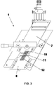
- Figure 3 shows the same components as in Figure 2 , but said panel 5 was removed for better clarity.
- This Figure shows said slits 11 obtained in said head body 4, from which the coating material pours out; said coating material undergoes suction, so that excess coating material is suctioned back through the connecting piece 2.
- Figure 2 shows a plurality of linear and transversal slits 11, preferably oblique with respect to the direction of forward movement of the panel, whose edge is to be coated. Said slits are arranged side by side, in the sense of forward movement of the panel and cross the body 4, opening on its back, allowing the passage of the coating material coming from a dedicated (not shown) reservoir.
- This coating process allows to recover excess coating material, which is recovered and recycled thanks to the action of suction.
- Figure 4 shows an exploded axonometric view of the coating head 1, wherein the top form 7 and the lower form 7 are removed from their working position.
- the handle bar 9 is rotated so that the top form 7 can be removed, while from screws 10 knobs 18 were removed, which keep the lower form 8 in place during the coating process.
- the lower form 8 is kept integral with said body 4 of coating head 1 through a pair of eyelets 19, each of which is assembled with a pair of screws 10.
- the knobs 18, screwed on screws 10 allow the fixing of the lower form 8 to coating head body 4.
- the top form 7 is provided in its turn with a plurality of slits 13, while the lower form 8 is provided in its turn with a plurality of slits 12.
- Said slits 12 and 13 of the forms are arranged in phase with respect to the slits 11 of body 4, so that coating material can come out and be suctioned. Nonetheless, the top form 7 and lower form 8 can be slid so as to bring them closer together or further apart, and this allows to adjust the overall height of the slits, so that their dimensions is suitable to the thickness of the panel edge to be coated.
- Figure 5 shows the coating head 1 wherein top form 7 and lower form 8 were removed; the handle bar 9 is in the position allowing their removal.
- This Figure shows the presence of the driving wheel 6, adjusting the vertical position of the top form 7 through a pair of guides 14 on which a support 15 slides; on said support two bearings 16 are fixed.
- said bearings 16 are engaged in a slot 17 of the form 7 itself.
- the rotation of the adjusting wheel 6 turns a threaded rod, which engages in a stationary nut integral with the sliding support 15; therefore said rotation leads, according to the direction of rotation, to a forward or backward translation of said sliding support 15.
- the embodiment shown in the figures provides for a specific mechanism for adjusting the vertical position of the top form 7, this specific embodiment has not to be interpreted as a limitation of the more general teaching according to which the top form 7 is supported by a displacing mechanism for adjusting the vertical position of the said top form 7 in relation to the position of the lower form 8 for variating the nozzle size and a control organ is provided for driving the said displacing mechanism.
- top form 7 and said lower form 8 can be brought closer together or further apart, preferably comprising an adjusting wheel 6 which controls a translation mechanism of a support 15, two guides 14 on which said support slides 15 and a pair of bearings 16, allowing a precise adjustments of the nozzle size through a variation of the reciprocal distance of the top and upper forms 7, 8 one from the other by a manual control action through the wheel 6.
- top forms 7 and lower forms 8 are produced, reproducing its outline.
- a human operator manually replaces the top form 7 and lower form 8 from coating head 1.
- the radius of curvature of a panel edge is the same, but the thickness of the panel 5 is different between batches, bringing the top form 7 and the lower form 8 closer together or further apart through adjusting wheel 6 will be sufficient.
- Figures 6A, 6B, 6C show three lateral views similar to that shown in Figure 1 , wherein the vacuum coating head is used to coat three different panels having different shapes.
- Panel 5A has an asymmetric bull nose edge
- panel 5B has a bull nose edge with a tooth
- panel 5C has a symmetrical bull nose edge.
- the vacuum coating head 1 is provided with specifically produced forms 7 and 8, which are suitable for each of these shapes; moreover, the forms 7 and 8 can be brought closer together of further apart to adapt them to the thickness of each single panel 5A, 5B, 5C.
- Top forms 7 and lower forms 8 are produced through machine tool in a productive step completely distinct from coating step, so as to reduce to a minimum the downtime of the coating machine which is necessary for the set-up of said coating machine comprising the vacuum head 1.
- top forms 7 and lower forms 8 are obtained starting from stainless steel blades through removal of material, even if the use of other materials and technologies is possible, e.g. 3D-printing or plastic moulding of a plastic material having a sufficient hardness.
- top forms 7 and lower forms 8 are faster and easier with respect to the plate packs described in IT BO2011A000287 .
- top form 7 and the lower form 8 are obtained not starting from a solid body, but from a plate pack wherein plates are integrally connected to each other so as to form a unique body (i.e., the plates cannot slide on each other as described in IT BO2011A000287 ).
- the coating machine can be provided with a stock of different top forms 7 and lower forms 8, which are picked up by a robotic arm and placed in the correct position with respect to the body 4 of coating head 1.
- the handle bar 9, the adjusting wheel 6, and the knobs 18 of screws 10 will be replaced by suitable fixing and adjusting elements well-known to the skilled man.
- the method of panel recognition through barcodes is used: when a production batch has to be changed, a human operator detects the barcode on the following batch.
- An informatics system saves all the dimensional characteristics relating to batches, and therefore the control system of the coating machine, wherein the data for each batch were previously saved, can set-up the coating machine arranging the suitable top forms 7 and lower forms 8 at a suitable distance according to the detected barcode and associated to the batch to be produced.
- top forms 7 and lower forms 8 replacement Through the automation of top forms 7 and lower forms 8 replacement, the manual set-up time, typically lasting some minutes, can be reduced to a set-up time lasting some seconds, obtaining a reduction of set-up time of an order of magnitude. This is especially desirable in the case of batch processing, each of which comprises a small number of pieces, which is the productive reality which most of furniture manufacturers face today.
Landscapes
- Coating Apparatus (AREA)
- Application Of Or Painting With Fluid Materials (AREA)
- Laminated Bodies (AREA)
Abstract
Description
- The present invention relates to the technical field of machines for coating panels made of sundry materials (wood, glass, fibrocement, etc.) through the technology of coating with the aid of suction, as will better explained in the following. In particular, the present invention relates to a coating head, a so-called vacuum coating head.
- In the art, coating machines of this kind are known, comprising a head provided with a chamber supplied with a coating product to be used for coating the panel. Documents of the known art are e.g.
US 5,976,249 of JOSEF SCHIELE OHG andIT 1.341.136 - The application
IT BO2011A000287 - The slits in the recess allow to coat the edge with a constant and continuous layer of coating material, thanks to the continuous forward movement with constant speed of the panel to be coated, through the suctioning action performed by the slits which continuously suction air through the recess of the coating head and along the surface to be coated of panel edge.
- The viscosity of the coating material, the flow rate of the suctioning, the outline and the dimensions of the recess with relation to the edge outline determine the coating on the edge which, with the longitudinal speed of the forward movement of the panel, determine the thickness of the coating deposed on the edge itself. The suctioning action performed by the slits, in addition to suctioning coating material and preventing its leakage from the coating head, acts as control dosing of the coating material along the panel edge, ensuring a constant thickness of the coating material according to its viscosity and the constancy over time of the pressure of said coating material, panel forward movement, and distance of the edge from the walls of the recess of coating head.
- Nonetheless, in use the solution of a coating head realized through a plates pack is not free from drawbacks.
- A first drawback of the solution described in
IT BO2011A000287 - A second drawback is the fact that, with the change of thickness of the panel, the plate pack must be adjusted to the new shape.
- Aim of the present invention is providing a coating head having a nozzle realized through an assembly of two forms which cooperate to provide an opening having dimensions and shape suitable for the edge to be coated, which can be easily and rapidly replaced with the change of panel edge outline.
- This object is achieved by an apparatus and a method having the features of the independent claims. Advantageous embodiments and refinements are specified in claims dependent thereon.
- The coating head according to the present invention comprises:
- head body;
- at least a top form;
- at least a lower form;
- It is apparent that for every distinct edge to be coated having its own form, the recess has a corresponding specific shape.
- The method according to the present invention comprises the following steps:
- Producing a first pair of top and lower forms which together work as a specific nozzle for a given first edge, the forms being preferably produced removing from a block the excess material;
- Assembling, manually or automatically, said first pair of top and lower form on the supporting body, in correspondence to the exit slits of the coating material and of vacuum transmission present on the body itself;
- Coating the panels with an edge having a first given shape;
- When the batch of panels is finished and the following batch, having a different given edge, has to be coated, replacing, manually or automatically, the first pair of top and lower forms having the outline corresponding to the first batch with a second pair of top and lower forms having the outline corresponding to the second batch.
- In particular, the replacement of the first pair of forms with the second pair of forms makes the set-up of the machine very rapid when the replacement is automatically performed by the machine itself. Nonetheless, it is worth noting that, even in the case the replacement is manually performed by a human operator, the set-up time is reduced, in that all the steps of fine-tuning of the recess outline are moved to the step wherein the forms are produced, preferably obtaining them by removal of material from a block.
- A first advantage of the present invention consists in the possibility of a high reduction of the downtime of the coating machine connected with the replacement of the recess of the coating head.
- A second advantage lies in the fact that, with the change of panel thickness, its outline being the same as in the preceding batch, said pair of forms does not need replacement, but the operator has simply to adjust their respective distance to bring the two forms at a distance suitable to the present batch of panels.
- A third advantage of the present invention is in the possibility of automating the set-up of the coating machine, providing it with different forms having different outlines, and with a system allowing their replacement without human operator.
- Further advantages and properties of the present invention are disclosed in the following description, in which exemplary embodiments of the present invention are explained in detail based on the drawings:
- Figure 1
- Lateral view of a vacuum coating head according to the present invention with panel;
- Figure 2
- Frontal view of a coating head with panel;
- Figure 3
- Frontal view of a coating head without panel;
- Figure 4
- Exploded view of an axonometric view of the coating head wherein the top and lower forms were removed;
- Figure 5
- Frontal view of the coating head wherein the top and lower forms were removed;
- Figure 6A, 6B, 6C
- Lateral view of three vacuum coating heads according to the present invention, each head coating a panel having a distinct edge shape.
-
Figure 1 shows in a lateral view avacuum coating head 1 having a connectingpiece 2 between said head and its relative system generating vacuum (not shown); two pipes 3 supplying coating material to saidhead 1; a body 4 whereinslits 11 are obtained (visible in the following Figures). Moreover,Figure 1 shows apanel 5 in the position wherein it stands while it is coated.Figure 1 shows an adjusting wheel 6 allowing the adjustment of recess dimensions according to the thickness of the panel to be coated; atop form 7 and alower form 8. -
Figure 2 shows saidvacuum coating head 1 in a frontal view; therefore, the connectingpiece 2 and the pipes 3 are not visible. On the other hand, a handle bar 9, which allows to fix thetop form 7, and fourknobs 18 for fixing thelower form 8 become visible. In this view, thepanel 5 is shown in the position in which it stands while it is coated. -
Figure 3 shows the same components as inFigure 2 , but saidpanel 5 was removed for better clarity. This Figure shows saidslits 11 obtained in said head body 4, from which the coating material pours out; said coating material undergoes suction, so that excess coating material is suctioned back through the connectingpiece 2.Figure 2 shows a plurality of linear andtransversal slits 11, preferably oblique with respect to the direction of forward movement of the panel, whose edge is to be coated. Said slits are arranged side by side, in the sense of forward movement of the panel and cross the body 4, opening on its back, allowing the passage of the coating material coming from a dedicated (not shown) reservoir. - This coating process allows to recover excess coating material, which is recovered and recycled thanks to the action of suction.
-
Figure 4 shows an exploded axonometric view of thecoating head 1, wherein thetop form 7 and thelower form 7 are removed from their working position. The handle bar 9 is rotated so that thetop form 7 can be removed, while fromscrews 10knobs 18 were removed, which keep thelower form 8 in place during the coating process. Thelower form 8 is kept integral with said body 4 ofcoating head 1 through a pair ofeyelets 19, each of which is assembled with a pair ofscrews 10. Theknobs 18, screwed onscrews 10, allow the fixing of thelower form 8 to coating head body 4. - The
top form 7 is provided in its turn with a plurality ofslits 13, while thelower form 8 is provided in its turn with a plurality ofslits 12. Saidslits slits 11 of body 4, so that coating material can come out and be suctioned. Nonetheless, thetop form 7 andlower form 8 can be slid so as to bring them closer together or further apart, and this allows to adjust the overall height of the slits, so that their dimensions is suitable to the thickness of the panel edge to be coated. -
Figure 5 shows thecoating head 1 whereintop form 7 andlower form 8 were removed; the handle bar 9 is in the position allowing their removal. This Figure shows the presence of the driving wheel 6, adjusting the vertical position of thetop form 7 through a pair ofguides 14 on which asupport 15 slides; on said support twobearings 16 are fixed. When thetop form 7 is in its assembled status, saidbearings 16 are engaged in aslot 17 of theform 7 itself. The rotation of the adjusting wheel 6 turns a threaded rod, which engages in a stationary nut integral with the slidingsupport 15; therefore said rotation leads, according to the direction of rotation, to a forward or backward translation of said slidingsupport 15. - Although the embodiment shown in the figures provides for a specific mechanism for adjusting the vertical position of the
top form 7, this specific embodiment has not to be interpreted as a limitation of the more general teaching according to which thetop form 7 is supported by a displacing mechanism for adjusting the vertical position of the saidtop form 7 in relation to the position of thelower form 8 for variating the nozzle size and a control organ is provided for driving the said displacing mechanism. - The specific solution disclosed in the drawings is a preferred embodiment wherein said
top form 7 and saidlower form 8 can be brought closer together or further apart, preferably comprising an adjusting wheel 6 which controls a translation mechanism of asupport 15, twoguides 14 on which said support slides 15 and a pair ofbearings 16, allowing a precise adjustments of the nozzle size through a variation of the reciprocal distance of the top andupper forms - According to the outline of the
panel 5 to be coated, differenttop forms 7 andlower forms 8 are produced, reproducing its outline. When there is a change of production batch, a human operator manually replaces thetop form 7 andlower form 8 fromcoating head 1. When the radius of curvature of a panel edge is the same, but the thickness of thepanel 5 is different between batches, bringing thetop form 7 and thelower form 8 closer together or further apart through adjusting wheel 6 will be sufficient. -
Figures 6A, 6B, 6C show three lateral views similar to that shown inFigure 1 , wherein the vacuum coating head is used to coat three different panels having different shapes.Panel 5A has an asymmetric bull nose edge,panel 5B has a bull nose edge with a tooth, andpanel 5C has a symmetrical bull nose edge. Thevacuum coating head 1 is provided with specifically producedforms forms single panel -
Top forms 7 andlower forms 8 are produced through machine tool in a productive step completely distinct from coating step, so as to reduce to a minimum the downtime of the coating machine which is necessary for the set-up of said coating machine comprising thevacuum head 1. Preferably,top forms 7 andlower forms 8 are obtained starting from stainless steel blades through removal of material, even if the use of other materials and technologies is possible, e.g. 3D-printing or plastic moulding of a plastic material having a sufficient hardness. - It is worth noting that the cleaning of
top forms 7 andlower forms 8 is faster and easier with respect to the plate packs described inIT BO2011A000287 - In an alternative embodiment, the
top form 7 and thelower form 8 are obtained not starting from a solid body, but from a plate pack wherein plates are integrally connected to each other so as to form a unique body (i.e., the plates cannot slide on each other as described inIT BO2011A000287 - The described systems using two forms, a
top form 7 and alower form 8, with a device adjusting their relative position, paves the way to an automation of the set-up of the coating machine comprising the vacuum coating head according to the present invention. - In fact, the coating machine can be provided with a stock of different
top forms 7 andlower forms 8, which are picked up by a robotic arm and placed in the correct position with respect to the body 4 ofcoating head 1. Obviously, in this case the handle bar 9, the adjusting wheel 6, and theknobs 18 ofscrews 10 will be replaced by suitable fixing and adjusting elements well-known to the skilled man. - In the furniture industry, the method of panel recognition through barcodes is used: when a production batch has to be changed, a human operator detects the barcode on the following batch. An informatics system saves all the dimensional characteristics relating to batches, and therefore the control system of the coating machine, wherein the data for each batch were previously saved, can set-up the coating machine arranging the suitable
top forms 7 andlower forms 8 at a suitable distance according to the detected barcode and associated to the batch to be produced. - Through the automation of
top forms 7 andlower forms 8 replacement, the manual set-up time, typically lasting some minutes, can be reduced to a set-up time lasting some seconds, obtaining a reduction of set-up time of an order of magnitude. This is especially desirable in the case of batch processing, each of which comprises a small number of pieces, which is the productive reality which most of furniture manufacturers face today. - 1
- Vacuum coating head
- 2
- Connecting piece
- 3
- Pipes
- 4
- Body with slits
- 5
- Panel
- 6
- Adjusting wheel
- 7
- Top form
- 8
- Lower form
- 9
- Handle bar
- 10
- Screws
- 11
- Slits
- 12
- Slits of top form
- 13
- Slits of lower form
- 14
- Guide
- 15
- Support
- 16
- Cuscinetti
- 17
- Slot
- 18
- Knobs
- 19
- Eyelets
Claims (9)
- Vacuum coating head (1) for coating panel (5) or other essentially flat pieces edges comprising a recess reproducing with suitable increase the outline of the panel to be coated, which recess is configured to work in a condition facing an edge to be coated, which is slid along said recess crossing it from side to side; in said recess at least a nozzle comprising a plurality of slits (11, 12, 13) is open, to apply a coating material on said edge, in which recess also suction nozzles (11, 12, 13) are open controlling said coating step, said recess comprising:- a body (4) of said head (1) provided with said at least nozzle in the form of a plurality of slits (11);- a top form (7) for upward limiting said recess, comprising a plurality of slits (13);- a lower form (8) for downward limiting said recess, comprising a plurality of slits (12);characterized in that upward and downward limitation of said recess is obtained through said forms (7, 8) made each of a unique solid body, having a shape complementary to the edge of the panel to be coated and.
wherein said top form (7) and said lower form (8) can be brought closer together or further apart, allowing the variation and adjustment of the nozzle size, by means of a displacement mechanism (14, 15, 16) bearing at least one of the said forms (7, 8) preferably the said top form (7) and which mechanism is driven by a displacement control organ (6). - Vacuum coating head according to claim 1, wherein said displacement mechanism for adjusting the nozzle size comprises an adjusting wheel (6) which controls a translation mechanism of a support (15), two guides (14) on which said support slides (15) and a pair of bearings (16) connecting the said top form (7) said support (15).
- Vacuum coating head according to claim 1 or 2, wherein said top form (7) and said lower form (8) can be brought closer together or further apart working on an adjusting device, preferably comprising rapid tightening screws (10) with knobs (18) and slots (19) provided in said lower form (8) and oriented in a direction bringing said lower form (8) closer together or further apart with respect to said top form (7).
- Vacuum coating head according to one of the preceding claims, wherein said slits (12) of lower form (8) and said slits (13) of top form (7) are arranged in phase with said slits (11) of head body (4), the overall height of nozzles being adjustable by bringing closer together or further apart said top form (7) and lower form (8).
- Vacuum coating head according to one of the preceding claims, wherein said top forms (7) and/or lower forms (8) are obtained by processing a pack of plates arranged so that they cannot slide on each other, so forming a solid body.
- Method for coating panel edges or other essentially planar pieces making use of a coating head according to claims 1-5, comprising the following steps:- Producing a first pair of top form (7) and lower form (8) which together work as a specific nozzle having an outline complementary to the outline of a given first edge;- Assembling, manually or automatically, said first pair of top and lower forms (7, 8) on the supporting body (4), in correspondence to the exit slits (11) of the coating material and of vacuum transmission present on the body itself at a suitable distance from each other;- Coating the panels (5) with an edge having a first given shape;- When a first batch of panels is finished and a second batch, having a different given edge, has to be coated, replacing, manually or automatically, the first pair of top and lower forms (7, 8) having the outline corresponding to said first batch with a second pair of top and lower forms (7, 8) having the outline corresponding to a given second batchand wherein the radius of curvature of panel edge being equal, and panel (5) thickness being different, said top form (7) and lower form (8) are brought closer together or further apart, without the need of replacement.
- Method for coating panel edges or other essentially planar pieces according to claim 6, wherein top and lower forms (7, 8) are produced in a productive step distinct form the coating step, preferably before said coating step and through removal of material by a machine tool.
- Method for coating panel edges or other essentially planar pieces according to claim 6 or 7, wherein the set-up of the coating machine is performed automatically by picking the suitable top form (7) and lower form (8) up from a stock inside the coating machine through a robotic arm, and fixing them with suitable fixing means to said coating head (1).
- Method for coating panel edges or other essentially planar pieces according to claim 8, wherein the dimensions of each production batch are saved in the coating machine comprising said coating head (1), at least for what concerns the features of shape and dimensions of edge outline, and when passing from the working of a first batch to the working of a subsequent second batch, the set-up of the coating machine occurs reading the barcode of said second production batch, which records the dimensions needed for picking up and fixing said top form (7) and lower form (8) to said vacuum coating head (1), which forms are identified through said barcode, taken and mounted to replace the forms used for said first batch.
Applications Claiming Priority (1)
| Application Number | Priority Date | Filing Date | Title |
|---|---|---|---|
| IT102016000109468A IT201600109468A1 (en) | 2016-10-28 | 2016-10-28 | VACUUM TYPE PAINTING HEAD, ADAPTABLE TO THE PROFILE OF THE PANEL OR OTHER MANUFACTURED ITEMS TO TREAT |
Publications (1)
| Publication Number | Publication Date |
|---|---|
| EP3315210A1 true EP3315210A1 (en) | 2018-05-02 |
Family
ID=58010292
Family Applications (1)
| Application Number | Title | Priority Date | Filing Date |
|---|---|---|---|
| EP17197342.3A Withdrawn EP3315210A1 (en) | 2016-10-28 | 2017-10-19 | Coating head, adaptable to the outline of a panel edge or other pieces to be coated |
Country Status (3)
| Country | Link |
|---|---|
| EP (1) | EP3315210A1 (en) |
| CN (1) | CN108014964A (en) |
| IT (1) | IT201600109468A1 (en) |
Cited By (3)
| Publication number | Priority date | Publication date | Assignee | Title |
|---|---|---|---|---|
| CN115007392A (en) * | 2022-06-20 | 2022-09-06 | 信丰骏达电子科技有限公司 | PCB circuit board silica gel coating device |
| IT202200005738A1 (en) | 2022-03-23 | 2023-09-23 | Cefla Soc Cooperativa | METHOD FOR PAINTING PANELS USING VACUUM HEADS |
| IT202200005726A1 (en) | 2022-03-23 | 2023-09-23 | Cefla Soc Cooperativa | VACUUM HEAD FOR PAINTING PANEL EDGES |
Families Citing this family (1)
| Publication number | Priority date | Publication date | Assignee | Title |
|---|---|---|---|---|
| PL3885052T3 (en) * | 2020-03-24 | 2023-03-27 | Akzenta Paneele + Profile Gmbh | Edge coating of a panel with a coating medium |
Citations (5)
| Publication number | Priority date | Publication date | Assignee | Title |
|---|---|---|---|---|
| US5976249A (en) | 1996-10-11 | 1999-11-02 | Josef Schiele Ohg | Varnishing head |
| WO2002053296A1 (en) * | 2001-01-08 | 2002-07-11 | Schiele Josef Ohg | Edge coating device |
| ITFI20090093A1 (en) * | 2009-05-05 | 2010-11-06 | Makor S R L Unipersonale | DEVICE FOR COATING RIGID PANELS WITH LIQUID PRODUCTS |
| ITBO20110287A1 (en) | 2011-05-20 | 2012-11-21 | Sorbini Srl | VACUUM TYPE PAINTING HEAD, ADAPTABLE TO THE PROFILE OF THE BOARD OF PANELS OR OTHER MANUFACTURED ITEMS. |
| US20150069150A1 (en) * | 2013-09-10 | 2015-03-12 | Armstrong World Industries, Inc. | System for applying a coating to a workpiece |
Family Cites Families (6)
| Publication number | Priority date | Publication date | Assignee | Title |
|---|---|---|---|---|
| KR102218589B1 (en) * | 2013-06-20 | 2021-02-23 | 삼성디스플레이 주식회사 | Apparatus for coating resin, method thereof and method for forming resin layer using the same |
| US9266141B2 (en) * | 2013-09-10 | 2016-02-23 | Awi Licensing Company | System for applying a coating to a workpiece |
| DE102014110375A1 (en) * | 2014-07-23 | 2016-01-28 | Fraunhofer-Gesellschaft zur Förderung der angewandten Forschung e.V. | Method and device for producing an application of a pasty and / or liquid medium |
| CN204235731U (en) * | 2014-09-25 | 2015-04-01 | 嘉兴顺联橡塑机械有限公司 | A kind of spray nozzle device |
| CN204953252U (en) * | 2015-08-29 | 2016-01-13 | 苏州高新区华成电子有限公司 | A glue dripping machine for diode |
| JP6063070B2 (en) * | 2016-01-11 | 2017-01-18 | 金原 茂 | Adhesive application head |
-
2016
- 2016-10-28 IT IT102016000109468A patent/IT201600109468A1/en unknown
-
2017
- 2017-10-19 EP EP17197342.3A patent/EP3315210A1/en not_active Withdrawn
- 2017-10-27 CN CN201711026376.XA patent/CN108014964A/en active Pending
Patent Citations (5)
| Publication number | Priority date | Publication date | Assignee | Title |
|---|---|---|---|---|
| US5976249A (en) | 1996-10-11 | 1999-11-02 | Josef Schiele Ohg | Varnishing head |
| WO2002053296A1 (en) * | 2001-01-08 | 2002-07-11 | Schiele Josef Ohg | Edge coating device |
| ITFI20090093A1 (en) * | 2009-05-05 | 2010-11-06 | Makor S R L Unipersonale | DEVICE FOR COATING RIGID PANELS WITH LIQUID PRODUCTS |
| ITBO20110287A1 (en) | 2011-05-20 | 2012-11-21 | Sorbini Srl | VACUUM TYPE PAINTING HEAD, ADAPTABLE TO THE PROFILE OF THE BOARD OF PANELS OR OTHER MANUFACTURED ITEMS. |
| US20150069150A1 (en) * | 2013-09-10 | 2015-03-12 | Armstrong World Industries, Inc. | System for applying a coating to a workpiece |
Cited By (5)
| Publication number | Priority date | Publication date | Assignee | Title |
|---|---|---|---|---|
| IT202200005738A1 (en) | 2022-03-23 | 2023-09-23 | Cefla Soc Cooperativa | METHOD FOR PAINTING PANELS USING VACUUM HEADS |
| IT202200005726A1 (en) | 2022-03-23 | 2023-09-23 | Cefla Soc Cooperativa | VACUUM HEAD FOR PAINTING PANEL EDGES |
| EP4249135A1 (en) | 2022-03-23 | 2023-09-27 | Cefla Societa' Cooperativa | Method for coating panel edges through vacuum coating heads |
| EP4249132A1 (en) | 2022-03-23 | 2023-09-27 | Cefla Societa' Cooperativa | Vacuum coating head for coating panel edges |
| CN115007392A (en) * | 2022-06-20 | 2022-09-06 | 信丰骏达电子科技有限公司 | PCB circuit board silica gel coating device |
Also Published As
| Publication number | Publication date |
|---|---|
| IT201600109468A1 (en) | 2018-04-28 |
| CN108014964A (en) | 2018-05-11 |
Similar Documents
| Publication | Publication Date | Title |
|---|---|---|
| EP3315210A1 (en) | Coating head, adaptable to the outline of a panel edge or other pieces to be coated | |
| RU2433009C2 (en) | Method and device to manufacture bent spring elements | |
| EP3266592A1 (en) | Vamp 3d-printing system | |
| EP0661135A1 (en) | Method to hone curved and shaped profiles and honing machine to carry out such method | |
| RU2696473C1 (en) | Sheet glass processing device | |
| KR101759530B1 (en) | Automatic process device for moter shaft | |
| EP3247810B1 (en) | Leather punching machine | |
| US4945959A (en) | Device for planing and molding surface textures in wood boards | |
| CN104608216B (en) | A kind of hypotenuse plank automatic slotting device and processing method thereof | |
| EP4334098A1 (en) | Manufacturing system and method for manufacturing articles made of compacted ceramic powder | |
| CN109732453A (en) | Multi-panel abnormity wire drawing polishing machine | |
| KR20170022032A (en) | V-cutting Machine | |
| US10471488B2 (en) | Machine for bending sheet metal | |
| UA94247C2 (en) | Edge trimming machine | |
| DK1880838T3 (en) | Device and method for making a laminated body | |
| KR100609075B1 (en) | Metal Rod Slope Processing Machine | |
| EP2344306B1 (en) | Gluing apparatus for gluing ends of wood veneer together | |
| KR102183037B1 (en) | Surface machining device | |
| CN114555294B (en) | Device and method for the laterally precisely defined application of abrasive belts in abrasive belt grinding machines in continuous operation | |
| US4650380A (en) | Wire shaving apparatus | |
| WO2004099448A2 (en) | Machine for machining sheet materials such as leather, synthetic materials or similar | |
| KR20200013186A (en) | A Thomson device with rotary type magnetic cylinder equipped with flexible blade | |
| JP2013230683A (en) | Method of operating book forming press machine | |
| ITMO20100054A1 (en) | CUTTING MACHINE FOR LASTRIFORMS, PARTICULARLY FOR CUTTING CERAMIC TILES, NATURAL AND SIMILAR STONES | |
| CN205521548U (en) | Automatic blanking machine of refrigerator temperature controller lead wire sheath |
Legal Events
| Date | Code | Title | Description |
|---|---|---|---|
| PUAI | Public reference made under article 153(3) epc to a published international application that has entered the european phase |
Free format text: ORIGINAL CODE: 0009012 |
|
| STAA | Information on the status of an ep patent application or granted ep patent |
Free format text: STATUS: THE APPLICATION HAS BEEN PUBLISHED |
|
| AK | Designated contracting states |
Kind code of ref document: A1 Designated state(s): AL AT BE BG CH CY CZ DE DK EE ES FI FR GB GR HR HU IE IS IT LI LT LU LV MC MK MT NL NO PL PT RO RS SE SI SK SM TR |
|
| AX | Request for extension of the european patent |
Extension state: BA ME |
|
| STAA | Information on the status of an ep patent application or granted ep patent |
Free format text: STATUS: REQUEST FOR EXAMINATION WAS MADE |
|
| 17P | Request for examination filed |
Effective date: 20181030 |
|
| RBV | Designated contracting states (corrected) |
Designated state(s): AL AT BE BG CH CY CZ DE DK EE ES FI FR GB GR HR HU IE IS IT LI LT LU LV MC MK MT NL NO PL PT RO RS SE SI SK SM TR |
|
| STAA | Information on the status of an ep patent application or granted ep patent |
Free format text: STATUS: EXAMINATION IS IN PROGRESS |
|
| 17Q | First examination report despatched |
Effective date: 20190820 |
|
| STAA | Information on the status of an ep patent application or granted ep patent |
Free format text: STATUS: THE APPLICATION IS DEEMED TO BE WITHDRAWN |
|
| 18D | Application deemed to be withdrawn |
Effective date: 20220628 |