EP4249129A1 - Zentrifugalbatterie-flüssigkeitseinspritzmechanismus und flüssigkeitseinspritzverfahren dafür - Google Patents
Zentrifugalbatterie-flüssigkeitseinspritzmechanismus und flüssigkeitseinspritzverfahren dafür Download PDFInfo
- Publication number
- EP4249129A1 EP4249129A1 EP22201212.2A EP22201212A EP4249129A1 EP 4249129 A1 EP4249129 A1 EP 4249129A1 EP 22201212 A EP22201212 A EP 22201212A EP 4249129 A1 EP4249129 A1 EP 4249129A1
- Authority
- EP
- European Patent Office
- Prior art keywords
- liquid injection
- liquid
- wetted
- outlet head
- piston
- Prior art date
- Legal status (The legal status is an assumption and is not a legal conclusion. Google has not performed a legal analysis and makes no representation as to the accuracy of the status listed.)
- Granted
Links
Images


Classifications
-
- B—PERFORMING OPERATIONS; TRANSPORTING
- B05—SPRAYING OR ATOMISING IN GENERAL; APPLYING FLUENT MATERIALS TO SURFACES, IN GENERAL
- B05B—SPRAYING APPARATUS; ATOMISING APPARATUS; NOZZLES
- B05B9/00—Spraying apparatus for discharge of liquids or other fluent material, without essentially mixing with gas or vapour
- B05B9/03—Spraying apparatus for discharge of liquids or other fluent material, without essentially mixing with gas or vapour characterised by means for supplying liquid or other fluent material
- B05B9/04—Spraying apparatus for discharge of liquids or other fluent material, without essentially mixing with gas or vapour characterised by means for supplying liquid or other fluent material with pressurised or compressible container; with pump
- B05B9/0403—Spraying apparatus for discharge of liquids or other fluent material, without essentially mixing with gas or vapour characterised by means for supplying liquid or other fluent material with pressurised or compressible container; with pump with pumps for liquids or other fluent material
- B05B9/0409—Spraying apparatus for discharge of liquids or other fluent material, without essentially mixing with gas or vapour characterised by means for supplying liquid or other fluent material with pressurised or compressible container; with pump with pumps for liquids or other fluent material the pumps being driven by a hydraulic or a pneumatic fluid
-
- H—ELECTRICITY
- H01—ELECTRIC ELEMENTS
- H01M—PROCESSES OR MEANS, e.g. BATTERIES, FOR THE DIRECT CONVERSION OF CHEMICAL ENERGY INTO ELECTRICAL ENERGY
- H01M50/00—Constructional details or processes of manufacture of the non-active parts of electrochemical cells other than fuel cells, e.g. hybrid cells
- H01M50/60—Arrangements or processes for filling or topping-up with liquids; Arrangements or processes for draining liquids from casings
- H01M50/609—Arrangements or processes for filling with liquid, e.g. electrolytes
- H01M50/627—Filling ports
-
- B—PERFORMING OPERATIONS; TRANSPORTING
- B05—SPRAYING OR ATOMISING IN GENERAL; APPLYING FLUENT MATERIALS TO SURFACES, IN GENERAL
- B05B—SPRAYING APPARATUS; ATOMISING APPARATUS; NOZZLES
- B05B13/00—Machines or plants for applying liquids or other fluent materials to surfaces of objects or other work by spraying, not covered by groups B05B1/00 - B05B11/00
- B05B13/02—Means for supporting work; Arrangement or mounting of spray heads; Adaptation or arrangement of means for feeding work
- B05B13/0278—Arrangement or mounting of spray heads
-
- B—PERFORMING OPERATIONS; TRANSPORTING
- B05—SPRAYING OR ATOMISING IN GENERAL; APPLYING FLUENT MATERIALS TO SURFACES, IN GENERAL
- B05B—SPRAYING APPARATUS; ATOMISING APPARATUS; NOZZLES
- B05B13/00—Machines or plants for applying liquids or other fluent materials to surfaces of objects or other work by spraying, not covered by groups B05B1/00 - B05B11/00
- B05B13/06—Machines or plants for applying liquids or other fluent materials to surfaces of objects or other work by spraying, not covered by groups B05B1/00 - B05B11/00 specially designed for treating the inside of hollow bodies
- B05B13/0627—Arrangements of nozzles or spray heads specially adapted for treating the inside of hollow bodies
-
- H—ELECTRICITY
- H01—ELECTRIC ELEMENTS
- H01M—PROCESSES OR MEANS, e.g. BATTERIES, FOR THE DIRECT CONVERSION OF CHEMICAL ENERGY INTO ELECTRICAL ENERGY
- H01M10/00—Secondary cells; Manufacture thereof
- H01M10/05—Accumulators with non-aqueous electrolyte
- H01M10/058—Construction or manufacture
-
- H—ELECTRICITY
- H01—ELECTRIC ELEMENTS
- H01M—PROCESSES OR MEANS, e.g. BATTERIES, FOR THE DIRECT CONVERSION OF CHEMICAL ENERGY INTO ELECTRICAL ENERGY
- H01M50/00—Constructional details or processes of manufacture of the non-active parts of electrochemical cells other than fuel cells, e.g. hybrid cells
- H01M50/60—Arrangements or processes for filling or topping-up with liquids; Arrangements or processes for draining liquids from casings
- H01M50/609—Arrangements or processes for filling with liquid, e.g. electrolytes
-
- B—PERFORMING OPERATIONS; TRANSPORTING
- B05—SPRAYING OR ATOMISING IN GENERAL; APPLYING FLUENT MATERIALS TO SURFACES, IN GENERAL
- B05B—SPRAYING APPARATUS; ATOMISING APPARATUS; NOZZLES
- B05B15/00—Details of spraying plant or spraying apparatus not otherwise provided for; Accessories
- B05B15/60—Arrangements for mounting, supporting or holding spraying apparatus
- B05B15/68—Arrangements for adjusting the position of spray heads
-
- H—ELECTRICITY
- H01—ELECTRIC ELEMENTS
- H01M—PROCESSES OR MEANS, e.g. BATTERIES, FOR THE DIRECT CONVERSION OF CHEMICAL ENERGY INTO ELECTRICAL ENERGY
- H01M50/00—Constructional details or processes of manufacture of the non-active parts of electrochemical cells other than fuel cells, e.g. hybrid cells
- H01M50/60—Arrangements or processes for filling or topping-up with liquids; Arrangements or processes for draining liquids from casings
-
- H—ELECTRICITY
- H01—ELECTRIC ELEMENTS
- H01M—PROCESSES OR MEANS, e.g. BATTERIES, FOR THE DIRECT CONVERSION OF CHEMICAL ENERGY INTO ELECTRICAL ENERGY
- H01M50/00—Constructional details or processes of manufacture of the non-active parts of electrochemical cells other than fuel cells, e.g. hybrid cells
- H01M50/60—Arrangements or processes for filling or topping-up with liquids; Arrangements or processes for draining liquids from casings
- H01M50/609—Arrangements or processes for filling with liquid, e.g. electrolytes
- H01M50/618—Pressure control
-
- H—ELECTRICITY
- H01—ELECTRIC ELEMENTS
- H01M—PROCESSES OR MEANS, e.g. BATTERIES, FOR THE DIRECT CONVERSION OF CHEMICAL ENERGY INTO ELECTRICAL ENERGY
- H01M50/00—Constructional details or processes of manufacture of the non-active parts of electrochemical cells other than fuel cells, e.g. hybrid cells
- H01M50/60—Arrangements or processes for filling or topping-up with liquids; Arrangements or processes for draining liquids from casings
- H01M50/668—Means for preventing spilling of liquid or electrolyte, e.g. when the battery is tilted or turned over
-
- H—ELECTRICITY
- H01—ELECTRIC ELEMENTS
- H01M—PROCESSES OR MEANS, e.g. BATTERIES, FOR THE DIRECT CONVERSION OF CHEMICAL ENERGY INTO ELECTRICAL ENERGY
- H01M50/00—Constructional details or processes of manufacture of the non-active parts of electrochemical cells other than fuel cells, e.g. hybrid cells
- H01M50/60—Arrangements or processes for filling or topping-up with liquids; Arrangements or processes for draining liquids from casings
- H01M50/673—Containers for storing liquids; Delivery conduits therefor
-
- H—ELECTRICITY
- H01—ELECTRIC ELEMENTS
- H01M—PROCESSES OR MEANS, e.g. BATTERIES, FOR THE DIRECT CONVERSION OF CHEMICAL ENERGY INTO ELECTRICAL ENERGY
- H01M50/00—Constructional details or processes of manufacture of the non-active parts of electrochemical cells other than fuel cells, e.g. hybrid cells
- H01M50/60—Arrangements or processes for filling or topping-up with liquids; Arrangements or processes for draining liquids from casings
- H01M50/673—Containers for storing liquids; Delivery conduits therefor
- H01M50/682—Containers for storing liquids; Delivery conduits therefor accommodated in battery or cell casings
-
- Y—GENERAL TAGGING OF NEW TECHNOLOGICAL DEVELOPMENTS; GENERAL TAGGING OF CROSS-SECTIONAL TECHNOLOGIES SPANNING OVER SEVERAL SECTIONS OF THE IPC; TECHNICAL SUBJECTS COVERED BY FORMER USPC CROSS-REFERENCE ART COLLECTIONS [XRACs] AND DIGESTS
- Y02—TECHNOLOGIES OR APPLICATIONS FOR MITIGATION OR ADAPTATION AGAINST CLIMATE CHANGE
- Y02E—REDUCTION OF GREENHOUSE GAS [GHG] EMISSIONS, RELATED TO ENERGY GENERATION, TRANSMISSION OR DISTRIBUTION
- Y02E60/00—Enabling technologies; Technologies with a potential or indirect contribution to GHG emissions mitigation
- Y02E60/10—Energy storage using batteries
-
- Y—GENERAL TAGGING OF NEW TECHNOLOGICAL DEVELOPMENTS; GENERAL TAGGING OF CROSS-SECTIONAL TECHNOLOGIES SPANNING OVER SEVERAL SECTIONS OF THE IPC; TECHNICAL SUBJECTS COVERED BY FORMER USPC CROSS-REFERENCE ART COLLECTIONS [XRACs] AND DIGESTS
- Y02—TECHNOLOGIES OR APPLICATIONS FOR MITIGATION OR ADAPTATION AGAINST CLIMATE CHANGE
- Y02P—CLIMATE CHANGE MITIGATION TECHNOLOGIES IN THE PRODUCTION OR PROCESSING OF GOODS
- Y02P70/00—Climate change mitigation technologies in the production process for final industrial or consumer products
- Y02P70/50—Manufacturing or production processes characterised by the final manufactured product
Definitions
- the present invention belongs to battery electrolyte injection equipment, and particularly relates to a centrifugal battery liquid injection mechanism and a liquid injection method thereof.
- Electrolyte is an important component of the lithium ion battery
- liquid injection is an important process of injecting a certain amount of electrolyte into the lithium ion battery, and is a very important link in a production process of the lithium ion battery.
- the electrolyte is injected into the battery first, then the whole battery is put into a high-pressure cavity, and the battery is wetted by applying a high pressure through the high-pressure cavity.
- the high-pressure cavity belongs to a third class high pressure vessel, with a high manufacturing cost and a high risk; secondly, a positive and negative pressure circulation process of the high-pressure cavity has a long time period and an unapparent wetting effect; thirdly, there are a complex structure and a cost high; and fourthly, it is difficult to control a liquid injection amount, wherein excessive liquid injection amount easily causes a bulge of the battery, resulting in a poor thickness of the battery; insufficient liquid injection can reduce a capacity of the battery; and uneven liquid injection amount leads to an unstable performance of the battery.
- the present invention puts forward a centrifugal battery liquid injection mechanism and a liquid injection method thereof, with the advantages of apparent wetting effect, high safety performance, low cost and simple operation.
- a centrifugal battery liquid injection mechanism which comprises a liquid injection device and a driving device, wherein,
- one end of the liquid injection device far away from the liquid outlet head is provided with a mechanical valve; and the mechanical valve is connected with an external air pump, so as to drive the piston mechanism to slide in the liquid injection device based air blowing and suction of the air pump.
- the piston mechanism comprises a piston and a driving rod; an edge of the piston clings to an inner wall of the liquid injection device, and the driving rod is connected with the piston, so as to drive the piston to slide along the inner wall of the liquid injection device.
- the centrifugal battery liquid injection mechanism further comprises a supporting device, wherein the liquid injection device and the to-be-wetted device are both connected with the supporting device;
- the driving device is connected with the to-be-wetted device by being connected with the supporting device.
- the supporting device is provided with a bayonet; and the to-be-wetted device is detachably connected with the supporting device by being embedded into the bayonet.
- the supporting device is further provided with a stereoscopic position regulating assembly, and the liquid injection device is connected with the stereoscopic position regulating assembly.
- the liquid outlet head comprises a hose tube.
- a liquid injection method uses the centrifugal battery liquid injection mechanism, and comprises the following steps of:
- the step of injecting the wetting liquid into the liquid injection device through the liquid injection port comprises:
- the liquid injection method further comprises: keeping the liquid injection port in a closed state, opening the liquid outlet head, and controlling the piston mechanism to move towards one end far away from the liquid outlet head, so as to pump out gas in the to-be-wetted device.
- the present invention at least has the following beneficial effects.
- the present invention provides the centrifugal battery liquid injection mechanism and the liquid injection method thereof.
- the centrifugal battery liquid injection mechanism comprises the liquid injection device and the driving device, the liquid injection device is provided with the piston mechanism and the liquid outlet head capable of being opened and closed, and one end of the liquid injection device close to the liquid outlet head is further provided with the liquid injection port capable of being opened and closed; and the liquid injection port is used for injecting the wetting liquid into the liquid injection device.
- the liquid injection device is connected with the to-be-wetted device through the liquid outlet head, so as to inject the wetting liquid into the to-be-wetted device.
- the driving device is connected with the to-be-wetted device for driving the to-be-wetted device to move.
- the to-be-wetted device is detachably connected with the supporting device by arranging the bayonet on the supporting device, so that the to-be-wetted device is disassembled conveniently, and meanwhile, a fixing function of the bayonet improves the safety and the reliability during movement of the to-be-wetted device.
- the liquid outlet head of the liquid injection device is the hose tube or the supporting device is provided with the stereoscopic position adjusting assembly, which is convenient for adjusting an overall position of the liquid outlet head of the liquid injection device or the liquid injection device, so that the to-be-wetted device is conveniently connected with the liquid injection device, and outside air will not enter the to-be-wetted device or the liquid injection device, thus improving a liquid injection efficiency.
- the present invention provides a centrifugal battery liquid injection mechanism and a liquid injection method thereof.
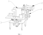
- the centrifugal battery liquid injection mechanism comprises a liquid injection device 2 and a driving device 3, the liquid injection device 2 is provided with a piston mechanism and a liquid outlet head 27 capable of being opened and closed, and one end of the liquid injection device 2 close to the liquid outlet head 27 is further provided with a liquid injection port 11 capable of being opened and closed; and the liquid injection port 11 is used for injecting a wetting liquid into the liquid injection device 2.
- the liquid injection device 2 is connected with a to-be-wetted device 1 through the liquid outlet head 27, so as to inject the wetting liquid into the to-be-wetted device 1.
- the driving device 3 is connected with the to-be-wetted device 1 for driving the to-be-wetted device 1 to move.
- a liquid injection method thereof comprises the following steps of: injecting the wetting liquid into the liquid injection device 2 through the liquid injection port 11; opening the liquid outlet head 27, controlling the piston mechanism to move towards one end of the liquid outlet head 27, and injecting the wetting liquid in the liquid injection device 2 into the to-be-wetted device 1; and controlling the driving device 3 to drive the to-be-wetted device 1 to move, so that the wetting liquid is fully wetted in the to-be-wetted device 1.
- the centrifugal battery liquid injection mechanism and the liquid injection method thereof put forward by the invention have the advantages of apparent wetting effect, high safety performance, low cost and simple operation.
- a centrifugal battery liquid injection mechanism comprises a liquid injection device 2 and a driving device 3.
- the liquid injection device 2 is provided with a piston mechanism 13 and a liquid outlet head 27 capable of being opened and closed.
- One end of the liquid injection device 2 close to the liquid outlet head 27 is further provided with a liquid injection port 11 capable of being opened and closed, and the liquid injection port 11 is used for injecting a wetting liquid into the liquid injection device 2.
- the liquid injection device 2 is connected with a to-be-wetted device 1 through the liquid outlet head 27, so as to inject the wetting liquid into the to-be-wetted device 1.
- the driving device 3 is connected with the to-be-wetted device 1 for driving the to-be-wetted device 1 to move.
- the driving the to-be-wetted device 1 to move may be repetitive movement along multiple points or rotation around a center point.
- the driving device 3 is connected with the to-be-wetted device 1 for driving the to-be-wetted device 1 to rotate around the center point, so that the wetting liquid is fully wetted in the to-be-wetted device 1, thus improving a wetting efficiency.
- the piston mechanism comprises a piston 13, an edge of the piston 13 clings to an inner wall of the liquid injection device 2, and the piston 13 is driven to slide along the inner wall of the liquid injection device 2 under an action of a driving rod or an external air pump, so as to generate a positive pressure and a negative pressure between the liquid outlet head 27 and the piston 13.
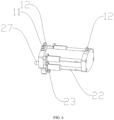
- the piston 13 being driven by the external air pump specifically comprises that: one end of the liquid injection device 2 far away from the liquid outlet head 27 is provided with a mechanical valve 12, and the mechanical valve 12 is connected with the external air pump, so as to drive the piston mechanism to slide in the liquid injection device 2 based on air blowing and suction of the air pump.
- the piston 13 being driven by the driving rod specifically comprises that: the edge of the piston 13 clings to the inner wall of the liquid injection device 2, and the driving rod is connected with the piston 13, so as to drive the piston 13 to slide along the inner wall of the liquid injection device 2.
- the piston 13 is driven by the external air pump, wherein one end of the liquid injection device 2 far away from the liquid outlet head 27 is provided with the mechanical valve 12, and the mechanical valve 12 is connected with the external air pump.
- the piston 13 moves towards one end far away from the liquid outlet head 27; and when air blowing is performed on the liquid injection device 2, the piston 13 moves towards one end close to the liquid outlet head 27, thus injecting the wetting liquid in the liquid injection device 2 into the to-be-wetted device 1.
- the piston 13 is driven by the driving rod, wherein the piston mechanism comprises the piston 13 and the driving rod, the edge of the piston 13 clings to the inner wall of the liquid injection device 2, the driving rod is connected with the piston 13, and the driving rod pushes the piston 13 to move towards one end close to or far away from the liquid outlet head 27.
- the driving rod pushes the piston 13 to move towards one end close to the liquid outlet head 27, the wetting liquid in the liquid injection device 2 is injected into the to-be-wetted device 1.
- one end of the liquid injection device 2 far away from the liquid outlet head 27 is provided with the mechanical valve 12, and the mechanical valve 12 is used for being connected with the external air pump, so as to drive the piston mechanism to slide in the liquid injection device 2 through air blowing and suction of the air pump.
- the piston mechanism comprises the piston 13 and the driving rod, the edge of the piston 13 clings to the inner wall of the liquid injection device 2, and the driving rod is connected with the piston 13, so as to drive the piston 13 to slide along the inner wall of the liquid injection device 2 through the driving rod.
- one end of the liquid injection device 2 close to the liquid outlet head 27 may also be provided with the mechanical valve 12, the mechanical valve 12 is connected with the external air pump for pumping out gas in the liquid injection device 2, so as to ensure a vacuum state of the liquid injection device 2.
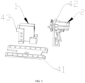
- the centrifugal battery liquid injection mechanism further comprises a supporting device 4, wherein the liquid injection device 2 and the to-be-wetted device 1 are both connected with the supporting device 4.
- the driving device 3 is connected with the to-be-wetted device 1 by being connected with the supporting device 4.
- the supporting device 4 is provided with a bayonet 43; and the to-be-wetted device 1 is detachably connected with the supporting device 4 by being embedded into the bayonet 43.
- the bayonet 43 is a concave structure formed by two limiting blocks, and used for limiting positions of four surfaces of the to-be-wetted device 1.
- front, rear, left and right surfaces of the to-be-wetted device 1 are all within a scope limited by the limiting blocks, and a position of the to-be-wetted device 1 is limited by cooperation of the two limiting blocks, so as to achieve a structural stability and improve a safety of liquid injection.
- the bayonet 43 is a protruding structure
- the to-be-wetted device 1 is provided with a recess
- the to-be-wetted device 1 is limited at the bayonet 43 by cooperation between the protrusion and the recess.
- the liquid outlet head 27 may be a hose tube or a hard tube. It is easier to change a position of the liquid outlet head 27 by using the hose tube, so that a sealing performance between the to-be-wetted device 1 and the liquid injection device 2 is strengthened, and external gas cannot enter the to-be-wetted device 1 or the liquid injection device 2, thus improving the liquid injection efficiency.
- the liquid outlet head has a long service life and is not easy to be damaged by using the hard tube.
- the liquid outlet head 27 comprises the hose tube, and the to-be-wetted device 1 and the liquid injection device 2 are connected through the hose tube.
- the supporting device 4 is further provided with a stereoscopic position regulating assembly, and the liquid injection device 2 is connected with the stereoscopic position regulating assembly.
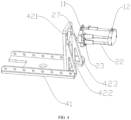
- the supporting device 4 is provided with a bracket 42, and the liquid injection device 2 penetrates through the bracket 42, so that the liquid injection device 2 is detachably connected with the bracket 42.
- the position adjusting assembly is arranged between the liquid injection device 2 and the bracket 42 for adjusting a position of the liquid injection device 2.
- the stereoscopic position regulating assembly is arranged at one end far away from the liquid injection device 2, and a position of the bracket 42 is adjusted through the stereoscopic position regulating assembly, thus adjusting the position of the liquid injection device 2.
- the stereoscopic position regulating assembly is arranged between the liquid injection device 2 and the bracket 42, and the position of the liquid injection device 2 is directly adjusted through the stereoscopic position regulating assembly.
- the supporting device 4 is further provided with a base plate 41, the base plate 41 is welded or threadedly connected with the bracket 42 and the bayonet 43 respectively for fixing the bracket 42 and the bayonet 43.
- Two opposite ends of the base plate 41 are respectively provided with a notch, the notch may be a circle, a rectangle, a triangle or other polygons with more than four sides.
- the notch is the rectangle, so that a cross section of the base plate 41 is H-shaped, the bracket 42 is arranged at one end of the base plate 41, and a bottom portion of the bracket 42 is connected with an edge of the notch.
- the base plate 41, the bracket 42 and the bayonet 43 are provided with hollowed-out portions, and the hollowed-out portions comprise a circle, a triangle, a rectangle or a polygon.
- the polygon refers to a pattern with more than four sides.
- an edge of the base plate 41 and a surface of the bayonet 43 are provided with a plurality of circular hollowed-out portions, and the circular hollowed-out portions are arranged at equal intervals.
- the bracket 42 is provided with a triangular hollowed-out portion and a rectangular hollowed-out portion. An overall weight of the centrifugal battery injection mechanism is reduced and an appearance of a product is improved through the hollowed-out portions arranged in the base plate 41, the bracket 42 and the bayonet 43.
- the bracket 42 comprises a fixed plate 421, a first supporting plate 422 and a second supporting plate 423.
- the first supporting plate 422 and the second supporting plate 423 are connected to two edges of the fixed plate 421, and the first supporting plate 422 and the second supporting plate 423 are triangular, thus having the advantage of stable support.
- Hollowed-out portions inside the first supporting plate 422 and the second supporting plate 423 are also triangular, and a lower portion of the fixed plate 421 is provided with a rectangular hollowed-out portion. The design of the hollowed-out portions saves materials and reduces a product quality on one hand, and realizes an attractive appearance of the product.
- a surface of the liquid injection device 2 is surrounded by a plurality of supporting columns 22, and the supporting columns 22 penetrate through the bracket 42.
- the supporting column 22 is provided with a limiting member 23, and the limiting member 23 abuts against the bracket 42 for fixing the liquid injection device 2 on the bracket 42, thus ensuring a stability of the liquid injection device 2, and ensuring that the liquid injection device 2 is not easy to slide off the bracket 42 to damage the liquid injection device 2.
- the limiting member 23 comprises a limiting sheet and a limiting ring, the limiting sheet and the limiting ring are arranged on the supporting column 22, and a distance between the limiting sheet and the limiting ring is no less than a thickness of the bracket 42, so that one sides of the limiting sheet and the limiting ring close to the bracket 42 abut against the bracket 42, thus positioning the liquid injection device 2 and making a structure of the liquid injection device 2 more stable.
- the limiting member 23 is a screw, a bolt or a pin, and the limiting member 23 is connected to the bracket 42 to position the liquid injection device 2, thus making the structure of the liquid injection device 2 more stable.
- the centrifugal battery liquid injection mechanism further comprises a controller and a monitoring module.
- An input end of the controller is electrically connected with the monitoring module, and an output end of the controller is electrically connected with the driving device 3.
- the monitoring module is configured for detecting liquid injection information of the to-be-wetted device 1 and transmitting the obtained liquid injection information to the controller.
- the controller is used for receiving the liquid injection information transmitted from the monitoring module, reading preset information stored in the controller in advance, comparing the liquid injection information with the preset information, and generating a corresponding rotation instruction.
- the driving device 3 is used for receiving the rotation instruction sent from the controller.
- the rotation instruction comprises a rotating direction and a number of rotations.
- the driving device 3 receives the rotation instruction, and controls the rotating direction and the number of rotations.
- the driving device 3 rotates clockwise by a turn and then rotates counterclockwise by a turn, which is one cycle.
- the rotation cycle of the driving device 3 is controlled through the rotation instruction, so that the wetting liquid is fully wetted in the to-be-wetted device 1, thus improving the liquid injection efficiency.
- the driving device 3 comprises an electric motor or a motor.
- the present invention provides the centrifugal battery liquid injection mechanism, which comprises the liquid injection device 2 and the driving device 3, wherein the liquid injection device 2 is provided with the piston mechanism and the liquid outlet head 27 capable of being opened and closed, and one end of the liquid injection device 2 close to the liquid outlet head 27 is further provided with the liquid injection port 11 capable of being opened and closed; and the liquid injection port 11 is used for injecting the wetting liquid into the liquid injection device 2.
- the liquid injection device 2 is connected with a to-be-wetted device 1 through the liquid outlet head 27, so as to inject the wetting liquid into the to-be-wetted device 1.
- the driving device 3 is connected with the to-be-wetted device 1 for driving the to-be-wetted device 1 to move.
- the centrifugal battery liquid injection mechanism put forward by the present invention has the advantages of apparent wetting effect, high safety performance, low cost and simple operation.
- the to-be-wetted device 1 is a battery
- the wetting liquid inside the liquid injection device 2 is an electrolyte.
- the electrolyte enters the to-be-wetted device 1 from the liquid injection device 2 by connecting the liquid outlet head 27 to the to-be-wetted device 1.
- Embodiment 1 puts forward a liquid injection method using the centrifugal battery injection mechanism put forward by Embodiment 1, with a schematic diagram as shown in FIG. 6 of the specification.
- a specific solution is as follows.
- the liquid injection method comprises the following steps of:
- the step S1 of injecting the wetting liquid into the liquid injection device through the liquid injection port comprises: closing the liquid outlet head and the liquid injection port, and controlling the piston mechanism to move towards one end far away from the liquid outlet head, so as to form a negative pressure space between the liquid outlet head and the piston mechanism; opening the liquid injection port, and injecting the wetting liquid into the liquid injection device through the liquid injection port; and after finishing liquid injection, closing the liquid injection port.
- the liquid injection method further comprises: keeping the liquid injection port in a closed state, opening the liquid outlet head, and controlling the piston mechanism to move towards one end far away from the liquid outlet head, so as to pump out gas in the to-be-wetted device.
- the wetting liquid is fully wetted in the to-be-wetted device by pumping out gas.
- the step S2 of opening the liquid outlet head, controlling the piston mechanism to move towards one end of the liquid outlet head, and injecting the wetting liquid in the liquid injection device into the to-be-wetted device comprises the following operations.
- the liquid outlet head is opened, and the piston is driven by the external air pump.
- the piston moves towards one end far away from the liquid outlet head; and when air blowing is performed on the liquid injection device by the external air pump, the piston moves towards one end close to the liquid outlet head, thus injecting the wetting liquid in the liquid injection device into the to-be-wetted device.
- the liquid outlet head is opened, and the driving rod is pushed to drive the piston.
- the driving rod moves towards one end far away from the liquid outlet head
- the piston moves towards one end far away from the liquid outlet head; and when the driving rod moves towards one end close to the liquid outlet head, the piston moves towards one end close to the liquid outlet head, thus injecting the wetting liquid in the liquid injection device into the to-be-wetted device.
- the step S3 of controlling the driving device to drive the to-be-wetted device to move, so that the wetting liquid is fully wetted in the to-be-wetted device comprises: controlling the driving device to drive the to-be-wetted device to rotate clockwise, rotate counterclockwise, or alternately rotate clockwise and counterclockwise, so that the wetting liquid is fully wetted in the to-be-wetted device.
- the driving device is controlled to drive the to-be-wetted device to rotate clockwise by a turn, and the driving device is controlled to drive the to-be-wetted device to rotate counterclockwise by a turn, which is one cycle.
- the rotation cycle is controlled according to a wetting degree until the wetting liquid is fully wetted in the to-be-wetted device, and then the driving device stops rotating.
- the present invention provides the liquid injection method using the centrifugal battery liquid injection mechanism, and the liquid injection method comprises the following steps of: injecting the wetting liquid into the liquid injection device through the liquid injection port; opening the liquid outlet head, controlling the piston mechanism to move towards one end of the liquid outlet head, and injecting the wetting liquid in the liquid injection device into the to-be-wetted device; and controlling the driving device to drive the to-be-wetted device to move, so that the wetting liquid is fully wetted in the to-be-wetted device.
- the liquid injection method put forward by the present invention has the advantages of apparent wetting effect, high safety performance, low cost and simple operation.
- modules or steps of the present invention may be implemented by a commonly used computing device, and may be concentrated on a single computing device or distributed on a network composed of multiple computing devices.
- the modules or steps may be implemented by a program code executable by the computing device, so that the modules or steps may be stored in a storage device to be executed by the computing device, or the modules or steps may be implemented by making the modules or steps into various integrated circuit modules respectively, or by making a plurality of modules or steps from the modules or steps into a single integrated circuit module.
- the present invention is not limited to any specific combination of hardware and software.
Landscapes
- Chemical & Material Sciences (AREA)
- Chemical Kinetics & Catalysis (AREA)
- Electrochemistry (AREA)
- General Chemical & Material Sciences (AREA)
- Engineering & Computer Science (AREA)
- Manufacturing & Machinery (AREA)
- Filling, Topping-Up Batteries (AREA)
- Feeding, Discharge, Calcimining, Fusing, And Gas-Generation Devices (AREA)
Applications Claiming Priority (1)
| Application Number | Priority Date | Filing Date | Title |
|---|---|---|---|
| CN202210275891.6A CN114552148B (zh) | 2022-03-21 | 2022-03-21 | 一种离心式电池注液机构及其注液方法 |
Publications (2)
| Publication Number | Publication Date |
|---|---|
| EP4249129A1 true EP4249129A1 (de) | 2023-09-27 |
| EP4249129B1 EP4249129B1 (de) | 2024-07-03 |
Family
ID=81664668
Family Applications (1)
| Application Number | Title | Priority Date | Filing Date |
|---|---|---|---|
| EP22201212.2A Active EP4249129B1 (de) | 2022-03-21 | 2022-10-12 | Zentrifugalbatterie-flüssigkeitseinspritzmechanismus und flüssigkeitseinspritzverfahren dafür |
Country Status (3)
| Country | Link |
|---|---|
| US (2) | US11894581B2 (de) |
| EP (1) | EP4249129B1 (de) |
| CN (1) | CN114552148B (de) |
Families Citing this family (1)
| Publication number | Priority date | Publication date | Assignee | Title |
|---|---|---|---|---|
| CN117748065B (zh) * | 2023-12-20 | 2024-07-12 | 惠州市迅大上电子科技有限公司 | 一种软包锂电池自动注液装置 |
Citations (4)
| Publication number | Priority date | Publication date | Assignee | Title |
|---|---|---|---|---|
| JP2004247120A (ja) * | 2003-02-13 | 2004-09-02 | Matsushita Electric Ind Co Ltd | 電解液注液方法および電解液注液装置 |
| CN106450145A (zh) * | 2016-12-26 | 2017-02-22 | 宁德时代新能源科技股份有限公司 | 注液装置 |
| US9698409B2 (en) * | 2012-07-05 | 2017-07-04 | O.M.C. Co., Ltd. | Injection method for injecting electrolyte and injection apparatus therefor |
| CN113270698A (zh) * | 2021-06-10 | 2021-08-17 | 芜湖天弋能源科技有限公司 | 一种锂离子电池中电解液的注入装置 |
Family Cites Families (8)
| Publication number | Priority date | Publication date | Assignee | Title |
|---|---|---|---|---|
| CN102280609B (zh) * | 2011-07-04 | 2013-09-18 | 曙鹏科技(深圳)有限公司 | 电池注液装置及注液方法 |
| JP6977603B2 (ja) * | 2018-02-16 | 2021-12-08 | トヨタ自動車株式会社 | 注液装置 |
| CN111785906B (zh) * | 2019-04-04 | 2022-04-19 | 北京好风光储能技术有限公司 | 一种用于圆柱形电池的注液及换液的装置及方法 |
| CN110416445A (zh) * | 2019-07-23 | 2019-11-05 | 湖北锂诺新能源科技有限公司 | 双孔锂离子盖板及其摇椅式注液装置与方法 |
| CN210668587U (zh) * | 2019-10-12 | 2020-06-02 | 东莞市超业精密设备有限公司 | 一种生产电池的浸润装置 |
| CN113270697A (zh) * | 2021-05-14 | 2021-08-17 | 深圳市铂纳特斯自动化科技有限公司 | 一种注液装置及电池注液机构 |
| CN113451716B (zh) * | 2021-06-30 | 2022-08-16 | 深圳市精朗联合科技有限公司 | 一种锂电池全自动真空干燥注液机 |
| CN113948831B (zh) * | 2021-12-20 | 2022-07-29 | 三一技术装备有限公司 | 离心注液方法及装置 |
-
2022
- 2022-03-21 CN CN202210275891.6A patent/CN114552148B/zh active Active
- 2022-09-29 US US17/956,447 patent/US11894581B2/en active Active
- 2022-10-12 EP EP22201212.2A patent/EP4249129B1/de active Active
-
2023
- 2023-12-22 US US18/394,777 patent/US11996587B2/en active Active
Patent Citations (4)
| Publication number | Priority date | Publication date | Assignee | Title |
|---|---|---|---|---|
| JP2004247120A (ja) * | 2003-02-13 | 2004-09-02 | Matsushita Electric Ind Co Ltd | 電解液注液方法および電解液注液装置 |
| US9698409B2 (en) * | 2012-07-05 | 2017-07-04 | O.M.C. Co., Ltd. | Injection method for injecting electrolyte and injection apparatus therefor |
| CN106450145A (zh) * | 2016-12-26 | 2017-02-22 | 宁德时代新能源科技股份有限公司 | 注液装置 |
| CN113270698A (zh) * | 2021-06-10 | 2021-08-17 | 芜湖天弋能源科技有限公司 | 一种锂离子电池中电解液的注入装置 |
Also Published As
| Publication number | Publication date |
|---|---|
| US11894581B2 (en) | 2024-02-06 |
| EP4249129B1 (de) | 2024-07-03 |
| CN114552148A (zh) | 2022-05-27 |
| CN114552148B (zh) | 2022-07-12 |
| US20240128622A1 (en) | 2024-04-18 |
| US20230299445A1 (en) | 2023-09-21 |
| US11996587B2 (en) | 2024-05-28 |
Similar Documents
| Publication | Publication Date | Title |
|---|---|---|
| US11996587B2 (en) | Centrifugal battery liquid injection mechanism and liquid injection method thereof | |
| CN113790849B (zh) | 一种锂电池密封性测试设备 | |
| CN205738134U (zh) | 一种两自由度云台 | |
| CN212540110U (zh) | 一种高强度农机五金冲压件 | |
| CN208262840U (zh) | 一种面向狭小限制空间作业的仿生柔性机械臂 | |
| WO2020259242A1 (zh) | 防结晶注液泵 | |
| CN203380512U (zh) | 具有自动消除固体激光器热透镜效应装置的激光焊接机 | |
| CN219010433U (zh) | 换靶装置和镀膜设备 | |
| CN211112352U (zh) | 一种涤纶短纤加工用往复机 | |
| CN114552147B (zh) | 一种内循环式电池注液机构及其注液方法 | |
| CN212900588U (zh) | 一种带计算功能的双光智能云台相机 | |
| CN110048165B (zh) | 锂电池负极的装壳方法 | |
| CN208284782U (zh) | 一种可快速实现激光倍频的二维调节装置 | |
| CN217686552U (zh) | 一种用于白刚玉倾倒炉的限位装置 | |
| CN115064848A (zh) | 用于锂电池的注液装置及注液方法 | |
| CN209358479U (zh) | 一种建筑节能环保用太阳能电池板 | |
| CN217861291U (zh) | 一种工业机器人末端工具快速换装机构 | |
| CN217313157U (zh) | 一种用于药物加快溶解的加热装置 | |
| CN221591184U (zh) | 隔膜水泵膜片改善结构 | |
| CN211089807U (zh) | 一种空调本体节能监控装置 | |
| CN212859962U (zh) | 一种双并列式混凝土芯样切割装置 | |
| CN224021025U (zh) | 电池注液夹具及电池注液装置 | |
| CN212733902U (zh) | 一种成方角筋机 | |
| JPH08138637A (ja) | 角形電池の製造方法 | |
| CN209249596U (zh) | 一种圆柱形软包装电池封头装置 |
Legal Events
| Date | Code | Title | Description |
|---|---|---|---|
| PUAI | Public reference made under article 153(3) epc to a published international application that has entered the european phase |
Free format text: ORIGINAL CODE: 0009012 |
|
| STAA | Information on the status of an ep patent application or granted ep patent |
Free format text: STATUS: THE APPLICATION HAS BEEN PUBLISHED |
|
| AK | Designated contracting states |
Kind code of ref document: A1 Designated state(s): AL AT BE BG CH CY CZ DE DK EE ES FI FR GB GR HR HU IE IS IT LI LT LU LV MC ME MK MT NL NO PL PT RO RS SE SI SK SM TR |
|
| STAA | Information on the status of an ep patent application or granted ep patent |
Free format text: STATUS: REQUEST FOR EXAMINATION WAS MADE |
|
| 17P | Request for examination filed |
Effective date: 20231231 |
|
| RBV | Designated contracting states (corrected) |
Designated state(s): AL AT BE BG CH CY CZ DE DK EE ES FI FR GB GR HR HU IE IS IT LI LT LU LV MC ME MK MT NL NO PL PT RO RS SE SI SK SM TR |
|
| GRAP | Despatch of communication of intention to grant a patent |
Free format text: ORIGINAL CODE: EPIDOSNIGR1 |
|
| STAA | Information on the status of an ep patent application or granted ep patent |
Free format text: STATUS: GRANT OF PATENT IS INTENDED |
|
| RIC1 | Information provided on ipc code assigned before grant |
Ipc: H01M 50/609 20210101ALI20240329BHEP Ipc: H01M 50/627 20210101ALI20240329BHEP Ipc: B05B 15/68 20180101ALI20240329BHEP Ipc: B05B 13/06 20060101ALI20240329BHEP Ipc: B05B 13/02 20060101ALI20240329BHEP Ipc: B05B 9/04 20060101AFI20240329BHEP |
|
| INTG | Intention to grant announced |
Effective date: 20240419 |
|
| GRAS | Grant fee paid |
Free format text: ORIGINAL CODE: EPIDOSNIGR3 |
|
| GRAA | (expected) grant |
Free format text: ORIGINAL CODE: 0009210 |
|
| STAA | Information on the status of an ep patent application or granted ep patent |
Free format text: STATUS: THE PATENT HAS BEEN GRANTED |
|
| GRAF | Information related to payment of grant fee modified |
Free format text: ORIGINAL CODE: EPIDOSCIGR3 |
|
| AK | Designated contracting states |
Kind code of ref document: B1 Designated state(s): AL AT BE BG CH CY CZ DE DK EE ES FI FR GB GR HR HU IE IS IT LI LT LU LV MC ME MK MT NL NO PL PT RO RS SE SI SK SM TR |
|
| REG | Reference to a national code |
Ref country code: CH Ref legal event code: EP |
|
| REG | Reference to a national code |
Ref country code: DE Ref legal event code: R096 Ref document number: 602022004311 Country of ref document: DE |
|
| REG | Reference to a national code |
Ref country code: LT Ref legal event code: MG9D |
|
| REG | Reference to a national code |
Ref country code: NL Ref legal event code: MP Effective date: 20240703 |
|
| PG25 | Lapsed in a contracting state [announced via postgrant information from national office to epo] |
Ref country code: PT Free format text: LAPSE BECAUSE OF FAILURE TO SUBMIT A TRANSLATION OF THE DESCRIPTION OR TO PAY THE FEE WITHIN THE PRESCRIBED TIME-LIMIT Effective date: 20241104 |
|
| REG | Reference to a national code |
Ref country code: AT Ref legal event code: MK05 Ref document number: 1699280 Country of ref document: AT Kind code of ref document: T Effective date: 20240703 |
|
| PG25 | Lapsed in a contracting state [announced via postgrant information from national office to epo] |
Ref country code: NL Free format text: LAPSE BECAUSE OF FAILURE TO SUBMIT A TRANSLATION OF THE DESCRIPTION OR TO PAY THE FEE WITHIN THE PRESCRIBED TIME-LIMIT Effective date: 20240703 |
|
| PG25 | Lapsed in a contracting state [announced via postgrant information from national office to epo] |
Ref country code: PT Free format text: LAPSE BECAUSE OF FAILURE TO SUBMIT A TRANSLATION OF THE DESCRIPTION OR TO PAY THE FEE WITHIN THE PRESCRIBED TIME-LIMIT Effective date: 20241104 Ref country code: NL Free format text: LAPSE BECAUSE OF FAILURE TO SUBMIT A TRANSLATION OF THE DESCRIPTION OR TO PAY THE FEE WITHIN THE PRESCRIBED TIME-LIMIT Effective date: 20240703 |
|
| PG25 | Lapsed in a contracting state [announced via postgrant information from national office to epo] |
Ref country code: NO Free format text: LAPSE BECAUSE OF FAILURE TO SUBMIT A TRANSLATION OF THE DESCRIPTION OR TO PAY THE FEE WITHIN THE PRESCRIBED TIME-LIMIT Effective date: 20241003 |
|
| PG25 | Lapsed in a contracting state [announced via postgrant information from national office to epo] |
Ref country code: FI Free format text: LAPSE BECAUSE OF FAILURE TO SUBMIT A TRANSLATION OF THE DESCRIPTION OR TO PAY THE FEE WITHIN THE PRESCRIBED TIME-LIMIT Effective date: 20240703 Ref country code: PL Free format text: LAPSE BECAUSE OF FAILURE TO SUBMIT A TRANSLATION OF THE DESCRIPTION OR TO PAY THE FEE WITHIN THE PRESCRIBED TIME-LIMIT Effective date: 20240703 Ref country code: GR Free format text: LAPSE BECAUSE OF FAILURE TO SUBMIT A TRANSLATION OF THE DESCRIPTION OR TO PAY THE FEE WITHIN THE PRESCRIBED TIME-LIMIT Effective date: 20241004 |
|
| PG25 | Lapsed in a contracting state [announced via postgrant information from national office to epo] |
Ref country code: BG Free format text: LAPSE BECAUSE OF FAILURE TO SUBMIT A TRANSLATION OF THE DESCRIPTION OR TO PAY THE FEE WITHIN THE PRESCRIBED TIME-LIMIT Effective date: 20240703 |
|
| PG25 | Lapsed in a contracting state [announced via postgrant information from national office to epo] |
Ref country code: LV Free format text: LAPSE BECAUSE OF FAILURE TO SUBMIT A TRANSLATION OF THE DESCRIPTION OR TO PAY THE FEE WITHIN THE PRESCRIBED TIME-LIMIT Effective date: 20240703 |
|
| PG25 | Lapsed in a contracting state [announced via postgrant information from national office to epo] |
Ref country code: AT Free format text: LAPSE BECAUSE OF FAILURE TO SUBMIT A TRANSLATION OF THE DESCRIPTION OR TO PAY THE FEE WITHIN THE PRESCRIBED TIME-LIMIT Effective date: 20240703 Ref country code: IS Free format text: LAPSE BECAUSE OF FAILURE TO SUBMIT A TRANSLATION OF THE DESCRIPTION OR TO PAY THE FEE WITHIN THE PRESCRIBED TIME-LIMIT Effective date: 20241103 |
|
| PG25 | Lapsed in a contracting state [announced via postgrant information from national office to epo] |
Ref country code: HR Free format text: LAPSE BECAUSE OF FAILURE TO SUBMIT A TRANSLATION OF THE DESCRIPTION OR TO PAY THE FEE WITHIN THE PRESCRIBED TIME-LIMIT Effective date: 20240703 Ref country code: CZ Free format text: LAPSE BECAUSE OF FAILURE TO SUBMIT A TRANSLATION OF THE DESCRIPTION OR TO PAY THE FEE WITHIN THE PRESCRIBED TIME-LIMIT Effective date: 20240703 |
|
| PG25 | Lapsed in a contracting state [announced via postgrant information from national office to epo] |
Ref country code: ES Free format text: LAPSE BECAUSE OF FAILURE TO SUBMIT A TRANSLATION OF THE DESCRIPTION OR TO PAY THE FEE WITHIN THE PRESCRIBED TIME-LIMIT Effective date: 20240703 Ref country code: RS Free format text: LAPSE BECAUSE OF FAILURE TO SUBMIT A TRANSLATION OF THE DESCRIPTION OR TO PAY THE FEE WITHIN THE PRESCRIBED TIME-LIMIT Effective date: 20241003 |
|
| PG25 | Lapsed in a contracting state [announced via postgrant information from national office to epo] |
Ref country code: RS Free format text: LAPSE BECAUSE OF FAILURE TO SUBMIT A TRANSLATION OF THE DESCRIPTION OR TO PAY THE FEE WITHIN THE PRESCRIBED TIME-LIMIT Effective date: 20241003 Ref country code: PL Free format text: LAPSE BECAUSE OF FAILURE TO SUBMIT A TRANSLATION OF THE DESCRIPTION OR TO PAY THE FEE WITHIN THE PRESCRIBED TIME-LIMIT Effective date: 20240703 Ref country code: NO Free format text: LAPSE BECAUSE OF FAILURE TO SUBMIT A TRANSLATION OF THE DESCRIPTION OR TO PAY THE FEE WITHIN THE PRESCRIBED TIME-LIMIT Effective date: 20241003 Ref country code: LV Free format text: LAPSE BECAUSE OF FAILURE TO SUBMIT A TRANSLATION OF THE DESCRIPTION OR TO PAY THE FEE WITHIN THE PRESCRIBED TIME-LIMIT Effective date: 20240703 Ref country code: IS Free format text: LAPSE BECAUSE OF FAILURE TO SUBMIT A TRANSLATION OF THE DESCRIPTION OR TO PAY THE FEE WITHIN THE PRESCRIBED TIME-LIMIT Effective date: 20241103 Ref country code: HR Free format text: LAPSE BECAUSE OF FAILURE TO SUBMIT A TRANSLATION OF THE DESCRIPTION OR TO PAY THE FEE WITHIN THE PRESCRIBED TIME-LIMIT Effective date: 20240703 Ref country code: GR Free format text: LAPSE BECAUSE OF FAILURE TO SUBMIT A TRANSLATION OF THE DESCRIPTION OR TO PAY THE FEE WITHIN THE PRESCRIBED TIME-LIMIT Effective date: 20241004 Ref country code: FI Free format text: LAPSE BECAUSE OF FAILURE TO SUBMIT A TRANSLATION OF THE DESCRIPTION OR TO PAY THE FEE WITHIN THE PRESCRIBED TIME-LIMIT Effective date: 20240703 Ref country code: ES Free format text: LAPSE BECAUSE OF FAILURE TO SUBMIT A TRANSLATION OF THE DESCRIPTION OR TO PAY THE FEE WITHIN THE PRESCRIBED TIME-LIMIT Effective date: 20240703 Ref country code: CZ Free format text: LAPSE BECAUSE OF FAILURE TO SUBMIT A TRANSLATION OF THE DESCRIPTION OR TO PAY THE FEE WITHIN THE PRESCRIBED TIME-LIMIT Effective date: 20240703 Ref country code: BG Free format text: LAPSE BECAUSE OF FAILURE TO SUBMIT A TRANSLATION OF THE DESCRIPTION OR TO PAY THE FEE WITHIN THE PRESCRIBED TIME-LIMIT Effective date: 20240703 Ref country code: AT Free format text: LAPSE BECAUSE OF FAILURE TO SUBMIT A TRANSLATION OF THE DESCRIPTION OR TO PAY THE FEE WITHIN THE PRESCRIBED TIME-LIMIT Effective date: 20240703 |
|
| REG | Reference to a national code |
Ref country code: DE Ref legal event code: R097 Ref document number: 602022004311 Country of ref document: DE |
|
| PG25 | Lapsed in a contracting state [announced via postgrant information from national office to epo] |
Ref country code: RO Free format text: LAPSE BECAUSE OF FAILURE TO SUBMIT A TRANSLATION OF THE DESCRIPTION OR TO PAY THE FEE WITHIN THE PRESCRIBED TIME-LIMIT Effective date: 20240703 Ref country code: DK Free format text: LAPSE BECAUSE OF FAILURE TO SUBMIT A TRANSLATION OF THE DESCRIPTION OR TO PAY THE FEE WITHIN THE PRESCRIBED TIME-LIMIT Effective date: 20240703 Ref country code: SM Free format text: LAPSE BECAUSE OF FAILURE TO SUBMIT A TRANSLATION OF THE DESCRIPTION OR TO PAY THE FEE WITHIN THE PRESCRIBED TIME-LIMIT Effective date: 20240703 |
|
| PG25 | Lapsed in a contracting state [announced via postgrant information from national office to epo] |
Ref country code: EE Free format text: LAPSE BECAUSE OF FAILURE TO SUBMIT A TRANSLATION OF THE DESCRIPTION OR TO PAY THE FEE WITHIN THE PRESCRIBED TIME-LIMIT Effective date: 20240703 |
|
| PG25 | Lapsed in a contracting state [announced via postgrant information from national office to epo] |
Ref country code: SK Free format text: LAPSE BECAUSE OF FAILURE TO SUBMIT A TRANSLATION OF THE DESCRIPTION OR TO PAY THE FEE WITHIN THE PRESCRIBED TIME-LIMIT Effective date: 20240703 Ref country code: IT Free format text: LAPSE BECAUSE OF FAILURE TO SUBMIT A TRANSLATION OF THE DESCRIPTION OR TO PAY THE FEE WITHIN THE PRESCRIBED TIME-LIMIT Effective date: 20240703 |
|
| PLBE | No opposition filed within time limit |
Free format text: ORIGINAL CODE: 0009261 |
|
| STAA | Information on the status of an ep patent application or granted ep patent |
Free format text: STATUS: NO OPPOSITION FILED WITHIN TIME LIMIT |
|
| 26N | No opposition filed |
Effective date: 20250404 |
|
| PG25 | Lapsed in a contracting state [announced via postgrant information from national office to epo] |
Ref country code: MC Free format text: LAPSE BECAUSE OF FAILURE TO SUBMIT A TRANSLATION OF THE DESCRIPTION OR TO PAY THE FEE WITHIN THE PRESCRIBED TIME-LIMIT Effective date: 20240703 |
|
| PG25 | Lapsed in a contracting state [announced via postgrant information from national office to epo] |
Ref country code: BE Free format text: LAPSE BECAUSE OF NON-PAYMENT OF DUE FEES Effective date: 20241031 Ref country code: LU Free format text: LAPSE BECAUSE OF NON-PAYMENT OF DUE FEES Effective date: 20241012 |
|
| REG | Reference to a national code |
Ref country code: BE Ref legal event code: MM Effective date: 20241031 |
|
| PG25 | Lapsed in a contracting state [announced via postgrant information from national office to epo] |
Ref country code: SE Free format text: LAPSE BECAUSE OF FAILURE TO SUBMIT A TRANSLATION OF THE DESCRIPTION OR TO PAY THE FEE WITHIN THE PRESCRIBED TIME-LIMIT Effective date: 20240703 |
|
| PG25 | Lapsed in a contracting state [announced via postgrant information from national office to epo] |
Ref country code: IE Free format text: LAPSE BECAUSE OF NON-PAYMENT OF DUE FEES Effective date: 20241012 |
|
| PGFP | Annual fee paid to national office [announced via postgrant information from national office to epo] |
Ref country code: DE Payment date: 20251015 Year of fee payment: 4 |
|
| PGFP | Annual fee paid to national office [announced via postgrant information from national office to epo] |
Ref country code: FR Payment date: 20251027 Year of fee payment: 4 |
|
| PG25 | Lapsed in a contracting state [announced via postgrant information from national office to epo] |
Ref country code: CY Free format text: LAPSE BECAUSE OF FAILURE TO SUBMIT A TRANSLATION OF THE DESCRIPTION OR TO PAY THE FEE WITHIN THE PRESCRIBED TIME-LIMIT; INVALID AB INITIO Effective date: 20221012 |
|
| PG25 | Lapsed in a contracting state [announced via postgrant information from national office to epo] |
Ref country code: HU Free format text: LAPSE BECAUSE OF FAILURE TO SUBMIT A TRANSLATION OF THE DESCRIPTION OR TO PAY THE FEE WITHIN THE PRESCRIBED TIME-LIMIT; INVALID AB INITIO Effective date: 20221012 |