EP4249082A2 - Absturzsicherer dachmontageanker - Google Patents
Absturzsicherer dachmontageanker Download PDFInfo
- Publication number
- EP4249082A2 EP4249082A2 EP23186540.3A EP23186540A EP4249082A2 EP 4249082 A2 EP4249082 A2 EP 4249082A2 EP 23186540 A EP23186540 A EP 23186540A EP 4249082 A2 EP4249082 A2 EP 4249082A2
- Authority
- EP
- European Patent Office
- Prior art keywords
- anchor
- frail
- web
- primary
- mounting plate
- Prior art date
- Legal status (The legal status is an assumption and is not a legal conclusion. Google has not performed a legal analysis and makes no representation as to the accuracy of the status listed.)
- Granted
Links
Images


Classifications
-
- A—HUMAN NECESSITIES
- A62—LIFE-SAVING; FIRE-FIGHTING
- A62B—DEVICES, APPARATUS OR METHODS FOR LIFE-SAVING
- A62B35/00—Safety belts or body harnesses; Similar equipment for limiting displacement of the human body, especially in case of sudden changes of motion
- A62B35/0043—Lifelines, lanyards, and anchors therefore
- A62B35/0068—Anchors
-
- A—HUMAN NECESSITIES
- A62—LIFE-SAVING; FIRE-FIGHTING
- A62B—DEVICES, APPARATUS OR METHODS FOR LIFE-SAVING
- A62B35/00—Safety belts or body harnesses; Similar equipment for limiting displacement of the human body, especially in case of sudden changes of motion
- A62B35/0006—Harnesses; Accessories therefor
- A62B35/0025—Details and accessories
- A62B35/0037—Attachments for lifelines and lanyards
-
- A—HUMAN NECESSITIES
- A62—LIFE-SAVING; FIRE-FIGHTING
- A62B—DEVICES, APPARATUS OR METHODS FOR LIFE-SAVING
- A62B35/00—Safety belts or body harnesses; Similar equipment for limiting displacement of the human body, especially in case of sudden changes of motion
- A62B35/04—Safety belts or body harnesses; Similar equipment for limiting displacement of the human body, especially in case of sudden changes of motion incorporating energy absorbing means
-
- E—FIXED CONSTRUCTIONS
- E04—BUILDING
- E04G—SCAFFOLDING; FORMS; SHUTTERING; BUILDING IMPLEMENTS OR AIDS, OR THEIR USE; HANDLING BUILDING MATERIALS ON THE SITE; REPAIRING, BREAKING-UP OR OTHER WORK ON EXISTING BUILDINGS
- E04G21/00—Preparing, conveying, or working-up building materials or building elements in situ; Other devices or measures for constructional work
- E04G21/32—Safety or protective measures for persons during the construction of buildings
- E04G21/3204—Safety or protective measures for persons during the construction of buildings against falling down
- E04G21/3214—Means for working on roofs
-
- E—FIXED CONSTRUCTIONS
- E04—BUILDING
- E04G—SCAFFOLDING; FORMS; SHUTTERING; BUILDING IMPLEMENTS OR AIDS, OR THEIR USE; HANDLING BUILDING MATERIALS ON THE SITE; REPAIRING, BREAKING-UP OR OTHER WORK ON EXISTING BUILDINGS
- E04G21/00—Preparing, conveying, or working-up building materials or building elements in situ; Other devices or measures for constructional work
- E04G21/32—Safety or protective measures for persons during the construction of buildings
- E04G21/3261—Safety-nets; Safety mattresses; Arrangements on buildings for connecting safety-lines
- E04G21/3276—Arrangements on buildings for connecting safety-lines
- E04G21/328—Arrangements on buildings for connecting safety-lines fastened to the roof covering or insulation
-
- E—FIXED CONSTRUCTIONS
- E04—BUILDING
- E04G—SCAFFOLDING; FORMS; SHUTTERING; BUILDING IMPLEMENTS OR AIDS, OR THEIR USE; HANDLING BUILDING MATERIALS ON THE SITE; REPAIRING, BREAKING-UP OR OTHER WORK ON EXISTING BUILDINGS
- E04G21/00—Preparing, conveying, or working-up building materials or building elements in situ; Other devices or measures for constructional work
- E04G21/32—Safety or protective measures for persons during the construction of buildings
- E04G21/3261—Safety-nets; Safety mattresses; Arrangements on buildings for connecting safety-lines
- E04G21/3276—Arrangements on buildings for connecting safety-lines
- E04G21/329—Arrangements on buildings for connecting safety-lines with measures for dampening the fall
-
- Y—GENERAL TAGGING OF NEW TECHNOLOGICAL DEVELOPMENTS; GENERAL TAGGING OF CROSS-SECTIONAL TECHNOLOGIES SPANNING OVER SEVERAL SECTIONS OF THE IPC; TECHNICAL SUBJECTS COVERED BY FORMER USPC CROSS-REFERENCE ART COLLECTIONS [XRACs] AND DIGESTS
- Y02—TECHNOLOGIES OR APPLICATIONS FOR MITIGATION OR ADAPTATION AGAINST CLIMATE CHANGE
- Y02E—REDUCTION OF GREENHOUSE GAS [GHG] EMISSIONS, RELATED TO ENERGY GENERATION, TRANSMISSION OR DISTRIBUTION
- Y02E10/00—Energy generation through renewable energy sources
- Y02E10/40—Solar thermal energy, e.g. solar towers
- Y02E10/47—Mountings or tracking
Definitions
- This invention relates generally to a fall arrest roof mount anchor.
- Fall arrest roof mount anchors are used for industry applications involving high fall risk, to secure harnessed construction and maintenance personnel working at heights on buildings and structures.
- These height safety anchors may comprise a formed aluminium extrusion mounting plate which is permanently affixed to a roof profile surface, and which exposes a swivel eye anchor point for attachment of a carabiner, lanyard and other conventional harness hardware.
- the present invention seeks to provide a fall arrest roof mount anchor which will overcome or substantially ameliorate at least some of the deficiencies of the prior art, or at least to provide an alternative.
- a fall arrest roof mount anchor ideally suited to construction and maintenance personnel working at heights, utilising a harness and lanyard fall protection equipment.
- the fall arrest roof mount anchor has a mounting plate having a uniform cross-section defining a raised central portion and side portions for roof attachment.
- the raised central portion has a swivel eye anchor point.
- the mounting plate further comprises channel wall portions projecting from an under surface of the raised central portion thereby defining an integrally formed channel therebetween, which runs longitudinally along the under surface of the raised central portion and coincides with the swivel eye anchor point.
- the uniform cross-section and the under channel enhance shear force resilience and flexural stiffness to lateral applied strain, especially when applied along a longitudinal axis of the channel.
- the under channel coincides with the swivel eye anchor point, thereby maximising the shear force resilience conferred by the under channel at the point of fall arrest loading.
- the present roof mount anchor may be structurally resilient yet lightweight.
- an aluminium extrusion embodiment of the present anchor may be rated to 15kN yet only weigh 800g.
- the under channel may further be configured to conveniently capture a locknut of an anchor bolt whilst yet allowing a distal end of the anchor bolt to extend therebetween.
- the roof attachment side portions may comprise a plurality of rivet fastener holes which collocate along a length of the horizontal axis and are spaced rows in across the horizontal axis. Spacing of the rivet fastener holes along the rows accommodate specific crest-to-crest dimensions of various roof profile surfaces, wherein the rivet fasteners are spaced apart in at least two intervals of 14 mm, 28 mm, 42 mm, 230 mm, 245 mm and 274 mm from an edge of each roof attachment side portion of the mounting plate.
- connection of the side portions of the mounting plate across two roof profile ribs dissipates the load over a greater area and enhances fall arrest rated performance. Furthermore, installation across two ribs prevents or reduces potential for roof sheet delamination, which could occur when a roof mount is fixed with rivets to one roof sheet only.
- the roof mount anchor may incorporate a unique energy absorbing swivel eye lanyard attachment point, eliminating carabiner out and providing uniform load distribution to the mounting plate in a fall arrest situation.
- the increased energy absorption properties and ability to be installed across two roof sheets allows fixture to lighter structures and roof decks.
- the mounting plate may comprise a matrix of elongate stress relief cut-outs surrounding the swivel eye anchor point.
- the stress relief cut-outs may arc concentrically around the swivel eye anchor point, and the ends of radially adjacent stress relief cut-outs may overlap.
- This unique energy deforming matrix arrangement allows the mounting plate to flex around the swivel eye anchor point, thereby dissipating energy in a shock load situation without compromising the structural integrity of the remainder of the mounting plate.
- the swivel eye anchor point may comprise a lanyard connector attached to the centre of the raised central portion arch apex.
- the lanyard connector may have an anchor connection aperture being elongate along a strain absorbing axis through proximal and distal ends of the lanyard connector, and wherein the anchor connection aperture has a curved frail web across the strain absorbing axis and wherein the frail web is orientated with an apex towards the anchor bolt.
- the curved frail web and the inverse orientation thereof are designed to absorb energy and reduce shock impact on the user, whilst also providing a visual indicator of abnormal loading (such as in excess of 7 kN), which is useful when undertaking routine inspection of the fall arrest system.
- the inverse orientation in particular provides improved visual indication of gradual energy absorption deformation, as compared to the opposite orientation.
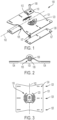
- a fall arrest roof mount anchor 100 has a mounting plate 101 having a uniform cross-section along a length of a horizontal axis 102 thereof.
- the cross-section defines a raised central portion 103 and roof attachment side portions 104.
- the mounting plate 101 may preferably be metallic and further preferably aluminium and manufactured using an extrusion process.
- the mounting plate preferably curves smoothly between the side portions 104 and the raised central portion 103, thereby eliminating sharp transitions and/or planar surfaces which could compromise flexural stiffness.
- the roof attachment side portions 104 are coplanar so as to lie flat on the roof surface or cross ribs thereof. Exemplary dimensions are given in Figure 9 wherein the mounting plate 101 may have a low profile height of less than 30 mm, such as approximately 25 mm which to maintain shear force resilience and flexural stiffness.
- the mounting plate 101 may comprise an integrally formed channel 105 running longitudinally along an under-surface of the raised central portion 103.
- the channel 105 confers flexural stiffness to the raised central portion 103.
- the channel 105 may capture a locknut 107 of an anchor bolt 108.
- the mounting plate 101 may further comprise channel wall portions 106 (which are independent of the raised central portion 103 and side portions 104) which define the channel 105.
- the channel wall portions 106 may be parallel thereby defining parallel inner surfaces, and spaced to accommodate a minimum diameter of the locknut 107 and thereby to non-rotatably capture the locknut 107 within the channel 105.
- the channel 105 may accommodate a central anchor point connection hole 112 along the length thereof, allowing a distal end of the anchor bolt 108 to protrude therethrough as shown in Figure 2 .
- the channel 105 may further comprise inwardly projecting flange portions 109 from respective distal ends of the channel wall portions 106. The flange portions 109 may support the locknut 107 within the channel 105 whilst allowing a distal end of the anchor bolt 108 to extend therebetween.
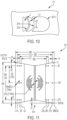
- the mounting plate 101 may be configured for installation along adjacent ribs of a roof profile surface, and/or wherein the horizontal axis 102 aligns along the pitch of the roof, or at least orientates towards an edge of the roof.
- the roof attachment side portions 104 may comprise a plurality of rivet fastener holes 124.
- the rivet fastener holes 124 may run in spaced rows 125 across the horizontal axis 102.
- the rows 125 may have rivet fastener hole spacings suited for specific roof profile crest-to-crest widths.
- the rivet fastener holes 124 in the rows 125 may be spaced apart in at least two intervals of 14 mm, 28 mm, 42 mm, 230 mm, 245 mm and 274 mm, from an edge of a roof attachment side 104 of the mounting plate 101.
- the mounting plate 101 comprises three rows 125, however in embodiments, a mounting plate 101 having a different number of rows 125 is contemplated, including an embodiment wherein the mounting plate 101 has four rows 125.
- the roof mount anchor 100 may comprise mounting pads 126 preferably of rubber material, which engage under each roof attachment side 104 of the mounting plate 101.
- the mounting pads 126 may comprise a plurality of fastener holes 127 which collocate with the rivet fastener holes 124 of the mounting plate 101.
- the mounting plate 101 may further splay longitudinally along the horizontal axis 102 towards both ends thereof.
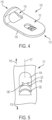
- the roof mount anchor 100 may further comprise a lanyard connector 110 attached to an apex of the raised central portion 103.
- the lanyard connector 110 may define an anchor connection aperture 111 for swivel engagement by the anchor bolt 108 at a proximal end 113 thereof.
- the mounting plate 101 may accordingly comprise a central anchor point connection hole 112 for the anchor bolt 108.
- the lanyard connector 110 may define an eyelet 114 towards a distal end 115 thereof, through which a carabiner or the like may attach a lanyard for tethering a user thereto.
- the lanyard connector 110 may comprise a swivel eye anchor plate 116 which bends upwardly towards the distal end 115.
- the eyelet 114 may transition across the upwardly bent distal end 115.
- the anchor connection aperture 111 may be elongate along a strain absorbing axis 117 through the proximal end 113 and distal end 115 of the lanyard connector 110.
- the lanyard connector 110 may have an integrally formed primary frail web 118 across the strain absorbing axis 117.
- the anchor connection aperture 111 may define a profile open an anchor bolt accommodation portion 119 which accommodates the anchor bolt 108 therethrough.
- the primary frail web 118 is preferably curved across the anchor connection aperture 111.
- the primary frail web 118 is further preferably inversely orientated so that an apex 120 thereof bears oppositely against the anchor bolt 108. This arrangement is designed both to absorb energy and reduce shock impact on the user, whilst also providing visual indication of abnormal loading (such as in excess of 7 kN), which is useful when undertaking routine inspection of the fall arrest system
- the primary frail web 118 may have an integral seating profile 121 which supports the anchor bolt 108 centrally against the primary frail web apex 120.
- the seating profile 121 may have an opposite curvature to that of the primary frail web 118.
- Figure 12 shows an embodiment wherein the seating profile 121, extends right to the edges of the anchor bolt cut-out 119 of the anchor connection aperture 111, thereby not only seating the anchor bolt 108 centrally but also reinforcing the primary frail web 118.
- the seating profile 121 may itself deform or fracture when the primary frail web 118 deforms under excessive load.
- the primary frail web 118 may have a thickness so as to visibly deform when a dynamic force of approximately 7 kN is applied to the lanyard connector 110.
- the lanyard connector 110 may be stainless steel comprising a thickness of approximately 3 mm, and the primary frail web 118 width be approximately 1.5 mm.
- the primary frail web 118 may further absorb dynamic shock forces when deforming.
- the anchor connection aperture 111 may further comprise an integrally formed secondary frail web 122 across the strain absorbing axis 117.
- the secondary frail web 122 width may be narrower than the primary frail web 118 width, such as being approximately 1 mm as shown in Figure 10 .
- the mounting plate 101 may comprise a matrix 130 of elongate stress relief cut-outs 123 surrounding the swivel eye anchor point.
- Each stress relief cut-out 123 may arc concentrically around the swivel eye anchor point.
- Single and pairs of stress relief cut-outs 123 may locate symmetrically opposite the swivel eye anchor point connection hole 112, and may be arranged at different radial offsets. Furthermore, the stress relief cut-outs 123 arranged at different radial offsets from the swivel eye anchor point may overlap concentrically.
Landscapes
- Engineering & Computer Science (AREA)
- Architecture (AREA)
- Mechanical Engineering (AREA)
- Civil Engineering (AREA)
- Structural Engineering (AREA)
- Health & Medical Sciences (AREA)
- General Health & Medical Sciences (AREA)
- Business, Economics & Management (AREA)
- Emergency Management (AREA)
- Roof Covering Using Slabs Or Stiff Sheets (AREA)
- Emergency Lowering Means (AREA)
- Joining Of Building Structures In Genera (AREA)
Applications Claiming Priority (3)
| Application Number | Priority Date | Filing Date | Title |
|---|---|---|---|
| AU2021902563A AU2021902563A0 (en) | 2021-08-17 | A fall arrest and rope access roof mount anchor | |
| PCT/AU2022/050890 WO2023019295A1 (en) | 2021-08-17 | 2022-08-15 | A fall arrest roof mount anchor |
| EP22818160.8A EP4158131B1 (de) | 2021-08-17 | 2022-08-15 | Absturzsicherer dachmontageanker |
Related Parent Applications (2)
| Application Number | Title | Priority Date | Filing Date |
|---|---|---|---|
| EP22818160.8A Division EP4158131B1 (de) | 2021-08-17 | 2022-08-15 | Absturzsicherer dachmontageanker |
| EP22818160.8A Division-Into EP4158131B1 (de) | 2021-08-17 | 2022-08-15 | Absturzsicherer dachmontageanker |
Publications (4)
| Publication Number | Publication Date |
|---|---|
| EP4249082A2 true EP4249082A2 (de) | 2023-09-27 |
| EP4249082A3 EP4249082A3 (de) | 2023-11-08 |
| EP4249082B1 EP4249082B1 (de) | 2024-07-10 |
| EP4249082C0 EP4249082C0 (de) | 2024-07-10 |
Family
ID=85382426
Family Applications (2)
| Application Number | Title | Priority Date | Filing Date |
|---|---|---|---|
| EP23186540.3A Active EP4249082B1 (de) | 2021-08-17 | 2022-08-15 | Ein anschluss für ein schlüsselband |
| EP22818160.8A Active EP4158131B1 (de) | 2021-08-17 | 2022-08-15 | Absturzsicherer dachmontageanker |
Family Applications After (1)
| Application Number | Title | Priority Date | Filing Date |
|---|---|---|---|
| EP22818160.8A Active EP4158131B1 (de) | 2021-08-17 | 2022-08-15 | Absturzsicherer dachmontageanker |
Country Status (5)
| Country | Link |
|---|---|
| US (2) | US12448797B2 (de) |
| EP (2) | EP4249082B1 (de) |
| AU (2) | AU2022283696B2 (de) |
| CA (1) | CA3183201A1 (de) |
| GB (1) | GB2614135B (de) |
Families Citing this family (5)
| Publication number | Priority date | Publication date | Assignee | Title |
|---|---|---|---|---|
| EP4249082B1 (de) * | 2021-08-17 | 2024-07-10 | Sayfa R&D Pty Ltd | Ein anschluss für ein schlüsselband |
| USD1032402S1 (en) * | 2022-02-04 | 2024-06-25 | Sayfa R&D Pty Ltd | Lanyard connector aperture |
| US20240342522A1 (en) * | 2023-04-14 | 2024-10-17 | Unified Safety Inc. | Anchor devices for fall protection |
| CA222547S (en) * | 2023-06-20 | 2024-09-06 | Sayfa R&D Pty Ltd | Tension anchor |
| US12415103B1 (en) | 2024-04-24 | 2025-09-16 | Ronald N. Roseveare, Jr. | Fall protection anchor devices, systems, and methods |
Family Cites Families (40)
| Publication number | Priority date | Publication date | Assignee | Title |
|---|---|---|---|---|
| KR960009276B1 (en) * | 1990-10-18 | 1996-07-16 | Kantan Beauty Ind K K | Double joining roof-structure |
| US5732974A (en) | 1997-03-03 | 1998-03-31 | Trw Vehicle Safety Systems Inc. | Seat belt system energy management device replacement indicator |
| GB9919374D0 (en) * | 1999-08-17 | 1999-10-20 | Valro Mfg Ltd | Anchor plates |
| FR2808695B1 (fr) * | 2000-05-11 | 2002-08-09 | Antec Sa | Point d'ancrage avec temoin de chute ou de surcharge par rupture d'un element |
| AUPQ942200A0 (en) * | 2000-08-15 | 2000-09-07 | Poldmaa, Arvo | Roof anchor method and apparatus |
| GB0028930D0 (en) * | 2000-11-28 | 2001-01-10 | Gleave David S | Roof safety system |
| US6986494B2 (en) * | 2003-05-15 | 2006-01-17 | Dyneter Industries Ltd. | Self-aligning mounting bracket and system for mounting a planar structure to a fixed structure |
| NL1027728C2 (nl) * | 2003-12-24 | 2005-07-05 | Kedge Holding Bv | Zekeringsinrichting voor een valbeveiliging. |
| FR2872057B1 (fr) * | 2004-06-29 | 2006-09-15 | Badou Dalloz Vierzon Soc Par A | Dispositif absorbeur d'energie pour ligne de vie |
| GB0419127D0 (en) * | 2004-08-27 | 2004-09-29 | Hadrian Iye England Ltd | Safety rail system |
| AU2008100070B4 (en) * | 2008-01-25 | 2008-09-18 | Sayfa R & D Pty Ltd | Static line system |
| GB2473209B (en) | 2009-09-02 | 2014-12-03 | Latchways Plc | Bracket fixing for a safety line |
| US20110214388A1 (en) * | 2010-03-06 | 2011-09-08 | Mr. Joseph Tony London, SR. | Roof clamp for fall protection safety equipment |
| AT11927U1 (de) * | 2010-06-25 | 2011-07-15 | Em Tech Power Gmbh | Absturzsicherung |
| US8973705B2 (en) | 2010-09-01 | 2015-03-10 | Climb Tech, Llc | Swivel D-ring attachment point |
| GB201015446D0 (en) | 2010-09-16 | 2010-10-27 | Marcoux Philippe | Safety line anchor and method of using same |
| US8453794B2 (en) | 2010-11-16 | 2013-06-04 | Jonathan J. Melic | Anchor assembly |
| IT1402757B1 (it) | 2010-11-16 | 2013-09-18 | Bruscuglia | Sistema integrato di assorbimento delle forze per dispositivi di ancoraggio uni en 795/02 |
| US9611652B2 (en) * | 2011-02-25 | 2017-04-04 | Dustin M. M. Haddock | Mounting device for building surfaces having elongated mounting slot |
| US20130087669A1 (en) | 2011-10-10 | 2013-04-11 | Vincent P. Daddio | Roof Safety Anchor |
| GB2511340A (en) * | 2013-02-28 | 2014-09-03 | Latchways Plc | Membrane bonded anchor arrangement |
| EP2997206B1 (de) * | 2013-04-17 | 2021-04-14 | Rood, Geertruida Anna | Dachanker, fallsicherungsvorrichtung und -verfahren |
| GB2515341B (en) | 2013-06-21 | 2017-07-12 | The Heightec Group Ltd | Rope safety device |
| CN104288935A (zh) | 2014-09-12 | 2015-01-21 | 浙江百安固金属屋面有限公司 | 一种钢索防坠落系统及其安装方法 |
| US9821759B2 (en) | 2015-03-05 | 2017-11-21 | Ford Global Technologies, Llc | Seat-belt mounting system |
| AU2016257768B2 (en) * | 2015-05-05 | 2020-07-09 | Safetylink Pty Ltd | An anchor |
| US9856900B1 (en) | 2015-05-06 | 2018-01-02 | Allfasteners USA, LLC | Step Bolt Connector Assembly |
| US10443896B2 (en) * | 2016-07-29 | 2019-10-15 | Rmh Tech Llc | Trapezoidal rib mounting bracket with flexible legs |
| DE102017100373A1 (de) * | 2017-01-10 | 2018-07-12 | Dws Pohl Gmbh | Vorrichtung zur Sicherung von Personen gegen Absturz |
| US10744353B2 (en) | 2017-05-02 | 2020-08-18 | Warren Ballantyne | Roof anchor and safety system and method of using the same |
| AT520447B1 (de) * | 2017-12-12 | 2019-04-15 | Tigasafe Gmbh | Absturzsicherung |
| CA3091867A1 (en) | 2018-02-20 | 2019-08-29 | Unified Safety Inc. | Fall protection system |
| EP3921483A4 (de) * | 2019-02-04 | 2022-11-02 | OMG, Inc. | Dachmontageanordnung mit stabilisierter befestigungsmatrix |
| US10767684B1 (en) * | 2019-04-26 | 2020-09-08 | Solsera, Inc. | Flat roof mounting device |
| US11428009B2 (en) * | 2019-09-30 | 2022-08-30 | Bmic Llc | Self-sealing roof fastener |
| US11603675B2 (en) * | 2020-01-23 | 2023-03-14 | Steven Christopher Nichols | Devices, systems and methods relating to roof standing seam anchors |
| US11306490B1 (en) * | 2020-03-31 | 2022-04-19 | Johnny Blow | Roofing safety system |
| US11698166B1 (en) * | 2021-08-11 | 2023-07-11 | Gregory F. Ryan | Emergency escape device and method of forming the emergency escape device |
| EP4249082B1 (de) * | 2021-08-17 | 2024-07-10 | Sayfa R&D Pty Ltd | Ein anschluss für ein schlüsselband |
| USD1013901S1 (en) * | 2021-11-01 | 2024-02-06 | Sayfa R&D Pty Ltd | Fall arrest roof anchor plate |
-
2022
- 2022-08-15 EP EP23186540.3A patent/EP4249082B1/de active Active
- 2022-08-15 EP EP22818160.8A patent/EP4158131B1/de active Active
- 2022-08-15 AU AU2022283696A patent/AU2022283696B2/en active Active
- 2022-08-15 US US18/001,924 patent/US12448797B2/en active Active
- 2022-08-15 GB GB2218923.7A patent/GB2614135B/en active Active
- 2022-08-15 CA CA3183201A patent/CA3183201A1/en active Pending
-
2023
- 2023-07-07 US US18/348,679 patent/US12404687B2/en active Active
- 2023-07-21 AU AU2023206224A patent/AU2023206224B2/en active Active
Also Published As
| Publication number | Publication date |
|---|---|
| AU2023206224B2 (en) | 2023-10-19 |
| CA3183201A1 (en) | 2023-02-17 |
| AU2022283696A1 (en) | 2023-03-09 |
| AU2022283696B2 (en) | 2023-08-24 |
| EP4158131C0 (de) | 2025-07-02 |
| GB2614135B (en) | 2024-07-10 |
| EP4249082A3 (de) | 2023-11-08 |
| AU2023206224A1 (en) | 2023-08-10 |
| US12404687B2 (en) | 2025-09-02 |
| GB202218923D0 (en) | 2023-02-01 |
| EP4158131B1 (de) | 2025-07-02 |
| EP4158131A4 (de) | 2024-08-14 |
| GB2614135A (en) | 2023-06-28 |
| US12448797B2 (en) | 2025-10-21 |
| EP4249082B1 (de) | 2024-07-10 |
| US20240102302A1 (en) | 2024-03-28 |
| US20230349181A1 (en) | 2023-11-02 |
| EP4249082C0 (de) | 2024-07-10 |
| EP4158131A1 (de) | 2023-04-05 |
Similar Documents
| Publication | Publication Date | Title |
|---|---|---|
| AU2022283696B2 (en) | A fall arrest roof mount anchor | |
| US5553685A (en) | Roof safety anchor | |
| US10617898B2 (en) | Anchor | |
| US11898585B2 (en) | Decking hanger system and decking hanger | |
| EP3192924B1 (de) | Schutzbarriere für strassen | |
| US10112078B1 (en) | Step assembly with fall arrest capability including removable step | |
| US20120317892A1 (en) | Sheathing edge protector and roof safety anchor assembly incorporating the same | |
| US11013941B2 (en) | Device for preventing persons from falling | |
| CA2960635A1 (en) | Monolithic roof anchor | |
| GB2351789A (en) | Shock absorbing support and fall-arrest system | |
| US9227094B2 (en) | Height safety anchor | |
| WO2023019295A1 (en) | A fall arrest roof mount anchor | |
| CA2431351C (en) | Square embossed roof and rib plate | |
| JP6808902B2 (ja) | 吊り天井の下地構造 | |
| US6907699B2 (en) | Gypsum wallboard fastener | |
| AU2009100646A4 (en) | A Roof Anchor | |
| EP2520740A1 (de) | Ankervorrichtung einer Sturzsicherungsvorrichtung und zusammengehörige Sturzsicherungsvorrichtung | |
| CN222976467U (zh) | 钢构建筑屋顶防坠组件 | |
| AU2014203632B2 (en) | Height Safety Anchor | |
| CN220653305U (zh) | 一种连接装置和光伏系统 | |
| US20240342522A1 (en) | Anchor devices for fall protection | |
| JPS6347220Y2 (de) | ||
| GB2385088A (en) | A roof bracket for securing a cable guide to a roof | |
| WO2024040298A1 (en) | Multi-part anchor assembly | |
| WO2024059898A1 (en) | Temporary safety anchor assembly |
Legal Events
| Date | Code | Title | Description |
|---|---|---|---|
| PUAI | Public reference made under article 153(3) epc to a published international application that has entered the european phase |
Free format text: ORIGINAL CODE: 0009012 |
|
| STAA | Information on the status of an ep patent application or granted ep patent |
Free format text: STATUS: REQUEST FOR EXAMINATION WAS MADE |
|
| 17P | Request for examination filed |
Effective date: 20230719 |
|
| AC | Divisional application: reference to earlier application |
Ref document number: 4158131 Country of ref document: EP Kind code of ref document: P |
|
| AK | Designated contracting states |
Kind code of ref document: A2 Designated state(s): AL AT BE BG CH CY CZ DE DK EE ES FI FR GB GR HR HU IE IS IT LI LT LU LV MC MK MT NL NO PL PT RO RS SE SI SK SM TR |
|
| PUAL | Search report despatched |
Free format text: ORIGINAL CODE: 0009013 |
|
| AK | Designated contracting states |
Kind code of ref document: A3 Designated state(s): AL AT BE BG CH CY CZ DE DK EE ES FI FR GB GR HR HU IE IS IT LI LT LU LV MC MK MT NL NO PL PT RO RS SE SI SK SM TR |
|
| RIC1 | Information provided on ipc code assigned before grant |
Ipc: A62B 35/04 20060101ALI20230929BHEP Ipc: E04G 21/32 20060101ALI20230929BHEP Ipc: A62B 35/00 20060101AFI20230929BHEP |
|
| GRAP | Despatch of communication of intention to grant a patent |
Free format text: ORIGINAL CODE: EPIDOSNIGR1 |
|
| STAA | Information on the status of an ep patent application or granted ep patent |
Free format text: STATUS: GRANT OF PATENT IS INTENDED |
|
| INTG | Intention to grant announced |
Effective date: 20240423 |
|
| GRAS | Grant fee paid |
Free format text: ORIGINAL CODE: EPIDOSNIGR3 |
|
| GRAA | (expected) grant |
Free format text: ORIGINAL CODE: 0009210 |
|
| STAA | Information on the status of an ep patent application or granted ep patent |
Free format text: STATUS: THE PATENT HAS BEEN GRANTED |
|
| AC | Divisional application: reference to earlier application |
Ref document number: 4158131 Country of ref document: EP Kind code of ref document: P |
|
| AK | Designated contracting states |
Kind code of ref document: B1 Designated state(s): AL AT BE BG CH CY CZ DE DK EE ES FI FR GR HR HU IE IS IT LI LT LU LV MC MK MT NL NO PL PT RO RS SE SI SK SM TR |
|
| RBV | Designated contracting states (corrected) |
Designated state(s): AL AT BE BG CH CY CZ DE DK EE ES FI FR GR HR HU IE IS IT LI LT LU LV MC MK MT NL NO PL PT RO RS SE SI SK SM TR |
|
| REG | Reference to a national code |
Ref country code: CH Ref legal event code: EP |
|
| REG | Reference to a national code |
Ref country code: DE Ref legal event code: R096 Ref document number: 602022004515 Country of ref document: DE |
|
| U01 | Request for unitary effect filed |
Effective date: 20240805 |
|
| U07 | Unitary effect registered |
Designated state(s): AT BE BG DE DK EE FI FR IT LT LU LV MT NL PT RO SE SI Effective date: 20240902 |
|
| U20 | Renewal fee for the european patent with unitary effect paid |
Year of fee payment: 3 Effective date: 20240904 |
|
| PG25 | Lapsed in a contracting state [announced via postgrant information from national office to epo] |
Ref country code: NO Free format text: LAPSE BECAUSE OF FAILURE TO SUBMIT A TRANSLATION OF THE DESCRIPTION OR TO PAY THE FEE WITHIN THE PRESCRIBED TIME-LIMIT Effective date: 20241010 |
|
| PG25 | Lapsed in a contracting state [announced via postgrant information from national office to epo] |
Ref country code: GR Free format text: LAPSE BECAUSE OF FAILURE TO SUBMIT A TRANSLATION OF THE DESCRIPTION OR TO PAY THE FEE WITHIN THE PRESCRIBED TIME-LIMIT Effective date: 20241011 Ref country code: PL Free format text: LAPSE BECAUSE OF FAILURE TO SUBMIT A TRANSLATION OF THE DESCRIPTION OR TO PAY THE FEE WITHIN THE PRESCRIBED TIME-LIMIT Effective date: 20240710 |
|
| PG25 | Lapsed in a contracting state [announced via postgrant information from national office to epo] |
Ref country code: IS Free format text: LAPSE BECAUSE OF FAILURE TO SUBMIT A TRANSLATION OF THE DESCRIPTION OR TO PAY THE FEE WITHIN THE PRESCRIBED TIME-LIMIT Effective date: 20241110 |
|
| PG25 | Lapsed in a contracting state [announced via postgrant information from national office to epo] |
Ref country code: HR Free format text: LAPSE BECAUSE OF FAILURE TO SUBMIT A TRANSLATION OF THE DESCRIPTION OR TO PAY THE FEE WITHIN THE PRESCRIBED TIME-LIMIT Effective date: 20240710 |
|
| PG25 | Lapsed in a contracting state [announced via postgrant information from national office to epo] |
Ref country code: ES Free format text: LAPSE BECAUSE OF FAILURE TO SUBMIT A TRANSLATION OF THE DESCRIPTION OR TO PAY THE FEE WITHIN THE PRESCRIBED TIME-LIMIT Effective date: 20240710 Ref country code: RS Free format text: LAPSE BECAUSE OF FAILURE TO SUBMIT A TRANSLATION OF THE DESCRIPTION OR TO PAY THE FEE WITHIN THE PRESCRIBED TIME-LIMIT Effective date: 20241010 |
|
| PG25 | Lapsed in a contracting state [announced via postgrant information from national office to epo] |
Ref country code: RS Free format text: LAPSE BECAUSE OF FAILURE TO SUBMIT A TRANSLATION OF THE DESCRIPTION OR TO PAY THE FEE WITHIN THE PRESCRIBED TIME-LIMIT Effective date: 20241010 Ref country code: PL Free format text: LAPSE BECAUSE OF FAILURE TO SUBMIT A TRANSLATION OF THE DESCRIPTION OR TO PAY THE FEE WITHIN THE PRESCRIBED TIME-LIMIT Effective date: 20240710 Ref country code: NO Free format text: LAPSE BECAUSE OF FAILURE TO SUBMIT A TRANSLATION OF THE DESCRIPTION OR TO PAY THE FEE WITHIN THE PRESCRIBED TIME-LIMIT Effective date: 20241010 Ref country code: IS Free format text: LAPSE BECAUSE OF FAILURE TO SUBMIT A TRANSLATION OF THE DESCRIPTION OR TO PAY THE FEE WITHIN THE PRESCRIBED TIME-LIMIT Effective date: 20241110 Ref country code: HR Free format text: LAPSE BECAUSE OF FAILURE TO SUBMIT A TRANSLATION OF THE DESCRIPTION OR TO PAY THE FEE WITHIN THE PRESCRIBED TIME-LIMIT Effective date: 20240710 Ref country code: GR Free format text: LAPSE BECAUSE OF FAILURE TO SUBMIT A TRANSLATION OF THE DESCRIPTION OR TO PAY THE FEE WITHIN THE PRESCRIBED TIME-LIMIT Effective date: 20241011 Ref country code: ES Free format text: LAPSE BECAUSE OF FAILURE TO SUBMIT A TRANSLATION OF THE DESCRIPTION OR TO PAY THE FEE WITHIN THE PRESCRIBED TIME-LIMIT Effective date: 20240710 |
|
| PG25 | Lapsed in a contracting state [announced via postgrant information from national office to epo] |
Ref country code: SM Free format text: LAPSE BECAUSE OF FAILURE TO SUBMIT A TRANSLATION OF THE DESCRIPTION OR TO PAY THE FEE WITHIN THE PRESCRIBED TIME-LIMIT Effective date: 20240710 |
|
| PG25 | Lapsed in a contracting state [announced via postgrant information from national office to epo] |
Ref country code: MC Free format text: LAPSE BECAUSE OF FAILURE TO SUBMIT A TRANSLATION OF THE DESCRIPTION OR TO PAY THE FEE WITHIN THE PRESCRIBED TIME-LIMIT Effective date: 20240710 |
|
| PG25 | Lapsed in a contracting state [announced via postgrant information from national office to epo] |
Ref country code: CZ Free format text: LAPSE BECAUSE OF FAILURE TO SUBMIT A TRANSLATION OF THE DESCRIPTION OR TO PAY THE FEE WITHIN THE PRESCRIBED TIME-LIMIT Effective date: 20240710 |
|
| PG25 | Lapsed in a contracting state [announced via postgrant information from national office to epo] |
Ref country code: SK Free format text: LAPSE BECAUSE OF FAILURE TO SUBMIT A TRANSLATION OF THE DESCRIPTION OR TO PAY THE FEE WITHIN THE PRESCRIBED TIME-LIMIT Effective date: 20240710 |
|
| PLBE | No opposition filed within time limit |
Free format text: ORIGINAL CODE: 0009261 |
|
| STAA | Information on the status of an ep patent application or granted ep patent |
Free format text: STATUS: NO OPPOSITION FILED WITHIN TIME LIMIT |
|
| 26N | No opposition filed |
Effective date: 20250411 |
|
| PG25 | Lapsed in a contracting state [announced via postgrant information from national office to epo] |
Ref country code: IE Free format text: LAPSE BECAUSE OF NON-PAYMENT OF DUE FEES Effective date: 20240815 |
|
| U20 | Renewal fee for the european patent with unitary effect paid |
Year of fee payment: 4 Effective date: 20250620 |