EP4248730A2 - Appareil adaptable, procédé de commande d'un appareil accessoire ainsi que moissonneuse-batteuse - Google Patents
Appareil adaptable, procédé de commande d'un appareil accessoire ainsi que moissonneuse-batteuse Download PDFInfo
- Publication number
- EP4248730A2 EP4248730A2 EP23153421.5A EP23153421A EP4248730A2 EP 4248730 A2 EP4248730 A2 EP 4248730A2 EP 23153421 A EP23153421 A EP 23153421A EP 4248730 A2 EP4248730 A2 EP 4248730A2
- Authority
- EP
- European Patent Office
- Prior art keywords
- reel
- attachment
- segments
- crop
- control unit
- Prior art date
- Legal status (The legal status is an assumption and is not a legal conclusion. Google has not performed a legal analysis and makes no representation as to the accuracy of the status listed.)
- Pending
Links
- 238000000034 method Methods 0.000 title claims description 18
- 238000005259 measurement Methods 0.000 claims abstract description 28
- 230000008859 change Effects 0.000 claims abstract description 13
- 238000001514 detection method Methods 0.000 claims description 24
- 239000000969 carrier Substances 0.000 claims description 15
- 238000004458 analytical method Methods 0.000 claims description 3
- 230000035484 reaction time Effects 0.000 claims description 3
- 238000002604 ultrasonography Methods 0.000 claims description 3
- 238000012417 linear regression Methods 0.000 claims 1
- 238000005520 cutting process Methods 0.000 description 19
- 238000003306 harvesting Methods 0.000 description 12
- 238000011161 development Methods 0.000 description 11
- 230000018109 developmental process Effects 0.000 description 11
- 210000005069 ears Anatomy 0.000 description 6
- 238000000926 separation method Methods 0.000 description 5
- 238000003860 storage Methods 0.000 description 5
- 230000006978 adaptation Effects 0.000 description 4
- 238000004364 calculation method Methods 0.000 description 4
- 239000000463 material Substances 0.000 description 4
- 230000008901 benefit Effects 0.000 description 3
- 238000004140 cleaning Methods 0.000 description 3
- 238000006073 displacement reaction Methods 0.000 description 3
- 238000009826 distribution Methods 0.000 description 3
- 239000010902 straw Substances 0.000 description 3
- 230000006872 improvement Effects 0.000 description 2
- 230000007246 mechanism Effects 0.000 description 2
- 238000012545 processing Methods 0.000 description 2
- 238000000611 regression analysis Methods 0.000 description 2
- 238000012935 Averaging Methods 0.000 description 1
- 244000188595 Brassica sinapistrum Species 0.000 description 1
- 235000004977 Brassica sinapistrum Nutrition 0.000 description 1
- 241000196324 Embryophyta Species 0.000 description 1
- 230000001419 dependent effect Effects 0.000 description 1
- 238000013461 design Methods 0.000 description 1
- 238000011982 device technology Methods 0.000 description 1
- 235000013399 edible fruits Nutrition 0.000 description 1
- 230000000694 effects Effects 0.000 description 1
- 238000005516 engineering process Methods 0.000 description 1
- 230000007613 environmental effect Effects 0.000 description 1
- 238000011156 evaluation Methods 0.000 description 1
- 238000010327 methods by industry Methods 0.000 description 1
- 210000000056 organ Anatomy 0.000 description 1
- 230000008569 process Effects 0.000 description 1
- 230000008439 repair process Effects 0.000 description 1
- 230000000717 retained effect Effects 0.000 description 1
- 239000002689 soil Substances 0.000 description 1
- 238000012549 training Methods 0.000 description 1
- 238000011144 upstream manufacturing Methods 0.000 description 1
Images


Classifications
-
- A—HUMAN NECESSITIES
- A01—AGRICULTURE; FORESTRY; ANIMAL HUSBANDRY; HUNTING; TRAPPING; FISHING
- A01D—HARVESTING; MOWING
- A01D57/00—Delivering mechanisms for harvesters or mowers
- A01D57/01—Devices for leading crops to the mowing apparatus
- A01D57/02—Devices for leading crops to the mowing apparatus using reels
- A01D57/04—Arrangements for changing the position of the reels
-
- A—HUMAN NECESSITIES
- A01—AGRICULTURE; FORESTRY; ANIMAL HUSBANDRY; HUNTING; TRAPPING; FISHING
- A01D—HARVESTING; MOWING
- A01D41/00—Combines, i.e. harvesters or mowers combined with threshing devices
- A01D41/12—Details of combines
- A01D41/14—Mowing tables
- A01D41/141—Automatic header control
Definitions
- the present invention relates to an attachment according to the preamble of claim 1. Furthermore, the present invention relates to a method for controlling an attachment according to the preamble of claim 16 and a combine harvester according to claim 18.
- the attachment in question is any attachment that is set up to cut and pick up crops.
- Such an attachment includes a reel which extends essentially over the entire width of the attachment.
- the reel has at least two reel segments, which are arranged on reel support arms.
- the reel segments can be adjusted in the vertical and horizontal directions by actuators arranged on the attachment.
- a control unit is assigned to the attachment to control the actuators.
- the reel segments are adjusted synchronously in the vertical and horizontal directions. This is achieved using hydraulic master/slave cylinders as actuators.
- An operator only adjusts the height and the horizontal distance to the cutter bar of the attachment so that the crop, such as grain, reaches the attachment evenly with a continuous crop flow. If the reel is set too high so that the reel tines no longer touch the crop, especially the ears, the crop can become jammed due to a lack of guidance in the attachment. This results in an uneven crop flow with sometimes high load peaks, which results in high crop losses and greater wear and tear on the working organs and drives of a combine harvester that carries the attachment.
- the situation is similar if the horizontal adjustment of the reel is not optimal. If the horizontal distance of the reel is chosen too far in front of the knife bar, the crop cannot be guided sufficiently and an uneven crop flow occurs in the cutting trough of an attachment designed as a screw cutter or on the conveyor belts of an attachment designed as a belt cutter, with the well-known consequences. If the horizontal distance between the reel and the knife bar is too short, the harvested crop can be compressed in front of the conveyor elements. This can, especially in the case of rapeseed, lead to the harvested material being carried away by the reel, with the well-known consequences.
- the belt cutting unit has a central section and two side sections, each of which can be deflected in the vertical direction about a horizontal axis relative to the central section in order to be able to follow a change in the ground contour.
- a reel of the belt cutting unit is divided into two reel segments, which are supported by two outer, synchronously moved reel support arms and an inner reel support arm. The two reel segments are articulated at their mutually facing ends on the inner reel support arm.
- the inner reel support arm is movable independently of the two outer reel support arms.
- the belt cutting unit has a central section and two side sections, each of which can be deflected in the vertical direction about a horizontal axis relative to the central section in order to be able to follow a change in the ground contour.
- a reel of the belt cutting unit is divided into three reel segments, which are supported by two outer reel support arms and two inner reel support arms. The two outer reel segments are articulated at their mutually facing ends on the inner reel support arms. According to the EP 3 841 866 A1 It is intended that the reel segments can be adjusted independently of one another.
- the invention is based on the object of developing an attachment and a method for controlling the attachment, which is characterized by an improved adaptation of the reel setting to small-scale changes in the crop population.
- an attachment with a reel is proposed, the reel having at least two reel segments which are articulated on reel support arms, with actuators being arranged on the attachment which are set up to adjust the reel segments in the vertical and horizontal directions, whereby A control unit is assigned to the attachment for controlling the actuators. Swivel joints are provided to connect the reel segments to the reel support arms.
- At least one sensor device is assigned to the attachment, which is set up to generate measurement signals for determining a crop height and/or a crop density of a crop stock located in advance of the attachment, the control unit being set up to receive and evaluate the measurement signals in order to automatically control the actuators to carry out an independent change in position of the reel support arms depending on the inventory height values and/or inventory density values determined from the measurement signals.
- the proposed solution is based, first of all, on the fundamental knowledge that individual adjustment of the horizontal position and vertical position of the reel segments is a necessary prerequisite for avoiding grain losses that occur on the attachment itself. Detecting the crop height and/or the crop density of the crop inventory located in front of the attachment has the advantage that small-scale changes can be responded to better and more efficiently in order to achieve an optimized setting of the individual reel segments through the independent adjustment of the reel support arms. This allows the resulting crop loss to be reduced. In addition, through the optimized setting of the individual reel segments, a higher throughput can be achieved with constant or lower crop losses. In addition, an improvement in the crop flow in the header can be achieved, especially in difficult harvest situations, especially when stored grain occurs.
- the automatic control of the respective actuators to carry out an independent change in the position of the reel support arms in the horizontal and/or vertical direction relieves the operator of the necessary adjustment tasks, especially in difficult harvesting situations.
- the at least one sensor device provides the measurement signals as input variables for the analytical determination of inventory height values and/or inventory density values by the control unit.
- the at least one sensor device being a LIDAR system, a camera system, as Radar system and / or can be designed as an ultrasound system. It can be provided to combine differently designed sensor devices with one another in order to improve the accuracy of the determination of the inventory height values and/or the inventory density values, which also improves the control of the respective actuators.
- the control unit can preferably be set up to divide an inventory strip detected by the at least one sensor device in advance of the attachment into several detection segments, with at least one detection segment being assigned to an individual reel segment.
- the multiple detection segments cover at least the working width of the attachment.
- a further detection segment can be assigned to an area to the side of the attachment. The assignment of an additional detection segment on both sides to the side of the attachment can be provided if the presence of a crop edge is also to be detected by the at least one sensor device, which serves as an orientation aid for guiding the attachment or the combine harvester carrying the attachment.
- control unit can be set up to divide the detection segments into individual area sectors in order to determine the crop height values and/or crop density values from the respective measurement signals for the crop height and/or the crop density of each individual area sector.
- the division of the detection segments into individual area sectors results in a higher resolution when determining the crop height values and/or the crop density values, which means that the individual reel segments can be controlled more precisely and are better adapted to small-scale changes in the crop inventory.
- control unit can be set up to control the sensor device to detect the stock strip to be detected in advance at a predetermined distance from the front edge or knife bar of the attachment, the control unit being set up to determine the distance between the front edge and the beginning of the strip to be detected To determine the inventory strip at least depending on the reaction time of the actuators. This ensures that there is sufficient lead time for the evaluation and generation of control commands by the control unit in order to automatically control the actuators for independently changing the position of the reel support arms.
- the individual surface sectors can preferably be essentially rectangular and have edge lengths in the range from 0.5 m to 2 m.
- the size of the surface sectors in the direction of movement of the attachment and transversely should be chosen so that there is an optimum between a representative measurement and a suitable height movement and/or horizontal movement of the reel.
- the height adjustment and the horizontal adjustment of the individual reel segments can be calculated in order to be able to automatically control an independent change in position of the reel support arms that is optimally adapted to the existing harvest conditions.
- control unit can be set up to carry out a regression analysis in order to generate control commands for controlling the actuators for a height adjustment and/or a horizontal adjustment of the respective reel support arm depending on the analysis result.
- the calculation can be carried out using regression analysis of the crop height values and/or the crop density values in the individual area sectors across the width of the attachment.
- the height adjustment and/or the horizontal adjustment of the reel segments through the independent control of the reel support arms can then be determined from a specific regression curve for the respective location coordinates, viewed over the working width of the attachment, after calculating the geometric data of the reel segments, such as reel radius, tine length, etc become.
- control unit can be set up to use linear or nonlinear regression, in particular quantile regression, as a regression method.
- linear or nonlinear regression in particular quantile regression
- other analysis methods are also conceivable, such as averaging or iterative approximation methods.
- the number of adjustable reel support arms can correspond to the number of reel segments increased by the value 1, with two reel support arms on the outside of the attachment and the third or each other Reel support arm is arranged between the adjacent reel segments on the attachment.
- the attachment can only have one drive for generating a rotational movement of all reel segments, which are connected to one another by a common reel shaft.
- the number of adjustable reel support arms can correspond to twice the number of reel segments, with each reel segment being arranged between two adjustable reel support arms.
- Each reel segment can have a separate drive to generate a rotational movement of the respective reel segment.
- the reel support arms of the respective reel segment can only be adjustable in pairs. According to this development, a high degree of functional fulfillment can be achieved with a design of the reel which has two reel segments and four reel support arms that can be adjusted independently in pairs. With an increasing, especially odd, number of reel segments, a further increase in the degree of functional fulfillment can be achieved, since with the increasing number of reel segments the flexibility increases in order to be able to react to small-scale changes in the crop inventory, i.e. in particular with regard to crop density and / or crop height.
- each reel segment can be divided into at least three sections, each section having a variable outer diameter of the arrangement of tine carriers distributed on support stars in the circumferential direction. Adjusting the outer diameter of the respective reel segment or the tine carrier with tines arranged thereon in sections enables more flexible adaptation to changing harvest conditions, especially in the acceptance area of an individual reel segment.
- each reel segment can have a plurality of support stars which are arranged on a reel shaft at a distance from one another and are truncated cone-shaped in the axial direction, as well as tine carriers which extend over the width of the respective section of the reel segment and are connected to one another by joints, the tine carriers being on the truncated cone-shaped support stars in a substantially star shape arranged
- Guideways are guided in an adjustable radial direction in relation to the reel shaft.
- the star-shaped guide tracks on the respective support star run axially parallel to the reel shaft.
- a method for controlling an attachment with a reel is proposed, the reel having at least two reel segments which are articulated on reel support arms, the reel segments being adjusted in the vertical and horizontal directions by actuators arranged on the attachment, the Actuators are controlled by a control unit assigned to the attachment, with the attachment being assigned at least one sensor device, through which measurement signals for determining a crop height and / or a crop density of a crop stock located in advance of the attachment are generated, the measurement signals being received and evaluated by the control unit in order to automatically control the actuators to carry out an independent change in position of the reel support arms depending on the inventory height values and/or inventory density values determined from the measurement signals.
- an existing strip of the apron of the attachment which runs parallel to the working width of the attachment and is detected by the at least one sensor device, is divided into several detection segments, with at least two detection segments being assigned to a single reel segment and one detection segment to an area to the side of the attachment is assigned, the recording segments being subdivided into individual area sectors in order to determine the stock height values and/or stock density values from the respective measurement signals for the stock height and/or the stock density of each individual area sector.
- the size of the area sectors can be specified automatically, for example depending on the working width of the attachment, or by manual input by an operator.
- the method for controlling the attachment can have all the features described in connection with the attachment according to the invention according to claims 2 to 15 individually or in combination.
- a combine harvester with an attachment, the attachment comprising a reel, the reel having at least two reel segments which are arranged on reel support arms, the reel segments being actuated by actuators arranged on the attachment can be adjusted vertically and horizontally, with the attachment for controlling the actuators being assigned a control unit, characterized in that the attachment is designed according to one of the preceding claims 1 to 15 and the control unit is set up to carry out a method according to one of claims 16 or 17 .
- a significant effect is a higher throughput of the combine harvester with constant or lower grain losses.
- a higher quality of the processed crop can be achieved by a more even and continuous feed of the crop into the combine. This also leads to a better and more even distribution of chopped material and thus to less effort in tilling the soil and to better starting conditions for the following crop.
- Another advantage is a lower mechanical load on the work units processing the crop and thus a longer service life and fewer repairs.
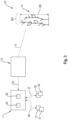
- Fig. 1 is a schematic representation of a combine harvester 1 shown in side view.
- the combine harvester 1 has a cutting unit designed as an attachment 2 for cutting and picking up crop 14.
- the attachment 2 is preferably interchangeable with another attachment 2, so that the harvesting machine 1 can be adapted to harvesting different types of fruit.
- the term crop 14 is understood to mean the entire material picked up from the field by the attachment 2, ie grain and non-grain components.
- a field is mown by the attachment 2 and the picked crop 14 is fed to an inclined conveyor 3.
- the crop 14 picked up by the attachment 2 is fed to a threshing unit 4 for threshing.
- Dem Threshing unit 4 is followed by a separation arrangement 5 in terms of process technology.
- the crop stream fed to the threshing unit 4 is then fed to the separating arrangement 5 - without the grain already obtained here.
- the separation arrangement 5 the crop 14 with the grain remaining in it is moved in such a way that the remaining grain is separated from the straw and the other crop 14 as far as possible.
- the grain obtained in the threshing mechanism 4 and the separation arrangement 5 is then fed to a cleaning arrangement 6.
- the cleaning arrangement 6 which is regularly multi-stage, non-grain components carried in the grain up to this point, e.g. B. chaff and straw parts, as well as unthreshed material, such as ears, tips or awns, are separated from the grain.
- the cleaned grain then arrives by means of a transport arrangement 8, e.g. B.
- the threshed straw - i.e. the remaining crop 14 in the separation arrangement 5 - can be deposited by the combine harvester 1, e.g. B. as a swath along a lane.
- the remaining crop 14 can be spread over the field using a distribution arrangement 7.
- the attachment 2 which is designed as a cutting unit, has a reel 15 which runs transversely to the direction of travel FR of the combine harvester 1 and which already acts on the still uncut crop 14 through the reel tines 16 arranged on it.
- the primary task of the reel 15 is to feed the crop 14 to a knife bar 17 which has a movable knife 18.
- the knife 18 oscillates at a cutting frequency so that the crop 14 is cut and falls onto a cutting table 20, on the front of which the knife bar 17 is located.
- the crop 14 is then conveyed laterally to the inclined conveyor 3 by means of a cross conveyor screw 19, possibly under further influence by the reel 15.
- 26a denotes one of two reel support arms arranged on the outside of the attachment 2, which are also referred to below as outer reel support arms 26a.
- a control unit 11 assigned to the attachment 2 is provided for controlling the attachment 2.
- the control unit 11 is arranged on or in the combine harvester 1.
- the control unit 11 can also be arranged on the attachment 2 or integrated into it.
- the attachment 2 is assigned at least one sensor device 12, which is set up to detect an apron VF, i.e. the area in front of the attachment 2 with crop 14 to be harvested.
- the at least one sensor device 12 can be arranged on the roof of the cabin 21.
- a substantially central arrangement of the sensor device 12 comes into consideration.
- An arrangement of two sensor devices 12 on the roof of the cabin 21 is also conceivable, the arrangement of the two sensor devices 12 being selected such that they have a detection area that overlaps one another in sections.
- the at least one sensor device 12 can be arranged on the attachment 2, which is indicated by the dashed line representation of the sensor device 12.
- a lateral arrangement of the at least one sensor device 12 on the support frame 22 of the attachment 2 can be provided.
- the at least one sensor device 12 sends one or more sensor beams 13 onto the crop 3 located in the front VF of the attachment 2.
- Fig. 2 a perspective view of the attachment 2 is shown schematically.
- the attachment 2 shown is a so-called belt cutting unit or draper.
- the cut and picked-up crop 14 is fed from opposing conveyor belts 23 in the lateral direction - conveying direction 25 - to a centrally arranged feed roller 24.
- the essential parts and components are the same in terms of their functionality, so that the ones already in Fig. 1 reference numerals used are retained.
- the at least one sensor device 12 is arranged on the outside of the attachment 2.
- sensor devices 12 are arranged on both outer sides of the attachment 2.
- the reel 15 is divided into at least two reel segments 15a, 15b.
- the reel segments 15a, 15b are articulated on reel support arms 26a, 26i, only one of which is shown in the view Fig. 2 is visibly displayed.
- the reference number 26i denotes the reel support arm arranged between the two reel segments 15a, 15b, which is also referred to below as the inner reel support arm 26i.
- the two reel segments 15a, 15b are articulated to the inner reel support arm 26i.
- the reel tines 16 are each arranged on tine supports 27, which extend over the width of the respective reel segment 15a, 15b.
- Each reel segment 15a, 15b has several support stars arranged at a distance from one another on a reel shaft 28 29.
- the tine carriers 27 are arranged essentially evenly distributed over the circumference of the support stars 29.
- a drive 30 is assigned to at least one reel shaft 28, which moves the reel segments 15a, 15b in the direction of rotation DR. With only one drive 30, the reel shafts 28 are connected to one another in an articulated manner.
- the reel 15 or the reel segments 15a, 15b are adjustable both in the vertical direction VR and in the horizontal direction HR in order to be able to adapt the position of the reel 15 to different harvesting conditions.
- actuators 31, 32 in particular electrically or hydraulically operable linear actuators, are arranged on the attachment 2, which are controlled by the control unit 11 assigned to the attachment 2.
- An adjustment of the reel 15 in the horizontal direction HR means a longitudinal displacement in the direction of travel FR by controlling the at least one actuator 32 in order to optimally position the individual reel segments 15a, 15b with respect to the cutter bar 17 in the horizontal direction HR.
- An adjustment of the reel 15 or the reel segments 15a, 15b in the vertical direction VR means a change in distance essentially perpendicular to the cutter bar 17 by controlling the at least one actuator 31.
- a pair of actuators 31, 32 are arranged on each reel support arm 26a, 26i, in order to be able to adjust the respective reel support arm 26a, 26i in the vertical direction VR and/or in the horizontal direction HR by a corresponding control by the control unit 11.
- Fig. 3 shows a schematic representation of the structure of the control unit 11 assigned to the attachment 2.
- the at least one sensor device 12 assigned to the attachment 2 is for generating measurement signals 33 for determining a crop height HB and / or a crop density DB of the crop stock 14 located in the front VF of the attachment 2 furnished.
- the control unit 12 is set up to receive and evaluate the measurement signals 33 generated by the at least one sensor device 12 in order to activate the actuators 31, 32 to carry out a mutually independent change in position of the reel support arms 26a, depending on inventory height values and/or inventory density values determined from the measurement signals 33 , 26i to be controlled automatically.
- the control unit 11 has a storage unit 34 for storing data and a computing unit 35 for processing the data stored in the storage unit 34.
- control commands 36, 37 generated by the control unit 11 are transmitted to it.
- the Control commands 36 are based on the inventory height values and the control commands 37 are based on the inventory density values.
- the at least one sensor device 12 assigned to the attachment 2 can be designed as a LIDAR system, as a camera system, as a radar system and/or as an ultrasound system. Combinations of the systems listed above are also conceivable in order to improve the accuracy in determining the crop height HB and the crop density DB in advance VF of the attachment 2.
- Fig. 4 shows a schematic representation of the attachment 2 in a front view.
- the control unit 11 is set up to divide an inventory strip detected by the at least one sensor device 12 in advance VF of the attachment 2 into several detection segments 38, with at least one detection segment 38 being assigned to an individual reel segment 15a, 15b.
- This in Fig. 4 Attachment 2 shown has three reel support arms 26a, 26i.
- One reel support arm 26a is arranged on the outside of the support frame 22 of the attachment 2, and a third reel support arm 26i is arranged centrally between the two reel segments 15a, 15b. Versions with more than three reel support arms 26a, 26i and more than two reel segments 15a, 15b are discussed below using the Fig. 5 to 7 explained.
- the control unit 11 is preferably set up to control the at least one sensor device 12, to detect the stock strip to be detected in advance VF at a predetermined distance from the front edge or the knife bar 17 of the attachment 2. Furthermore, the control unit 11 can be set up to adjust the distance between the front edge and the beginning of the stock strip to be detected, at least depending on the reaction time of the actuators 31, 32, i.e. the period of time that the actuators 31, 32 require, an adjustment of at least one reel support arm 26a, 26i to be carried out. In this way, a proactive adjustment of the position of the reel segments 15a, 15b to changing harvest conditions can be ensured.
- the control unit 11 is further set up to divide the detection segments 38 into individual area sectors 39 in order to determine the inventory height values and/or inventory density values from the respective measurement signals 33 for the stock height HB and / or the stock density DB of each individual area sector 39 to determine.
- the individual surface sectors 39 can preferably be essentially rectangular and have edge lengths in the range from 0.5 m to 2 m.
- the control unit 11 can be set up to carry out a regression method in order to, depending on the result of the regression method carried out, the control commands 36, 37 for controlling the actuators 31, 32 for a height adjustment and/or to generate a horizontal adjustment of the respective reel support arm 26a, 26i.
- a course of a regression curve 40 determined based on measurement signals 33 for the inventory height HB of each individual area sector 39 is shown in the Fig. 4 shown.
- the surface sectors 39 are distributed over a working width AB of the attachment 2.
- a height position 41, 42, 43 of the respective reel support arm 26a, 26i, which can be set independently of one another, is set according to the course of the regression curve 40.
- the height values H to be set for the height adjustment of the reel segments 15a, 15b through the independent control of the reel support arms 26a, 26i can then be seen from the specific regression curve 40 for the respective location coordinates, over the working width AB of the attachment 2, after calculating the geometry data of the reel segments 15a, 15b, such as reel radius, tine length, etc., can be determined.
- the calculation of the height values H to be set of the reel sections 15a, 15b or their support arms 26a, 26i is possible, for example, using the 90% quantile.
- the 90% quantile of the inventory height HB indicates the height at which 90% of the measured inventory height values are below this.
- a similar calculation procedure using regression or 90% quantile is also used to determine the horizontal adjustment of the respective reel support arm 26a, 26i of the reel segments 15a, 15b.
- a horizontal distance to be set from the cutting edge or the front edge of the knife bar 17 is determined. In this case, however, it is not the crop height HB of the crop 14 that is the influencing factor, but rather the crop density DB.
- the cutting edge or front edge of the knife bar 17 is used as a reference value, so that an optimal cutting table length determined in an upstream automation stage is automatically included in the calculation.
- the reel horizontal adjustment of the reel segments 15a, 15b can preferably be adjusted so that a lambda -Shape or triangular shape of the positioning of the reel segments 15a, 15b.
- the outer sides of the reel segments 15a, 15b are relatively closer to the rear wall of the attachment 2 than the center(s) of the reel segments 15a, 15b in order to give the higher crop flows enough space in the middle to create a throw here and associated with it to avoid crop loss and at the same time to ensure trouble-free crop flow on the sides.
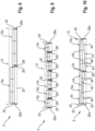
- Fig. 5 shows a schematic and highly simplified representation of the first embodiment of the attachment 2 according to the invention Fig. 4 in top view.
- the in Fig. 5 Reel 15 shown is divided into two reel segments 15a, 15b.
- the two reel support arms 26a are arranged on the outside of the attachment 2 and the third, here the middle, reel support arm 26i is arranged between the adjacent two reel segments 15a, 15b on the attachment 2.
- a horizontal adjustment of the two reel segments 15a, 15b is indicated, which results from a different control of the inner reel support arm 26i compared to the two outer reel support arms 26a.
- the illustration shows an example of a control of the reel support arms 26a, 26i, which results in a funnel shape for positioning the reel segments 15a, 15b.
- the horizontal distance of the outer regions of the reel segments 15a, 15b to the rear wall of the attachment 2 is reduced by controlling the outer reel support arms 26a, while the middle or inner support arm 26i is further extended so that the neighboring ones inner areas of the reel segments 15a, 15b have a smaller distance from the rear wall of the attachment 2 than the outer areas.
- FIG. 6 is a schematic representation of a further development of the attachment 2 according to the invention
- Fig. 5 shown in top view.
- the reel 15 is divided into three reel segments 15a, 15b, 15c.
- the number of independently controlled reel support arms 26a, 26i according to this embodiment increases accordingly to four.
- two inner reel support arms 26i are now provided.
- the inventory strips detected in advance VF of the attachment 2 are divided into at least three detection segments 38. These are in turn divided into individual area sectors 39 in order to determine the crop height values and/or crop density values from the respective measurement signals 33 for the crop height HB and/or the crop density DB of each individual area sector 39, as explained above.
- Fig. 7 shows a schematic representation of a further development of the attachment 2 according to the invention Fig. 6 shown in top view.
- the reel 15 is divided into four reel segments 15a, 15b, 15c, 15d.
- the number of independently controlled reel support arms 26a, 26i according to this embodiment increases accordingly to five.
- the independent control of the reel support arms 26a, 26i or the associated actuators 31, 32 enables, for example, a wave-shaped positioning of the reel segments 15a, 15b, 15c, 15d.
- Fig. 8 a schematic and highly simplified representation of a second embodiment of the attachment 2 according to the invention is shown in a top view.
- the number of adjustable reel support arms 26a, 26i corresponds to twice the number of reel segments 15a, 15b, each reel segment 15a, 15b being arranged between two adjustable reel support arms 26a, 26i.
- each reel segment 15a, 15b has a separate drive 30.
- the actuators 31, 32 of the reel support arms 26a, 26i of each reel segment 15, 15b are here Each pair is independently controlled by the control unit 11 in order to adjust the reel segments 15a, 15b in the vertical direction VR and horizontal direction HR.
- This second embodiment has the advantage that improved adjustment is made possible to adapt to small-scale changes in the crop inventory.
- Fig. 9 shows a schematic representation of a further development of the attachment 2 according to the invention Fig. 8 in top view.
- the reel 15 is divided into seven reel segments 15a, 15b, 15c, ..., 15n, which is only to be understood as an example.
- the number of independently controlled reel support arms 26a, 26i in pairs according to this embodiment increases accordingly to fourteen.
- the finer subdivision of the reel 15 due to the increased number of reel segments 15a, 15b, 15c, ..., 15n enables a further improvement in the adjustment to adapt to small-scale changes in the crop population.
- each reel segment 15a, 15b, 15c, ..., 15n seven drives 30 are provided for this purpose in order to drive each reel segment 15a, 15b, 15c, ..., 15n.
- a schematic and highly simplified representation of a third embodiment of the attachment 2 according to the invention is shown in a top view.
- the reel 15 is divided into two reel segments 15a, 15b, which can be adjusted by three independently controllable reel support arms 26a, 26i, which corresponds to the embodiment already described above Fig. 5 corresponds.
- this embodiment only has one drive 30 to drive the reel 15.
- each reel segment 15a, 15b is divided into at least three sections 44, each section 44 having a variable outer diameter of the arrangement of tine carriers 46 distributed on support stars 45 in the circumferential direction.
- the tine carriers 46 are connected to one another in an articulated manner, as in Fig. 12 shown schematically.
- Each reel segment 15a, 15b has a plurality of support stars 45 arranged at a distance from one another on the reel shaft 28.
- the support stars 45 are designed as a truncated cone in the axial direction in relation to the reel shaft 28, how out Fig. 12 visible.
- the tine supports 46 which extend over the width of the respective section 44 of the reel segment 15a, 15b, are connected to one another by joints 47. This serves to be able to continuously adjust the reel tines on the tine carriers 46 from one side of the attachment 2.
- the tine carriers 46 are guided in an essentially star-shaped manner in the radial direction in guide tracks 48 which are arranged in a substantially star-shaped manner on the truncated cone-shaped support stars 45 and which extend in the axial direction with respect to the reel shaft 28.
- the support stars 34 are arranged axially displaceably on the reel shaft 28, so that an axial displacement 49 of an individual support star 45 leads to a change in the outer diameter of the arrangement of the tine carriers 46. Due to the frustoconical shape of the support stars 45 and the guide tracks 48 running in the axial direction on their circumference, the arms 50 carrying the tine carriers 46 are moved in the radial direction.
Applications Claiming Priority (1)
| Application Number | Priority Date | Filing Date | Title |
|---|---|---|---|
| DE102022107015.8A DE102022107015A1 (de) | 2022-03-24 | 2022-03-24 | Vorsatzgerät, Verfahren zur Steuerung eines Vorsatzgerätes sowie Mähdrescher |
Publications (2)
| Publication Number | Publication Date |
|---|---|
| EP4248730A2 true EP4248730A2 (fr) | 2023-09-27 |
| EP4248730A3 EP4248730A3 (fr) | 2023-12-06 |
Family
ID=85122047
Family Applications (1)
| Application Number | Title | Priority Date | Filing Date |
|---|---|---|---|
| EP23153421.5A Pending EP4248730A3 (fr) | 2022-03-24 | 2023-01-26 | Appareil adaptable, procédé de commande d'un appareil accessoire ainsi que moissonneuse-batteuse |
Country Status (2)
| Country | Link |
|---|---|
| EP (1) | EP4248730A3 (fr) |
| DE (1) | DE102022107015A1 (fr) |
Citations (2)
| Publication number | Priority date | Publication date | Assignee | Title |
|---|---|---|---|---|
| EP1933340B1 (fr) | 2005-09-08 | 2012-08-01 | Sumida Corporation | Dispositif à enroulement, dispositif à enroulement composite et dispositif transformateur |
| EP3841866A1 (fr) | 2019-12-23 | 2021-06-30 | CNH Industrial Belgium N.V. | Systèmes et procédés pour commander une position d'une bobine d'une machine agricole |
Family Cites Families (2)
| Publication number | Priority date | Publication date | Assignee | Title |
|---|---|---|---|---|
| US10757859B2 (en) * | 2017-07-20 | 2020-09-01 | Deere & Company | System for optimizing platform settings based on crop state classification |
| WO2019140512A1 (fr) * | 2018-01-16 | 2019-07-25 | Macdon Industries Ltd. | Commande autonome d'une tête de coupe de moissonneuse |
-
2022
- 2022-03-24 DE DE102022107015.8A patent/DE102022107015A1/de active Pending
-
2023
- 2023-01-26 EP EP23153421.5A patent/EP4248730A3/fr active Pending
Patent Citations (2)
| Publication number | Priority date | Publication date | Assignee | Title |
|---|---|---|---|---|
| EP1933340B1 (fr) | 2005-09-08 | 2012-08-01 | Sumida Corporation | Dispositif à enroulement, dispositif à enroulement composite et dispositif transformateur |
| EP3841866A1 (fr) | 2019-12-23 | 2021-06-30 | CNH Industrial Belgium N.V. | Systèmes et procédés pour commander une position d'une bobine d'une machine agricole |
Also Published As
| Publication number | Publication date |
|---|---|
| DE102022107015A1 (de) | 2023-09-28 |
| EP4248730A3 (fr) | 2023-12-06 |
Similar Documents
| Publication | Publication Date | Title |
|---|---|---|
| EP3494771B1 (fr) | Dispositif de hauteur de coupe automatique | |
| EP3335541B1 (fr) | Procédé de fonctionnement d'une barre de coupe | |
| EP3300580B2 (fr) | Moissonneuse-batteuse pourvue de barre de coupe et dispositif de commande d'une barre de coupe | |
| EP3560314A1 (fr) | Mécanisme de coupe à réglage automatique de l'orientation de dent de rabatteur | |
| DE602004004307T2 (de) | Vorrichtung zur Höheneinstellung eines Spindelmähers | |
| DE102017208442A1 (de) | Selbstlernende, Korrektureingaben berücksichtigende Anordnung zur selbsttätigen Kontrolle eines Arbeitsparameters einer Erntegutförder- und/oder -bearbeitungseinrichtung | |
| EP3000302A1 (fr) | Moissonneuse-batteuse equipee d'un dispositif de distribution | |
| DE102008032191A1 (de) | Selbstfahrende Erntemaschine | |
| DE19528663A1 (de) | Verfahren zur Einstellung einer mobilen Arbeitsmaschine | |
| EP3858129B1 (fr) | Ajustement de la longueur de table de coupe | |
| EP3598886B1 (fr) | Engin d'abattage-façonnage automoteur | |
| EP3527059A1 (fr) | Moissonneuse-batteuse ainsi que son procédé de fonctionnement | |
| EP2769613A1 (fr) | Dispositif de commande pour le fonctionnement d'une moissonneuse et moissonneuse dotée d'un tel dispositif de commande | |
| DE2555283A1 (de) | Anordnung zur automatischen seitenfuehrung von landwirtschaftlich genutzten fahrzeugen | |
| EP4136956A1 (fr) | Procédé de fonctionnement d'une machine de récolte automotrice et machine de récolte automotrice | |
| EP3552473B1 (fr) | Moissonneuse-batteuse avec contrôleur de rouleaux d'amenée | |
| EP4248730A2 (fr) | Appareil adaptable, procédé de commande d'un appareil accessoire ainsi que moissonneuse-batteuse | |
| EP3613273A1 (fr) | Moissonneuse-batteuse | |
| EP4056021A2 (fr) | Barre de coupe | |
| EP3628142B1 (fr) | Dispositif de coupe pour un engin d'abattage-façonnage agricole ainsi que procédé de fonctionnement d'un dispositif de coupe | |
| EP4252519A1 (fr) | Moissonneuse agricole et procédé de commande d'une moissonneuse agricole | |
| EP3400778B1 (fr) | Procédé de fonctionnement d'une moissonneuse autonome | |
| EP4154697A1 (fr) | Système d'aide à la conduite d'un engin d'abattage-façonnage pourvu de mécanisme de coupe de bande | |
| EP4154700A1 (fr) | Engin d'abattage-façonnage pourvu de mécanisme de coupe de bande | |
| EP4129036A1 (fr) | Machine agricole pourvue de composant surveillé par caméra |
Legal Events
| Date | Code | Title | Description |
|---|---|---|---|
| PUAI | Public reference made under article 153(3) epc to a published international application that has entered the european phase |
Free format text: ORIGINAL CODE: 0009012 |
|
| STAA | Information on the status of an ep patent application or granted ep patent |
Free format text: STATUS: THE APPLICATION HAS BEEN PUBLISHED |
|
| AK | Designated contracting states |
Kind code of ref document: A2 Designated state(s): AL AT BE BG CH CY CZ DE DK EE ES FI FR GB GR HR HU IE IS IT LI LT LU LV MC ME MK MT NL NO PL PT RO RS SE SI SK SM TR |
|
| P01 | Opt-out of the competence of the unified patent court (upc) registered |
Effective date: 20230927 |
|
| PUAL | Search report despatched |
Free format text: ORIGINAL CODE: 0009013 |
|
| AK | Designated contracting states |
Kind code of ref document: A3 Designated state(s): AL AT BE BG CH CY CZ DE DK EE ES FI FR GB GR HR HU IE IS IT LI LT LU LV MC ME MK MT NL NO PL PT RO RS SE SI SK SM TR |
|
| RIC1 | Information provided on ipc code assigned before grant |
Ipc: A01D 57/04 20060101AFI20231030BHEP |