EP4248730A2 - Header device, method for controlling a header device, and combine - Google Patents
Header device, method for controlling a header device, and combine Download PDFInfo
- Publication number
- EP4248730A2 EP4248730A2 EP23153421.5A EP23153421A EP4248730A2 EP 4248730 A2 EP4248730 A2 EP 4248730A2 EP 23153421 A EP23153421 A EP 23153421A EP 4248730 A2 EP4248730 A2 EP 4248730A2
- Authority
- EP
- European Patent Office
- Prior art keywords
- reel
- attachment
- segments
- crop
- control unit
- Prior art date
- Legal status (The legal status is an assumption and is not a legal conclusion. Google has not performed a legal analysis and makes no representation as to the accuracy of the status listed.)
- Pending
Links
- 238000000034 method Methods 0.000 title claims description 18
- 238000005259 measurement Methods 0.000 claims abstract description 28
- 230000008859 change Effects 0.000 claims abstract description 13
- 238000001514 detection method Methods 0.000 claims description 24
- 239000000969 carrier Substances 0.000 claims description 15
- 238000004458 analytical method Methods 0.000 claims description 3
- 230000035484 reaction time Effects 0.000 claims description 3
- 238000002604 ultrasonography Methods 0.000 claims description 3
- 238000012417 linear regression Methods 0.000 claims 1
- 238000005520 cutting process Methods 0.000 description 19
- 238000003306 harvesting Methods 0.000 description 12
- 238000011161 development Methods 0.000 description 11
- 230000018109 developmental process Effects 0.000 description 11
- 210000005069 ears Anatomy 0.000 description 6
- 238000000926 separation method Methods 0.000 description 5
- 238000003860 storage Methods 0.000 description 5
- 230000006978 adaptation Effects 0.000 description 4
- 238000004364 calculation method Methods 0.000 description 4
- 239000000463 material Substances 0.000 description 4
- 230000008901 benefit Effects 0.000 description 3
- 238000004140 cleaning Methods 0.000 description 3
- 238000006073 displacement reaction Methods 0.000 description 3
- 238000009826 distribution Methods 0.000 description 3
- 239000010902 straw Substances 0.000 description 3
- 230000006872 improvement Effects 0.000 description 2
- 230000007246 mechanism Effects 0.000 description 2
- 238000012545 processing Methods 0.000 description 2
- 238000000611 regression analysis Methods 0.000 description 2
- 238000012935 Averaging Methods 0.000 description 1
- 244000188595 Brassica sinapistrum Species 0.000 description 1
- 235000004977 Brassica sinapistrum Nutrition 0.000 description 1
- 241000196324 Embryophyta Species 0.000 description 1
- 230000001419 dependent effect Effects 0.000 description 1
- 238000013461 design Methods 0.000 description 1
- 238000011982 device technology Methods 0.000 description 1
- 235000013399 edible fruits Nutrition 0.000 description 1
- 230000000694 effects Effects 0.000 description 1
- 238000005516 engineering process Methods 0.000 description 1
- 230000007613 environmental effect Effects 0.000 description 1
- 238000011156 evaluation Methods 0.000 description 1
- 238000010327 methods by industry Methods 0.000 description 1
- 210000000056 organ Anatomy 0.000 description 1
- 230000008569 process Effects 0.000 description 1
- 230000008439 repair process Effects 0.000 description 1
- 230000000717 retained effect Effects 0.000 description 1
- 239000002689 soil Substances 0.000 description 1
- 238000012549 training Methods 0.000 description 1
- 238000011144 upstream manufacturing Methods 0.000 description 1
Images


Classifications
-
- A—HUMAN NECESSITIES
- A01—AGRICULTURE; FORESTRY; ANIMAL HUSBANDRY; HUNTING; TRAPPING; FISHING
- A01D—HARVESTING; MOWING
- A01D57/00—Delivering mechanisms for harvesters or mowers
- A01D57/01—Devices for leading crops to the mowing apparatus
- A01D57/02—Devices for leading crops to the mowing apparatus using reels
- A01D57/04—Arrangements for changing the position of the reels
-
- A—HUMAN NECESSITIES
- A01—AGRICULTURE; FORESTRY; ANIMAL HUSBANDRY; HUNTING; TRAPPING; FISHING
- A01D—HARVESTING; MOWING
- A01D41/00—Combines, i.e. harvesters or mowers combined with threshing devices
- A01D41/12—Details of combines
- A01D41/14—Mowing tables
- A01D41/141—Automatic header control
Definitions
- the present invention relates to an attachment according to the preamble of claim 1. Furthermore, the present invention relates to a method for controlling an attachment according to the preamble of claim 16 and a combine harvester according to claim 18.
- the attachment in question is any attachment that is set up to cut and pick up crops.
- Such an attachment includes a reel which extends essentially over the entire width of the attachment.
- the reel has at least two reel segments, which are arranged on reel support arms.
- the reel segments can be adjusted in the vertical and horizontal directions by actuators arranged on the attachment.
- a control unit is assigned to the attachment to control the actuators.
- the reel segments are adjusted synchronously in the vertical and horizontal directions. This is achieved using hydraulic master/slave cylinders as actuators.
- An operator only adjusts the height and the horizontal distance to the cutter bar of the attachment so that the crop, such as grain, reaches the attachment evenly with a continuous crop flow. If the reel is set too high so that the reel tines no longer touch the crop, especially the ears, the crop can become jammed due to a lack of guidance in the attachment. This results in an uneven crop flow with sometimes high load peaks, which results in high crop losses and greater wear and tear on the working organs and drives of a combine harvester that carries the attachment.
- the situation is similar if the horizontal adjustment of the reel is not optimal. If the horizontal distance of the reel is chosen too far in front of the knife bar, the crop cannot be guided sufficiently and an uneven crop flow occurs in the cutting trough of an attachment designed as a screw cutter or on the conveyor belts of an attachment designed as a belt cutter, with the well-known consequences. If the horizontal distance between the reel and the knife bar is too short, the harvested crop can be compressed in front of the conveyor elements. This can, especially in the case of rapeseed, lead to the harvested material being carried away by the reel, with the well-known consequences.
- the belt cutting unit has a central section and two side sections, each of which can be deflected in the vertical direction about a horizontal axis relative to the central section in order to be able to follow a change in the ground contour.
- a reel of the belt cutting unit is divided into two reel segments, which are supported by two outer, synchronously moved reel support arms and an inner reel support arm. The two reel segments are articulated at their mutually facing ends on the inner reel support arm.
- the inner reel support arm is movable independently of the two outer reel support arms.
- the belt cutting unit has a central section and two side sections, each of which can be deflected in the vertical direction about a horizontal axis relative to the central section in order to be able to follow a change in the ground contour.
- a reel of the belt cutting unit is divided into three reel segments, which are supported by two outer reel support arms and two inner reel support arms. The two outer reel segments are articulated at their mutually facing ends on the inner reel support arms. According to the EP 3 841 866 A1 It is intended that the reel segments can be adjusted independently of one another.
- the invention is based on the object of developing an attachment and a method for controlling the attachment, which is characterized by an improved adaptation of the reel setting to small-scale changes in the crop population.
- an attachment with a reel is proposed, the reel having at least two reel segments which are articulated on reel support arms, with actuators being arranged on the attachment which are set up to adjust the reel segments in the vertical and horizontal directions, whereby A control unit is assigned to the attachment for controlling the actuators. Swivel joints are provided to connect the reel segments to the reel support arms.
- At least one sensor device is assigned to the attachment, which is set up to generate measurement signals for determining a crop height and/or a crop density of a crop stock located in advance of the attachment, the control unit being set up to receive and evaluate the measurement signals in order to automatically control the actuators to carry out an independent change in position of the reel support arms depending on the inventory height values and/or inventory density values determined from the measurement signals.
- the proposed solution is based, first of all, on the fundamental knowledge that individual adjustment of the horizontal position and vertical position of the reel segments is a necessary prerequisite for avoiding grain losses that occur on the attachment itself. Detecting the crop height and/or the crop density of the crop inventory located in front of the attachment has the advantage that small-scale changes can be responded to better and more efficiently in order to achieve an optimized setting of the individual reel segments through the independent adjustment of the reel support arms. This allows the resulting crop loss to be reduced. In addition, through the optimized setting of the individual reel segments, a higher throughput can be achieved with constant or lower crop losses. In addition, an improvement in the crop flow in the header can be achieved, especially in difficult harvest situations, especially when stored grain occurs.
- the automatic control of the respective actuators to carry out an independent change in the position of the reel support arms in the horizontal and/or vertical direction relieves the operator of the necessary adjustment tasks, especially in difficult harvesting situations.
- the at least one sensor device provides the measurement signals as input variables for the analytical determination of inventory height values and/or inventory density values by the control unit.
- the at least one sensor device being a LIDAR system, a camera system, as Radar system and / or can be designed as an ultrasound system. It can be provided to combine differently designed sensor devices with one another in order to improve the accuracy of the determination of the inventory height values and/or the inventory density values, which also improves the control of the respective actuators.
- the control unit can preferably be set up to divide an inventory strip detected by the at least one sensor device in advance of the attachment into several detection segments, with at least one detection segment being assigned to an individual reel segment.
- the multiple detection segments cover at least the working width of the attachment.
- a further detection segment can be assigned to an area to the side of the attachment. The assignment of an additional detection segment on both sides to the side of the attachment can be provided if the presence of a crop edge is also to be detected by the at least one sensor device, which serves as an orientation aid for guiding the attachment or the combine harvester carrying the attachment.
- control unit can be set up to divide the detection segments into individual area sectors in order to determine the crop height values and/or crop density values from the respective measurement signals for the crop height and/or the crop density of each individual area sector.
- the division of the detection segments into individual area sectors results in a higher resolution when determining the crop height values and/or the crop density values, which means that the individual reel segments can be controlled more precisely and are better adapted to small-scale changes in the crop inventory.
- control unit can be set up to control the sensor device to detect the stock strip to be detected in advance at a predetermined distance from the front edge or knife bar of the attachment, the control unit being set up to determine the distance between the front edge and the beginning of the strip to be detected To determine the inventory strip at least depending on the reaction time of the actuators. This ensures that there is sufficient lead time for the evaluation and generation of control commands by the control unit in order to automatically control the actuators for independently changing the position of the reel support arms.
- the individual surface sectors can preferably be essentially rectangular and have edge lengths in the range from 0.5 m to 2 m.
- the size of the surface sectors in the direction of movement of the attachment and transversely should be chosen so that there is an optimum between a representative measurement and a suitable height movement and/or horizontal movement of the reel.
- the height adjustment and the horizontal adjustment of the individual reel segments can be calculated in order to be able to automatically control an independent change in position of the reel support arms that is optimally adapted to the existing harvest conditions.
- control unit can be set up to carry out a regression analysis in order to generate control commands for controlling the actuators for a height adjustment and/or a horizontal adjustment of the respective reel support arm depending on the analysis result.
- the calculation can be carried out using regression analysis of the crop height values and/or the crop density values in the individual area sectors across the width of the attachment.
- the height adjustment and/or the horizontal adjustment of the reel segments through the independent control of the reel support arms can then be determined from a specific regression curve for the respective location coordinates, viewed over the working width of the attachment, after calculating the geometric data of the reel segments, such as reel radius, tine length, etc become.
- control unit can be set up to use linear or nonlinear regression, in particular quantile regression, as a regression method.
- linear or nonlinear regression in particular quantile regression
- other analysis methods are also conceivable, such as averaging or iterative approximation methods.
- the number of adjustable reel support arms can correspond to the number of reel segments increased by the value 1, with two reel support arms on the outside of the attachment and the third or each other Reel support arm is arranged between the adjacent reel segments on the attachment.
- the attachment can only have one drive for generating a rotational movement of all reel segments, which are connected to one another by a common reel shaft.
- the number of adjustable reel support arms can correspond to twice the number of reel segments, with each reel segment being arranged between two adjustable reel support arms.
- Each reel segment can have a separate drive to generate a rotational movement of the respective reel segment.
- the reel support arms of the respective reel segment can only be adjustable in pairs. According to this development, a high degree of functional fulfillment can be achieved with a design of the reel which has two reel segments and four reel support arms that can be adjusted independently in pairs. With an increasing, especially odd, number of reel segments, a further increase in the degree of functional fulfillment can be achieved, since with the increasing number of reel segments the flexibility increases in order to be able to react to small-scale changes in the crop inventory, i.e. in particular with regard to crop density and / or crop height.
- each reel segment can be divided into at least three sections, each section having a variable outer diameter of the arrangement of tine carriers distributed on support stars in the circumferential direction. Adjusting the outer diameter of the respective reel segment or the tine carrier with tines arranged thereon in sections enables more flexible adaptation to changing harvest conditions, especially in the acceptance area of an individual reel segment.
- each reel segment can have a plurality of support stars which are arranged on a reel shaft at a distance from one another and are truncated cone-shaped in the axial direction, as well as tine carriers which extend over the width of the respective section of the reel segment and are connected to one another by joints, the tine carriers being on the truncated cone-shaped support stars in a substantially star shape arranged
- Guideways are guided in an adjustable radial direction in relation to the reel shaft.
- the star-shaped guide tracks on the respective support star run axially parallel to the reel shaft.
- a method for controlling an attachment with a reel is proposed, the reel having at least two reel segments which are articulated on reel support arms, the reel segments being adjusted in the vertical and horizontal directions by actuators arranged on the attachment, the Actuators are controlled by a control unit assigned to the attachment, with the attachment being assigned at least one sensor device, through which measurement signals for determining a crop height and / or a crop density of a crop stock located in advance of the attachment are generated, the measurement signals being received and evaluated by the control unit in order to automatically control the actuators to carry out an independent change in position of the reel support arms depending on the inventory height values and/or inventory density values determined from the measurement signals.
- an existing strip of the apron of the attachment which runs parallel to the working width of the attachment and is detected by the at least one sensor device, is divided into several detection segments, with at least two detection segments being assigned to a single reel segment and one detection segment to an area to the side of the attachment is assigned, the recording segments being subdivided into individual area sectors in order to determine the stock height values and/or stock density values from the respective measurement signals for the stock height and/or the stock density of each individual area sector.
- the size of the area sectors can be specified automatically, for example depending on the working width of the attachment, or by manual input by an operator.
- the method for controlling the attachment can have all the features described in connection with the attachment according to the invention according to claims 2 to 15 individually or in combination.
- a combine harvester with an attachment, the attachment comprising a reel, the reel having at least two reel segments which are arranged on reel support arms, the reel segments being actuated by actuators arranged on the attachment can be adjusted vertically and horizontally, with the attachment for controlling the actuators being assigned a control unit, characterized in that the attachment is designed according to one of the preceding claims 1 to 15 and the control unit is set up to carry out a method according to one of claims 16 or 17 .
- a significant effect is a higher throughput of the combine harvester with constant or lower grain losses.
- a higher quality of the processed crop can be achieved by a more even and continuous feed of the crop into the combine. This also leads to a better and more even distribution of chopped material and thus to less effort in tilling the soil and to better starting conditions for the following crop.
- Another advantage is a lower mechanical load on the work units processing the crop and thus a longer service life and fewer repairs.
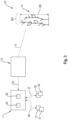
- Fig. 1 is a schematic representation of a combine harvester 1 shown in side view.
- the combine harvester 1 has a cutting unit designed as an attachment 2 for cutting and picking up crop 14.
- the attachment 2 is preferably interchangeable with another attachment 2, so that the harvesting machine 1 can be adapted to harvesting different types of fruit.
- the term crop 14 is understood to mean the entire material picked up from the field by the attachment 2, ie grain and non-grain components.
- a field is mown by the attachment 2 and the picked crop 14 is fed to an inclined conveyor 3.
- the crop 14 picked up by the attachment 2 is fed to a threshing unit 4 for threshing.
- Dem Threshing unit 4 is followed by a separation arrangement 5 in terms of process technology.
- the crop stream fed to the threshing unit 4 is then fed to the separating arrangement 5 - without the grain already obtained here.
- the separation arrangement 5 the crop 14 with the grain remaining in it is moved in such a way that the remaining grain is separated from the straw and the other crop 14 as far as possible.
- the grain obtained in the threshing mechanism 4 and the separation arrangement 5 is then fed to a cleaning arrangement 6.
- the cleaning arrangement 6 which is regularly multi-stage, non-grain components carried in the grain up to this point, e.g. B. chaff and straw parts, as well as unthreshed material, such as ears, tips or awns, are separated from the grain.
- the cleaned grain then arrives by means of a transport arrangement 8, e.g. B.
- the threshed straw - i.e. the remaining crop 14 in the separation arrangement 5 - can be deposited by the combine harvester 1, e.g. B. as a swath along a lane.
- the remaining crop 14 can be spread over the field using a distribution arrangement 7.
- the attachment 2 which is designed as a cutting unit, has a reel 15 which runs transversely to the direction of travel FR of the combine harvester 1 and which already acts on the still uncut crop 14 through the reel tines 16 arranged on it.
- the primary task of the reel 15 is to feed the crop 14 to a knife bar 17 which has a movable knife 18.
- the knife 18 oscillates at a cutting frequency so that the crop 14 is cut and falls onto a cutting table 20, on the front of which the knife bar 17 is located.
- the crop 14 is then conveyed laterally to the inclined conveyor 3 by means of a cross conveyor screw 19, possibly under further influence by the reel 15.
- 26a denotes one of two reel support arms arranged on the outside of the attachment 2, which are also referred to below as outer reel support arms 26a.
- a control unit 11 assigned to the attachment 2 is provided for controlling the attachment 2.
- the control unit 11 is arranged on or in the combine harvester 1.
- the control unit 11 can also be arranged on the attachment 2 or integrated into it.
- the attachment 2 is assigned at least one sensor device 12, which is set up to detect an apron VF, i.e. the area in front of the attachment 2 with crop 14 to be harvested.
- the at least one sensor device 12 can be arranged on the roof of the cabin 21.
- a substantially central arrangement of the sensor device 12 comes into consideration.
- An arrangement of two sensor devices 12 on the roof of the cabin 21 is also conceivable, the arrangement of the two sensor devices 12 being selected such that they have a detection area that overlaps one another in sections.
- the at least one sensor device 12 can be arranged on the attachment 2, which is indicated by the dashed line representation of the sensor device 12.
- a lateral arrangement of the at least one sensor device 12 on the support frame 22 of the attachment 2 can be provided.
- the at least one sensor device 12 sends one or more sensor beams 13 onto the crop 3 located in the front VF of the attachment 2.
- Fig. 2 a perspective view of the attachment 2 is shown schematically.
- the attachment 2 shown is a so-called belt cutting unit or draper.
- the cut and picked-up crop 14 is fed from opposing conveyor belts 23 in the lateral direction - conveying direction 25 - to a centrally arranged feed roller 24.
- the essential parts and components are the same in terms of their functionality, so that the ones already in Fig. 1 reference numerals used are retained.
- the at least one sensor device 12 is arranged on the outside of the attachment 2.
- sensor devices 12 are arranged on both outer sides of the attachment 2.
- the reel 15 is divided into at least two reel segments 15a, 15b.
- the reel segments 15a, 15b are articulated on reel support arms 26a, 26i, only one of which is shown in the view Fig. 2 is visibly displayed.
- the reference number 26i denotes the reel support arm arranged between the two reel segments 15a, 15b, which is also referred to below as the inner reel support arm 26i.
- the two reel segments 15a, 15b are articulated to the inner reel support arm 26i.
- the reel tines 16 are each arranged on tine supports 27, which extend over the width of the respective reel segment 15a, 15b.
- Each reel segment 15a, 15b has several support stars arranged at a distance from one another on a reel shaft 28 29.
- the tine carriers 27 are arranged essentially evenly distributed over the circumference of the support stars 29.
- a drive 30 is assigned to at least one reel shaft 28, which moves the reel segments 15a, 15b in the direction of rotation DR. With only one drive 30, the reel shafts 28 are connected to one another in an articulated manner.
- the reel 15 or the reel segments 15a, 15b are adjustable both in the vertical direction VR and in the horizontal direction HR in order to be able to adapt the position of the reel 15 to different harvesting conditions.
- actuators 31, 32 in particular electrically or hydraulically operable linear actuators, are arranged on the attachment 2, which are controlled by the control unit 11 assigned to the attachment 2.
- An adjustment of the reel 15 in the horizontal direction HR means a longitudinal displacement in the direction of travel FR by controlling the at least one actuator 32 in order to optimally position the individual reel segments 15a, 15b with respect to the cutter bar 17 in the horizontal direction HR.
- An adjustment of the reel 15 or the reel segments 15a, 15b in the vertical direction VR means a change in distance essentially perpendicular to the cutter bar 17 by controlling the at least one actuator 31.
- a pair of actuators 31, 32 are arranged on each reel support arm 26a, 26i, in order to be able to adjust the respective reel support arm 26a, 26i in the vertical direction VR and/or in the horizontal direction HR by a corresponding control by the control unit 11.
- Fig. 3 shows a schematic representation of the structure of the control unit 11 assigned to the attachment 2.
- the at least one sensor device 12 assigned to the attachment 2 is for generating measurement signals 33 for determining a crop height HB and / or a crop density DB of the crop stock 14 located in the front VF of the attachment 2 furnished.
- the control unit 12 is set up to receive and evaluate the measurement signals 33 generated by the at least one sensor device 12 in order to activate the actuators 31, 32 to carry out a mutually independent change in position of the reel support arms 26a, depending on inventory height values and/or inventory density values determined from the measurement signals 33 , 26i to be controlled automatically.
- the control unit 11 has a storage unit 34 for storing data and a computing unit 35 for processing the data stored in the storage unit 34.
- control commands 36, 37 generated by the control unit 11 are transmitted to it.
- the Control commands 36 are based on the inventory height values and the control commands 37 are based on the inventory density values.
- the at least one sensor device 12 assigned to the attachment 2 can be designed as a LIDAR system, as a camera system, as a radar system and/or as an ultrasound system. Combinations of the systems listed above are also conceivable in order to improve the accuracy in determining the crop height HB and the crop density DB in advance VF of the attachment 2.
- Fig. 4 shows a schematic representation of the attachment 2 in a front view.
- the control unit 11 is set up to divide an inventory strip detected by the at least one sensor device 12 in advance VF of the attachment 2 into several detection segments 38, with at least one detection segment 38 being assigned to an individual reel segment 15a, 15b.
- This in Fig. 4 Attachment 2 shown has three reel support arms 26a, 26i.
- One reel support arm 26a is arranged on the outside of the support frame 22 of the attachment 2, and a third reel support arm 26i is arranged centrally between the two reel segments 15a, 15b. Versions with more than three reel support arms 26a, 26i and more than two reel segments 15a, 15b are discussed below using the Fig. 5 to 7 explained.
- the control unit 11 is preferably set up to control the at least one sensor device 12, to detect the stock strip to be detected in advance VF at a predetermined distance from the front edge or the knife bar 17 of the attachment 2. Furthermore, the control unit 11 can be set up to adjust the distance between the front edge and the beginning of the stock strip to be detected, at least depending on the reaction time of the actuators 31, 32, i.e. the period of time that the actuators 31, 32 require, an adjustment of at least one reel support arm 26a, 26i to be carried out. In this way, a proactive adjustment of the position of the reel segments 15a, 15b to changing harvest conditions can be ensured.
- the control unit 11 is further set up to divide the detection segments 38 into individual area sectors 39 in order to determine the inventory height values and/or inventory density values from the respective measurement signals 33 for the stock height HB and / or the stock density DB of each individual area sector 39 to determine.
- the individual surface sectors 39 can preferably be essentially rectangular and have edge lengths in the range from 0.5 m to 2 m.
- the control unit 11 can be set up to carry out a regression method in order to, depending on the result of the regression method carried out, the control commands 36, 37 for controlling the actuators 31, 32 for a height adjustment and/or to generate a horizontal adjustment of the respective reel support arm 26a, 26i.
- a course of a regression curve 40 determined based on measurement signals 33 for the inventory height HB of each individual area sector 39 is shown in the Fig. 4 shown.
- the surface sectors 39 are distributed over a working width AB of the attachment 2.
- a height position 41, 42, 43 of the respective reel support arm 26a, 26i, which can be set independently of one another, is set according to the course of the regression curve 40.
- the height values H to be set for the height adjustment of the reel segments 15a, 15b through the independent control of the reel support arms 26a, 26i can then be seen from the specific regression curve 40 for the respective location coordinates, over the working width AB of the attachment 2, after calculating the geometry data of the reel segments 15a, 15b, such as reel radius, tine length, etc., can be determined.
- the calculation of the height values H to be set of the reel sections 15a, 15b or their support arms 26a, 26i is possible, for example, using the 90% quantile.
- the 90% quantile of the inventory height HB indicates the height at which 90% of the measured inventory height values are below this.
- a similar calculation procedure using regression or 90% quantile is also used to determine the horizontal adjustment of the respective reel support arm 26a, 26i of the reel segments 15a, 15b.
- a horizontal distance to be set from the cutting edge or the front edge of the knife bar 17 is determined. In this case, however, it is not the crop height HB of the crop 14 that is the influencing factor, but rather the crop density DB.
- the cutting edge or front edge of the knife bar 17 is used as a reference value, so that an optimal cutting table length determined in an upstream automation stage is automatically included in the calculation.
- the reel horizontal adjustment of the reel segments 15a, 15b can preferably be adjusted so that a lambda -Shape or triangular shape of the positioning of the reel segments 15a, 15b.
- the outer sides of the reel segments 15a, 15b are relatively closer to the rear wall of the attachment 2 than the center(s) of the reel segments 15a, 15b in order to give the higher crop flows enough space in the middle to create a throw here and associated with it to avoid crop loss and at the same time to ensure trouble-free crop flow on the sides.
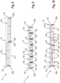
- Fig. 5 shows a schematic and highly simplified representation of the first embodiment of the attachment 2 according to the invention Fig. 4 in top view.
- the in Fig. 5 Reel 15 shown is divided into two reel segments 15a, 15b.
- the two reel support arms 26a are arranged on the outside of the attachment 2 and the third, here the middle, reel support arm 26i is arranged between the adjacent two reel segments 15a, 15b on the attachment 2.
- a horizontal adjustment of the two reel segments 15a, 15b is indicated, which results from a different control of the inner reel support arm 26i compared to the two outer reel support arms 26a.
- the illustration shows an example of a control of the reel support arms 26a, 26i, which results in a funnel shape for positioning the reel segments 15a, 15b.
- the horizontal distance of the outer regions of the reel segments 15a, 15b to the rear wall of the attachment 2 is reduced by controlling the outer reel support arms 26a, while the middle or inner support arm 26i is further extended so that the neighboring ones inner areas of the reel segments 15a, 15b have a smaller distance from the rear wall of the attachment 2 than the outer areas.
- FIG. 6 is a schematic representation of a further development of the attachment 2 according to the invention
- Fig. 5 shown in top view.
- the reel 15 is divided into three reel segments 15a, 15b, 15c.
- the number of independently controlled reel support arms 26a, 26i according to this embodiment increases accordingly to four.
- two inner reel support arms 26i are now provided.
- the inventory strips detected in advance VF of the attachment 2 are divided into at least three detection segments 38. These are in turn divided into individual area sectors 39 in order to determine the crop height values and/or crop density values from the respective measurement signals 33 for the crop height HB and/or the crop density DB of each individual area sector 39, as explained above.
- Fig. 7 shows a schematic representation of a further development of the attachment 2 according to the invention Fig. 6 shown in top view.
- the reel 15 is divided into four reel segments 15a, 15b, 15c, 15d.
- the number of independently controlled reel support arms 26a, 26i according to this embodiment increases accordingly to five.
- the independent control of the reel support arms 26a, 26i or the associated actuators 31, 32 enables, for example, a wave-shaped positioning of the reel segments 15a, 15b, 15c, 15d.
- Fig. 8 a schematic and highly simplified representation of a second embodiment of the attachment 2 according to the invention is shown in a top view.
- the number of adjustable reel support arms 26a, 26i corresponds to twice the number of reel segments 15a, 15b, each reel segment 15a, 15b being arranged between two adjustable reel support arms 26a, 26i.
- each reel segment 15a, 15b has a separate drive 30.
- the actuators 31, 32 of the reel support arms 26a, 26i of each reel segment 15, 15b are here Each pair is independently controlled by the control unit 11 in order to adjust the reel segments 15a, 15b in the vertical direction VR and horizontal direction HR.
- This second embodiment has the advantage that improved adjustment is made possible to adapt to small-scale changes in the crop inventory.
- Fig. 9 shows a schematic representation of a further development of the attachment 2 according to the invention Fig. 8 in top view.
- the reel 15 is divided into seven reel segments 15a, 15b, 15c, ..., 15n, which is only to be understood as an example.
- the number of independently controlled reel support arms 26a, 26i in pairs according to this embodiment increases accordingly to fourteen.
- the finer subdivision of the reel 15 due to the increased number of reel segments 15a, 15b, 15c, ..., 15n enables a further improvement in the adjustment to adapt to small-scale changes in the crop population.
- each reel segment 15a, 15b, 15c, ..., 15n seven drives 30 are provided for this purpose in order to drive each reel segment 15a, 15b, 15c, ..., 15n.
- a schematic and highly simplified representation of a third embodiment of the attachment 2 according to the invention is shown in a top view.
- the reel 15 is divided into two reel segments 15a, 15b, which can be adjusted by three independently controllable reel support arms 26a, 26i, which corresponds to the embodiment already described above Fig. 5 corresponds.
- this embodiment only has one drive 30 to drive the reel 15.
- each reel segment 15a, 15b is divided into at least three sections 44, each section 44 having a variable outer diameter of the arrangement of tine carriers 46 distributed on support stars 45 in the circumferential direction.
- the tine carriers 46 are connected to one another in an articulated manner, as in Fig. 12 shown schematically.
- Each reel segment 15a, 15b has a plurality of support stars 45 arranged at a distance from one another on the reel shaft 28.
- the support stars 45 are designed as a truncated cone in the axial direction in relation to the reel shaft 28, how out Fig. 12 visible.
- the tine supports 46 which extend over the width of the respective section 44 of the reel segment 15a, 15b, are connected to one another by joints 47. This serves to be able to continuously adjust the reel tines on the tine carriers 46 from one side of the attachment 2.
- the tine carriers 46 are guided in an essentially star-shaped manner in the radial direction in guide tracks 48 which are arranged in a substantially star-shaped manner on the truncated cone-shaped support stars 45 and which extend in the axial direction with respect to the reel shaft 28.
- the support stars 34 are arranged axially displaceably on the reel shaft 28, so that an axial displacement 49 of an individual support star 45 leads to a change in the outer diameter of the arrangement of the tine carriers 46. Due to the frustoconical shape of the support stars 45 and the guide tracks 48 running in the axial direction on their circumference, the arms 50 carrying the tine carriers 46 are moved in the radial direction.
Abstract
Die vorliegende Erfindung betrifft ein Vorsatzgerät (2) mit einer Haspel (15), wobei die Haspel (15) zumindest zwei Haspelsegmente (15a, 15b, ..., 15n) aufweist, welche an Haspeltragarmen (26a, 26i) angelenkt sind, wobei an dem Vorsatzgerät (2) Aktoren (31, 32) angeordnet sind, welche dazu eingerichtet sind, die Haspelsegmente (15a, 15b, ..., 15n) in vertikaler und horizontaler Richtung (VR, HR) zu verstellen, wobei dem Vorsatzgerät (2) zur Ansteuerung der Aktoren (31, 32) eine Steuereinheit (11) zugeordnet ist, wobei dem Vorsatzgerät (2) zumindest eine Sensoreinrichtung (12) zugeordnet ist, die zur Generierung von Messsignalen (33) zur Bestimmung einer Bestandshöhe (HB) und/oder einer Bestandsdichte (BD) eines im Vorfeld (VF) des Vorsatzgerätes (2) befindlichen Erntegutbestands (14) eingerichtet ist, wobei die Steuereinheit (11) dazu eingerichtet ist, die Messsignale (33) zu empfangen und auszuwerten, um in Abhängigkeit von aus den Messsignalen (33) bestimmten Bestandshöhenwerten und/oder Bestandsdichtewerten die Aktoren (31, 32) zur Ausführung einer voneinander unabhängigen Positionsänderung der Haspeltragarme (26a, 26i) automatisch anzusteuern.The present invention relates to an attachment (2) with a reel (15), the reel (15) having at least two reel segments (15a, 15b, ..., 15n), which are articulated to reel support arms (26a, 26i), wherein Actuators (31, 32) are arranged on the attachment (2), which are designed to adjust the reel segments (15a, 15b, ..., 15n) in the vertical and horizontal directions (VR, HR), the attachment ( 2) a control unit (11) is assigned to control the actuators (31, 32), wherein the attachment (2) is assigned at least one sensor device (12) which is used to generate measurement signals (33) to determine an inventory height (HB) and / or a stock density (BD) of a crop stock (14) located in advance (VF) of the attachment (2), the control unit (11) being set up to receive and evaluate the measurement signals (33) in order to depend on to automatically control the actuators (31, 32) from the inventory height values and/or inventory density values determined from the measurement signals (33) in order to carry out a mutually independent change in position of the reel support arms (26a, 26i).
Description
Die vorliegende Erfindung betrifft ein Vorsatzgerät gemäß dem Oberbegriff des Anspruches 1. Weiterhin hat die vorliegende Erfindung ein Verfahren zur Steuerung eines Vorsatzgerätes gemäß dem Oberbegriff des Anspruches 16 sowie einen Mähdrescher gemäß dem Anspruch 18 zum Gegenstand.The present invention relates to an attachment according to the preamble of
Bei dem in Rede stehenden Vorsatzgerät handelt es sich um jedwedes Vorsatzgerät, welches zum Schneiden und Aufnehmen von Erntegut eingerichtet ist. Ein solches Vorsatzgerät umfasst eine Haspel, welche sich im Wesentlichen über die gesamte Breite des Vorsatzgerätes erstreckt. Die Haspel weist zumindest zwei Haspelsegmente auf, welche an Haspeltragarmen angeordnet sind. Die Haspelsegmente sind durch an dem Vorsatzgerät angeordnete Aktoren in vertikaler und horizontaler Richtung verstellbar. Zur Ansteuerung der Aktoren ist dem Vorsatzgerät eine Steuereinheit zugeordnet.The attachment in question is any attachment that is set up to cut and pick up crops. Such an attachment includes a reel which extends essentially over the entire width of the attachment. The reel has at least two reel segments, which are arranged on reel support arms. The reel segments can be adjusted in the vertical and horizontal directions by actuators arranged on the attachment. A control unit is assigned to the attachment to control the actuators.
Im Allgemeinen werden die Haspelsegmente in vertikaler und horizontaler Richtung synchron eingestellt. Dies wird mittels hydraulischer Geber-Nehmerzylinder als Aktoren realisiert. Ein Bediener stellt nur die Höhe und den horizontalen Abstand zum Messerbalken des Vorsatzgerätes ein, damit das Erntegut, beispielsweise Getreide, gleichmäßig mit kontinuierlichen Gutfluss in das Vorsatzgerät gelangt. Wird die Haspel zu hoch eingestellt, so dass die Haspelzinken das Erntegut, insbesondere Ähren, nicht mehr berühren, kann es infolge fehlender Führung im Vorsatzgerät zum Gutstau kommen. Dies hat einen ungleichmäßigen Gutfluss mit teilweise hohen Belastungsspitzen zur Folge, was hohe Erntegutverluste und stärkeren Verschleiß der Arbeitsorgane und der Antriebe eines Mähdreschers, welcher das Vorsatzgerät trägt, nach sich zieht. Wird die Haspel hingegen zu tief eingestellt, so dass sich Zinkenträger unter dem Ährenhorizont befinden, können sich Getreidehalme mit den Ähren über die Zinkenträger hängen, werden mit diesen über die Haspel gefördert und gelangen vor dem Messerbalken kopfüber auf das Feld. Da diese Ähren meist unterhalb der Schnitthöhe des Messerbalkens liegen, werden diese Ähren nicht erneut aufgenommen und sind verloren.Generally, the reel segments are adjusted synchronously in the vertical and horizontal directions. This is achieved using hydraulic master/slave cylinders as actuators. An operator only adjusts the height and the horizontal distance to the cutter bar of the attachment so that the crop, such as grain, reaches the attachment evenly with a continuous crop flow. If the reel is set too high so that the reel tines no longer touch the crop, especially the ears, the crop can become jammed due to a lack of guidance in the attachment. This results in an uneven crop flow with sometimes high load peaks, which results in high crop losses and greater wear and tear on the working organs and drives of a combine harvester that carries the attachment. If, on the other hand, the reel is set too low so that the tine carriers are below the horizon of the grain, grain stalks can hang with their ears over the tine carriers, are conveyed over the reel with them and end up upside down in front of the knife bar into the field. Since these ears are usually below the cutting height of the knife bar, these ears are not picked up again and are lost.
In vergleichbarer Weise verhält es sich mit einer nicht optimalen horizontalen Einstellung der Haspel. Ist der horizontale Abstand der Haspel zu weit vor dem Messerbalken gewählt, so kann das Erntegut nicht genügend geführt werden und es kommt in der Schneidwerksmulde eines als Schneckenschneidwerk ausgeführten Vorsatzgerätes oder auf den Förderbändern eines als Bandschneidwerk ausgeführten Vorsatzgerätes zu einem ungleichmäßigen Gutfluss mit den bekannten Folgen. Ein zu kurz gewählter horizontaler Abstand der Haspel zum Messerbalken kann das aufgenommene Erntegut vor den Förderorganen zusammenpressen. Dies kann, insbesondere beispielsweise bei Raps, zu einer Mitnahme von Erntegut durch die Haspel führen, verbunden mit den bekannten Folgen.The situation is similar if the horizontal adjustment of the reel is not optimal. If the horizontal distance of the reel is chosen too far in front of the knife bar, the crop cannot be guided sufficiently and an uneven crop flow occurs in the cutting trough of an attachment designed as a screw cutter or on the conveyor belts of an attachment designed as a belt cutter, with the well-known consequences. If the horizontal distance between the reel and the knife bar is too short, the harvested crop can be compressed in front of the conveyor elements. This can, especially in the case of rapeseed, lead to the harvested material being carried away by the reel, with the well-known consequences.
Aus der
Aus der
In der Praxis kommt es wiederkehrend zu Umgebungs- und Umweltbedingungen, welche Probleme beim Mähen und Aufnehmen durch das Vorsatzgerät verursachen können. So führen ungünstige Witterungsbedingungen wie Starkwind und hohe Feuchtigkeitsgrade beim Erntegut zum Knickfall der Halme. Es entsteht Lagergetreide, d.h. dass die Getreidepflanze umgeknickt ist und flach auf dem Boden liegt. Hier besteht bei nicht optimaler Haspeleinstellung die Gefahr sehr hoher Kornverluste, da ganze Ähren nicht in das Vorsatzgerät gelangen, sondern einfach überfahren werden. In einer solchen Situation muss die Haspel horizontal vor den Messerbalken gestellt werden und in vertikaler Richtung mit einem möglichst geringen Abstand zum Boden eingestellt werden, um Kornverluste zu minimieren. Zusätzliche Einflüsse können sich dabei durch ein ungleichmäßiges Wachstum ergeben, was dazu führen kann, dass sich innerhalb der Arbeitsbreite des Vorsatzgerätes Erntegut befindet, dass sich durch eine unterschiedliche Bestandshöhe auszeichnet. Lagergetreide und/oder unterschiedliche Bestandshöhen können kleinräumig auftreten bzw. wechseln. Dies führt bei Schneidwerken großer Arbeitsbreite, d.h. einer Arbeitsbreite größer als 10 m, dazu, dass eine Bedienerperson mit der Anpassung der Einstellung an sich, insbesondere kurzfristig, ändernde Erntebedingungen überlastet ist bzw. eine nur unzureichende Einstellungsanpassung der Haspelsegmente vornimmt, so dass die Haspel Überwurf mit Kornverlusten verursacht und/oder der Gutfluss nicht optimal ist.In practice, ambient and environmental conditions recur which can cause problems when mowing and picking up with the attachment. Unfavorable weather conditions such as strong winds and high levels of moisture in the harvested crop lead to the stalks breaking. Storage grain is created, i.e. the grain plant is bent over and lies flat on the ground. If the reel setting is not optimal, there is a risk of very high grain losses, as entire ears of grain do not reach the header but are simply run over. In such a situation, the reel must be placed horizontally in front of the cutter bar and adjusted vertically with as little distance as possible from the ground in order to minimize grain losses. Additional influences can arise from uneven growth, which can lead to crops with different crop heights within the working width of the attachment. Stored grain and/or different inventory levels can occur or change on a small scale. In the case of cutting units with a large working width, i.e. a working width greater than 10 m, this means that an operator is overloaded with adjusting the setting to changing harvest conditions, especially at short notice, or that the setting of the reel segments is only adjusted insufficiently, so that the reel throws over caused by grain losses and/or the crop flow is not optimal.
Ausgehend vom vorstehend genannten Stand der Technik liegt der Erfindung die Aufgabe zugrunde, ein Vorsatzgerät sowie ein Verfahren zur Steuerung des Vorsatzgerätes weiterzubilden, welche sich durch eine verbesserte Anpassung der Haspeleinstellung an kleinräumige Änderungen im Erntegutbestand auszeichnet.Based on the above-mentioned prior art, the invention is based on the object of developing an attachment and a method for controlling the attachment, which is characterized by an improved adaptation of the reel setting to small-scale changes in the crop population.
Diese Aufgabe wird aus vorrichtungstechnischer Sicht ausgehend vom Oberbegriff des Anspruchs 1 in Verbindung mit dessen kennzeichnenden Merkmalen gelöst. Aus verfahrenstechnischer Sicht erfolgt eine Lösung der Aufgabe durch die technischen Merkmale des nebengeordneten Anspruchs 16. Die hierauf jeweils folgenden abhängigen Ansprüche geben jeweils vorteilhafte Weiterbildungen der Erfindung wieder.This task is solved from a device technology perspective based on the preamble of
Gemäß dem Anspruch 1 wird ein Vorsatzgerät mit einer Haspel vorgeschlagen, wobei die Haspel zumindest zwei Haspelsegmente aufweist, welche an Haspeltragarmen angelenkt sind, wobei an dem Vorsatzgerät Aktoren angeordnet sind, welche dazu eingerichtet sind, die Haspelsegmente in vertikaler und horizontaler Richtung zu verstellen, wobei dem Vorsatzgerät zur Ansteuerung der Aktoren eine Steuereinheit zugeordnet ist. Zur Anlenkung der Haspelsegmente an den Haspeltragarmen sind Drehgelenke vorgesehen.According to
Erfindungsgemäß ist vorgesehen, dass dem Vorsatzgerät zumindest eine Sensoreinrichtung zugeordnet ist, die zur Generierung von Messsignalen zur Bestimmung einer Bestandshöhe und/oder einer Bestandsdichte eines im Vorfeld des Vorsatzgerätes befindlichen Erntegutbestands eingerichtet ist, wobei die Steuereinheit dazu eingerichtet ist, die Messsignale zu empfangen und auszuwerten, um in Abhängigkeit von aus den Messsignalen bestimmten Bestandshöhenwerten und/oder Bestandsdichtewerten die Aktoren zur Ausführung einer voneinander unabhängigen Positionsänderung der Haspeltragarme automatisch anzusteuern.According to the invention, it is provided that at least one sensor device is assigned to the attachment, which is set up to generate measurement signals for determining a crop height and/or a crop density of a crop stock located in advance of the attachment, the control unit being set up to receive and evaluate the measurement signals in order to automatically control the actuators to carry out an independent change in position of the reel support arms depending on the inventory height values and/or inventory density values determined from the measurement signals.
Der vorschlagsgemäßen Lösung liegt zunächst einmal die grundsätzliche Erkenntnis zu Grunde, dass eine individuelle Einstellung von horizontaler Position und vertikaler Position der Haspelsegmente eine notwendige Voraussetzung für die Vermeidung von am Vorsatzgerät selbst auftretenden Kornverlusten ist. Das Detektieren der Bestandshöhe und/oder der Bestandsdichte des im Vorfeld des Vorsatzgerätes befindlichen Erntegutbestands hat den Vorteil, dass auf kleinräumige Änderungen besser und effizienter reagiert werden kann, um eine optimierte Einstellung der einzelnen Haspelsegmente durch die voneinander unabhängige Einstellung der Haspeltragarme zu erreichen. Dadurch lässt sich der auftretende Erntegutverlust reduzieren. Zudem kann durch die optimierte Einstellung der einzelnen Haspelsegmente ein höherer Durchsatz bei gleichbleibenden oder geringeren Erntegutverlusten erreicht werden. Zudem kann eine Verbesserung des Gutflusses im Vorsatzgerät, insbesondere in schwierigen Erntesituationen, im Besonderen beim Auftreten von Lagergetreide, erreicht werden. Die automatische Ansteuerung der jeweiligen Aktoren zur Ausführung einer voneinander unabhängigen Positionsänderung der Haspeltragarme in horizontaler und/oder vertikaler Richtung entlastet die Bedienperson von den notwendigen Einstellaufgaben, insbesondere bei schwierigen Erntesituationen. Die zumindest eine Sensoreinrichtung stellt die Messsignale als Eingangsgrößen zur analytischen Bestimmung von Bestandshöhenwerten und/oder Bestandsdichtewerten durch die Steuereinheit bereit.The proposed solution is based, first of all, on the fundamental knowledge that individual adjustment of the horizontal position and vertical position of the reel segments is a necessary prerequisite for avoiding grain losses that occur on the attachment itself. Detecting the crop height and/or the crop density of the crop inventory located in front of the attachment has the advantage that small-scale changes can be responded to better and more efficiently in order to achieve an optimized setting of the individual reel segments through the independent adjustment of the reel support arms. This allows the resulting crop loss to be reduced. In addition, through the optimized setting of the individual reel segments, a higher throughput can be achieved with constant or lower crop losses. In addition, an improvement in the crop flow in the header can be achieved, especially in difficult harvest situations, especially when stored grain occurs. The automatic control of the respective actuators to carry out an independent change in the position of the reel support arms in the horizontal and/or vertical direction relieves the operator of the necessary adjustment tasks, especially in difficult harvesting situations. The at least one sensor device provides the measurement signals as input variables for the analytical determination of inventory height values and/or inventory density values by the control unit.
Insbesondere kann zur Detektion der die Erntebedingungen charakterisierenden Bestandshöhe und/oder Bestandsdichte im Vorfeld des Vorsatzgerätes vorgesehen sein, wobei die zumindest eine Sensoreinrichtung als LIDAR-System, als Kamerasystem, als Radarsystem und/oder als Ultraschallsystem ausgeführt sein kann. Es kann vorgesehen sein, unterschiedlich ausgeführte Sensoreinrichtung miteinander zu kombinieren, um die Genauigkeit der Bestimmung der Bestandshöhenwerte und/oder der Bestandsdichtewerte zu verbessern, wodurch auch die Ansteuerung der jeweiligen Aktoren verbessert wird.In particular, for the detection of the crop height and/or crop density that characterizes the harvesting conditions, provision can be made in advance of the attachment, with the at least one sensor device being a LIDAR system, a camera system, as Radar system and / or can be designed as an ultrasound system. It can be provided to combine differently designed sensor devices with one another in order to improve the accuracy of the determination of the inventory height values and/or the inventory density values, which also improves the control of the respective actuators.
Bevorzugt kann die Steuereinheit dazu eingerichtet sein, einen durch die zumindest eine Sensoreinrichtung im Vorfeld des Vorsatzgerätes detektierten Bestandstreifen in mehrere Erfassungssegmente aufzuteilen, wobei jeweils zumindest ein Erfassungssegment einem einzelnen Haspelsegment zugeordnet ist. Die mehreren Erfassungssegmente decken dabei zumindest die Arbeitsbreite des Vorsatzgerätes ab. Zusätzlich kann jeweils ein weiteres Erfassungssegment einem Bereich seitlich neben dem Vorsatzgerät zugeordnet sein. Das beidseitige Zuordnen jeweils eines zusätzlichen Erfassungssegmentes seitlich neben dem Vorsatzgerät kann vorgesehen sein, wenn durch die zumindest eine Sensoreinrichtung zusätzlich das Vorhandensein einer Bestandskante detektiert werden soll, was dem Führen des Vorsatzgerätes respektive des das Vorsatzgerät tragenden Mähdreschers als Orientierungshilfe dient.The control unit can preferably be set up to divide an inventory strip detected by the at least one sensor device in advance of the attachment into several detection segments, with at least one detection segment being assigned to an individual reel segment. The multiple detection segments cover at least the working width of the attachment. In addition, a further detection segment can be assigned to an area to the side of the attachment. The assignment of an additional detection segment on both sides to the side of the attachment can be provided if the presence of a crop edge is also to be detected by the at least one sensor device, which serves as an orientation aid for guiding the attachment or the combine harvester carrying the attachment.
Weiterhin kann die Steuereinheit dazu eingerichtet sein, die Erfassungssegmente in einzelne Flächensektoren zu unterteilen, um die Bestandshöhenwerte und/oder Bestandsdichtewerte aus den jeweiligen Messsignalen für die Bestandshöhe und/oder die Bestandsdichte jedes einzelnen Flächensektors zu bestimmen. Die Unterteilung der Erfassungssegmente in einzelne Flächensektoren führt im Ergebnis zu einer höheren Auflösung bei der Bestimmung der Bestandshöhenwerte und/oder der Bestandsdichtewerte, wodurch die Ansteuerung der einzelnen Haspelsegmente präziser erfolgen kann und besser an kleinräumige Veränderungen im Erntegutbestand angepasst ist.Furthermore, the control unit can be set up to divide the detection segments into individual area sectors in order to determine the crop height values and/or crop density values from the respective measurement signals for the crop height and/or the crop density of each individual area sector. The division of the detection segments into individual area sectors results in a higher resolution when determining the crop height values and/or the crop density values, which means that the individual reel segments can be controlled more precisely and are better adapted to small-scale changes in the crop inventory.
Insbesondere kann die Steuereinheit dazu eingerichtet sein, die Sensoreinrichtung anzusteuern, den im Vorfeld zu detektierenden Bestandstreifen in einem vorbestimmten Abstand beabstandet zur Vorderkante respektive Messerbalken des Vorsatzgerät zu erfassen, wobei die Steuereinheit dazu eingerichtet ist, den Abstand zwischen der Vorderkante und dem Beginn des zu detektierenden Bestandstreifens zumindest in Abhängigkeit von der Reaktionszeit der Aktoren zu bestimmen. Hierdurch wird erreicht, dass ein ausreichender zeitlicher Vorlauf für die Auswertung und Generierung von Steuerbefehlen durch die Steuereinheit besteht, um die Aktoren zur voneinander unabhängigen Positionsänderung der Haspeltragarme automatisch anzusteuern.In particular, the control unit can be set up to control the sensor device to detect the stock strip to be detected in advance at a predetermined distance from the front edge or knife bar of the attachment, the control unit being set up to determine the distance between the front edge and the beginning of the strip to be detected To determine the inventory strip at least depending on the reaction time of the actuators. This ensures that there is sufficient lead time for the evaluation and generation of control commands by the control unit in order to automatically control the actuators for independently changing the position of the reel support arms.
Bevorzugt können die einzelnen Flächensektoren im Wesentlichen rechteckförmig ausgebildet sein und Kantenlängen im Bereich von 0,5 m bis zu 2 m aufweisen. Die Größe der Flächensektoren in Bewegungsrichtung des Vorsatzgerätes und quer dazu sollten so gewählt sein, dass ein Optimum zwischen einer repräsentativen Messung und einer geeigneten Höhenbewegung und/oder Horizontalbewegung der Haspel besteht.The individual surface sectors can preferably be essentially rectangular and have edge lengths in the range from 0.5 m to 2 m. The size of the surface sectors in the direction of movement of the attachment and transversely should be chosen so that there is an optimum between a representative measurement and a suitable height movement and/or horizontal movement of the reel.
Anhand der bestimmten Bestandshöhenwerte und/oder der Bestandsdichtewerte in den einzelnen Flächensektoren können die Höhenverstellung und die Horizontalverstellung der einzelnen Haspelsegmente berechnet werden, um eine an die bestehenden Erntebedingungen optimal angepasste unabhängige Positionsänderung der Haspeltragarme automatisch ansteuern zu können.Based on the determined crop height values and/or the crop density values in the individual area sectors, the height adjustment and the horizontal adjustment of the individual reel segments can be calculated in order to be able to automatically control an independent change in position of the reel support arms that is optimally adapted to the existing harvest conditions.
Gemäß einer bevorzugten Weiterbildung kann die Steuereinheit zur Durchführung einer Regressionsanalyse eingerichtet sein, um in Abhängigkeit vom Analyseergebnis Steuerbefehle zur Ansteuerung der Aktoren für eine Höhenverstellung und/oder eine Horizontalverstellung des jeweiligen Haspeltragarmes zu generieren. Die Berechnung kann mittels der Regressionsanalyse der Bestandshöhenwerte und/oder der Bestandsdichtewerte in den einzelnen Flächensektoren über die Breite des Vorsatzgerätes erfolgen. Die Höhenverstellung und/oder die Horizontalverstellung der Haspelsegmente durch die voneinander unabhängige Ansteuerung der Haspeltragarme kann dann aus einer bestimmten Regressionskurve für die jeweiligen Ortskoordinaten, über die Arbeitsbreite des Vorsatzgerätes gesehen, nach Verrechnung der Geometriedaten der Haspelsegmente, wie Haspelradius, Zinkenlänge, etc., ermittelt werden.According to a preferred development, the control unit can be set up to carry out a regression analysis in order to generate control commands for controlling the actuators for a height adjustment and/or a horizontal adjustment of the respective reel support arm depending on the analysis result. The calculation can be carried out using regression analysis of the crop height values and/or the crop density values in the individual area sectors across the width of the attachment. The height adjustment and/or the horizontal adjustment of the reel segments through the independent control of the reel support arms can then be determined from a specific regression curve for the respective location coordinates, viewed over the working width of the attachment, after calculating the geometric data of the reel segments, such as reel radius, tine length, etc become.
Hierbei kann die Steuereinheit dazu eingerichtet sein, die lineare oder nichtlineare Regression, insbesondere die Quantilsregression, als Regressionsverfahren zu verwenden. Alternativ sind auch andere Analyseverfahren denkbar, wie Mittelwertbildung oder iterative Näherungsverfahren.Here, the control unit can be set up to use linear or nonlinear regression, in particular quantile regression, as a regression method. Alternatively, other analysis methods are also conceivable, such as averaging or iterative approximation methods.
Gemäß einer bevorzugten Weiterbildung kann die Anzahl der verstellbaren Haspeltragarme der um den Wert 1 erhöhten Anzahl der Haspelsegmente entsprechen, wobei zwei Haspeltragarme an den Außenseiten des Vorsatzgerätes und der dritte oder jeder weitere Haspeltragarm zwischen den benachbarten Haspelsegmenten am Vorsatzgerät angeordnet sind. Mit einer steigenden Anzahl an Haspelsegmenten kann die Anpassbarkeit an die bestehenden Erntebedingungen und demzufolge die Funktionserfüllung verbessert werden.According to a preferred development, the number of adjustable reel support arms can correspond to the number of reel segments increased by the
Hierbei kann das Vorsatzgerät nur einen Antrieb zur Erzeugung einer Rotationsbewegung aller Haspelsegmente aufweisen, die durch eine gemeinsame Haspelwelle miteinander trieblich verbunden sind.Here, the attachment can only have one drive for generating a rotational movement of all reel segments, which are connected to one another by a common reel shaft.
Alternativ kann die Anzahl der verstellbaren Haspeltragarme der doppelten Anzahl der Haspelsegmente entsprechen, wobei jedes Haspelsegment jeweils zwischen zwei verstellbaren Haspeltragarmen angeordnet ist. Hierbei kann jedes Haspelsegment einen separaten Antrieb zur Erzeugung einer Rotationsbewegung des jeweiligen Haspelsegmentes aufweisen. Weiterhin können die Haspeltragarme des jeweiligen Haspelsegments nur paarweise verstellbar sein. So kann gemäß dieser Weiterbildung bereits mit einer Ausführung der Haspel, welche zwei Haspelsegmente und vier, paarweise unabhängig verstellbare, Haspeltragarme aufweist, ein hoher Grad an Funktionserfüllung erreicht werden. Mit einer zunehmenden, insbesondere ungeraden, Anzahl der Haspelsegmente lässt sich eine weitere Zunahme des Funktionserfüllungsgrades erreichen, da mit der steigenden Anzahl der Haspelsegmente die Flexibilität zunimmt, um auf kleinräumige Veränderungen im Erntegutbestand, d.h. insbesondere hinsichtlich Bestandsdichte und/oder Bestandshöhe, reagieren zu können.Alternatively, the number of adjustable reel support arms can correspond to twice the number of reel segments, with each reel segment being arranged between two adjustable reel support arms. Each reel segment can have a separate drive to generate a rotational movement of the respective reel segment. Furthermore, the reel support arms of the respective reel segment can only be adjustable in pairs. According to this development, a high degree of functional fulfillment can be achieved with a design of the reel which has two reel segments and four reel support arms that can be adjusted independently in pairs. With an increasing, especially odd, number of reel segments, a further increase in the degree of functional fulfillment can be achieved, since with the increasing number of reel segments the flexibility increases in order to be able to react to small-scale changes in the crop inventory, i.e. in particular with regard to crop density and / or crop height.
Gemäß einer weiteren Alternative kann jedes Haspelsegment in zumindest drei Abschnitte unterteilt sein, wobei jeder Abschnitt einen veränderlichen Außendurchmesser der Anordnung von auf Tragsternen in Umfangsrichtung verteilt angeordneten Zinkenträgern aufweist. Eine abschnittsweise Anpassung des Außendurchmessers des jeweiligen Haspelsegmentes respektive der Zinkenträger mit daran angeordneten Zinken ermöglicht eine flexiblere Anpassung an sich ändernde Erntebedingungen, insbesondere im Annahmebereich eines einzelnen Haspelsegmentes.According to a further alternative, each reel segment can be divided into at least three sections, each section having a variable outer diameter of the arrangement of tine carriers distributed on support stars in the circumferential direction. Adjusting the outer diameter of the respective reel segment or the tine carrier with tines arranged thereon in sections enables more flexible adaptation to changing harvest conditions, especially in the acceptance area of an individual reel segment.
Hierbei kann jedes Haspelsegment mehrere auf einer Haspelwelle mit Abstand zueinander angeordnete, in axialer Richtung kegelstumpfförmig ausgeführte Tragsterne sowie sich über die Breite des jeweiligen Abschnitts des Haspelsegmentes erstreckende, durch Gelenke miteinander verbundene Zinkenträger aufweisen, wobei die Zinkenträger auf den kegelstumpfförmigen ausgeführten Tragsternen in im Wesentlichen sternförmig angeordneten Führungsbahnen in, bezogen auf die Haspelwelle, radialer Richtung verstellbar geführt sind. Die sternförmig angeordneten Führungsbahnen auf dem jeweiligen Tragstern verlaufen achsparallel zur Haspelwelle. Durch eine axiale Verschiebung eines Tragsterns oder mehrerer Tragsterne entlang der Haspelwelle lässt sich der Außendurchmesser jedes einzelnen Abschnitts des Haspelsegmentes verändern, um eine verbesserte Anpassung an sich ändernde Erntebedingungen zu erreichen.In this case, each reel segment can have a plurality of support stars which are arranged on a reel shaft at a distance from one another and are truncated cone-shaped in the axial direction, as well as tine carriers which extend over the width of the respective section of the reel segment and are connected to one another by joints, the tine carriers being on the truncated cone-shaped support stars in a substantially star shape arranged Guideways are guided in an adjustable radial direction in relation to the reel shaft. The star-shaped guide tracks on the respective support star run axially parallel to the reel shaft. By axially displacing one or more supporting stars along the reel shaft, the outer diameter of each individual section of the reel segment can be changed in order to achieve improved adaptation to changing harvest conditions.
Weiterhin wird die eingangs gestellte Aufgabe durch ein Verfahren mit den Merkmalen des nebengeordneten Anspruches 16 gelöst.Furthermore, the task posed at the beginning is solved by a method with the features of
Gemäß dem nebengeordneten Anspruch 16 wird ein Verfahren zur Steuerung eines Vorsatzgerätes mit einer Haspel vorgeschlagen, wobei die Haspel zumindest zwei Haspelsegmente aufweist, welche an Haspeltragarmen angelenkt sind, wobei die Haspelsegmente durch an dem Vorsatzgerät angeordnete Aktoren in vertikaler und horizontaler Richtung verstellt werden, wobei die Aktoren durch eine dem Vorsatzgerät zugeordnete Steuereinheit angesteuert werden, wobei dem Vorsatzgerät zumindest eine Sensoreinrichtung zugeordnet ist, durch die Messsignale zur Bestimmung einer Bestandshöhe und/oder einer Bestandsdichte eines im Vorfeld des Vorsatzgerätes befindlichen Erntegutbestands generiert werden, wobei die Messsignale von der Steuereinheit empfangen und ausgewertet werden, um in Abhängigkeit von aus den Messsignalen bestimmten Bestandshöhenwerten und/oder Bestandsdichtewerten die Aktoren zur Ausführung einer voneinander unabhängige Positionsänderung der Haspeltragarme automatisch anzusteuern.According to the
Bevorzugt kann vorgesehen sein, dass ein parallel zur Arbeitsbreite des Vorsatzgerätes verlaufender Bestandstreifen des durch die zumindest eine Sensoreinrichtung detektierten Vorfeldes des Vorsatzgerätes in mehrere Erfassungssegmente aufgeteilt wird, wobei jeweils zumindest zwei Erfassungssegmente einem einzelnen Haspelsegment zugeordnet werden und jeweils ein Erfassungssegment einem Bereich seitlich neben dem Vorsatzgerät zugeordnet wird, wobei die Erfassungssegmente in einzelne Flächensektoren untergliedert werden, um die Bestandshöhenwerten und/oder Bestandsdichtewerten aus den jeweiligen Messsignalen für die Bestandshöhe und/oder die Bestandsdicht jedes einzelnen Flächensektors zu bestimmen. Die Größe der Flächensektoren kann automatisch vorgegeben werden, beispielsweise in Abhängigkeit von der Arbeitsbreite des Vorsatzgerätes, oder durch eine manuelle Eingabe durch eine Bedienperson.Preferably, it can be provided that an existing strip of the apron of the attachment, which runs parallel to the working width of the attachment and is detected by the at least one sensor device, is divided into several detection segments, with at least two detection segments being assigned to a single reel segment and one detection segment to an area to the side of the attachment is assigned, the recording segments being subdivided into individual area sectors in order to determine the stock height values and/or stock density values from the respective measurement signals for the stock height and/or the stock density of each individual area sector. The size of the area sectors can be specified automatically, for example depending on the working width of the attachment, or by manual input by an operator.
Das Verfahren zur Steuerung des Vorsatzgerätes kann alle im Zusammenhang mit dem erfindungsgemäßen Vorsatzgerät beschriebenen Merkmale gemäß den Ansprüchen 2 bis 15 einzeln oder in Kombination aufweisen.The method for controlling the attachment can have all the features described in connection with the attachment according to the invention according to
Des Weiteren wird die eingangs gestellte Aufgabe gemäß dem Anspruch 18 durch einen Mähdrescher mit einem Vorsatzgerät gelöst, wobei das Vorsatzgerät eine Haspel umfasst, wobei die Haspel zumindest zwei Haspelsegmente aufweist, welche an Haspeltragarmen angeordnet sind, wobei die Haspelsegmente durch an dem Vorsatzgerät angeordnete Aktoren in vertikaler und horizontaler Richtung verstellbar sind, wobei dem Vorsatzgerät zur Ansteuerung der Aktoren eine Steuereinheit zugeordnet ist, dadurch gekennzeichnet, dass das Vorsatzgerät nach einem der vorangehenden Ansprüche 1 bis 15 ausgeführt und die Steuereinheit zur Durchführung eines Verfahrens nach einem der Ansprüche 16 oder 17 eingerichtet ist. Ein wesentlicher Effekt besteht in einem höheren Durchsatz des Mähdreschers bei gleichbleibenden oder geringeren Kornverlusten. Weiterhin kann eine höhere Qualität des bearbeiten Erntegutes durch eine gleichmäßigere und kontinuierlichere Zuführung des Erntegutes in den Mähdrescher erreicht werden. Dies führt auch zu einer besseren und gleichmäßigeren Häckselgutverteilung und damit zu weniger Aufwand in der Bodenbearbeitung sowie zu besseren Startbedingungen für die Folgefrucht. Ein weiterer Vorteil ist eine geringere mechanische Belastung der das Erntegut verarbeitenden Arbeitsaggregate und damit eine höhere Standzeit und weniger Reparaturen.Furthermore, the task posed at the outset is solved according to claim 18 by a combine harvester with an attachment, the attachment comprising a reel, the reel having at least two reel segments which are arranged on reel support arms, the reel segments being actuated by actuators arranged on the attachment can be adjusted vertically and horizontally, with the attachment for controlling the actuators being assigned a control unit, characterized in that the attachment is designed according to one of the preceding
Die vorliegende Erfindung wird nachstehend anhand von in den Zeichnungen dargestellten Ausführungsbeispielen näher erläutert.The present invention is explained in more detail below using exemplary embodiments shown in the drawings.
Es zeigen:
- Fig. 1
- eine schematische Darstellung eines Mähdreschers in Seitenansicht;
- Fig. 2
- schematisch eine perspektivische Ansicht eines Vorsatzgerätes;
- Fig. 3
- schematisch den Aufbau einer dem Vorsatzgerät zugeordneten Steuereinheit;
- Fig. 4
- schematisch eine Darstellung des Vorsatzgerätes in Frontansicht;
- Fig. 5
- eine schematische und stark vereinfachte Darstellung einer ersten Ausführungsform des erfindungsgemäßen Vorsatzgerätes gemäß
Fig. 4 ; - Fig. 6
- eine schematische Darstellung einer Weiterbildung des erfindungsgemäßen Vorsatzgerätes gemäß
Fig. 5 ; - Fig. 7
- eine schematische Darstellung einer Weiterbildung des erfindungsgemäßen Vorsatzgerätes gemäß
Fig. 6 ; - Fig. 8
- eine schematische und stark vereinfachte Darstellung einer zweiten Ausführungsform des erfindungsgemäßen Vorsatzgerätes in Draufsicht;
- Fig. 9
- eine schematische Darstellung einer Weiterbildung des erfindungsgemäßen Vorsatzgerätes gemäß
Fig. 8 ; - Fig. 10
- eine schematische und stark vereinfachte Darstellung einer dritten Ausführungsform des erfindungsgemäßen Vorsatzgerätes in Draufsicht;
- Fig. 11
- schematisch eine Schnittansicht eines Tragsterns des Vorsatzgerätes gemäß
Fig. 10 von der Seite; - Fig. 12
- schematisch eine Schnittansicht des Tragsterns gemäß
Fig. 11 von vorne; und - Fig. 13
- schematisch eine Ansicht eines Haspelsegments gemäß
Fig. 10 .
- Fig. 1
- a schematic representation of a combine harvester in side view;
- Fig. 2
- schematically a perspective view of an attachment;
- Fig. 3
- schematically the structure of a control unit assigned to the attachment;
- Fig. 4
- schematic representation of the attachment in front view;
- Fig. 5
- a schematic and highly simplified representation of a first embodiment of the attachment according to the invention
Fig. 4 ; - Fig. 6
- a schematic representation of a further development of the attachment according to the invention
Fig. 5 ; - Fig. 7
- a schematic representation of a further development of the attachment according to the invention
Fig. 6 ; - Fig. 8
- a schematic and highly simplified representation of a second embodiment of the attachment according to the invention in a top view;
- Fig. 9
- a schematic representation of a further development of the attachment according to the invention
Fig. 8 ; - Fig. 10
- a schematic and highly simplified representation of a third embodiment of the attachment according to the invention in a top view;
- Fig. 11
- schematically a sectional view of a support star of the attachment according to
Fig. 10 of the page; - Fig. 12
- schematically a sectional view of the support star according to
Fig. 11 from the front; and - Fig. 13
- schematically a view of a reel segment according to
Fig. 10 .
In
Das als Schneidwerk ausgeführte Vorsatzgerät 2 weist eine quer zur Fahrtrichtung FR des Mähdreschers 1 verlaufende Haspel 15 auf, die durch an dieser angeordnete Haspelzinken 16 bereits auf das noch ungeschnittene Erntegut 14 einwirkt. Die Haspel 15 hat in erster Linie die Aufgabe, das Erntegut 14 einem Messerbalken 17, der ein bewegliches Messer 18 aufweist, zuzuführen. Das Messer 18 oszilliert mit einer Schnittfrequenz, so dass das Erntegut 14 geschnitten wird und auf einen Schneidtisch 20 fällt, an dessen Vorderseite sich der Messerbalken 17 befindet. Anschließend wird das Erntegut 14, ggf. unter weiterer Einwirkung durch die Haspel 15, mittels einer Querförderschnecke 19 in seitlicher gefördert dem Schrägförderer 3 zugeführt. Mit 26a ist einer von zwei an den Außenseiten des Vorsatzgerätes 2 angeordneten Haspeltragarmen bezeichnet, die nachfolgend auch als äußere Haspeltragarme 26a bezeichnet werden.The
In einer Kabine 21 des Mähdrescher 1 befindet sich eine Bedienerperson 10, welche den Mähdrescher 1 bedient. Weiterhin ist eine dem Vorsatzgerät 2 zugeordnete Steuereinheit 11 zur Ansteuerung des Vorsatzgerätes 2 vorgesehen. Im dargestellten Ausführungsbeispiel ist die Steuereinheit 11 am bzw. im Mähdrescher 1 angeordnet. Alternativ kann die Steuereinheit 11 auch an dem Vorsatzgerät 2 angeordnet bzw. in dieses integriert sein.In a
Dem Vorsatzgerät 2 ist zumindest eine Sensoreinrichtung 12 zugeordnet, welche zur Erfassung eines Vorfeldes VF, d.h. dem vor dem Vorsatzgerät 2 befindlichen Bereich mit zu erntendem Erntegut 14, eingerichtet ist. Hierzu kann die zumindest eine Sensoreinrichtung 12 am Dach der Kabine 21 angeordnet sein. Hierbei kommt im einfachsten Fall eine im Wesentlichen mittige Anordnung der Sensoreinrichtung 12 in Betracht. Denkbar ist auch eine Anordnung zweier Sensoreinrichtungen 12 auf dem Dach der Kabine 21, wobei die Anordnung der beiden Sensoreinrichtungen 12 so gewählt ist, dass diese einen einander abschnittsweise überlappenden Erfassungsbereich aufweisen. Alternativ oder zusätzlich kann die zumindest eine Sensoreinrichtung 12 am Vorsatzgerät 2 angeordnet sein, was durch die strichlinierte Darstellung der Sensoreinrichtung 12 angedeutet ist. Hierbei kann insbesondere eine seitliche Anordnung der zumindest einen Sensoreinrichtung 12 am Tragrahmen 22 des Vorsatzgerätes 2 vorgesehen sein. Die zumindest eine Sensoreinrichtung 12 sendet einen oder mehrere Sensorstrahlen 13 auf das im Vorfeld VF des Vorsatzgerätes 2 befindliche Erntegut 3.The
In
Die Haspel 15 ist in zumindest zwei Haspelsegmente 15a, 15b unterteilt. Die Haspelsegmente 15a, 15b sind an Haspeltragarmen 26a, 26i angelenkt, von denen nur einer in der Ansicht gemäß
Die Haspel 15 bzw. die Haspelsegmente 15a, 15b sind sowohl in vertikaler Richtung VR als auch in horizontaler Richtung HR verstellbar, um die Position der Haspel 15 an unterschiedliche Erntebedingungen anpassen zu können. Hierzu sind an dem Vorsatzgerät 2 Aktoren 31, 32, insbesondere elektrisch oder hydraulisch betreibbare Linearaktoren, angeordnet, welche durch die dem Vorsatzgerät 2 zugeordnete Steuereinheit 11 angesteuert werden. Eine Verstellung der Haspel 15 in horizontaler Richtung HR bedeutet eine Längsverschiebung in Fahrtrichtung FR durch eine Ansteuerung des zumindest einen Aktors 32, um die einzelnen Haspelsegmente 15a, 15b bezüglich des Messerbalkens 17 in horizontaler Richtung HR optimal zu positionieren. Eine Verstellung der Haspel 15 bzw. der Haspelsegmente 15a, 15b in vertikaler Richtung VR bedeutet eine Abstandsänderung im Wesentlichen senkrecht zum Messerbalken 17 durch eine Ansteuerung des zumindest einen Aktors 31. An jedem Haspeltragarm 26a, 26i ist jeweils ein Paar Aktoren 31, 32 angeordnet, um den jeweiligen Haspeltragarm 26a, 26i durch eine entsprechende Ansteuerung durch die Steuereinheit 11 in vertikaler Richtung VR und/oder in horizontaler Richtung HR verstellen zu können.The
Die zumindest eine dem Vorsatzgerät 2 zugeordnete Sensoreinrichtung 12 kann als LIDAR-System, als Kamerasystem, als Radarsystem und/oder als Ultraschallsystem ausgeführt sein. Denkbar sind auch Kombinationen der vorstehend aufgelisteten Systeme, um die Genauigkeit bei der Bestimmung der Bestandshöhe HB und der Bestandsdichte DB im Vorfeld VF des Vorsatzgerätes 2 zu verbessern.The at least one
Unterhalb der beispielhaften Darstellung des Vorsatzgerätes 2 sind die der Anzahl der vorhandenen Haspelsegmenten 15a, 15b entsprechenden Erfassungssegmente 38 dargestellt, in welche der Bestandstreifen unterteilt wird. Die Steuereinheit 11 ist bevorzugt dazu eingerichtet, die zumindest eine Sensoreinrichtung 12 anzusteuern, den im Vorfeld VF zu detektierenden Bestandstreifen in einem vorbestimmten Abstand beabstandet zur Vorderkante respektive des Messerbalkens 17 des Vorsatzgerätes 2 zu erfassen. Weiter kann die Steuereinheit 11 dazu eingerichtet sein, den Abstand zwischen der Vorderkante und dem Beginn des zu detektierenden Bestandstreifens zumindest in Abhängigkeit von der Reaktionszeit der Aktoren 31, 32, d.h. dem Zeitraum, den die Aktoren 31, 32 benötigen, eine Verstellung zumindest eines Haspeltragarmes 26a, 26i durchzuführen, zu bestimmen. Auf diese Weise kann eine vorausschauende Anpassung der Position der Haspelsegmente 15a, 15b an sich ändernde Erntebedingungen gewährleistet werden.Below the exemplary representation of the
Die Steuereinheit 11 ist weiter dazu eingerichtet, die Erfassungssegmente 38 in einzelne Flächensektoren 39 zu unterteilen, um die Bestandshöhenwerten und/oder Bestandsdichtewerten aus den jeweiligen Messsignalen 33 für die Bestandshöhe HB und/oder die Bestandsdichte DB jedes einzelnen Flächensektors 39 zu bestimmen. Bevorzugt können die einzelnen Flächensektoren 39 im Wesentlichen rechteckförmig ausgebildet sein und Kantenlängen im Bereich von 0,5 m bis zu 2 m aufweisen. Um an die jeweils vorherrschenden Bedingungen im Erntegutbestand angepasste Steuerbefehle 36, 37 zu generieren, kann die Steuereinheit 11 zur Durchführung eines Regressionsverfahrens eingerichtet sein, um in Abhängigkeit vom Ergebnis des durchgeführten Regressionsverfahrens die Steuerbefehle 36, 37 zur Ansteuerung der Aktoren 31, 32 für eine Höhenverstellung und/oder eine Horizontalverstellung des jeweiligen Haspeltragarmes 26a, 26i zu generieren.The
Ein Verlauf einer anhand von Messsignalen 33 für die Bestandshöhe HB eines jeden einzelnen Flächensektors 39 bestimmten Regressionskurve 40 ist in der
Weiterhin ist die Berechnung der einzustellenden Höhenwerte H der Haspelabschnitte 15a, 15b bzw. deren Tragarme 26a, 26i beispielsweise über das 90% Quantil möglich. Das 90% Quantil der Bestandshöhe HB gibt an, bei welcher Höhe 90% der gemessenen Bestandshöhenwerte unter dieser liegen. Für die Berechnung der Höheneinstellung der Haspeltragarme 26 werden über die Arbeitsbreite AB des Vorsatzgerätes 2 mehrere Breitenbereiche gebildet. Die Anzahl der Breitenbereiche ergibt sich aus der Anzahl der Haspeltragarme 26a, 26i. Für jeden Breitenbereich wird nun das 90% Quantil der Bestandshöhe HB gebildet und dem jeweiligen Tragarm 26a, 26i der Haspel 15 zugeordnet. Nach Verrechnung der Geometriedaten der Haspelsegmente 15a, 15b kann dann der jeweilige Haspeltragarm 26a, 26i auf die erforderliche Höhe H eingestellt werden.Furthermore, the calculation of the height values H to be set of the
Eine ähnliche Vorgehensweise der Berechnung über Regression oder 90% Quantil wird auch für die Ermittlung der Horizontalverstellung des jeweiligen Haspeltragarmes 26a, 26i der Haspelsegmente 15a, 15b verwendet. Dabei wird ein einzustellender horizontaler Abstand von der Schnittkante bzw. der Vorderkante des Messerbalkens 17 bestimmt. In diesem Fall ist jedoch nicht die Bestandshöhe HB des Erntegutes 14 die Einflussgröße, sondern die Bestandsdichte DB. Für die Horizontalverstellung der Haspelsegmente 15a, 15b wird als Bezugsgröße die Schnittkante bzw. Vorderkante des Messerbalkens 17 genutzt, so dass eine in einer vorgeschalteten Automatisierungsstufe ermittelte optimale Schneidtischlänge automatisch mit in die Berechnung einfließt.A similar calculation procedure using regression or 90% quantile is also used to determine the horizontal adjustment of the respective
Da gerade bei breiten Vorsatzgeräten 2, insbesondere mit Arbeitsbreiten AB größer 10 m, die Erntegutmenge in der Mitte des Vorsatzgerätes 2 sehr viel größer ist als in den seitlichen Bereichen, kann die Haspelhorizontalverstellung der Haspelsegmente 15a, 15b vorzugsweise so eingestellt werden, dass sich eine Lambda-Form oder Dreieckform der Positionierung der Haspelsegmente 15a, 15b einstellt. Dabei sind die äußeren Seiten der Haspelsegmente 15a, 15b relativ näher an der Rückwand des Vorsatzgerätes 2 als die Mitte(n) der der Haspelsegmente 15a, 15b, um den höheren Erntegutströmen in der Mitte genügend Raum zu geben, um hier einen Überwurf und damit verbunden einen Erntegutverlust zu vermeiden und gleichzeitig an den Seiten einen störungsfreien Gutfluss zu gewährleisten.Since, especially with
In
Den Weiterbildungen gemäß den
In
In
Mit Bezug auf die
Claims (18)
Applications Claiming Priority (1)
| Application Number | Priority Date | Filing Date | Title |
|---|---|---|---|
| DE102022107015.8A DE102022107015A1 (en) | 2022-03-24 | 2022-03-24 | Attachment, method for controlling an attachment and combine harvester |
Publications (2)
| Publication Number | Publication Date |
|---|---|
| EP4248730A2 true EP4248730A2 (en) | 2023-09-27 |
| EP4248730A3 EP4248730A3 (en) | 2023-12-06 |
Family
ID=85122047
Family Applications (1)
| Application Number | Title | Priority Date | Filing Date |
|---|---|---|---|
| EP23153421.5A Pending EP4248730A3 (en) | 2022-03-24 | 2023-01-26 | Header device, method for controlling a header device, and combine |
Country Status (2)
| Country | Link |
|---|---|
| EP (1) | EP4248730A3 (en) |
| DE (1) | DE102022107015A1 (en) |
Citations (2)
| Publication number | Priority date | Publication date | Assignee | Title |
|---|---|---|---|---|
| EP1933340B1 (en) | 2005-09-08 | 2012-08-01 | Sumida Corporation | Coil device, composite coil device and transformer device |
| EP3841866A1 (en) | 2019-12-23 | 2021-06-30 | CNH Industrial Belgium N.V. | Systems and methods for controlling a position of a reel of an agricultural header |
Family Cites Families (2)
| Publication number | Priority date | Publication date | Assignee | Title |
|---|---|---|---|---|
| US10757859B2 (en) * | 2017-07-20 | 2020-09-01 | Deere & Company | System for optimizing platform settings based on crop state classification |
| EP3740057A4 (en) * | 2018-01-16 | 2022-02-23 | MacDon Industries Ltd. | Autonomous control of a crop harvesting header |
-
2022
- 2022-03-24 DE DE102022107015.8A patent/DE102022107015A1/en active Pending
-
2023
- 2023-01-26 EP EP23153421.5A patent/EP4248730A3/en active Pending
Patent Citations (2)
| Publication number | Priority date | Publication date | Assignee | Title |
|---|---|---|---|---|
| EP1933340B1 (en) | 2005-09-08 | 2012-08-01 | Sumida Corporation | Coil device, composite coil device and transformer device |
| EP3841866A1 (en) | 2019-12-23 | 2021-06-30 | CNH Industrial Belgium N.V. | Systems and methods for controlling a position of a reel of an agricultural header |
Also Published As
| Publication number | Publication date |
|---|---|
| EP4248730A3 (en) | 2023-12-06 |
| DE102022107015A1 (en) | 2023-09-28 |
Similar Documents
| Publication | Publication Date | Title |
|---|---|---|
| EP3494771B1 (en) | Automated cutting height system | |
| EP3335541B1 (en) | Method for operating a cutting unit | |
| EP3300580B2 (en) | Combine harvester with a cutting unit and control of the cutting unit | |
| EP3560314A1 (en) | Header with autonomous adjustment of reel tines orientation | |
| DE602004004307T2 (en) | Device for adjusting the height of a spindle mower | |
| DE102017208442A1 (en) | Self-learning, corrective input-taking arrangement for the automatic control of a working parameter of a Erntegutförder- and / or processing device | |
| EP3000302A1 (en) | Combine harvester with a distribution device | |
| DE102008032191A1 (en) | Self-propelled harvester | |
| DE19528663A1 (en) | Mobile agricultural or construction machine setting - using measured position for setting machine in dependence on calculated process parameter and/or surface characteristic data for each position | |
| EP3858129B1 (en) | Cutting table length adaptation | |
| EP3598886B1 (en) | Self-propelled harvester | |
| EP3527059A1 (en) | Combine harvester and method for the operation of same | |
| EP2769613A1 (en) | Control device for operating a harvesting machine and harvester with such a control device | |
| DE2555283A1 (en) | ARRANGEMENT FOR THE AUTOMATIC LATERAL GUIDANCE OF AGRICULTURAL VEHICLES | |
| EP4136956A1 (en) | Self-propelled agricultural harvester and method for operating a self-propelled agricultural harvester | |
| EP3552473B1 (en) | Combine harvester with feed roller controller | |
| EP4248730A2 (en) | Header device, method for controlling a header device, and combine | |
| EP3613273A1 (en) | Combine harvester | |
| EP4056021A2 (en) | Cutting tool | |
| EP3628142B1 (en) | Cutting mechanism for an agricultural harvesting machine and method for operating a cutting mechanism | |
| EP4252519A1 (en) | Agricultural harvester and method for controlling an agricultural harvester | |
| EP3400778B1 (en) | Method for operating a self-propelled harvester | |
| EP4154697A1 (en) | Driver assistance system for a harvester with a belt cutter | |
| EP4154700A1 (en) | Harvesting machine with belt cutter | |
| EP4129036A1 (en) | Agricultural machine with a camera-monitored component |
Legal Events
| Date | Code | Title | Description |
|---|---|---|---|
| PUAI | Public reference made under article 153(3) epc to a published international application that has entered the european phase |
Free format text: ORIGINAL CODE: 0009012 |
|
| STAA | Information on the status of an ep patent application or granted ep patent |
Free format text: STATUS: THE APPLICATION HAS BEEN PUBLISHED |
|
| AK | Designated contracting states |
Kind code of ref document: A2 Designated state(s): AL AT BE BG CH CY CZ DE DK EE ES FI FR GB GR HR HU IE IS IT LI LT LU LV MC ME MK MT NL NO PL PT RO RS SE SI SK SM TR |
|
| P01 | Opt-out of the competence of the unified patent court (upc) registered |
Effective date: 20230927 |
|
| PUAL | Search report despatched |
Free format text: ORIGINAL CODE: 0009013 |
|
| AK | Designated contracting states |
Kind code of ref document: A3 Designated state(s): AL AT BE BG CH CY CZ DE DK EE ES FI FR GB GR HR HU IE IS IT LI LT LU LV MC ME MK MT NL NO PL PT RO RS SE SI SK SM TR |
|
| RIC1 | Information provided on ipc code assigned before grant |
Ipc: A01D 57/04 20060101AFI20231030BHEP |