EP4248260B1 - Dispositif d'affichage tête haute - Google Patents
Dispositif d'affichage tête haute Download PDFInfo
- Publication number
- EP4248260B1 EP4248260B1 EP21814777.5A EP21814777A EP4248260B1 EP 4248260 B1 EP4248260 B1 EP 4248260B1 EP 21814777 A EP21814777 A EP 21814777A EP 4248260 B1 EP4248260 B1 EP 4248260B1
- Authority
- EP
- European Patent Office
- Prior art keywords
- incidence
- polarization
- reflector element
- light
- angles
- Prior art date
- Legal status (The legal status is an assumption and is not a legal conclusion. Google has not performed a legal analysis and makes no representation as to the accuracy of the status listed.)
- Active
Links
Images

Classifications
-
- G—PHYSICS
- G02—OPTICS
- G02B—OPTICAL ELEMENTS, SYSTEMS OR APPARATUS
- G02B27/00—Optical systems or apparatus not provided for by any of the groups G02B1/00 - G02B26/00, G02B30/00
- G02B27/01—Head-up displays
- G02B27/0101—Head-up displays characterised by optical features
-
- B—PERFORMING OPERATIONS; TRANSPORTING
- B60—VEHICLES IN GENERAL
- B60K—ARRANGEMENT OR MOUNTING OF PROPULSION UNITS OR OF TRANSMISSIONS IN VEHICLES; ARRANGEMENT OR MOUNTING OF PLURAL DIVERSE PRIME-MOVERS IN VEHICLES; AUXILIARY DRIVES FOR VEHICLES; INSTRUMENTATION OR DASHBOARDS FOR VEHICLES; ARRANGEMENTS IN CONNECTION WITH COOLING, AIR INTAKE, GAS EXHAUST OR FUEL SUPPLY OF PROPULSION UNITS IN VEHICLES
- B60K2360/00—Indexing scheme associated with groups B60K35/00 or B60K37/00 relating to details of instruments or dashboards
- B60K2360/20—Optical features of instruments
- B60K2360/23—Optical features of instruments using reflectors
-
- B—PERFORMING OPERATIONS; TRANSPORTING
- B60—VEHICLES IN GENERAL
- B60K—ARRANGEMENT OR MOUNTING OF PROPULSION UNITS OR OF TRANSMISSIONS IN VEHICLES; ARRANGEMENT OR MOUNTING OF PLURAL DIVERSE PRIME-MOVERS IN VEHICLES; AUXILIARY DRIVES FOR VEHICLES; INSTRUMENTATION OR DASHBOARDS FOR VEHICLES; ARRANGEMENTS IN CONNECTION WITH COOLING, AIR INTAKE, GAS EXHAUST OR FUEL SUPPLY OF PROPULSION UNITS IN VEHICLES
- B60K35/00—Instruments specially adapted for vehicles; Arrangement of instruments in or on vehicles
- B60K35/20—Output arrangements, i.e. from vehicle to user, associated with vehicle functions or specially adapted therefor
- B60K35/21—Output arrangements, i.e. from vehicle to user, associated with vehicle functions or specially adapted therefor using visual output, e.g. blinking lights or matrix displays
- B60K35/23—Head-up displays [HUD]
-
- G—PHYSICS
- G02—OPTICS
- G02B—OPTICAL ELEMENTS, SYSTEMS OR APPARATUS
- G02B27/00—Optical systems or apparatus not provided for by any of the groups G02B1/00 - G02B26/00, G02B30/00
- G02B27/01—Head-up displays
- G02B27/0101—Head-up displays characterised by optical features
- G02B2027/0118—Head-up displays characterised by optical features comprising devices for improving the contrast of the display / brillance control visibility
- G02B2027/012—Head-up displays characterised by optical features comprising devices for improving the contrast of the display / brillance control visibility comprising devices for attenuating parasitic image effects
-
- G—PHYSICS
- G02—OPTICS
- G02B—OPTICAL ELEMENTS, SYSTEMS OR APPARATUS
- G02B27/00—Optical systems or apparatus not provided for by any of the groups G02B1/00 - G02B26/00, G02B30/00
- G02B27/01—Head-up displays
- G02B2027/0192—Supplementary details
- G02B2027/0194—Supplementary details with combiner of laminated type, for optical or mechanical aspects
Definitions
- the present invention relates to a head-up display device.
- the present invention also relates to a vehicle comprising such a head-up display device.
- a head-up display device typically comprises an information projection source capable of generating a light beam toward a transparent support.
- the transparent support comprises an input diopter and an output diopter.
- the reflection of the light beam on each of the diopters creates two virtual images: a useful image obtained by reflection on the input diopter and a parasitic image obtained by reflection on the output diopter.
- the parasitic image also called a "ghost" (from the English translated into French as "phantom") affects the visibility of the useful image.
- Another known variation consists, instead of anti-reflective treatment, of tinting the transparent support so as to absorb the light transmitted towards the exit diopter.
- this technique is not applicable when the transparent support is a windshield.
- the documents FR2652936 , DE2450704 And FR3079314 illustrates known head-up display devices.
- the present description also relates to a vehicle comprising a head-up display device as described previously.
- a head-up display device 10 is illustrated by the figures 1 And 2 .
- the device 10 is adapted to be integrated into a vehicle 12.
- vehicle is, for example, a land, air or naval vehicle.
- land vehicle is, for example, a motor vehicle ( Figure 2 ) or a railway vehicle.
- the device 10 is capable of displaying information in the field of vision of the driver 14 of the vehicle 12.
- the information is, for example, provided by on-board instruments of the vehicle 12.
- the information relates to a speed indicator of the vehicle 12, to the energy consumption of the vehicle 12, to alarms relating to the malfunction of certain components of the vehicle 12 or even to navigation information (mapping, positions, directions).
- the device 10 comprises a transparent support 20, a reflective element 22 and an information projection source 24.
- the transparent support 20 comprises an inlet diopter 30 and an outlet diopter 32.
- the inlet diopter 30 has an external face 30E and an internal face 30I opposite the external face 30E.
- the outlet diopter 32 has an external face 32E and an internal face 32I opposite the external face 32E.
- the external face 30E, 32E of each diopter 30, 32 is a face oriented towards the outside of said diopter 30, 32, that is to say towards the external environment (the air).
- the internal face 30I, 32I of each diopter 30, 32 is oriented towards the inside of said diopter 30, 32.
- the transparent support 20 comprises at least one layer of a transparent material between the input diopter 30 and the output diopter 32.
- the transparent material is, for example, glass or plastic.
- the transparent support 20 comprises several layers of transparent materials, possibly different, between the entry diopter 30 and the exit diopter 32.
- the materials of said layers are, for example, glass, ethylene vinyl acetate (EVA), or polyvinyl butyral (PVB).
- the transparent support 20 comprises a first layer 34 of glass, a second layer 36 of PVB and a third layer 38 of glass.
- the indices of the materials of the different layers are substantially identical, and do not induce additional parasitic reflections at the interfaces.
- the transparent support 20 is, for example, a blade also called a “combiner”.
- the transparent support 20 is a windshield, such as the windshield of the vehicle 12 in which the device 10 is integrated.
- the reflective element 22 also called a reflective polarizer, is an element arranged on at least a portion of the external face 30E of the entrance diopter 30.
- arranged it is understood that the reflective element 22 is applied (therefore in contact) to the external face 30E of the entrance diopter 30, and adheres to this face (possibly by a fixing means).
- the reflective element 22 is, thus, integral with the external face 30E of the entrance diopter 30.
- the reflective element 22 is, for example, a coating or treatment (for example obtained by physical deposition or chemical deposition) or a film (for example laminated or maintained by electrostatic effect).
- the reflective element 22 is advantageously arranged over the entire external face 30E of the entrance diopter 30. This makes it possible to make the reflective element 22 invisible to the user (no patch effect).
- the reflector element 22 is an element capable of reflecting an incident light beam F I having a given range of wavelengths, as a function of the angle of incidence ⁇ i of the incident beam F I on the reflector element 22 and the polarization of said incident beam F I .
- the given range of wavelengths of the incident beam F I belongs, for example, to the visible range (380 nanometers to 700 nanometers).
- the angle of incidence ⁇ i of the incident beam F I is the angle between the axis of the beam and the normal N to the reflector element 22 at the point of incidence P I of the incident beam F I on the reflector element 22.
- the axis of the incident beam F I and the normal N to the element reflector 22 at the point of incidence P I define a plane of incidence.
- the plane of incidence is the plane of the figure.
- the reflector element 22 is capable of, on the one hand, reflecting at least a portion of the incident beam F I to form a useful virtual image observable from an observation window (corresponding to a useful beam F U ) and, on the other hand, transmitting at least another portion of the incident beam F I towards the exit diopter 32.
- the exit diopter 32 is, where appropriate, capable of reflecting a portion of the beam transmitted by the reflector element 22 to form a parasitic virtual image observable from the observation window (corresponding to a parasitic beam F P ).
- a linear polarization contained in the plane of incidence is also called P polarization
- a linear polarization perpendicular to the plane of incidence is also called S polarization.
- the reflector element 22 is optimized to reflect light of P polarization.
- the reflector element 22 thus has a greater reflectivity, over a given range of angles of incidence and over the given range of wavelengths, for light of P polarization than for light of different polarization (S polarization, circular, elliptical).
- the reflectivity of the reflector element 22 for a light of polarization P, over the range of angles of incidence and over the given range of wavelengths is chosen so as to be compatible with the transparency criteria imposed on motor vehicle windshields (so that the reflector element 22 remains transparent and does not alter the driver's perception), while being sufficiently high so that the "ghost" effect is negligible.
- the reflector element 22 is, for example, such that the signal-to-noise ratio between the useful beam and the parasitic beam is less than or equal to 3 percent, preferably less than or equal to 1 percent, advantageously less than or equal to 0.5 percent.
- the reflectivity of the reflector element 22 for light of polarization P, over the given range of angles of incidence and over the given range of wavelengths is greater than or equal to 10 percent, preferably greater than or equal to 15 percent, advantageously greater than or equal to 20 percent, advantageously greater than or equal to 40 percent.
- the reflectivity of the reflector element 22 for light of polarization different from a polarization P, over the range of angles of incidence and over the given range of wavelengths is less than or equal to 10 percent, preferably less than or equal to 5 percent.
- the range of angles of incidence extends over at least 20 degrees, preferably at least 40 degrees, advantageously at least 60 degrees.
- the range of angles of incidence ⁇ i includes the Brewster angle between the external medium (air) and the support transparent to the entrance diopter (typically 56° for an air-glass interface).
- the reflector element 22 is in fact configured to make the effect of the Brewster angle non-existent, that is to say that the polarization P does not cancel at the Brewster angle.
- the Brewster angle is the angle of incidence of an incident beam on a diopter for which the beam is not reflected on this diopter if it is of polarization P.
- the reflective element 22 comprises, for example, a stack of dielectric layers.
- the reflector element 22 is, for example, a polarizer having a specific reflectivity for P-polarized light, as described in the patent application WO 96/19347 A .
- the reflective element 22 comprises, for example, a multilayer polymer film comprising layers of a crystalline or semi-crystalline naphthalene dicarboxylic acid polyester, for example, a 2,6-polyethylene naphthalate (“PEN”) or a copolymer derived from ethylene glycol, naphthalene dicarboxylic acid and certain other acids such as terephthalate (“co-PEN”), with a positive optical coefficient of strain, i.e., upon stretching, its refractive index in the direction of stretching increases, having an average thickness of not more than 0.5 microns; and layers of a second selected polymer, for example, a polyethylene terephthalate (“PET”) or a co-PEN, having an average thickness of not more than 0.5 microns.
- PET polyethylene terephthalate
- co-PEN co-PEN
- the reflective element 22 comprises a multilayer polymer film comprising layers of a crystalline or semi-crystalline polyester, e.g., PET, having an average thickness of no more than 0.5 microns; and layers of a second selected polymer, e.g., a polyester or polystyrene, having an average thickness of no more than 0.5 microns; wherein said film has been stretched in at least one direction to at least twice the unstretched dimension of that direction.
- a crystalline or semi-crystalline polyester e.g., PET
- a second selected polymer e.g., a polyester or polystyrene
- the reflective element 22 also has at least one coating providing additional optical and/or mechanical properties.
- the coating is, for example, thermal protection, a neutralizing colorimetric treatment or even an anti-scratch or anti-fog coating.
- the reflector element 22 is configured so as to, over the range of angles of incidence, reflect each of a P-polarized light and an S-polarized light with a high reflectivity (typically greater than or equal to 50%).
- a high reflectivity typically greater than or equal to 50%.
- in the infrared range at least near infrared: 700 ⁇ m to 1 ⁇ m. This allows in particular to reject more solar radiation.
- the information projection source 24 is capable of emitting an incident light beam on the reflector element 22.
- the incident beam F I carries information which is, for example, as described previously.
- the incident beam F I emitted by the information projection source 24 is a beam polarized according to a specific polarization, called the main polarization.
- the main polarization is a rectilinear polarization contained in the plane of incidence, called P polarization.
- the main polarization is thus different from an S polarization, a circular polarization or an elliptical polarization.
- the wavelengths of the incident beam F I are in the wavelength range given for the reflector element 22, typically in the visible.
- the information projection source 24 is configured so that the incident beam F I arrives at the reflector element 22 with an angle of incidence ⁇ i included in the range of angles of incidence defined previously for the reflector element 22.
- the information projection source 24 is configured to send the incident beam F I onto the reflector element 22 with an angle of incidence ⁇ i such that the beam transmitted by the reflector element 22 arrives at the output diopter 32 with an angle substantially equal to the Brewster angle between the middle of the transparent support 20 and the external environment (air) (typically 33° for a glass-air interface), or in an angle range extending over 10 degrees around said Brewster angle.
- the incident beam being of polarization P, this makes it possible to completely eliminate the parasitic reflection on the output diopter 32.
- the information projection source 24 sends an incident light beam polarized according to the main polarization towards the reflector element 22.
- the incident beam F I is in the given wavelength range, typically in the visible.
- the incident beam F I arrives at the reflector element 22 with an angle of incidence ⁇ i relative to a normal N to the reflector element 22 at the point of incidence P I .
- the reflector element 22 then reflects at least a portion of the incident beam F I to form a useful virtual image observable from an observation window.
- the incident beam F I being of polarization P and the angle of incidence ⁇ i of the beam on the reflector element 22 being included in the range of angles of incidence, the quantity of reflected incident beam F I is maximized compared to an incident beam F I of polarization S, and more generally of polarization different from P.
- the reflector element 22 also transmits at least another portion of the incident beam F I towards the output diopter 32.
- the output diopter 32 reflects or does not reflect a part of the beam, transmitted by the reflector element 22 and the input diopter 30, to form a parasitic virtual image observable from the observation window.
- the amount of light reflected on the exit diopter 32 is however relatively small.
- the amount of light reflected on the exit diopter 32 is typically of the order of 1 to 2 percent for an angle of incidence ⁇ i of 65 degrees.
- the main polarization were of type S, the amount of light reflected on the exit diopter 32 would rather be of the order of 20 percent for an angle of incidence ⁇ i of 65 degrees.
- the quantity of light reflected on the exit diopter 32 is zero or almost zero (no parasitic reflection).
- the head-up display device 10 makes it possible to superimpose information useful for driving in a driver's field of vision.
- a reflector element 22 optimized to reflect light of polarization P
- an information projection source 24 emitting a light beam polarized according to polarization P
- the percentage of reflected stray light is low compared to the percentage of reflected useful light, which makes the "ghost" effect relatively negligible.
- the percentage of reflected stray light is almost zero, or even nil.
- P polarization also has the advantage of being compatible with polarized sun lenses. Such lenses are traditionally configured to transmit only P-polarized light and reject other types of polarization.
- a reflective element 22 on the transparent support 20 is simple to implement since this does not involve modifying the structure of the support 20, nor the internal layer(s) of the support 20.
- the reflective element 22 has in particular the same configuration regardless of the structure of the transparent support 20 (angle of inclination, curvature), which is not the case with prism (wedge) solutions of the state of the art.
- the manufacture of the transparent support 20 is not complicated and the device 10 is adaptable to all types of transparent supports, both combiners and windshields.
- the described embodiments are also adaptable with a prismatic structure.
- the output diopter 32 is inclined relative to the input diopter 30 (“wedge”) so as to superimpose the parasitic virtual image on the useful virtual image.
- Wedge the input diopter 30
- Such an addition makes it possible to further limit the “ghost” effect because the parasitic image already greatly attenuated by the specific configuration of the device 10 and furthermore superimposed on the useful image.
Landscapes
- Physics & Mathematics (AREA)
- General Physics & Mathematics (AREA)
- Optics & Photonics (AREA)
- Instrument Panels (AREA)
- Optical Filters (AREA)
- Polarising Elements (AREA)
Description
- La présente invention concerne un dispositif d'affichage tête haute. La présente invention concerne aussi un véhicule comprenant un tel dispositif d'affichage tête haute.
- Un dispositif d'affichage tête haute comprend de manière classique une source de projection d'informations propre à générer un faisceau lumineux en direction d'un support transparent. Le support transparent comprend un dioptre d'entrée et un dioptre de sortie. La réflexion du faisceau lumineux sur chacun des dioptres créée deux images virtuelles : une image utile obtenue par réflexion sur le dioptre d'entrée et une image parasite obtenue par réflexion sur le dioptre de sortie. L'image parasite, aussi appelée « ghost » (de l'anglais traduit en français par « fantôme ») vient affecter la visibilité de l'image utile.
- Pour limiter l'impact de l'image parasite et rehausser la luminosité de l'image utile, il est connu d'appliquer un traitement semi-réfléchissant sur le dioptre d'entrée de sorte à augmenter la réflexion sur ce dioptre et diminuer, ainsi, la quantité de lumière transmise vers le dioptre de sortie. Un traitement antireflet peut, en outre, être appliqué sur le dioptre de sortie pour limiter les reflets sur celui-ci. Une telle technique n'est cependant pas applicable lorsque le support transparent est un parebrise. En effet, un traitement antireflet appliqué sur la face extérieure d'un parebrise ne serait pas résistant aux conditions environnementales (intempéries, rayonnement solaire, balaie d'essuie-glace).
- Une autre déclinaison connue consiste, à la place du traitement antireflet, à teinter le support transparent de sorte à absorber la lumière transmise vers le dioptre de sortie. Néanmoins, pour des raisons légales, cette technique n'est pas applicable lorsque le support transparent est un parebrise.
- Une autre solution très répandue consiste à créer un prisme (en anglais « wedge ») au niveau de la structure du support transparent. Cet effet prismatique permet de superposer la réflexion créée par le dioptre d'entrée à la réflexion créée par le dioptre de sortie. Toutefois, dans le cas des parebrises, la combinaison parebrise (angle d'inclinaison, courbure) et dispositif d'affichage tête haute impose de fabriquer un parebrise spécifique pour chaque modèle de véhicule. La fabrication du parebrise est donc complexifiée.
- Les documents
FR2652936 DE2450704 etFR3079314 - Il existe donc un besoin pour un dispositif d'affichage tête haute permettant de limiter l'effet fantôme (« ghost ») relatif à l'image parasite sans complexifier la fabrication du support transparent, et qui soit compatible avec tous types de supports transparents, y compris le pare-brise d'un véhicule.
- A cet effet, la présente description a pour objet un dispositif d'affichage tête haute comprenant :
- un support transparent comprenant un dioptre d'entrée et un dioptre de sortie, chaque dioptre ayant une face externe et une face interne opposée à la face externe,
- un élément réflecteur disposé sur au moins une partie de la face externe du dioptre d'entrée,
- une source de projection d'informations propre à émettre, en direction de l'élément réflecteur, un faisceau lumineux polarisé selon une polarisation principale, dit faisceau incident, le faisceau incident arrivant sur l'élément réflecteur avec un angle d'incidence et définissant avec l'élément réflecteur un plan d'incidence, la polarisation principale étant une polarisation contenue dans le plan d'incidence, dite polarisation P,
l'élément réflecteur ayant une plus grande réflectivité, sur une gamme d'angles d'incidence comprenant l'angle d'incidence, pour une lumière de polarisation P que pour une lumière de polarisation rectiligne perpendiculaire au plan d'incidence, dite polarisation S. - Selon d'autres aspects avantageux, le dispositif comprend une ou plusieurs des caractéristiques suivantes, prises isolément ou suivant toutes les combinaisons techniquement possibles :
- l'élément réflecteur a une plus grande réflectivité, sur la gamme d'angles d'incidence, pour une lumière de polarisation P que pour une lumière de polarisation différente ;
- la réflectivité de l'élément réflecteur pour une lumière de polarisation P, sur la gamme d'angles d'incidence, est supérieure ou égale à 10 pourcents, de préférence supérieure ou égale à 15 pourcents, avantageusement supérieure ou égale à 20 pourcents, encore plus avantageusement supérieure ou égale à 40 pourcents ;
- la réflectivité de l'élément réflecteur pour une lumière de polarisation différente d'une polarisation P, sur la gamme d'angles d'incidence, est inférieure ou égale à 10 pourcents, de préférence inférieure ou égale à 5 pourcents ;
- la gamme d'angles d'incidence s'étend sur au moins 20 degrés, de préférence au moins 40 degrés, avantageusement au moins 60 degrés ;
- la gamme d'angles d'incidence comprend un angle de Brewster relatif au dioptre d'entrée ;
- la source de projection d'informations est configurée pour émettre le faisceau incident avec un angle d'incidence choisi de sorte que la portion du faisceau incident transmis par l'élément réflecteur arrive sur le dioptre de sortie avec un angle sensiblement égal à l'angle de Brewster relatif au dioptre de sortie ;
- l'élément réflecteur comprend un empilement de couches diélectriques ;
- le support transparent est un pare-brise d'un véhicule, l'élément réflecteur étant avantageusement disposé sur toute la face externe du dioptre d'entrée.
- La présente description concerne aussi un véhicule comprenant un dispositif d'affichage tête haute tel que décrit précédemment.
- D'autres caractéristiques et avantages de l'invention apparaîtront à la lecture de la description qui suit de modes de réalisation de l'invention, donnée à titre d'exemple uniquement, et en référence aux dessins qui sont :
- [
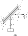
Fig 1] figure 1 , une représentation schématique d'un exemple d'un dispositif d'affichage tête haute, et - [
Fig 2] figure 2 , une représentation schématique vue en perspective d'un exemple de l'intérieur d'un véhicule comprenant le dispositif d'affichage tête haute de lafigure 1 . - Un dispositif 10 d'affichage tête haute est illustré par les
figures 1 et2 . - Comme illustré par la
figure 2 , le dispositif 10 est adapté à être intégré dans un véhicule 12. Le véhicule est, par exemple, un véhicule terrestre, aérien ou naval. Le véhicule terrestre est, par exemple, un véhicule automobile (figure 2 ) ou un véhicule ferroviaire. - Le dispositif 10 est propre à afficher des informations dans le champ de vision du conducteur 14 du véhicule 12. Les informations sont, par exemple, fournies par des instruments de bord du véhicule 12. A titre d'exemple, les informations sont relatives à un indicateur de vitesse du véhicule 12, à la consommation en énergie du véhicule 12, à des alarmes relatives au dysfonctionnement de certains composants du véhicule 12 ou encore à des informations de navigation (cartographie, positions, directions).
- Le dispositif 10 comprend un support transparent 20, un élément réflecteur 22 et une source de projection d'informations 24.
- Le support transparent 20 comprend un dioptre d'entrée 30 et un dioptre de sortie 32. Le dioptre d'entrée 30 à une face externe 30E et une face interne 30I opposée à la face externe 30E. Le dioptre de sortie 32 a une face externe 32E et une face interne 32I opposée à la face externe 32E. La face externe 30E, 32E de chaque dioptre 30, 32 est une face orientée vers l'extérieur dudit dioptre 30, 32, c'est-à-dire en direction du milieu extérieur (l'air). La face interne 30I, 32I de chaque dioptre 30, 32 est orientée vers l'intérieur dudit dioptre 30, 32.
- Le support transparent 20 comprend au moins une couche d'un matériau transparent entre le dioptre d'entrée 30 et le dioptre de sortie 32. Le matériau transparent est, par exemple, le verre ou le plastique.
- Dans un exemple de mise en oeuvre, le support transparent 20 comprend plusieurs couches de matériaux transparents, éventuellement différents, entre le dioptre d'entrée 30 et le dioptre de sortie 32. Les matériaux desdites couches sont, par exemple, le verre, l'éthylène vinyle acétate (EVA), ou encore le polyvinyle butyrale (PVB).
- Notamment, dans l'exemple illustré par la
figure 1 , le support transparent 20 comprend une première couche 34 de verre, une deuxième couche 36 de PVB et une troisième couche 38 de verre. Dans cet exemple, il est considéré que les indices des matériaux des différentes couches sont sensiblement identiques, et n'induisent pas de réflexions parasites additionnelles aux interfaces. - Le support transparent 20 est, par exemple, une lame aussi appelée « combineur » (en anglais « combiner »). En variante, le support transparent 20 est un parebrise, tel que le parebrise du véhicule 12 dans lequel est intégré le dispositif 10.
- L'élément réflecteur 22, aussi appelé polariseur réflectif, est un élément disposé sur au moins une partie de la face externe 30E du dioptre d'entrée 30. Par le terme « disposé », il est entendu que l'élément réflecteur 22 est appliqué (donc en contact) sur la face externe 30E du dioptre d'entrée 30, et adhère à cette face (éventuellement par un moyen de fixation). L'élément réflecteur 22 est, ainsi, solidaire de la face externe 30E du dioptre d'entrée 30. L'élément réflecteur 22 est, par exemple, un revêtement ou traitement (par exemple obtenu par dépôt physique ou dépôt chimique) ou un film (par exemple laminé ou maintenu par effet électrostatique).
- Lorsque le support transparent 20 est un pare-brise d'un véhicule, l'élément réflecteur 22 est avantageusement disposé sur toute la face externe 30E du dioptre d'entrée 30. Cela permet de rendre l'élément réflecteur 22 invisible pour l'utilisateur (pas d'effet patch).
- L'élément réflecteur 22 est un élément propre à réfléchir un faisceau lumineux incident FI ayant une gamme donnée de longueurs d'onde, en fonction de l'angle d'incidence Θi du faisceau incident FI sur l'élément réflecteur 22 et de la polarisation dudit faisceau incident FI.
- La gamme donnée de longueurs d'onde du faisceau incident FI appartient, par exemple, au domaine visible (380 nanomètres à 700 nanomètres).
- L'angle d'incidence Θi du faisceau incident FI est l'angle entre l'axe du faisceau et la normale N à l'élément réflecteur 22 au point d'incidence PI du faisceau incident FI sur l'élément réflecteur 22. L'axe du faisceau incident FI et la normale N à l'élément réflecteur 22 au point d'incidence PI définissent un plan d'incidence. Dans l'exemple illustré par la
figure 1 , le plan d'incidence est le plan de la figure. Notamment, l'élément réflecteur 22 est propre à, d'une part, réfléchir au moins une partie du faisceau incident FI pour former une image virtuelle utile observable depuis une fenêtre d'observation (correspondant à un faisceau utile FU) et à, d'autre part, transmettre au moins une autre partie du faisceau incident FI vers le dioptre de sortie 32. Le dioptre de sortie 32 est, le cas échéant, propre à réfléchir une partie du faisceau transmis par l'élément réflecteur 22 pour former une image virtuelle parasite observable depuis la fenêtre d'observation (correspondant à un faisceau parasite FP). - Dans ce qui suit, une polarisation rectiligne contenue dans le plan d'incidence est aussi appelée polarisation P, et une polarisation rectiligne perpendiculaire au plan d'incidence est aussi appelée polarisation S.
- L'élément réflecteur 22 est optimisé pour réfléchir une lumière de polarisation P. L'élément réflecteur 22 a, ainsi, une réflectivité plus grande, sur une gamme d'angles d'incidence et sur la gamme de longueurs d'onde donnée, pour une lumière de polarisation P que pour une lumière de polarisation différente (polarisation S, circulaire, elliptique).
- Avantageusement, la réflectivité de l'élément réflecteur 22 pour une lumière de polarisation P, sur la gamme d'angles d'incidence et sur la gamme de longueurs d'onde donnée, est choisie de sorte à être compatible avec les critères de transparence imposés aux parebrises de véhicules automobiles (pour que l'élément réflecteur 22 reste transparent et n'altère pas la perception du conducteur), tout en étant suffisamment élevée pour que l'effet « ghost » soit négligeable. A cet effet, l'élément réflecteur 22 est, par exemple, tel que le rapport signal sur bruit entre le faisceau utile et le faisceau parasite est inférieur ou égal à 3 pourcents, de préférence inférieur ou égal à 1 pourcent, avantageusement inférieur ou égal à 0,5 pourcents.
- De préférence, la réflectivité de l'élément réflecteur 22 pour une lumière de polarisation P, sur la gamme d'angles d'incidence et sur la gamme de longueurs d'onde donnée, est supérieure ou égale à 10 pourcents, de préférence supérieure ou égale à 15 pourcents, avantageusement supérieure ou égale à 20 pourcents, avantageusement supérieure ou égale à 40 pourcents.
- Avantageusement, la réflectivité de l'élément réflecteur 22 pour une lumière de polarisation différente d'une polarisation P, sur la gamme d'angles d'incidence et sur la gamme de longueurs d'onde donnée, est inférieure ou égale à 10 pourcents, de préférence inférieure ou égale à 5 pourcents.
- Avantageusement, la gamme d'angles d'incidence s'étend sur au moins 20 degrés, de préférence au moins 40 degrés, avantageusement au moins 60 degrés.
- De préférence, la gamme d'angles d'incidence Θi comprend l'angle de Brewster entre le milieu extérieur (air) et le support transparent au dioptre d'entrée (typiquement de 56° pour une interface air-verre). L'élément réflecteur 22 est en effet configuré pour rendre inexistant l'effet de l'angle de Brewster, c'est-à-dire que la polarisation P ne s'annule pas à l'angle de Brewster. Il est rappelé que l'angle de Brewster est l'angle d'incidence d'un faisceau incident sur un dioptre pour lequel le faisceau n'est pas réfléchi sur ce dioptre s'il est de polarisation P.
- L'élément réflecteur 22 comprend, par exemple, un empilement de couches diélectriques.
- L'élément réflecteur 22 est, par exemple, un polariseur ayant une réflectivité spécifique pour la lumière polarisée P, tel que décrit dans la demande de brevet
WO 96/19347 A - Notamment, l'élément réflecteur 22 comprend, par exemple, un film polymère multicouches comprenant des couches d'un polyester d'acide naphtalène dicarboxylique cristallin ou semi-cristallin, par exemple un 2,6-polyéthylène naphtalate ("PEN") ou un copolymère dérivé d'éthylène glycol, de naphtalène l'acide dicarboxylique et certains autres acides tels que le téréphtalate ("co-PEN"), avec un coefficient optique de contrainte positif, c'est-à-dire lors de l'étirement, son indice de réfraction dans la direction d'étirement augmente, ayant une épaisseur moyenne de pas de plus de 0,5 micron; et des couches d'un second polymère sélectionné, par exemple un polyéthylène téréphtalate ("PET") ou un co-PEN, ayant une épaisseur moyenne ne dépassant pas 0,5 micron.
- Dans un autre exemple, l'élément réflecteur 22 comprend un film polymère multicouches comprenant des couches d'un polyester cristallin ou semi-cristallin, par exemple un PET, ayant une épaisseur moyenne de pas plus de 0,5 micron; et des couches d'un second polymère sélectionné, par exemple un polyester ou un polystyrène, ayant une épaisseur moyenne de pas plus de 0,5 micron; dans lequel ledit film a été étiré dans au moins une direction jusqu'à au moins deux fois la dimension non étirée de cette direction.
- Dans un exemple de mise en oeuvre, l'élément réflecteur 22 présente également au moins un revêtement conférant des propriété optiques et/ou mécaniques additionnelles. Le revêtement est, par exemple, une protection thermique, un traitement colorimétrique neutralisant ou encore un revêtement anti-rayures ou antibuée.
- En complément ou en variante, l'élément réflecteur 22 est configuré de sorte à, sur la gamme d'angles d'incidence, réfléchir chacune d'une lumière polarisée P et d'une lumière polarisée S avec une forte réflectivité (typiquement supérieure ou égale à 50%) dans la gamme infrarouge (au moins infrarouge proche : 700 µm à 1 µm). Cela permet notamment de rejeter davantage de rayonnement solaire.
- La source de projection d'informations 24 est propre à émettre un faisceau lumineux incident sur l'élément réflecteur 22. Le faisceau incident FI transporte des informations qui sont, par exemple, telles que décrites précédemment.
- Le faisceau incident FI émis par la source de projection d'informations 24 est un faisceau polarisé selon une polarisation spécifique, dite polarisation principale.
- La polarisation principale est une polarisation rectiligne contenue dans le plan d'incidence, dite polarisation P. La polarisation principale est ainsi différente d'une polarisation S, d'une polarisation circulaire ou d'une polarisation elliptique.
- Les longueurs d'onde du faisceau incident FI sont dans la gamme de longueurs d'onde donnée pour l'élément réflecteur 22, typiquement dans le visible.
- La source de projection d'informations 24 est configurée de sorte que le faisceau incident FI arrive sur l'élément réflecteur 22 avec un angle d'incidence Θi compris dans la gamme d'angles d'incidence définie précédemment pour l'élément réflecteur 22.
- Avantageusement, la source de projection d'informations 24 est configurée pour envoyer le faisceau incident FI sur l'élément réflecteur 22 avec un angle d'incidence Θi tel que le faisceau transmis par l'élément réflecteur 22 arrive sur le dioptre de sortie 32 avec un angle sensiblement égal à l'angle de Brewster entre le milieu du support transparent 20 et le milieu extérieur (air) (typiquement de 33° pour une interface verre-air), ou dans une gamme d'angle s'étendant sur 10 degrés autour dudit angle de Brewster. Le faisceau incident étant de polarisation P, cela permet de supprimer complétement la réflexion parasite sur le dioptre de sortie 32.
- Le fonctionnement du dispositif 10 d'affichage tête haute va maintenant être décrit.
- Initialement, la source de projection d'informations 24 envoie un faisceau lumineux incident polarisé selon la polarisation principale en direction de l'élément réflecteur 22. Le faisceau incident FI est dans la gamme de longueurs d'onde donnée, typiquement dans le visible. Le faisceau incident FI arrive sur l'élément réflecteur 22 avec un angle d'incidence Θi par rapport à une normale N à l'élément réflecteur 22 au point d'incidence PI.
- L'élément réflecteur 22 réfléchit alors au moins une partie du faisceau incident FI pour former une image virtuelle utile observable depuis une fenêtre d'observation. Le faisceau incident FI étant de polarisation P et l'angle d'incidence Θi du faisceau sur l'élément réflecteur 22 étant compris dans la gamme d'angles d'incidence, la quantité de faisceau incident FI réfléchi est maximisée par rapport à un faisceau incident FI de polarisation S, et plus généralement de polarisation différente de P.
- L'élément réflecteur 22 transmet aussi au moins une autre partie du faisceau incident FI vers le dioptre de sortie 32.
- En fonction de l'angle d'incidence Θi, le dioptre de sortie 32 réfléchit ou non une partie du faisceau, transmis par l'élément réflecteur 22 et le dioptre d'entrée 30, pour former une image virtuelle parasite observable depuis la fenêtre d'observation.
- Lorsque tel est le cas, la quantité de lumière réfléchie sur le dioptre de sortie 32 est toutefois relativement faible. Par exemple, pour une polarisation principale de type P, la quantité de lumière réfléchie sur le dioptre de sortie 32 est typiquement de l'ordre de 1 à 2 pourcents pour un angle d'incidence Θi de 65 degrés. Par contre, si la polarisation principale était de type S, la quantité de lumière réfléchie sur le dioptre de sortie 32 serait plutôt de l'ordre de 20 pourcents pour un angle d'incidence Θi de 65 degrés.
- En outre, pour un angle d'incidence choisi de sorte que le faisceau transmis par l'élément réflecteur 22 arrive sur le dioptre de sortie 32 avec un angle sensiblement égal à l'angle de Brewster entre le milieu du support transparent 20 et le milieu extérieur (air), la quantité de lumière réfléchie sur le dioptre de sortie 32 est nulle ou quasi nulle (pas de réflexion parasite).
- Ainsi, le dispositif 10 d'affichage tête-haute permet de superposer des informations utiles à la conduite dans le champ de vision d'un conducteur.
- La combinaison d'un élément réflecteur 22, optimisé pour réfléchir une lumière de polarisation P, et d'une source de projection d'informations 24 émettant un faisceau lumineux polarisé selon une polarisation P, permet d'augmenter la quantité de lumière utile réfléchie par rapport à la quantité de lumière parasite réfléchie.
- En particulier, pour une polarisation P, le pourcentage de lumière parasite réfléchie est faible par rapport au pourcentage de lumière utile réfléchie, ce qui rend l'effet de « ghost » relativement négligeable. De plus, pour des angles d'incidence Θi choisis spécifiquement, le pourcentage de lumière parasite réfléchie est quasi nul, voir nul.
- Une polarisation P présente, en outre, l'avantage d'être compatible avec les verres solaires polarisés. De tels verres sont en effet classiquement configurés pour transmettre seulement la lumière polarisée P, et rejeter les autres types de polarisations.
- De plus, l'ajout d'un élément réflecteur 22 sur le support transparent 20 est simple à mettre en oeuvre puisque cela n'implique pas de modifier la structure du support 20, ni la ou les couches internes du support 20. L'élément réflecteur 22 a notamment la même configuration quelle que soit la structure du support transparent 20 (angle d'inclinaison, courbure), ce qui n'est pas le cas des solutions à prisme (wedge) de l'état de la technique. Ainsi, la fabrication du support transparent 20 n'est pas complexifiée et le dispositif 10 est adaptable à tous types de supports transparents, aussi bien des combineurs que des parebrises.
- L'homme du métier comprendra que les modes de réalisation décrits précédemment sont susceptibles d'être combinés entre eux lorsque de telles combinaisons sont compatibles.
- Les modes de réalisation décrits sont également adaptables avec une structure prismatique. Dans ce complément, le dioptre de sortie 32 est incliné par rapport au dioptre d'entrée 30 (« wedge ») de sorte à superposer l'image virtuelle parasite à l'image virtuelle utile. Un tel complément permet de limiter encore l'effet de « ghost » car l'image parasite déjà fortement atténuée par la configuration spécifique du dispositif 10 et en outre superposée à l'image utile.
Claims (10)
- Dispositif (10) d'affichage tête haute comprenant :a. un support transparent (20) comprenant un dioptre d'entrée (30) et un dioptre de sortie (32), chaque dioptre (30, 32) ayant une face externe (30E, 32E) et une face interne (30I, 32I) opposée à la face externe (30E, 32E),b. un élément réflecteur (22) disposé sur au moins une partie de la face externe (30E) du dioptre d'entrée (30),c. une source de projection d'informations (24) propre à émettre, en direction de l'élément réflecteur (22), un faisceau lumineux polarisé selon une polarisation principale, dit faisceau incident (FI), le faisceau incident (FI) arrivant sur l'élément réflecteur (22) avec un angle d'incidence (Θi) et définissant avec l'élément réflecteur (22) un plan d'incidence, la polarisation principale étant une polarisation contenue dans le plan d'incidence, dite polarisation P,l'élément réflecteur (22) ayant une plus grande réflectivité, sur une gamme d'angles d'incidence comprenant l'angle d'incidence (Θi), pour une lumière de polarisation P que pour une lumière de polarisation rectiligne perpendiculaire au plan d'incidence, dite polarisation S.
- Dispositif (10) selon la revendication 1, dans lequel l'élément réflecteur (22) a une plus grande réflectivité, sur la gamme d'angles d'incidence, pour une lumière de polarisation P que pour une lumière de polarisation différente.
- Dispositif (10) selon la revendication 1 ou 2, dans lequel la réflectivité de l'élément réflecteur (22) pour une lumière de polarisation P, sur la gamme d'angles d'incidence, est supérieure ou égale à 10 pourcents, de préférence supérieure ou égale à 15 pourcents, avantageusement supérieure ou égale à 20 pourcents, encore plus avantageusement supérieure ou égale à 40 pourcents.
- Dispositif (10) selon l'une quelconque des revendications 1 à 3, dans lequel la réflectivité de l'élément réflecteur (22) pour une lumière de polarisation différente d'une polarisation P, sur la gamme d'angles d'incidence, est inférieure ou égale à 10 pourcents, de préférence inférieure ou égale à 5 pourcents.
- Dispositif (10) selon l'une quelconque des revendications 1 à 4, dans lequel la gamme d'angles d'incidence s'étend sur au moins 20 degrés, de préférence au moins 40 degrés, avantageusement au moins 60 degrés.
- Dispositif (10) selon l'une quelconque des revendications 1 à 5, dans lequel la gamme d'angles d'incidence comprend un angle de Brewster relatif au dioptre d'entrée (30).
- Dispositif (10) selon l'une quelconque des revendications 1 à 6, dans lequel la source de projection d'informations (24) est configurée pour émettre le faisceau incident (FI) avec un angle d'incidence (Θi) choisi de sorte que la portion du faisceau incident transmis par l'élément réflecteur (22) arrive sur le dioptre de sortie (32) avec un angle sensiblement égal à l'angle de Brewster relatif au dioptre de sortie (32).
- Dispositif (10) selon l'une quelconque des revendications 1 à 7, dans lequel l'élément réflecteur (22) comprend un empilement de couches diélectriques.
- Dispositif (10) selon l'une quelconque des revendications 1 à 8, dans lequel le support transparent (20) est un pare-brise d'un véhicule, l'élément réflecteur (22) étant avantageusement disposé sur toute la face externe (30E) du dioptre d'entrée (30).
- Véhicule (12) comprenant un dispositif (10) d'affichage selon l'une quelconque des revendication 1 à 9.
Applications Claiming Priority (2)
| Application Number | Priority Date | Filing Date | Title |
|---|---|---|---|
| FR2011887A FR3116350B1 (fr) | 2020-11-19 | 2020-11-19 | Dispositif d'affichage tête haute |
| PCT/EP2021/082217 WO2022106577A1 (fr) | 2020-11-19 | 2021-11-18 | Dispositif d'affichage tête haute |
Publications (2)
| Publication Number | Publication Date |
|---|---|
| EP4248260A1 EP4248260A1 (fr) | 2023-09-27 |
| EP4248260B1 true EP4248260B1 (fr) | 2025-05-21 |
Family
ID=74758935
Family Applications (1)
| Application Number | Title | Priority Date | Filing Date |
|---|---|---|---|
| EP21814777.5A Active EP4248260B1 (fr) | 2020-11-19 | 2021-11-18 | Dispositif d'affichage tête haute |
Country Status (7)
| Country | Link |
|---|---|
| US (1) | US20240004191A1 (fr) |
| EP (1) | EP4248260B1 (fr) |
| JP (1) | JP7781158B2 (fr) |
| KR (1) | KR20230104178A (fr) |
| CN (1) | CN116490815A (fr) |
| FR (1) | FR3116350B1 (fr) |
| WO (1) | WO2022106577A1 (fr) |
Families Citing this family (1)
| Publication number | Priority date | Publication date | Assignee | Title |
|---|---|---|---|---|
| FR3116350B1 (fr) | 2020-11-19 | 2023-06-02 | Eyelights | Dispositif d'affichage tête haute |
Citations (11)
| Publication number | Priority date | Publication date | Assignee | Title |
|---|---|---|---|---|
| FR2011887A1 (fr) | 1968-06-01 | 1970-03-13 | Teves Gmbh Alfred | |
| WO1996019347A2 (fr) | 1994-12-20 | 1996-06-27 | Minnesota Mining And Manufacturing Company | Film optique multicouche |
| US20040008412A1 (en) | 2002-05-22 | 2004-01-15 | Yingqlu Jiang | Real image configuration for a high efficiency heads-up display (HUD) using a polarizing mirror and a polarization preserving screen |
| CN1732404A (zh) | 2002-12-31 | 2006-02-08 | 3M创新有限公司 | 带偏振光源与广角p偏振反射偏振镜的平视显示器 |
| WO2013190958A1 (fr) | 2012-06-22 | 2013-12-27 | 旭硝子株式会社 | Affichage tête haute |
| CN104267498A (zh) | 2014-10-14 | 2015-01-07 | 福耀玻璃工业集团股份有限公司 | 一种抬头显示系统 |
| CN204166197U (zh) | 2014-10-14 | 2015-02-18 | 福耀玻璃工业集团股份有限公司 | 一种抬头显示系统 |
| DE102014220189A1 (de) | 2014-10-06 | 2016-04-07 | Continental Automotive Gmbh | Head-Up-Display und Verfahren zur Erzeugung eines virtuellen Bilds mittels eines Head-Up-Displays |
| JP2018036499A (ja) | 2016-08-31 | 2018-03-08 | パイオニア株式会社 | 虚像表示装置 |
| FR3079314A1 (fr) | 2018-03-21 | 2019-09-27 | Valeo Comfort And Driving Assistance | Dispositif d'affichage tete haute |
| WO2022106577A1 (fr) | 2020-11-19 | 2022-05-27 | Eyelights | Dispositif d'affichage tête haute |
Family Cites Families (6)
| Publication number | Priority date | Publication date | Assignee | Title |
|---|---|---|---|---|
| FR2652936B1 (fr) * | 1989-10-06 | 1993-11-26 | Renault Regie Nale Usines | Dispositif de visualisation. |
| JP2958418B2 (ja) * | 1992-07-23 | 1999-10-06 | セントラル硝子株式会社 | 表示装置 |
| JP3453837B2 (ja) * | 1993-09-14 | 2003-10-06 | 株式会社デンソー | ヘッドアップディスプレイ |
| JP5101257B2 (ja) * | 2007-11-26 | 2012-12-19 | 株式会社東芝 | ヘッドアップディスプレイ用光学フィルム、ヘッドアップディスプレイ及び移動体 |
| TW201825323A (zh) * | 2017-01-13 | 2018-07-16 | 怡利電子工業股份有限公司 | 防疊影的反射裝置及其顯示系統 |
| CN107015369A (zh) * | 2017-06-06 | 2017-08-04 | 孝感市青谷信息科技有限公司 | 一种消重影抬头显示装置 |
-
2020
- 2020-11-19 FR FR2011887A patent/FR3116350B1/fr active Active
-
2021
- 2021-11-18 KR KR1020237016958A patent/KR20230104178A/ko active Pending
- 2021-11-18 EP EP21814777.5A patent/EP4248260B1/fr active Active
- 2021-11-18 JP JP2023530512A patent/JP7781158B2/ja active Active
- 2021-11-18 US US18/037,536 patent/US20240004191A1/en active Pending
- 2021-11-18 WO PCT/EP2021/082217 patent/WO2022106577A1/fr not_active Ceased
- 2021-11-18 CN CN202180077968.2A patent/CN116490815A/zh active Pending
Patent Citations (12)
| Publication number | Priority date | Publication date | Assignee | Title |
|---|---|---|---|---|
| FR2011887A1 (fr) | 1968-06-01 | 1970-03-13 | Teves Gmbh Alfred | |
| US5882774A (en) | 1993-12-21 | 1999-03-16 | Minnesota Mining And Manufacturing Company | Optical film |
| WO1996019347A2 (fr) | 1994-12-20 | 1996-06-27 | Minnesota Mining And Manufacturing Company | Film optique multicouche |
| US20040008412A1 (en) | 2002-05-22 | 2004-01-15 | Yingqlu Jiang | Real image configuration for a high efficiency heads-up display (HUD) using a polarizing mirror and a polarization preserving screen |
| CN1732404A (zh) | 2002-12-31 | 2006-02-08 | 3M创新有限公司 | 带偏振光源与广角p偏振反射偏振镜的平视显示器 |
| WO2013190958A1 (fr) | 2012-06-22 | 2013-12-27 | 旭硝子株式会社 | Affichage tête haute |
| DE102014220189A1 (de) | 2014-10-06 | 2016-04-07 | Continental Automotive Gmbh | Head-Up-Display und Verfahren zur Erzeugung eines virtuellen Bilds mittels eines Head-Up-Displays |
| CN104267498A (zh) | 2014-10-14 | 2015-01-07 | 福耀玻璃工业集团股份有限公司 | 一种抬头显示系统 |
| CN204166197U (zh) | 2014-10-14 | 2015-02-18 | 福耀玻璃工业集团股份有限公司 | 一种抬头显示系统 |
| JP2018036499A (ja) | 2016-08-31 | 2018-03-08 | パイオニア株式会社 | 虚像表示装置 |
| FR3079314A1 (fr) | 2018-03-21 | 2019-09-27 | Valeo Comfort And Driving Assistance | Dispositif d'affichage tete haute |
| WO2022106577A1 (fr) | 2020-11-19 | 2022-05-27 | Eyelights | Dispositif d'affichage tête haute |
Also Published As
| Publication number | Publication date |
|---|---|
| US20240004191A1 (en) | 2024-01-04 |
| JP7781158B2 (ja) | 2025-12-05 |
| KR20230104178A (ko) | 2023-07-07 |
| CN116490815A (zh) | 2023-07-25 |
| EP4248260A1 (fr) | 2023-09-27 |
| WO2022106577A1 (fr) | 2022-05-27 |
| FR3116350B1 (fr) | 2023-06-02 |
| FR3116350A1 (fr) | 2022-05-20 |
| JP2023550452A (ja) | 2023-12-01 |
Similar Documents
| Publication | Publication Date | Title |
|---|---|---|
| EP2961599B1 (fr) | Dispositif de visualisation pour vitrages transparents | |
| US20140307176A1 (en) | Light-Transmitting Pane for Displaying an Image of a Head-Up Display for Polarized Sunglasses | |
| JPH1096874A (ja) | 車両用ウインドシールドガラスおよびヘッドアップディスプレイ装置 | |
| JP2017538141A (ja) | ヘッドアップディスプレイシステム | |
| EP4248260B1 (fr) | Dispositif d'affichage tête haute | |
| US20180088326A1 (en) | Windshield head up display system | |
| US10416447B2 (en) | Windshield head up display system with waveplate | |
| WO2024115748A1 (fr) | Dispositif de contrôle d'un véhicule et véhicule associé | |
| KR101911488B1 (ko) | Hud용 윈드쉴드 부착형 컴바이너 | |
| EP2873992B1 (fr) | Système d'affichage d'une image sur un pare-brise | |
| FR3117070A1 (fr) | Panneau de contrôle d’un véhicule et véhicule associé | |
| FR3031399A1 (fr) | Dispositif de vision tete haute avec lame a surface reflechissante | |
| EP4210944A1 (fr) | Vitrage feuillete a reflexion lumineuse exterieure diminuee et affichage tete haute de visibilite amelioree | |
| WO2025248055A1 (fr) | Dispositif d'affichage tête haute | |
| FR3158069A1 (fr) | Dispositif interactif pour passager | |
| FR3130404A1 (fr) | Lame partiellement réfléchissante, dispositif d’affichage comprenant une telle lame, planche de bord et dispositif d’affichage tête-haute comprenant un tel dispositif d’affichage | |
| FR3156924A1 (fr) | Dispositif d’affichage tête haute pour un véhicule | |
| FR2915194A1 (fr) | Vitrage en verre feuillete et vehicule automobile comprenant un tel vitrage | |
| WO2025068539A1 (fr) | Panneau de contrôle d'un véhicule et véhicule associé | |
| EP4705132A1 (fr) | Elément de protection d'une unité d'émission d'informations de contrôle d'un véhicule | |
| FR3151551A3 (fr) | Arrangement lumineux pour véhicule automobile | |
| EP3848755A1 (fr) | Systeme de projection comprenant un vitrage pour ecran transparent | |
| FR3143139A1 (fr) | Dispositif de génération d’image et afficheur tête-haute comprenant un tel dispositif | |
| FR3161289A1 (fr) | Module réfléchissant transparent au radar, système et procédé de fabrication associés | |
| WO2020141173A1 (fr) | Film pour support de projection courbe d'un système d'affichage tête haute |
Legal Events
| Date | Code | Title | Description |
|---|---|---|---|
| STAA | Information on the status of an ep patent application or granted ep patent |
Free format text: STATUS: UNKNOWN |
|
| STAA | Information on the status of an ep patent application or granted ep patent |
Free format text: STATUS: THE INTERNATIONAL PUBLICATION HAS BEEN MADE |
|
| PUAI | Public reference made under article 153(3) epc to a published international application that has entered the european phase |
Free format text: ORIGINAL CODE: 0009012 |
|
| STAA | Information on the status of an ep patent application or granted ep patent |
Free format text: STATUS: REQUEST FOR EXAMINATION WAS MADE |
|
| 17P | Request for examination filed |
Effective date: 20230519 |
|
| AK | Designated contracting states |
Kind code of ref document: A1 Designated state(s): AL AT BE BG CH CY CZ DE DK EE ES FI FR GB GR HR HU IE IS IT LI LT LU LV MC MK MT NL NO PL PT RO RS SE SI SK SM TR |
|
| DAV | Request for validation of the european patent (deleted) | ||
| DAX | Request for extension of the european patent (deleted) | ||
| GRAP | Despatch of communication of intention to grant a patent |
Free format text: ORIGINAL CODE: EPIDOSNIGR1 |
|
| STAA | Information on the status of an ep patent application or granted ep patent |
Free format text: STATUS: GRANT OF PATENT IS INTENDED |
|
| TPAC | Observations filed by third parties |
Free format text: ORIGINAL CODE: EPIDOSNTIPA |
|
| INTG | Intention to grant announced |
Effective date: 20250130 |
|
| GRAS | Grant fee paid |
Free format text: ORIGINAL CODE: EPIDOSNIGR3 |
|
| GRAA | (expected) grant |
Free format text: ORIGINAL CODE: 0009210 |
|
| STAA | Information on the status of an ep patent application or granted ep patent |
Free format text: STATUS: THE PATENT HAS BEEN GRANTED |
|
| AK | Designated contracting states |
Kind code of ref document: B1 Designated state(s): AL AT BE BG CH CY CZ DE DK EE ES FI FR GB GR HR HU IE IS IT LI LT LU LV MC MK MT NL NO PL PT RO RS SE SI SK SM TR |
|
| REG | Reference to a national code |
Ref country code: GB Ref legal event code: FG4D Free format text: NOT ENGLISH |
|
| REG | Reference to a national code |
Ref country code: CH Ref legal event code: EP |
|
| REG | Reference to a national code |
Ref country code: DE Ref legal event code: R096 Ref document number: 602021031220 Country of ref document: DE |
|
| REG | Reference to a national code |
Ref country code: IE Ref legal event code: FG4D Free format text: LANGUAGE OF EP DOCUMENT: FRENCH |
|
| REG | Reference to a national code |
Ref country code: SE Ref legal event code: TRGR |
|
| REG | Reference to a national code |
Ref country code: NL Ref legal event code: MP Effective date: 20250521 |
|
| PG25 | Lapsed in a contracting state [announced via postgrant information from national office to epo] |
Ref country code: ES Free format text: LAPSE BECAUSE OF FAILURE TO SUBMIT A TRANSLATION OF THE DESCRIPTION OR TO PAY THE FEE WITHIN THE PRESCRIBED TIME-LIMIT Effective date: 20250521 Ref country code: PT Free format text: LAPSE BECAUSE OF FAILURE TO SUBMIT A TRANSLATION OF THE DESCRIPTION OR TO PAY THE FEE WITHIN THE PRESCRIBED TIME-LIMIT Effective date: 20250922 Ref country code: FI Free format text: LAPSE BECAUSE OF FAILURE TO SUBMIT A TRANSLATION OF THE DESCRIPTION OR TO PAY THE FEE WITHIN THE PRESCRIBED TIME-LIMIT Effective date: 20250521 |
|
| REG | Reference to a national code |
Ref country code: LT Ref legal event code: MG9D |
|
| PG25 | Lapsed in a contracting state [announced via postgrant information from national office to epo] |
Ref country code: NO Free format text: LAPSE BECAUSE OF FAILURE TO SUBMIT A TRANSLATION OF THE DESCRIPTION OR TO PAY THE FEE WITHIN THE PRESCRIBED TIME-LIMIT Effective date: 20250821 Ref country code: GR Free format text: LAPSE BECAUSE OF FAILURE TO SUBMIT A TRANSLATION OF THE DESCRIPTION OR TO PAY THE FEE WITHIN THE PRESCRIBED TIME-LIMIT Effective date: 20250822 |
|
| PG25 | Lapsed in a contracting state [announced via postgrant information from national office to epo] |
Ref country code: PL Free format text: LAPSE BECAUSE OF FAILURE TO SUBMIT A TRANSLATION OF THE DESCRIPTION OR TO PAY THE FEE WITHIN THE PRESCRIBED TIME-LIMIT Effective date: 20250521 Ref country code: NL Free format text: LAPSE BECAUSE OF FAILURE TO SUBMIT A TRANSLATION OF THE DESCRIPTION OR TO PAY THE FEE WITHIN THE PRESCRIBED TIME-LIMIT Effective date: 20250521 |
|
| PG25 | Lapsed in a contracting state [announced via postgrant information from national office to epo] |
Ref country code: BG Free format text: LAPSE BECAUSE OF FAILURE TO SUBMIT A TRANSLATION OF THE DESCRIPTION OR TO PAY THE FEE WITHIN THE PRESCRIBED TIME-LIMIT Effective date: 20250521 |
|
| PG25 | Lapsed in a contracting state [announced via postgrant information from national office to epo] |
Ref country code: HR Free format text: LAPSE BECAUSE OF FAILURE TO SUBMIT A TRANSLATION OF THE DESCRIPTION OR TO PAY THE FEE WITHIN THE PRESCRIBED TIME-LIMIT Effective date: 20250521 |
|
| PG25 | Lapsed in a contracting state [announced via postgrant information from national office to epo] |
Ref country code: RS Free format text: LAPSE BECAUSE OF FAILURE TO SUBMIT A TRANSLATION OF THE DESCRIPTION OR TO PAY THE FEE WITHIN THE PRESCRIBED TIME-LIMIT Effective date: 20250821 |
|
| PG25 | Lapsed in a contracting state [announced via postgrant information from national office to epo] |
Ref country code: IS Free format text: LAPSE BECAUSE OF FAILURE TO SUBMIT A TRANSLATION OF THE DESCRIPTION OR TO PAY THE FEE WITHIN THE PRESCRIBED TIME-LIMIT Effective date: 20250921 |
|
| PG25 | Lapsed in a contracting state [announced via postgrant information from national office to epo] |
Ref country code: LV Free format text: LAPSE BECAUSE OF FAILURE TO SUBMIT A TRANSLATION OF THE DESCRIPTION OR TO PAY THE FEE WITHIN THE PRESCRIBED TIME-LIMIT Effective date: 20250521 |
|
| REG | Reference to a national code |
Ref country code: AT Ref legal event code: MK05 Ref document number: 1797223 Country of ref document: AT Kind code of ref document: T Effective date: 20250521 |
|
| PGFP | Annual fee paid to national office [announced via postgrant information from national office to epo] |
Ref country code: DE Payment date: 20251117 Year of fee payment: 5 |
|
| PG25 | Lapsed in a contracting state [announced via postgrant information from national office to epo] |
Ref country code: SM Free format text: LAPSE BECAUSE OF FAILURE TO SUBMIT A TRANSLATION OF THE DESCRIPTION OR TO PAY THE FEE WITHIN THE PRESCRIBED TIME-LIMIT Effective date: 20250521 Ref country code: AT Free format text: LAPSE BECAUSE OF FAILURE TO SUBMIT A TRANSLATION OF THE DESCRIPTION OR TO PAY THE FEE WITHIN THE PRESCRIBED TIME-LIMIT Effective date: 20250521 Ref country code: DK Free format text: LAPSE BECAUSE OF FAILURE TO SUBMIT A TRANSLATION OF THE DESCRIPTION OR TO PAY THE FEE WITHIN THE PRESCRIBED TIME-LIMIT Effective date: 20250521 |
|
| PGFP | Annual fee paid to national office [announced via postgrant information from national office to epo] |
Ref country code: IT Payment date: 20251107 Year of fee payment: 5 |
|
| PGFP | Annual fee paid to national office [announced via postgrant information from national office to epo] |
Ref country code: FR Payment date: 20251010 Year of fee payment: 5 |
|
| PGFP | Annual fee paid to national office [announced via postgrant information from national office to epo] |
Ref country code: SE Payment date: 20251121 Year of fee payment: 5 |
|
| PG25 | Lapsed in a contracting state [announced via postgrant information from national office to epo] |
Ref country code: CZ Free format text: LAPSE BECAUSE OF FAILURE TO SUBMIT A TRANSLATION OF THE DESCRIPTION OR TO PAY THE FEE WITHIN THE PRESCRIBED TIME-LIMIT Effective date: 20250521 |
|
| PG25 | Lapsed in a contracting state [announced via postgrant information from national office to epo] |
Ref country code: EE Free format text: LAPSE BECAUSE OF FAILURE TO SUBMIT A TRANSLATION OF THE DESCRIPTION OR TO PAY THE FEE WITHIN THE PRESCRIBED TIME-LIMIT Effective date: 20250521 |
|
| PG25 | Lapsed in a contracting state [announced via postgrant information from national office to epo] |
Ref country code: SK Free format text: LAPSE BECAUSE OF FAILURE TO SUBMIT A TRANSLATION OF THE DESCRIPTION OR TO PAY THE FEE WITHIN THE PRESCRIBED TIME-LIMIT Effective date: 20250521 |
|
| REG | Reference to a national code |
Ref country code: DE Ref legal event code: R026 Ref document number: 602021031220 Country of ref document: DE |
|
| PLBI | Opposition filed |
Free format text: ORIGINAL CODE: 0009260 |
|
| REG | Reference to a national code |
Ref country code: CH Ref legal event code: L10 Free format text: ST27 STATUS EVENT CODE: U-0-0-L10-L00 (AS PROVIDED BY THE NATIONAL OFFICE) Effective date: 20260304 |
|
| PG25 | Lapsed in a contracting state [announced via postgrant information from national office to epo] |
Ref country code: RO Free format text: LAPSE BECAUSE OF FAILURE TO SUBMIT A TRANSLATION OF THE DESCRIPTION OR TO PAY THE FEE WITHIN THE PRESCRIBED TIME-LIMIT Effective date: 20250521 |
|
| PLAX | Notice of opposition and request to file observation + time limit sent |
Free format text: ORIGINAL CODE: EPIDOSNOBS2 |