EP4247706B1 - Sludge collecting unit - Google Patents
Sludge collecting unit Download PDFInfo
- Publication number
- EP4247706B1 EP4247706B1 EP21815926.7A EP21815926A EP4247706B1 EP 4247706 B1 EP4247706 B1 EP 4247706B1 EP 21815926 A EP21815926 A EP 21815926A EP 4247706 B1 EP4247706 B1 EP 4247706B1
- Authority
- EP
- European Patent Office
- Prior art keywords
- cartridge
- connection
- collecting unit
- pressure
- sludge collecting
- Prior art date
- Legal status (The legal status is an assumption and is not a legal conclusion. Google has not performed a legal analysis and makes no representation as to the accuracy of the status listed.)
- Active
Links
Images


Classifications
-
- B—PERFORMING OPERATIONS; TRANSPORTING
- B63—SHIPS OR OTHER WATERBORNE VESSELS; RELATED EQUIPMENT
- B63J—AUXILIARIES ON VESSELS
- B63J4/00—Arrangements of installations for treating ballast water, waste water, sewage, sludge, or refuse, or for preventing environmental pollution not otherwise provided for
- B63J4/004—Arrangements of installations for treating ballast water, waste water, sewage, sludge, or refuse, or for preventing environmental pollution not otherwise provided for for treating sludge, e.g. tank washing sludge
-
- F—MECHANICAL ENGINEERING; LIGHTING; HEATING; WEAPONS; BLASTING
- F02—COMBUSTION ENGINES; HOT-GAS OR COMBUSTION-PRODUCT ENGINE PLANTS
- F02B—INTERNAL-COMBUSTION PISTON ENGINES; COMBUSTION ENGINES IN GENERAL
- F02B77/00—Component parts, details or accessories, not otherwise provided for
- F02B77/04—Cleaning of, preventing corrosion or erosion in, or preventing unwanted deposits in, combustion engines
- F02B2077/045—Cleaning of, preventing corrosion or erosion in, or preventing unwanted deposits in, combustion engines by flushing or rinsing
Definitions
- the invention concerns the pressure-set sludge collection tank adapted to containing a barrel, such as a standard 208L (55 gallon) steel oil barrel.
- the invention is particularly suitable for use in the drainage systems that drain the rinsing air belts of engines, such as of the two-stroke crosshead kind. This is also referred to as" Scavenge air space" or "piston underside space”.
- the invention is also suitable for use in the drainage systems that drain from the flushing air tank of the engines, also referred to as "scavenge air receiver".
- the invention can be used both as retrofitting on existing engines and installations, as well as for installation on new engines and installations.
- the invention can be used both for pressure-set and for pressure less (open) sinks and piping systems.
- the present invention is especially relevant to be used in relation to engines on a ship but is not limited thereto.
- the medium consists mainly of lubricating oil mixed with solid particles in the form of unburned particles. These solid or sluggishly liquid constituents tend to precipitate / precipitate and accumulate by gravity at the bottom of pipes and containers, as well as tanks. This settles relatively quickly, layer upon layer, a relative heavy and solid material.
- the built-up material has almost the consistency of hard stamped soil. The phenomenon occurs because the flowing part of the medium (the oil) has a significant lower density than the solid particles of the sludge.
- the medium from the engine (mixture of lubricating oil and heavy solid particles) is passed through a falling pipe to an intermediate tank.
- This tank is usually referred to as a "Scavenging air drain tank”.
- This tank usually has a volume of approx. 500 - 2000L and is characterized by be designed to withstand overpressure corresponding to the purge air pressure of the engine (typically 0,2-4 bar). Air pressure from the engine (purge air) finds its way through sludge drain pipes and pressurizes the tank during engine operation.
- An example of such a system is shown in document US 6 058 917 A .
- the purpose of the tank is partly to collect and retain the medium's solid particles (sludge) and partly to function as a kind of observation tank where the daily drained volumes can be measured by sounding the tank. Furthermore, this tank is often provided with a level alarm which gives an alarm if the tank is filled above a desired level.
- This intermediate tank often is emptied daily by manually opening a valve to form a pipe connection from the bottom of the intermediate tank to a larger storage tank. The medium thus flows from the intermediate tank to the storage tank via gravity and positive pressure difference.
- This excavation of the intermediate tank often takes place at an interval of 2-4 weeks.
- the regular excavation is necessary to ensure the proper functioning of the system. If the excavation is not carried out in time, the sludge will reach a level where the pipe connection to the larger storage tank may clog. Then it becomes necessary to separate and clean both the intermediate tank and pipe connections.
- Sludge may be drained (see e.g. the published patent application WO2018/233789 ) and feed into a barrel.
- Standard barrels like the 208L (55 gallon) steel oil barrels, are not designed or constructed to withstand significantly under- or over-pressure. These standard barrels can therefore not withstand the overpressure (usually 0.2-4 bar) which occurs in the e.g. drainage systems on two-stroke engines of crosshead type. It is therefore not possible to connect a standard barrel directly to the drainage system allowing solid particles to settle in the barrel. It is therefore an object of the present invention to avoid deformation and damage or even bursting of the barrel
- the object of the invention is to prevent dirty manual excavation of the intermediate tank, as well as safe efficient separation of the lubricating oil and the heavy solid particles. This is achieved by the invention, where the relatively heavy particles settle directly in the transport barrel used for further transport of the solid. The invention results in drastic savings in man-hours used for manual cleaning.
- the invention could lead to a significant saving compared to consumption of cleaning chemicals and diesel oil consumed in connection with manual cleaning tanks and pipes. Furthermore, the invention prevents clogging of pipe systems from intermediate tank for storage tank. In addition, counteracting sludge precipitation in the large and hard-to-reach storage tanks. Unwanted precipitation / precipitation in these storage tanks, has historically forsaken extensive manual cleaning, as well as essential problems pumping the contents of the tank further. Last but not least, the invention entails greatly improved working environment, for the staff involved. It should be mentioned that plant with two-stroke engines of the crosshead type (ships) most often have ample empty steel barrels for availability.
- the invention is advantageous by being quickly mounted in the drainage system that drains from purge air belts and purge air tank on e.g. two-stroke engines of the crosshead type.
- the invention is further advantageous by having a standard 208L (55 gallon) steel drum surrounded by pressure tank.
- the invention is advantageous by allowing and collecting engine mud directly in standard cartridges such as 208L (55 gallon) steel drums, under pressure.
- the invention is also advantageous by having an arrangement for constant pressure equalization between inner and outer surface of the steel drum.
- the object of the invention includes a sludge collecting unit according to claim 1.
- the cartridge inner is connected to an engine purge air drain by an engine purge air drain connection to collect materials within the engine purge air drain, wherein the inner hollow is connected to the engine purge air drain connection by a pressure connection.
- the pressure tank may be adapted for an outlet of the cartridge to connected to the outside by a connection to the outside for overflow of fluid materials from the engine purge air drain.
- This enables the collection of the usable oil feed to the cartridge, and to this purpose the connection to the outside may be adapted to be connected in pressure tight communication to an intermediate tank for collecting the overflow fluid materials, or oil. It needs to be pressure tight not to affect the pressure equalization over the cartridge surface.
- the pressure connection connects to the engine purge at a position allowing gas air but substantially no solid or liquid materials to enter the pressure connection, and where the cartridge inner is connected at a position allowing solid / liquid materials to enter. This enables that the heavy sludge materials to be feed into the cartridge, whereas the volume of the inner hollow of the pressure tank outside the cartridge is essentially only allows gas to enter.
- One way to make such an arrangement is to make pressure connection connecting to an upper side of the engine purge air drain connection.
- the top cover may be formed with holes adapted for connection(s) to be connected to the cartridge in a pressure tight manner through the top cover.
- a tolerance is ensured by using inserted connections in the hole(s) adapted to be fixed to the cartridge.
- the insert connection may seal against the top cover using guide bushing also allow a horizontal and vertical movement during operation and installation of cartridge.
- the sludge collecting unit may comprise a positioning plate adapted to connect to the upper surface of the cartridge and the inner surface of the inner hollow.
- the positioning plate may have extensions adapted to reach to it cartridge side surface to fit between the cartridge outside surface and pressure tank inner surface. These could then ensure a non-rotation and could be adapted to fit into inner shapes formed in the inner surface of the pressure tank. Furthermore, this arrangement can maintain correct position of cartridge and ensure sufficient space for slide-in of cartridge lifting tool.
- the positioning plate may be formed with holes adapted to match the holes in the top cover to allow the connection to the cartridge through both the top cover and positioning plate.
- the top cover may be formed with an opening in communication to an overpressure valve positioned at the outside surface of the top cover.
- the engine purge air drain connection may be connected to the cartridge by an inlet connecting device also including a sensor piston formed with a sensor element to be positioned within the cartridge.
- the purpose of the sensor piston (14) is to allow depression below the top of the Barrel (8), e.g. by hand power.
- the sensor piston (14) will thus meet increased resistance when it encounters accumulated solid particles in the upper part of the barrel (8). In this way it can simply and safely be detected when the barrel (8) is filled with solid (precipitated) sludge.
- the sensor piston (14) will be held in upper position due to overpressure in barrel (8) inlet connection.
- the pressure tank may be adapted for a cartridge being a standard 208L (55 gallon) steel oil barrel.
- Fig. 1 shows an embodiment of a sludge collecting unit (SCU) (1) according to the present invention intended for pressurized drainage systems (drains from the engine flushing belts and containers), but it can also be used for collecting pressure-less sludge drainage systems.
- SCU sludge collecting unit
- the invention consists of a pressure tank (2) (possible being cylindrical or circular but could also be polygonal shaped) fitted with a top cover (3) that can be opened to a vertical position using a for example a hinged yoke (4) with handles.
- the hinged yoke (4) may be affected by two gas springs (5) or other means adapted to equalize the weight of the top cover (3), so that opening to the vertical position is easy and comfortable.
- the lifting yoke (4) may form an arrangement that enables the insertion of a safety split when the cover (3) is in the open position.
- the hinged yoke (4) could be replaced by any means adapted for a top cover (3) to be opened and closed.
- the top cove (3) is adapted to be fixed to the pressure tank (2) when in closed position e.g. by bolts or by other means.
- openings (15) are formed at the rim of respectively the upper opening of the pressure tank (2) and the top cover (3) for bolts to be inserted securing them together.
- the top cover (3) may also be provided with an overpressure valve (6) (see fig. 4 illustrating the overpressure valve (6) positioned at the outside of the top cover (3)) communicating with inner of the tank (2) by an opening (7).
- the pressure tank (2) is designed for a cartridge such as a barrel (8) (not visible in fig. 1 ) to fit into the tank (2), such as but not limited to a standard 208L (55 gallon) steel barrel or other standard cartridges, in the following in general referred to as barrels (8).
- the tank (2) is designed so that relatively minimal volume is between the barrel (8) outer surface the internal volume of the pressure tank (2). However, a certain tolerance is left so that slightly deformed (small bumps) barrels (8) can still be immersed in the pressure tank (2).
- the barrel (8) is kept centered and correctly positioned in the pressure tank (2) using a positioning plate (9), see also figs. 2 , 3A and 3B .
- the positioning plate (9) may be a flat plate adapted to fit into the inner upper barrel edge (8a) and having extensions (9a) adapted to reach over the upper barrel edge (8a) to it's outside, where it fits between the outside surface of the upper barrel edge (8a) and the inner surface of the pressure tank (2) to keep the barrel (8) tight in position.
- the extension may be adapted to fit into inner shapes (2a) formed in the inner surface of the pressure tank (2) to define an orientation of the barrel (8).
- Fig. 3A shows a side view of the barrel (8) inside the pressure tank (2) with the extension squeezed between the upper barrel edge (8a) and the inner surface of the pressure tank (2).
- 3B is a top view where the positioning plate (9) is positioned in connection to the barrel (8) and the pressure tank (2) showing an embodiment of the inner shapes (2a) formed as projections into the pressure tank (2) inner hollow but could also be recesses into the surface or formed in other suitable manners.
- the top cover (3) or the upper edge of the pressure tank (2) may be formed with a sealing (2b) adapted to be squeezed between the top cover (3) and upper edge of the pressure tank (2) when in closed position of the top cover (3). This ensures tight connection when they are fixed together e.g. by bolts.
- the top cover (3) and the positioning plate (9) are provided with holes (10, 11) so that access is created to the connections of the barrel (8) through the top cover (3) of the pressure tank (2).
- a tight fixing of the barrel (8) connections (e.g. being threaded) to the external connections (20a, 20b) through the top cover (3) may be ensured by inserted connections (not shown) possible threaded and adapted to be fixed to the barrel (8) connections, such as into threaded connection of the barrel (8), where standard oil barrels (8) as standard are fitted with 3 ⁇ 4 " and 2" internal pipe threads.
- the insert connections seal against the barrel (8) connections using sealing ring and possible seals against the top cover (3) using guide bushing with associated O-ring seals.
- the guide bushings further allow vertical movement of the barrel (8) connections and insert connections to compensate for vertical movement by heat expansion and smaller deformations of the barrel (8) due to pressure variations.
- the bushings may be tightened against the top cover (3) using flanges and bolts.
- the insert connection in connection to the (20b) connection to the outside of the barrel (8) may extend below the top of the barrel, such as e.g. 70mm. This allows lowering of the level in the barrel (8) before disassembling the insert connection etc. to avoid spillage of oil during barrel (8) replacement.
- Fig. 4 is a top view of the cover plate (3) showing a handle (3a) and respectively an engine purge air drain connection (20a) and a connection for the outside of the barrel for oil outlet (20b), where both connections could be pipes, hoses etc.
- Inlet of medium occurs through the engine purge air drain connection (20a) connected to an inlet connection of the barrel (8) by a connected hole in the top cover (10) and hole in the positioning plate (11).
- an inlet connecting device (13) possibly Y-shaped e.g. a 45 degree pipe-Y
- This design ensures functional inlet to the barrel, at the same time allows to access the interior of the barrel (8) of a sensor piston (14).
- the sensor piston (14) could be made with a pressure-tight shaft seal allowing effortless axial (vertical) movement of a sensor element within the barrel (8).
- the purpose of the sensor piston (14) is to allow depression below the top of the Barrel (8), e.g. by hand power.
- the sensor piston (14) will thus meet increased resistance when it encounters accumulated solid particles in the upper part of the barrel (8). In this way it can simply and safely be detected when the barrel (8) is filled with solid (precipitated) sludge.
- the sensor piston (14) will be held in upper position due to overpressure in barrel (8) inlet connection. This overpressure is created by air pressure from the engine purge air system which propagates to the barrel (8) via the drainage system.
- the invention ensures an approximately uniform pressure on the inside /outside of the barrel (8).
- the inside of the barrel (8) volume is pressure-tight connected to the engine purge air drain connection (20a).
- This fills the barrel (8) quickly with liquid medium by continuous drainage from the engine.
- Relatively pure lubricating oil thus is pushed and flows by the overflow and gravity from the pressure tank (2) to the intermediate tank where it is collected as relatively pure oil possible to use for other purposes.
- the relatively heavy particles (sludge) precipitate in the barrel (8) layer by layer.
- the empty volume between the inside of the pressure tank (2) and the outside of the barrel (8) is also pressurized with pressure equalization air (engine flush air) via a pressure connection (21) and a pressure opening (12) in the pressure tank (2) to the inside hollow but outside of the barrel (8), see also fig. 3A , e.g. to a top side of the engine drain connection (20a), thus ensuring the same pressure at the outside of the barrel (8) as the inside.
- pressure equalization air engine flush air
- the pressure equalization air may be led through an oil mist filter for purifying the air of oil vapors to avoid unnecessary soiling of the outside of the barrel (8). Separated oil mist may be drained manually from oil mist filter through a valve in the bottom of the filter.
- the pressure tank (2) is also fitted with a drain connection and valve at the bottom. This enables draining of liquid if the pressure tank (2) is being washed at the inside.
- the barrel is easily replaced by the following procedure:
- the system is depressurized, this is achieved by closing the main valve from the engine drainage system.
- An opening possibly throttled, and possible the opening (7) (see fig. 1 ) for the overpressure valve (6) (see fig. 4 )) to the atmosphere ensures rapid venting of overpressure from the intermediate tank the pressure tank (2) and the connections (20a, 20b).
- connection (20a, 20b), guide bushings and connecting inserts are disconnected, and the top cover (3) opened securely to the vertical position.
- the barrel (8) is closed securely with the suitable plugs, these usually being threaded standard parts.
- a special and approved lifting tool can then be lowered around the barrel (8) Upper edge (8a), and the lifting tool slide down into the space between the barrel (8) and the pressure tank (2).
- the lifting tool is designed so that it clamps around the barrel (8) at the same time as the barrel (8) is lifted.
- the barrel is hereby lifted out of the pressure tank (2) using a crane or hoist.
Landscapes
- Engineering & Computer Science (AREA)
- Health & Medical Sciences (AREA)
- Environmental & Geological Engineering (AREA)
- General Health & Medical Sciences (AREA)
- Public Health (AREA)
- Toxicology (AREA)
- Chemical & Material Sciences (AREA)
- Combustion & Propulsion (AREA)
- Mechanical Engineering (AREA)
- Ocean & Marine Engineering (AREA)
- Lubrication Details And Ventilation Of Internal Combustion Engines (AREA)
Description
- The invention concerns the pressure-set sludge collection tank adapted to containing a barrel, such as a standard 208L (55 gallon) steel oil barrel. The invention is particularly suitable for use in the drainage systems that drain the rinsing air belts of engines, such as of the two-stroke crosshead kind. This is also referred to as" Scavenge air space" or "piston underside space". The invention is also suitable for use in the drainage systems that drain from the flushing air tank of the engines, also referred to as "scavenge air receiver". The invention can be used both as retrofitting on existing engines and installations, as well as for installation on new engines and installations. The invention can be used both for pressure-set and for pressure less (open) sinks and piping systems.
- The present invention is especially relevant to be used in relation to engines on a ship but is not limited thereto.
- It is known from e.g. two-stroke engines of the crosshead type that during operation varying amounts of the medium called sludge is generated. The medium consists mainly of lubricating oil mixed with solid particles in the form of unburned particles. These solid or sluggishly liquid constituents tend to precipitate / precipitate and accumulate by gravity at the bottom of pipes and containers, as well as tanks. This settles relatively quickly, layer upon layer, a relative heavy and solid material. The built-up material has almost the consistency of hard stamped soil. The phenomenon occurs because the flowing part of the medium (the oil) has a significant lower density than the solid particles of the sludge.
- It is known that the medium from the engine (mixture of lubricating oil and heavy solid particles) is passed through a falling pipe to an intermediate tank. This tank is usually referred to as a "Scavenging air drain tank". This tank usually has a volume of approx. 500 - 2000L and is characterized by be designed to withstand overpressure corresponding to the purge air pressure of the engine (typically 0,2-4 bar). Air pressure from the engine (purge air) finds its way through sludge drain pipes and pressurizes the tank during engine operation. An example of such a system is shown in document
US 6 058 917 A . - The purpose of the tank is partly to collect and retain the medium's solid particles (sludge) and partly to function as a kind of observation tank where the daily drained volumes can be measured by sounding the tank. Furthermore, this tank is often provided with a level alarm which gives an alarm if the tank is filled above a desired level. This intermediate tank often is emptied daily by manually opening a valve to form a pipe connection from the bottom of the intermediate tank to a larger storage tank. The medium thus flows from the intermediate tank to the storage tank via gravity and positive pressure difference.
- With this well-known and widely used system, regular manual cleaning thus is required of the intermediate tank. The intermediate tank must simply be opened by removing a manhole cover to the tank. This is followed by a cumbersome and dirty manual excavation of the tank by hand. Excavation of solid particles (sludge) usually takes place using different manufactured shovels and scrapers. The sludge is dug into buckets, which are usually hoisted by hand up to the nearest deck (when on a ship). Here the sludge is often poured into open 208L steel barrels. After the excavation is completed, the tank is manually cleaned with cloths. It is often necessary to crawl into the tank to achieve sufficient cleaning. The manual excavation and cleaning are associated with potential harmful work. The working positions are also often uncomfortable and incorrect by today's standards. This excavation of the intermediate tank often takes place at an interval of 2-4 weeks. The regular excavation is necessary to ensure the proper functioning of the system. If the excavation is not carried out in time, the sludge will reach a level where the pipe connection to the larger storage tank may clog. Then it becomes necessary to separate and clean both the intermediate tank and pipe connections.
- A distinction is made between the liquid part of the medium (lubricating oil) and the solid constituents (sludge). Both parts are transported for processing at approved companies. The lubricating oil often has a value and a payment often is received as it can be used relatively easily for other purposes.
- On the other hand, a high price is to be paid for the solid particles (sludge) by weight, as it is cumbersome to handle, and an efficient separation between sludge and lubricating oil therefore is an advantage to avoid high taxes are not to be paid for an unnecessarily high content of lubricating oil in the sludge.
- Sludge may be drained (see e.g. the published patent application
WO2018/233789 ) and feed into a barrel. Standard barrels like the 208L (55 gallon) steel oil barrels, are not designed or constructed to withstand significantly under- or over-pressure. These standard barrels can therefore not withstand the overpressure (usually 0.2-4 bar) which occurs in the e.g. drainage systems on two-stroke engines of crosshead type. It is therefore not possible to connect a standard barrel directly to the drainage system allowing solid particles to settle in the barrel. It is therefore an object of the present invention to avoid deformation and damage or even bursting of the barrel - The object of the invention is to prevent dirty manual excavation of the intermediate tank, as well as safe efficient separation of the lubricating oil and the heavy solid particles. This is achieved by the invention, where the relatively heavy particles settle directly in the transport barrel used for further transport of the solid. The invention results in drastic savings in man-hours used for manual cleaning.
- In addition, the invention could lead to a significant saving compared to consumption of cleaning chemicals and diesel oil consumed in connection with manual cleaning tanks and pipes. Furthermore, the invention prevents clogging of pipe systems from intermediate tank for storage tank. In addition, counteracting sludge precipitation in the large and hard-to-reach storage tanks. Unwanted precipitation / precipitation in these storage tanks, has historically forsaken extensive manual cleaning, as well as essential problems pumping the contents of the tank further. Last but not least, the invention entails greatly improved working environment, for the staff involved. It should be mentioned that plant with two-stroke engines of the crosshead type (ships) most often have ample empty steel barrels for availability. This is due to a relatively high consumption of lubricating oil, which is supplied in these standard 208l barrels. There are no known systems where sludge from e.g. two-stroke engine purge air drainage systems can sedimented and collected directly in standard 208L (55 gallon) steel drums under pressure.
- The invention is advantageous by being quickly mounted in the drainage system that drains from purge air belts and purge air tank on e.g. two-stroke engines of the crosshead type. The invention is further advantageous by having a standard 208L (55 gallon) steel drum surrounded by pressure tank. Furthermore, the invention is advantageous by allowing and collecting engine mud directly in standard cartridges such as 208L (55 gallon) steel drums, under pressure. The invention is also advantageous by having an arrangement for constant pressure equalization between inner and outer surface of the steel drum.
- The object of the invention includes a sludge collecting unit according to
claim 1. - This ensures the same pressure at both sides of the cartridge. Therefore, the cartridge inner is connected to an engine purge air drain by an engine purge air drain connection to collect materials within the engine purge air drain, wherein the inner hollow is connected to the engine purge air drain connection by a pressure connection.
- The pressure tank may be adapted for an outlet of the cartridge to connected to the outside by a connection to the outside for overflow of fluid materials from the engine purge air drain. This enables the collection of the usable oil feed to the cartridge, and to this purpose the connection to the outside may be adapted to be connected in pressure tight communication to an intermediate tank for collecting the overflow fluid materials, or oil. It needs to be pressure tight not to affect the pressure equalization over the cartridge surface.
- The pressure connection connects to the engine purge at a position allowing gas air but substantially no solid or liquid materials to enter the pressure connection, and where the cartridge inner is connected at a position allowing solid / liquid materials to enter. This enables that the heavy sludge materials to be feed into the cartridge, whereas the volume of the inner hollow of the pressure tank outside the cartridge is essentially only allows gas to enter. One way to make such an arrangement is to make pressure connection connecting to an upper side of the engine purge air drain connection.
- The top cover may be formed with holes adapted for connection(s) to be connected to the cartridge in a pressure tight manner through the top cover.
- To allow for variations in e.g. the heights of the different cartridges inserted, a tolerance is ensured by using inserted connections in the hole(s) adapted to be fixed to the cartridge. The insert connection may seal against the top cover using guide bushing also allow a horizontal and vertical movement during operation and installation of cartridge.
- To ensure a correct positioning and fixing the pressure tank within the inner hollow, the sludge collecting unit may comprise a positioning plate adapted to connect to the upper surface of the cartridge and the inner surface of the inner hollow.
- The positioning plate may have extensions adapted to reach to it cartridge side surface to fit between the cartridge outside surface and pressure tank inner surface. These could then ensure a non-rotation and could be adapted to fit into inner shapes formed in the inner surface of the pressure tank. Furthermore, this arrangement can maintain correct position of cartridge and ensure sufficient space for slide-in of cartridge lifting tool.
- The positioning plate may be formed with holes adapted to match the holes in the top cover to allow the connection to the cartridge through both the top cover and positioning plate.
- In order to control the pressure within the pressure tank, the top cover may be formed with an opening in communication to an overpressure valve positioned at the outside surface of the top cover.
- The engine purge air drain connection may be connected to the cartridge by an inlet connecting device also including a sensor piston formed with a sensor element to be positioned within the cartridge. The purpose of the sensor piston (14) is to allow depression below the top of the Barrel (8), e.g. by hand power. The sensor piston (14) will thus meet increased resistance when it encounters accumulated solid particles in the upper part of the barrel (8). In this way it can simply and safely be detected when the barrel (8) is filled with solid (precipitated) sludge. During operation, the sensor piston (14) will be held in upper position due to overpressure in barrel (8) inlet connection.
- The pressure tank may be adapted for a cartridge being a standard 208L (55 gallon) steel oil barrel.
-
- Fig. 1
- Pressure tank for a sludge collecting unit according to an embodiment of the present invention.
- Fig. 2
- Top view of a positioning plate embodiment as part of the sludge collecting unit.
- Fig. 3A,B
- Respectively side view and top view of the pressure tank with a cartridge positioned within and with a positioning plate.
- Fig. 4
- Top view of the pressure tank with closed top cover.
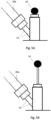
- Figs. 5A, B
- A inlet connecting devices attached to the top cover of the pressure tank for connection of an engine purge air drain connection and with a sensor piston at two different positions.
- It should be understood that the detailed description and specific examples, while indicating embodiments of the invention, are given by way of illustration only.
-
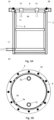
Fig. 1 shows an embodiment of a sludge collecting unit (SCU) (1) according to the present invention intended for pressurized drainage systems (drains from the engine flushing belts and containers), but it can also be used for collecting pressure-less sludge drainage systems. - The invention consists of a pressure tank (2) (possible being cylindrical or circular but could also be polygonal shaped) fitted with a top cover (3) that can be opened to a vertical position using a for example a hinged yoke (4) with handles. The hinged yoke (4) may be affected by two gas springs (5) or other means adapted to equalize the weight of the top cover (3), so that opening to the vertical position is easy and comfortable. The lifting yoke (4) may form an arrangement that enables the insertion of a safety split when the cover (3) is in the open position. The hinged yoke (4) could be replaced by any means adapted for a top cover (3) to be opened and closed.
- The top cove (3) is adapted to be fixed to the pressure tank (2) when in closed position e.g. by bolts or by other means. In the illustrated embodiment openings (15) are formed at the rim of respectively the upper opening of the pressure tank (2) and the top cover (3) for bolts to be inserted securing them together.
- The top cover (3) may also be provided with an overpressure valve (6) (see
fig. 4 illustrating the overpressure valve (6) positioned at the outside of the top cover (3)) communicating with inner of the tank (2) by an opening (7). This ensures that the pressure in the pressure tank cannot exceed a design pressure or set maximum pressure. The pressure tank (2) is designed for a cartridge such as a barrel (8) (not visible infig. 1 ) to fit into the tank (2), such as but not limited to a standard 208L (55 gallon) steel barrel or other standard cartridges, in the following in general referred to as barrels (8). The tank (2) is designed so that relatively minimal volume is between the barrel (8) outer surface the internal volume of the pressure tank (2). However, a certain tolerance is left so that slightly deformed (small bumps) barrels (8) can still be immersed in the pressure tank (2). - The barrel (8) is kept centered and correctly positioned in the pressure tank (2) using a positioning plate (9), see also
figs. 2 ,3A and 3B . - The positioning plate (9), see a top view of an embodiment in
fig. 2 , may be a flat plate adapted to fit into the inner upper barrel edge (8a) and having extensions (9a) adapted to reach over the upper barrel edge (8a) to it's outside, where it fits between the outside surface of the upper barrel edge (8a) and the inner surface of the pressure tank (2) to keep the barrel (8) tight in position. In addition, the extension may be adapted to fit into inner shapes (2a) formed in the inner surface of the pressure tank (2) to define an orientation of the barrel (8).Fig. 3A shows a side view of the barrel (8) inside the pressure tank (2) with the extension squeezed between the upper barrel edge (8a) and the inner surface of the pressure tank (2).Fig. 3B is a top view where the positioning plate (9) is positioned in connection to the barrel (8) and the pressure tank (2) showing an embodiment of the inner shapes (2a) formed as projections into the pressure tank (2) inner hollow but could also be recesses into the surface or formed in other suitable manners. - The top cover (3) or the upper edge of the pressure tank (2) (as illustrated) may be formed with a sealing (2b) adapted to be squeezed between the top cover (3) and upper edge of the pressure tank (2) when in closed position of the top cover (3). This ensures tight connection when they are fixed together e.g. by bolts.
- The top cover (3) and the positioning plate (9) are provided with holes (10, 11) so that access is created to the connections of the barrel (8) through the top cover (3) of the pressure tank (2). In one embodiment, a tight fixing of the barrel (8) connections (e.g. being threaded) to the external connections (20a, 20b) through the top cover (3) may be ensured by inserted connections (not shown) possible threaded and adapted to be fixed to the barrel (8) connections, such as into threaded connection of the barrel (8), where standard oil barrels (8) as standard are fitted with ¾ " and 2" internal pipe threads.
- The insert connections seal against the barrel (8) connections using sealing ring and possible seals against the top cover (3) using guide bushing with associated O-ring seals. The guide bushings further allow vertical movement of the barrel (8) connections and insert connections to compensate for vertical movement by heat expansion and smaller deformations of the barrel (8) due to pressure variations.
- Some vertical and horizontal tolerance is needed to compensate for smaller height differences according to the manufacturing tolerances of e.g. standard barrels (8).
- The bushings may be tightened against the top cover (3) using flanges and bolts.
- The insert connection in connection to the (20b) connection to the outside of the barrel (8) (related to oil outlet (overflow) from the barrel (8)), may extend below the top of the barrel, such as e.g. 70mm. This allows lowering of the level in the barrel (8) before disassembling the insert connection etc. to avoid spillage of oil during barrel (8) replacement.
-
Fig. 4 is a top view of the cover plate (3) showing a handle (3a) and respectively an engine purge air drain connection (20a) and a connection for the outside of the barrel for oil outlet (20b), where both connections could be pipes, hoses etc. - Inlet of medium (lubricating oil mixed with relatively heavy solid particles) occurs through the engine purge air drain connection (20a) connected to an inlet connection of the barrel (8) by a connected hole in the top cover (10) and hole in the positioning plate (11). At the top of the cover plate (3) an inlet connecting device (13) (possible Y-shaped e.g. a 45 degree pipe-Y) (see
fig. 5A and 5B ) connecting the engine purge air drain connection (20a) to the inlet connection of the barrel (8). This design ensures functional inlet to the barrel, at the same time allows to access the interior of the barrel (8) of a sensor piston (14). The sensor piston (14) could be made with a pressure-tight shaft seal allowing effortless axial (vertical) movement of a sensor element within the barrel (8). The purpose of the sensor piston (14) is to allow depression below the top of the Barrel (8), e.g. by hand power. The sensor piston (14) will thus meet increased resistance when it encounters accumulated solid particles in the upper part of the barrel (8). In this way it can simply and safely be detected when the barrel (8) is filled with solid (precipitated) sludge. During operation, the sensor piston (14) will be held in upper position due to overpressure in barrel (8) inlet connection. This overpressure is created by air pressure from the engine purge air system which propagates to the barrel (8) via the drainage system. - The invention ensures an approximately uniform pressure on the inside /outside of the barrel (8). The inside of the barrel (8) volume is pressure-tight connected to the engine purge air drain connection (20a). This fills the barrel (8) quickly with liquid medium by continuous drainage from the engine. There will be an overflow of lubricating oil to an intermediate tank connected to the outlet of the barrel (8) by of the connection (20b) to the outside of the barrel (8). In the intermediate tank in same pressure prevails as in the pressure tank (2), respectively the drain connection (20a). Relatively pure lubricating oil thus is pushed and flows by the overflow and gravity from the pressure tank (2) to the intermediate tank where it is collected as relatively pure oil possible to use for other purposes. The relatively heavy particles (sludge) precipitate in the barrel (8) layer by layer.
- The empty volume between the inside of the pressure tank (2) and the outside of the barrel (8) is also pressurized with pressure equalization air (engine flush air) via a pressure connection (21) and a pressure opening (12) in the pressure tank (2) to the inside hollow but outside of the barrel (8), see also
fig. 3A , e.g. to a top side of the engine drain connection (20a), thus ensuring the same pressure at the outside of the barrel (8) as the inside. By positioning the connection at the top side of the engine drain connection (20a) it is ensured that the heavy substances like the sludge will not enter thepressure connection 21. An effectively equalization of the pressure difference on the inside / outside of the barrel (8) thus is ensured. Therefore, the same pressure always prevails on the inside and outside of the barrel (8), even at a varying pressure in the engine drainage system. The pressure equalization air may be led through an oil mist filter for purifying the air of oil vapors to avoid unnecessary soiling of the outside of the barrel (8). Separated oil mist may be drained manually from oil mist filter through a valve in the bottom of the filter. The pressure tank (2) is also fitted with a drain connection and valve at the bottom. This enables draining of liquid if the pressure tank (2) is being washed at the inside. - The barrel is easily replaced by the following procedure:
The system is depressurized, this is achieved by closing the main valve from the engine drainage system. An opening (possible throttled, and possible the opening (7) (seefig. 1 ) for the overpressure valve (6) (seefig. 4 )) to the atmosphere ensures rapid venting of overpressure from the intermediate tank the pressure tank (2) and the connections (20a, 20b). - Subsequently the connections (20a, 20b), guide bushings and connecting inserts are disconnected, and the top cover (3) opened securely to the vertical position. The barrel (8) is closed securely with the suitable plugs, these usually being threaded standard parts.
- A special and approved lifting tool can then be lowered around the barrel (8) Upper edge (8a), and the lifting tool slide down into the space between the barrel (8) and the pressure tank (2). The lifting tool is designed so that it clamps around the barrel (8) at the same time as the barrel (8) is lifted. The barrel is hereby lifted out of the pressure tank (2) using a crane or hoist.
- Installation of new empty barrel (8) takes place mainly in reverse order.
-
- 1 - Sludge collecting unit (SCU).
- 2 - Pressure tank
- 2a - Inner shapes in the pressure tank
- 2b - Sealing
- 3 - Top cover
- 3a - Handle
- 4 - Hinged yoke
- 5 - Gas springs or other means adapted to equalize the weight of the top cover
- 6 - Overpressure valve
- 7 - Opening for overpressure valve
- 8 - Barrel
- 8a - Upper barrel edge
- 9 - Positioning plate
- 9a - Extensions of the positioning plate
- 10 - Holes in the top cover
- 11 - Holes in the positioning plate
- 12 - Pressure opening
- 13 - Inlet connecting device - Y-shaped
- 14 - Sensor piston
- 15 - Openings for bolts
- 20a - Engine purge air drain connection ((pipe, hoses etc.)
- 20b - Connection to the outside of the barrel for oil outlet
- 21 - Pressure connection
Claims (14)
- A sludge collecting unit comprising a pressure tank (2) with an inner hollow and a top cover (3) adapted to make a pressure tight closure of the inner hollow, whereinthe pressure tank (2) is adapted for a cartridge (8) to be inserted and enclosed within the inner hollow with the cartridge (8) inner and the pressure tank (2) inner hollow both connected (10, 11, 12, 20a, 21) to an engine purge air drain,wherein the cartridge (8) inner is connected (10, 11, 20a) to an engine purge air drain by an engine purge air drain connection (20a) to collect materials within the engine purge air drain, wherein the inner hollow is connected to the engine purge air drain connection (20a) by a pressure connection (12, 21),where the cartridge (8) inner is connected (10, 11, 20a) at a position allowing solid materials to enter, characterized in that the pressure connection (12, 21) connects to the engine purge at a position allowing gas air but substantially no solid materials to enter the pressure connection (12, 21).
- A sludge collecting unit according to claim 1, wherein the pressure tank (2) is adapted for an outlet of the cartridge (8) to connected to the outside by a connection to the outside (20b) for overflow of fluid materials from the engine purge air drain.
- A sludge collecting unit according to claim 2, wherein the connection to the outside (20b) is adapted to be connected in pressure tight communication to an intermediate tank for collecting the overflow fluid materials.
- A sludge collecting unit according to any of the preceding claims, wherein the pressure connection (12, 21) connects to an upper side of the engine purge air drain connection (20a).
- A sludge collecting unit according to any of the preceding claims, where the top cover (3) is formed with holes (10) adapted for connection(s) (20a, 20b) to be connected to the cartridge (8) in a pressure tight manner through the top cover (3).
- A sludge collecting unit according to claim 5, wherein the connection(s) (20a, 20b) to the cartridge (8) is through inserted connections in the hole(s) (10) adapted to be fixed to the cartridge (8).
- A sludge collecting unit according to claim 6, wherein the insert connection seal against the top cover (3) using guide bushing.
- A sludge collecting unit according to any of the previous claims, wherein the unit comprises a positioning plate (9) adapted to connect to the upper surface of the cartridge (8) and the inner surface of the inner hollow.
- A sludge collecting unit according to claim 8, wherein the positioning plate (9) has extensions (9a) adapted to reach to it cartridge (8) side surface to fit between the cartridge (8) outside surface and pressure tank (2) inner surface.
- A sludge collecting unit according to claim 9, wherein the extensions (9a) are adapted to fit into inner shapes (2a) formed in the inner surface of the pressure tank (2).
- A sludge collecting unit according to claim 4 and claim 8, 9 or 10, wherein the positioning plate (9) is formed with holes (11) adapted to match the holes (10) in the top cover (3).
- A sludge collecting unit according to any of the previous claims, wherein the top cover (3) is formed with an opening (7) in communication to an overpressure valve (6) positioned at the outside surface of the top cover (3).
- A sludge collecting unit according to any of the previous claims, wherein the engine purge air drain connection (20a) is connected to the cartridge (8) by an inlet connecting device (13) also including a sensor piston (14) formed with a sensor element to be positioned within the cartridge (8).
- A sludge collecting unit according to any of the previous claims, wherein the pressure tank (2) is adapted for a cartridge (8) being a standard 208L (55 gallon) steel oil barrel.
Applications Claiming Priority (2)
| Application Number | Priority Date | Filing Date | Title |
|---|---|---|---|
| DKPA202001294 | 2020-11-17 | ||
| PCT/EP2021/081646 WO2022106341A1 (en) | 2020-11-17 | 2021-11-15 | Sludge collecting unit |
Publications (3)
| Publication Number | Publication Date |
|---|---|
| EP4247706A1 EP4247706A1 (en) | 2023-09-27 |
| EP4247706B1 true EP4247706B1 (en) | 2024-08-21 |
| EP4247706C0 EP4247706C0 (en) | 2024-08-21 |
Family
ID=81708414
Family Applications (1)
| Application Number | Title | Priority Date | Filing Date |
|---|---|---|---|
| EP21815926.7A Active EP4247706B1 (en) | 2020-11-17 | 2021-11-15 | Sludge collecting unit |
Country Status (5)
| Country | Link |
|---|---|
| EP (1) | EP4247706B1 (en) |
| JP (1) | JP2023552692A (en) |
| KR (1) | KR20230107603A (en) |
| CN (1) | CN116723976A (en) |
| WO (1) | WO2022106341A1 (en) |
Family Cites Families (12)
| Publication number | Priority date | Publication date | Assignee | Title |
|---|---|---|---|---|
| US6186128B1 (en) * | 1999-05-12 | 2001-02-13 | Gekko International, L.C. | Apparatus for treatment of crankcase emissions materials in a positive crankcase ventilation system |
| US6058917A (en) * | 1999-01-14 | 2000-05-09 | Vortex Automotive Corporation | Method and apparatus for treating crankcase emissions |
| DE19923093A1 (en) * | 1999-05-20 | 2000-11-23 | Mann & Hummel Filter | Fluid separator for purifying IC engine crankshaft gases has a separator cartridge with an elastic end plate on at least one of its front sides corresponding to a receiver |
| JP2003531330A (en) * | 2000-04-12 | 2003-10-21 | ボルテックス オートモティブ コーポレーション | Method and apparatus for treating crankcase exhaust |
| MXPA06007493A (en) * | 2004-01-28 | 2007-04-17 | New Condensator Inc | Apparatus for removing contaminants from crankcase emissions. |
| KR100783671B1 (en) * | 2007-03-02 | 2007-12-07 | (주)동진텍 | Diesel fuel impurity removal device |
| GB201001876D0 (en) * | 2010-02-05 | 2010-03-24 | Parker Hannifin U K Ltd | A separator |
| US9080478B2 (en) * | 2013-01-21 | 2015-07-14 | Ford Global Technologies, Llc | Oil separator |
| DE112014000994B4 (en) * | 2013-02-26 | 2023-06-07 | Nabtesco Automotive Corporation | oil separator |
| US10603619B2 (en) * | 2014-02-28 | 2020-03-31 | Nabtesco Automotive Corporation | Oil separator |
| DK180242B1 (en) | 2017-06-20 | 2020-09-08 | Thorhansa Aps | Automatic cleaning drain system for use on two-stroke engines |
| CN210948837U (en) * | 2019-10-11 | 2020-07-07 | 陕西柴油机重工有限公司 | Oil-gas separator with fire-resisting function for high-power engine |
-
2021
- 2021-11-15 CN CN202180090734.1A patent/CN116723976A/en active Pending
- 2021-11-15 WO PCT/EP2021/081646 patent/WO2022106341A1/en not_active Ceased
- 2021-11-15 EP EP21815926.7A patent/EP4247706B1/en active Active
- 2021-11-15 KR KR1020237018819A patent/KR20230107603A/en active Pending
- 2021-11-15 JP JP2023528969A patent/JP2023552692A/en active Pending
Also Published As
| Publication number | Publication date |
|---|---|
| KR20230107603A (en) | 2023-07-17 |
| JP2023552692A (en) | 2023-12-19 |
| EP4247706A1 (en) | 2023-09-27 |
| EP4247706C0 (en) | 2024-08-21 |
| WO2022106341A1 (en) | 2022-05-27 |
| CN116723976A (en) | 2023-09-08 |
Similar Documents
| Publication | Publication Date | Title |
|---|---|---|
| US7165572B2 (en) | Fluid storage tank with spill containment | |
| KR100346012B1 (en) | System for draining a liquid storage tank | |
| CA2892674C (en) | Waste removal system for fat, oil, and grease | |
| US8273255B2 (en) | Economical fat, oil, and grease waste removal system and method | |
| EP4247706B1 (en) | Sludge collecting unit | |
| CA2894852C (en) | Multi-function closure for a liquid containment tank | |
| CN211002844U (en) | Continuous automatic hydrophobic storage tank dewatering device | |
| RU2130799C1 (en) | Apparatus for draining liquids | |
| CN112044148A (en) | Ship seawater filter | |
| EA020065B1 (en) | Counterweighted container latch | |
| CN117069201B (en) | A fully automated system for handling and monitoring liquefied natural gas (LNG) at offshore terminals | |
| US20060065131A1 (en) | Drip tray with cover | |
| RU2776615C1 (en) | Device for draining liquid into a cesspit | |
| NO320339B1 (en) | Tank for storage of liquid products | |
| CN215672329U (en) | Automatic water discharging device for gas drainage pipe | |
| JPS6155439B2 (en) | ||
| RU2768564C1 (en) | Well fluid splash prevention device | |
| EP2922605B1 (en) | Improved economical waste removal system for fat, oil, and grease | |
| CA2464235C (en) | Fluid storage tank with spill containment | |
| KR200489759Y1 (en) | Bilge Hat for Ship | |
| CN215566948U (en) | Siphon barrel for conveying solid-containing liquid | |
| CN212818283U (en) | An oil-water separator integrating easy slag discharge, metering, and anti-overflow belt flow | |
| CN210229256U (en) | Waste water treatment device for well drilling | |
| JP2004117148A (en) | Gauge pipe connecting structure | |
| RU55730U1 (en) | GALYUN FOR UNDERWATER AND SEAWATER SHIPS |
Legal Events
| Date | Code | Title | Description |
|---|---|---|---|
| STAA | Information on the status of an ep patent application or granted ep patent |
Free format text: STATUS: UNKNOWN |
|
| STAA | Information on the status of an ep patent application or granted ep patent |
Free format text: STATUS: THE INTERNATIONAL PUBLICATION HAS BEEN MADE |
|
| PUAI | Public reference made under article 153(3) epc to a published international application that has entered the european phase |
Free format text: ORIGINAL CODE: 0009012 |
|
| STAA | Information on the status of an ep patent application or granted ep patent |
Free format text: STATUS: REQUEST FOR EXAMINATION WAS MADE |
|
| 17P | Request for examination filed |
Effective date: 20230619 |
|
| AK | Designated contracting states |
Kind code of ref document: A1 Designated state(s): AL AT BE BG CH CY CZ DE DK EE ES FI FR GB GR HR HU IE IS IT LI LT LU LV MC MK MT NL NO PL PT RO RS SE SI SK SM TR |
|
| DAV | Request for validation of the european patent (deleted) | ||
| DAX | Request for extension of the european patent (deleted) | ||
| GRAP | Despatch of communication of intention to grant a patent |
Free format text: ORIGINAL CODE: EPIDOSNIGR1 |
|
| STAA | Information on the status of an ep patent application or granted ep patent |
Free format text: STATUS: GRANT OF PATENT IS INTENDED |
|
| INTG | Intention to grant announced |
Effective date: 20240410 |
|
| GRAS | Grant fee paid |
Free format text: ORIGINAL CODE: EPIDOSNIGR3 |
|
| GRAA | (expected) grant |
Free format text: ORIGINAL CODE: 0009210 |
|
| STAA | Information on the status of an ep patent application or granted ep patent |
Free format text: STATUS: THE PATENT HAS BEEN GRANTED |
|
| AK | Designated contracting states |
Kind code of ref document: B1 Designated state(s): AL AT BE BG CH CY CZ DE DK EE ES FI FR GB GR HR HU IE IS IT LI LT LU LV MC MK MT NL NO PL PT RO RS SE SI SK SM TR |
|
| REG | Reference to a national code |
Ref country code: GB Ref legal event code: FG4D |
|
| REG | Reference to a national code |
Ref country code: CH Ref legal event code: EP |
|
| REG | Reference to a national code |
Ref country code: IE Ref legal event code: FG4D |
|
| REG | Reference to a national code |
Ref country code: DE Ref legal event code: R096 Ref document number: 602021017675 Country of ref document: DE |
|
| RAP4 | Party data changed (patent owner data changed or rights of a patent transferred) |
Owner name: SMART-MARINE APS |
|
| U01 | Request for unitary effect filed |
Effective date: 20240920 |
|
| U07 | Unitary effect registered |
Designated state(s): AT BE BG DE DK EE FI FR IT LT LU LV MT NL PT RO SE SI Effective date: 20241015 |
|
| REG | Reference to a national code |
Ref country code: GR Ref legal event code: EP Ref document number: 20240402550 Country of ref document: GR Effective date: 20241209 |
|
| U20 | Renewal fee for the european patent with unitary effect paid |
Year of fee payment: 4 Effective date: 20241127 |
|
| PG25 | Lapsed in a contracting state [announced via postgrant information from national office to epo] |
Ref country code: NO Free format text: LAPSE BECAUSE OF FAILURE TO SUBMIT A TRANSLATION OF THE DESCRIPTION OR TO PAY THE FEE WITHIN THE PRESCRIBED TIME-LIMIT Effective date: 20241121 |
|
| PG25 | Lapsed in a contracting state [announced via postgrant information from national office to epo] |
Ref country code: PL Free format text: LAPSE BECAUSE OF FAILURE TO SUBMIT A TRANSLATION OF THE DESCRIPTION OR TO PAY THE FEE WITHIN THE PRESCRIBED TIME-LIMIT Effective date: 20240821 |
|
| PG25 | Lapsed in a contracting state [announced via postgrant information from national office to epo] |
Ref country code: IS Free format text: LAPSE BECAUSE OF FAILURE TO SUBMIT A TRANSLATION OF THE DESCRIPTION OR TO PAY THE FEE WITHIN THE PRESCRIBED TIME-LIMIT Effective date: 20241221 |
|
| PG25 | Lapsed in a contracting state [announced via postgrant information from national office to epo] |
Ref country code: HR Free format text: LAPSE BECAUSE OF FAILURE TO SUBMIT A TRANSLATION OF THE DESCRIPTION OR TO PAY THE FEE WITHIN THE PRESCRIBED TIME-LIMIT Effective date: 20240821 |
|
| PG25 | Lapsed in a contracting state [announced via postgrant information from national office to epo] |
Ref country code: RS Free format text: LAPSE BECAUSE OF FAILURE TO SUBMIT A TRANSLATION OF THE DESCRIPTION OR TO PAY THE FEE WITHIN THE PRESCRIBED TIME-LIMIT Effective date: 20241121 Ref country code: ES Free format text: LAPSE BECAUSE OF FAILURE TO SUBMIT A TRANSLATION OF THE DESCRIPTION OR TO PAY THE FEE WITHIN THE PRESCRIBED TIME-LIMIT Effective date: 20240821 |
|
| PG25 | Lapsed in a contracting state [announced via postgrant information from national office to epo] |
Ref country code: RS Free format text: LAPSE BECAUSE OF FAILURE TO SUBMIT A TRANSLATION OF THE DESCRIPTION OR TO PAY THE FEE WITHIN THE PRESCRIBED TIME-LIMIT Effective date: 20241121 Ref country code: PL Free format text: LAPSE BECAUSE OF FAILURE TO SUBMIT A TRANSLATION OF THE DESCRIPTION OR TO PAY THE FEE WITHIN THE PRESCRIBED TIME-LIMIT Effective date: 20240821 Ref country code: NO Free format text: LAPSE BECAUSE OF FAILURE TO SUBMIT A TRANSLATION OF THE DESCRIPTION OR TO PAY THE FEE WITHIN THE PRESCRIBED TIME-LIMIT Effective date: 20241121 Ref country code: IS Free format text: LAPSE BECAUSE OF FAILURE TO SUBMIT A TRANSLATION OF THE DESCRIPTION OR TO PAY THE FEE WITHIN THE PRESCRIBED TIME-LIMIT Effective date: 20241221 Ref country code: HR Free format text: LAPSE BECAUSE OF FAILURE TO SUBMIT A TRANSLATION OF THE DESCRIPTION OR TO PAY THE FEE WITHIN THE PRESCRIBED TIME-LIMIT Effective date: 20240821 Ref country code: ES Free format text: LAPSE BECAUSE OF FAILURE TO SUBMIT A TRANSLATION OF THE DESCRIPTION OR TO PAY THE FEE WITHIN THE PRESCRIBED TIME-LIMIT Effective date: 20240821 |
|
| PG25 | Lapsed in a contracting state [announced via postgrant information from national office to epo] |
Ref country code: SM Free format text: LAPSE BECAUSE OF FAILURE TO SUBMIT A TRANSLATION OF THE DESCRIPTION OR TO PAY THE FEE WITHIN THE PRESCRIBED TIME-LIMIT Effective date: 20240821 |
|
| PG25 | Lapsed in a contracting state [announced via postgrant information from national office to epo] |
Ref country code: CZ Free format text: LAPSE BECAUSE OF FAILURE TO SUBMIT A TRANSLATION OF THE DESCRIPTION OR TO PAY THE FEE WITHIN THE PRESCRIBED TIME-LIMIT Effective date: 20240821 |
|
| PG25 | Lapsed in a contracting state [announced via postgrant information from national office to epo] |
Ref country code: SK Free format text: LAPSE BECAUSE OF FAILURE TO SUBMIT A TRANSLATION OF THE DESCRIPTION OR TO PAY THE FEE WITHIN THE PRESCRIBED TIME-LIMIT Effective date: 20240821 |
|
| PLBE | No opposition filed within time limit |
Free format text: ORIGINAL CODE: 0009261 |
|
| STAA | Information on the status of an ep patent application or granted ep patent |
Free format text: STATUS: NO OPPOSITION FILED WITHIN TIME LIMIT |
|
| PG25 | Lapsed in a contracting state [announced via postgrant information from national office to epo] |
Ref country code: MC Free format text: LAPSE BECAUSE OF FAILURE TO SUBMIT A TRANSLATION OF THE DESCRIPTION OR TO PAY THE FEE WITHIN THE PRESCRIBED TIME-LIMIT Effective date: 20240821 |
|
| 26N | No opposition filed |
Effective date: 20250522 |
|
| PG25 | Lapsed in a contracting state [announced via postgrant information from national office to epo] |
Ref country code: IE Free format text: LAPSE BECAUSE OF NON-PAYMENT OF DUE FEES Effective date: 20241115 |
|
| REG | Reference to a national code |
Ref country code: CH Ref legal event code: U11 Free format text: ST27 STATUS EVENT CODE: U-0-0-U10-U11 (AS PROVIDED BY THE NATIONAL OFFICE) Effective date: 20251201 |
|
| U20 | Renewal fee for the european patent with unitary effect paid |
Year of fee payment: 5 Effective date: 20251126 |
|
| PGFP | Annual fee paid to national office [announced via postgrant information from national office to epo] |
Ref country code: GR Payment date: 20251126 Year of fee payment: 5 |
|
| PGFP | Annual fee paid to national office [announced via postgrant information from national office to epo] |
Ref country code: CH Payment date: 20251201 Year of fee payment: 5 |
|
| PG25 | Lapsed in a contracting state [announced via postgrant information from national office to epo] |
Ref country code: HU Free format text: LAPSE BECAUSE OF FAILURE TO SUBMIT A TRANSLATION OF THE DESCRIPTION OR TO PAY THE FEE WITHIN THE PRESCRIBED TIME-LIMIT; INVALID AB INITIO Effective date: 20211115 |
|
| PG25 | Lapsed in a contracting state [announced via postgrant information from national office to epo] |
Ref country code: CY Free format text: LAPSE BECAUSE OF FAILURE TO SUBMIT A TRANSLATION OF THE DESCRIPTION OR TO PAY THE FEE WITHIN THE PRESCRIBED TIME-LIMIT; INVALID AB INITIO Effective date: 20211115 |