EP4247685B1 - Steuerverfahren zum verstellen einer elektromechanischen feststellbremse - Google Patents
Steuerverfahren zum verstellen einer elektromechanischen feststellbremse Download PDFInfo
- Publication number
- EP4247685B1 EP4247685B1 EP21805920.2A EP21805920A EP4247685B1 EP 4247685 B1 EP4247685 B1 EP 4247685B1 EP 21805920 A EP21805920 A EP 21805920A EP 4247685 B1 EP4247685 B1 EP 4247685B1
- Authority
- EP
- European Patent Office
- Prior art keywords
- actuator
- position data
- marking
- writing
- memory unit
- Prior art date
- Legal status (The legal status is an assumption and is not a legal conclusion. Google has not performed a legal analysis and makes no representation as to the accuracy of the status listed.)
- Active
Links
Images

Classifications
-
- B—PERFORMING OPERATIONS; TRANSPORTING
- B60—VEHICLES IN GENERAL
- B60T—VEHICLE BRAKE CONTROL SYSTEMS OR PARTS THEREOF; BRAKE CONTROL SYSTEMS OR PARTS THEREOF, IN GENERAL; ARRANGEMENT OF BRAKING ELEMENTS ON VEHICLES IN GENERAL; PORTABLE DEVICES FOR PREVENTING UNWANTED MOVEMENT OF VEHICLES; VEHICLE MODIFICATIONS TO FACILITATE COOLING OF BRAKES
- B60T13/00—Transmitting braking action from initiating means to ultimate brake actuator with power assistance or drive; Brake systems incorporating such transmitting means, e.g. air-pressure brake systems
- B60T13/74—Transmitting braking action from initiating means to ultimate brake actuator with power assistance or drive; Brake systems incorporating such transmitting means, e.g. air-pressure brake systems with electrical assistance or drive
-
- B—PERFORMING OPERATIONS; TRANSPORTING
- B60—VEHICLES IN GENERAL
- B60T—VEHICLE BRAKE CONTROL SYSTEMS OR PARTS THEREOF; BRAKE CONTROL SYSTEMS OR PARTS THEREOF, IN GENERAL; ARRANGEMENT OF BRAKING ELEMENTS ON VEHICLES IN GENERAL; PORTABLE DEVICES FOR PREVENTING UNWANTED MOVEMENT OF VEHICLES; VEHICLE MODIFICATIONS TO FACILITATE COOLING OF BRAKES
- B60T13/00—Transmitting braking action from initiating means to ultimate brake actuator with power assistance or drive; Brake systems incorporating such transmitting means, e.g. air-pressure brake systems
- B60T13/74—Transmitting braking action from initiating means to ultimate brake actuator with power assistance or drive; Brake systems incorporating such transmitting means, e.g. air-pressure brake systems with electrical assistance or drive
- B60T13/748—Transmitting braking action from initiating means to ultimate brake actuator with power assistance or drive; Brake systems incorporating such transmitting means, e.g. air-pressure brake systems with electrical assistance or drive acting on electro-magnetic brakes
-
- B—PERFORMING OPERATIONS; TRANSPORTING
- B60—VEHICLES IN GENERAL
- B60T—VEHICLE BRAKE CONTROL SYSTEMS OR PARTS THEREOF; BRAKE CONTROL SYSTEMS OR PARTS THEREOF, IN GENERAL; ARRANGEMENT OF BRAKING ELEMENTS ON VEHICLES IN GENERAL; PORTABLE DEVICES FOR PREVENTING UNWANTED MOVEMENT OF VEHICLES; VEHICLE MODIFICATIONS TO FACILITATE COOLING OF BRAKES
- B60T7/00—Brake-action initiating means
- B60T7/02—Brake-action initiating means for personal initiation
- B60T7/08—Brake-action initiating means for personal initiation hand actuated
- B60T7/085—Brake-action initiating means for personal initiation hand actuated by electrical means, e.g. travel, force sensors
-
- B—PERFORMING OPERATIONS; TRANSPORTING
- B60—VEHICLES IN GENERAL
- B60T—VEHICLE BRAKE CONTROL SYSTEMS OR PARTS THEREOF; BRAKE CONTROL SYSTEMS OR PARTS THEREOF, IN GENERAL; ARRANGEMENT OF BRAKING ELEMENTS ON VEHICLES IN GENERAL; PORTABLE DEVICES FOR PREVENTING UNWANTED MOVEMENT OF VEHICLES; VEHICLE MODIFICATIONS TO FACILITATE COOLING OF BRAKES
- B60T7/00—Brake-action initiating means
- B60T7/02—Brake-action initiating means for personal initiation
- B60T7/08—Brake-action initiating means for personal initiation hand actuated
- B60T7/10—Disposition of hand control
- B60T7/107—Disposition of hand control with electrical power assistance
Definitions
- the present invention relates to a control method for adjusting an electromechanical parking brake and to a system which is set up or programmed to carry out this method.
- Electromechanical parking brakes are used in modern motor vehicles to prevent the parked vehicle from rolling away, particularly after parking on a road with an inclined road surface.
- a controllable electric actuator of the electromechanical parking brake can be adjusted to a locking position during a locking process in which a brake caliper that is firmly connected to the actuator and comprises at least one brake pad blocks a rotational movement of the wheel through mechanical contact with a brake disc that is firmly arranged on the wheel of the motor vehicle.
- the actuator can be moved from the locking position to an unlocking position in which the brake caliper is arranged at a distance from the brake disc and thus enables the rotational movement of the wheel.
- brake control device In order to ensure that control systems for brakes - hereinafter referred to as “brake control device” - are compatible with electromechanical parking brakes from different manufacturers, it is known to control the adjustable actuator by means of a microcontroller - hereinafter referred to as “actuator control unit” - which is specially adapted to the respective actuator and thus the electromechanical parking brake.
- actuator control unit In order to control the actuator via the actuator control unit by the brake control device, the brake control device and the actuator control unit are in communication with each other. Compatibility problems between the braking system and the actual electromechanical parking brake are avoided.
- DE 10 2018 103181 A1 discloses systems and methods for detecting security breaches in vehicle communication systems, including the parking brake, where system designs are stored in a non-volatile manner.
- the actuator control unit often reports an error to the brake control device if the writing process into the memory unit took too long and, in particular, could not be completed successfully within a specified time interval.
- Such an error message is in turn usually passed on by the brake control device to the driver of the motor vehicle.
- the basic idea of the invention is therefore not to interrupt the control of the actuator of an electromechanical parking brake if a writing error occurs when writing position data that reflect the current position of the actuator into a storage unit, but rather to continue the control of the actuator and thus its adjustment despite errors when writing the current position data of the actuator into the storage unit.
- a synchronization process is carried out in the storage unit in parallel or subsequently to the control or adjustment of the actuator, so that at the latest after the end of this synchronization process it is ensured that the position data stored in the storage unit correctly reflect the current actuator position of the actuator.
- an actuator of the parking brake is adjusted by means of an actuator control unit.
- a writable, non-volatile memory unit is used in which position data relating to the current actuator position of the actuator is stored in a readable and writable manner.
- the control of the actuator for adjusting it is not interrupted but continued.
- a synchronization process is carried out independently of the control of the actuator, by means of which it is ensured that the position data stored in the memory unit correctly reflect the actuator position of the actuator.
- the synchronization process takes place in parallel to the control or adjustment of the actuator.
- the adjustment process of the actuator is not interrupted, so that the vehicle can be quickly unlocked or locked with the electric parking brake. In particular, undesirable delays when unlocking or locking the parking brake are prevented.
- the method uses at least one marking parameter describing the validity of the position data currently stored in the storage unit, which can assume a default value and at least one marking value that differs from this. In this way, it is possible to determine and query at any time whether the position data stored in the storage unit correctly reflects the current actuator position or not. This facilitates the correct implementation of the actuator adjustment process and also the synchronization process for synchronizing the position data stored in the storage unit. In particular, it avoids working with incorrect position data, which could lead to errors when adjusting the actuator.
- the marking parameter is or will be changed from the default value to a first or second marking value if an error has occurred during a writing process of the position data into the storage unit.
- the synchronization process essential to the invention still has to be carried out.
- the first marking value it can be recognized that the position data currently stored in the storage unit must not be used until the synchronization process has been successfully completed, since due to the error that occurred during the writing process of the position data, it cannot be guaranteed that these correctly reflect the current actuator position of the actuator.
- the writing process is expediently classified as faulty and the marking parameter is changed to the first marking value at least if a predetermined maximum time period for carrying out the writing process has been exceeded.
- the first marking parameter is changed to the default value after the end of the writing process.
- the marking parameter is set to the second marking value at the beginning of a write operation and is reset to the default value after the write operation is completed, the presence of the second marking value means at a time other than during a writing process, in particular when querying the marking parameter at the beginning of the process, that the writing process was interrupted due to an interruption in the electrical power supply.
- the invention further relates to a system with a controllable actuator for an electromechanical parking brake, which is adjustable between a locking position and an unlocking position.
- the system comprises an actuator control unit for controlling the actuator.
- the system further comprises a brake control device for executing a computer program product, which communicates with the actuator control unit by means of a communication connection.
- the system is set up or programmed to carry out the above-explained method according to the invention, so that the above-explained advantages of the method according to the invention are transferred to the system according to the invention.
- Figure 1 illustrates schematically the structure of a system 1 according to the invention.
- the system 1 comprises an actuator control unit 2, by means of which an actuator 20 of the type shown in Figure 1 parking brake (not shown in detail) can be adjusted between different actuator positions.
- the actuator 20 can be adjusted between a locking position and an unlocking position, whereby the actuator can also be adjusted in principle to any number of intermediate positions between the locking position and the unlocking position.
- the system 1 comprises a writable, non-volatile memory unit 3.
- Position data P can be stored in the memory unit 3, which describes the actuator position AP currently assumed by the actuator 20.
- the system 1 comprises a brake control device 4 in which a computer program product can be executed.
- a brake control device 4 can act as a so-called "host” in the present system, which provides the hardware required for operating the parking brake, among other things.
- the computer program product can be executed in the brake control device 4, by means of which the actuator 20 can be controlled and thus adjusted indirectly - by controlling the actuator control unit 2.
- the brake control device 4 and the actuator control unit 2 can communicate with each other by exchanging data via a communication connection 5. This occurs, for example, when the parking brake is locked and the actuator 20 is to be adjusted from the unlocked position to the locked position for this purpose.
- the computer program product executed in the brake control device 4 requests such an adjustment of the actuator 20 from the actuator control unit 2 via the communication connection 5.
- the current actuator position AP changes continuously.
- the value of the current actuator position AP which changes continuously during the adjustment, is written as position data P by the actuator control unit 2 into the storage unit 3.
- delays in the writing process and - associated with this - a delayed control of the actuator 20 can occur, since the adjustment of the actuator 20 does not take place independently of the writing of the current actuator position AP into the memory unit 3 and in particular not in parallel with this writing process.
- the position data P stored in the storage unit 3 are synchronized independently of the adjustment of the actuator 20, ie the run D comprises a synchronization process S for the position data P with the actual actuator position AP of the actuator 20.
- a synchronization process S it is ensured that the position data P stored in the storage unit 3 correctly reflect the actuator position AP. This also applies, or in particular, if there are delays in the writing process or errors in the writing process, for example because the storage, i.e. saving of the position data P is reorganized in the storage unit 3.
- the position data P currently stored in the storage unit 3 are updated while the control and thus the adjustment of the actuator 20 is continued.
- the control of the actuator 20 for adjustment by the actuator control unit 2 is not interrupted but continued.
- the synchronization of the position data P and the control or adjustment of the actuator 20 can take place in parallel to one another.
- a marking parameter MP1 is used, which, like the position data P, can be stored in the storage unit 3 in a readable and writable manner, i.e., changeable, and which characterizes the validity of the position data P currently stored in the storage unit 3.
- the marking parameter MP1 can have various values, namely a default value F0 and two marking values deviating from the default value F0 - hereinafter referred to as the first and second marking values F1 and F2 respectively.
- the marking parameter MP1 is set to the default value F0 during the process.
- the first marking value F1 reflects that a time-out error occurred during the writing process. Since the marking parameter MP1 is set to the second marking value F2 at the start of a writing process and is reset to the default value F0 after the writing process has been completed, the presence of the second marking value F2 at a time other than during a writing process, in particular when querying the marking parameter MP1 at the start of the process, that the writing process was interrupted due to an interruption in the electrical power supply.
- a measure M0 is used to check whether an unexpected interruption U of the electrical power supply occurred during the previous ignition cycle of the internal combustion engine. If this is the case, the marking parameter MP1 is queried. If the query shows that this has the value F0, the stored position data P are classified as valid.
- the marking parameter MP1 is set to the first marking value F1
- the marking parameter MP1 is set to the second marking value F2, this means that an interruption U in the electrical power supply occurred in the previous ignition cycle during the writing process of the position data P.
- the position data P is classified as invalid.
- the marking parameter MP1 is set to the default value F0
- the marking parameter is set to the value F2, which means that a write operation will subsequently be carried out.
- the brake control device 4 requests an adjustment movement of the actuator 20, for example from the unlocking position to the locking position, from the actuator control unit 2 via the communication connection 5.
- the brake control device 4 is requested by the actuator control unit 2 via the communication connection 5 to adapt the position data P stored in the memory unit 3 in accordance with the change in the actuator position AP resulting from the adjustment of the actuator 20, which takes place in the course of a measure M3 of the method according to the invention following measure M2.
- the marking parameter MP1 is reset to the default value F0 following measure M4.
- the value of the marking parameter MP1 is queried. If it turns out that this is set to the default value F0, which means that the previously performed write process was successfully completed and the stored position data P is valid, the current run D of the process is ended. If, however, the marking parameter MP1 is set to the first marking value F1 or to the second marking value MP2, the stored position data P is again adjusted to the current actuator position AP according to a further measure M6, so that the position data P stored in the storage unit 3 is then valid and correctly reflects the current actuator position AP. The marking parameter MP1 is then set to the default value F0 and the process is ended.
Landscapes
- Engineering & Computer Science (AREA)
- Transportation (AREA)
- Mechanical Engineering (AREA)
- Regulating Braking Force (AREA)
- Valves And Accessory Devices For Braking Systems (AREA)
Description
- Die vorliegende Erfindung betrifft ein Steuerverfahren zum Verstellen einer elektromechanischen Feststellbremse sowie ein System, welches zur Durchführung dieses Verfahrens eingerichtet bzw. programmiert ist.
- In modernen Kraftfahrzeugen kommen elektromechanische Feststellbremsen zum Einsatz, um ein Wegrollen des abgestellten Fahrzeugs, insbesondere nach dem Abstellen auf einer Fahrbahn mit geneigter Fahrbahnoberfläche, auszuschließen. Hierzu kann ein steuerbarer elektrischer Aktuator der elektromechanischen Feststellbremse im Zuge eines Verriegelungsvorgangs in eine Verriegelungsstellung verstellt werden, in welcher ein fest mit dem Aktuator verbundener Bremssattel, der wenigstens einen Bremsbelag umfasst, durch mechanischen Kontakt mit einer fest am Rad des Kraftfahrzeugs angeordnet Bremsscheibe eine Drehbewegung des Rads blockiert. Im Zuge eines Entriegelungsvorgangs der Feststellbremse kann der Aktuator von der Verriegelungsstellung in eine Entriegelungsstellung weg bewegt werden, in welcher der Bremssattel im Abstand zur Bremsscheibe angeordnet ist und somit die Drehbewegung des Rads freigibt.
- Um sicherzustellen, dass Steuersysteme für Bremsen - im Folgenden als "Bremssteuerungseinrichtung" bezeichnet - mit elektromechanischen Feststellbremsen unterschiedlicher Hersteller kompatibel sind, ist es bekannt, den verstellbaren Aktuator mittels eines Mikrokontrollers - im Folgenden als "Aktuator-Steuerungseinheit" bezeichnet -, anzusteuern, der speziell an den jeweiligen Aktuator und somit die elektromechanische Feststellbremse angepasst ist. Zur Steuerung des Aktuators über die Aktuator-Steuerungseinheit durch die Bremssteuerungseinrichtung stehen die Bremssteuerungseinrichtung und die Aktuator-Steuerungseinheit miteinander in Kommunikationsverbindung. Somit werden Kompatibilitätsprobleme zwischen dem Bremssystem und der eigentlichen elektromechanischen Feststellbremse vermieden.
- Für eine korrekte Ansteuerung und Verstellung des Aktuators ist es üblich, die momentane Aktuatorposition in Form sogenannter Positionsdaten in eine nichtflüchtige beschreibbare Speichereinheit zu schreiben und dort bei Bedarf wieder auszulesen.
- Aus dem Stand der Technik offenlegen
DE 103 55 997 B3 undDE 10 2004 060454 A1 jeweils Verfahren, um eine Feststellbremse anzusteuern, wobei Parameter nichtflüchtig gespeichert werden.DE 10 2018 103181 A1 offenlegt Systeme und Verfahren zur Erkennung von Sicherheitsverletzungen bei Fahrzeugkommunikationssystemen, u.a. auch bei der Feststellbremse, wobei Systemauslegungen nichtflüchtig gespeichert werden. - Als problematisch erweist sich dabei jedoch oftmals, dass es beim Schreiben der Positionsdaten in die Speichereinheit zu Schreibverzögerungen und damit verbunden auch zu einer unerwünschten verzögerten Ansteuerung des Aktuators durch die Aktuator-Steuerungseinheit kommen kann. Oftmals wird in einem solchen Fall der Bremssteuerungseinrichtung von der Aktuator-Steuerungseinheit ein Fehler gemeldet, wenn der Schreibvorgang in die Speichereinheit zu lange gedauert hat und insbesondere nicht innerhalb eines vorgegebenen Zeitintervalls erfolgreich abgeschlossen werden konnte. Eine solche Fehlermeldung wiederum wird von der Bremssteuerungseinrichtung in der Regel an den Fahrer des Kraftfahrzeugs weitergegeben. Um diese Fehlermeldung wieder aus dem Fehlerspeicher zu löschen, kann es erforderlich sein, dass der Fahrer des Kraftfahrzeugs mit der Feststellbremse das Antriebssystem - bei Kraftfahrzeugen mit Brennkraftmaschine deren Zündung - ausschaltet und wieder einschaltet und bis dahin die Verstellung des Aktuators blockiert ist, so dass die Feststellbremse währenddessen insbesondere nicht entriegelt oder verriegelt werden kann.
- Dies erweist sich für den Fahrer des Kraftfahrzeugs als äußerst unpraktisch.
- Es ist daher eine Aufgabe der vorliegenden Erfindung, ein Verfahren zur Ansteuerung einer elektromechanischen Feststellbremse zu schaffen, welcher voranstehend erläuterten Problematik Rechnung trägt.
- Diese Aufgabe wird durch den Gegenstand der unabhängigen Patentansprüche 1 und 9 gelöst. Bevorzugte Ausführungsformen sind Gegenstand der abhängigen Patentansprüche.
- Grundidee der Erfindung ist demnach, die Ansteuerung des Aktuators einer elektromechanischen Feststellbremse nicht zu unterbrechen, wenn beim Schreiben von Positionsdaten, die die momentane Position des Aktuators wiedergeben, in eine Speichereinheit ein Schreibfehler auftritt, sondern vielmehr die Ansteuerung des Aktuators und somit dessen Verstellung trotz Fehler beim Schreiben der aktuellen Positionsdaten des Aktuators in die Speichereinheit fortzusetzen. Erfindungsgemäß wird vorgeschlagen, bei Auftreten eines solchen Schreibfehlers bzw. Verzögerungen im Schreibvorgang parallel oder nachträglich zur Ansteuerung bzw. Verstellung des Aktuators in der Speichereinheit einen Synchronisationsvorgang auszuführen, sodass spätestens nach Ende dieses Synchronisationsvorgangs sichergestellt ist, dass die in der Speichereinheit abgelegten Positionsdaten die momentane Aktuatorposition des Aktuators korrekt wiedergeben.
- Auf diese Weise werden oben erwähnte, unerwünschte Fehlermeldungen an den Fahrer, ausgelöst durch Fehler bzw. durch Verzögerungen beim Schreiben von Positionsdaten in die Speichereinheit, vermieden. Ebenso wird eine unerwünschte Unterbrechung des Verstellens des Aktuators verhindert. Im Ergebnis kann somit die Verstellung des Aktuators, wie vom Fahrer über die Bremssteuereinrichtung angefordert, schnell und insbesondere ohne Erzeugung einer Fehlermeldung an den Fahrer erfolgen. Dies führt zu einer verbesserten Betriebssicherheit beim Verstellen und somit auch beim Entriegeln bzw. Verriegeln der elektromechanischen Feststellbremse.
- Beim erfindungsgemäßen Steuerverfahren zum Verstellen einer elektromechanischen Feststellbremse wird ein Aktuator der Feststellbremse durch Ansteuerung mittels einer Aktuator-Steuerungseinheit verstellt. Hierzu wird eine beschreibbare, nichtflüchtige Speichereinheit verwendet, in welcher Positionsdaten betreffend die momentane Aktuatorposition des Aktuators les- und schreibbar gespeichert sind. Gemäß dem Verfahren wird bei Auftreten eines Schreibfehlers bzw. einer Schreibverzögerung beim Schreiben der Positionsdaten in die Speichereinheit die Ansteuerung des Aktuators zum Verstellen desselben nicht unterbrochen, sondern fortgesetzt. Erfindungsgemäß wird bei Erkennen des Schreibfehlers bzw. der Schreibverzögerung unabhängig von der Ansteuerung des Aktuators ein Synchronisationsvorgang ausgeführt, mittels welchem sichergestellt wird, dass die in der Speichereinheit abgelegten Positionsdaten die Aktuatorposition des Aktuators korrekt wiedergeben.
- Gemäß einer bevorzugten Ausführungsform erfolgt der Synchronisationsvorgang zeitlich parallel zur Ansteuerung bzw. Verstellung des Aktuators. Auf diese Weise wird der Verstell-Vorgang des Aktuators nicht unterbrochen, sodass das Fahrzeug mit der elektrischen Feststellbremse schnell entriegelt oder verriegelt werden kann. Insbesondere werden unerwünschte Verzögerungen beim Entriegeln bzw. Verriegeln der Feststellbremse verhindert.
- Gemäß einer vorteilhaften Weiterbildung verwendet das Verfahren wenigstens einen die Gültigkeit der momentan in der Speichereinheit abgelegten Positionsdaten beschreibenden Markierungsparameter, der einen Default-Wert und wenigstens einen davon abweichenden Markierungs-Wert annehmen kann. Auf diese Weise kann jederzeit festgelegt und abgefragt werden, ob die in der Speichereinheit abgelegten Positionsdaten die momentane Aktuatorposition korrekt wiedergeben oder nicht. Dies erleichtert die korrekte Durchführung des Verstell-Vorgangs des Aktuators und auch des Synchronisationsvorgangs zum Synchronisieren der in der Speichereinheit gespeicherten Positionsdaten. Insbesondere wird vermieden, dass mit nicht korrekten Positionsdaten gearbeitet wird, was zu Fehlern bei der Verstellung des Aktuators führen könnte.
- Gemäß einer vorteilhaften Weiterbildung ist oder wird der Markierungsparameter vom Default-Wert in einen ersten oder zweiten Markierungswert geändert, wenn bei einem Schreibvorgang der Positionsdaten in die Speichereinheit ein Fehler aufgetreten ist. Auf diese Weise kann zum einen erkannt werden, dass der erfindungswesentliche Synchronisationsvorgang noch durchzuführen ist. Zum anderen kann durch Auslesen des ersten Markierungswerts erkannt werden, dass bis zum erfolgreichen Abschluss des Synchronisationsvorgangs die momentan in der Speichereinheit abgelegten Positionsdaten nicht verwendet werden dürfen, da aufgrund des aufgetretenen Fehlers beim Schreibvorgang der Positionsdaten nicht sichergestellt ist, dass diese die momentane Aktuatorposition des Aktuators korrekt wiedergeben.
- Zweckmäßig wird beim erfindungsgemäßen Verfahren der Schreibvorgang zumindest dann als fehlerhaft eingestuft und der Markierungsparameter in den ersten Markierungswert geändert, wenn eine vorbestimmte maximale Zeitdauer für die Durchführung des Schreibvorgangs überschritten wurde.
- Ebenso zweckmäßig wird beim erfindungsgemäßen Verfahren vor Beginn des Schreibvorgangs der Markierungsparameter in den zweiten Markierungswert geändert, so dass auf diese Weise eine unerwartete elektrische Unterbrechung der elektrischen Leistungszufuhr an den Aktuator erkannt werden kann.
- Gemäß einer vorteilhaften Weiterbildung des Verfahrens wird nach Ende des Schreibvorgangs der erste Markierungsparameter in den Default-Wert geändert.
- Da zu Beginn eines Schreibvorgangs der Markierungsparameter auf den zweiten Markierungswert gesetzt und nach Abschluss des Schreibvorgangs auf den Default-Wert zurückgesetzt wird, bedeutet das Vorliegen des zweiten Markierungswerts zu einem anderen Zeitpunkt als während eines Schreibvorgangs, insbesondere bei Abfrage des Markierungsparameters zu Beginn des Verfahrens, dass der Schreibvorgang aufgrund einer Unterbrechung der elektrischen Stromzufuhr unterbrochen wurde.
- Die Erfindung betrifft ferner ein System mit einem steuerbaren Aktuator für eine elektromechanische Feststellbremse, der zwischen einer Verriegelungsposition und einer Entriegelungsposition verstellbar ist. Das System umfasst eine Aktuator-Steuerungseinheit zum Steuern des Aktuators. Das System umfasst ferner eine Bremssteuerungseinrichtung zum Ausführen eines Computerprogrammprodukts, die mittels einer Kommunikationsverbindung mit der Aktuator-Steuerungseinheit kommuniziert. Das System ist zur Durchführung des voranstehend erläuterten erfindungsgemäßen Verfahrens eingerichtet bzw. programmiert, so dass sich die voranstehend erläuterten Vorteile des erfindungsgemäßen Verfahren auf das erfindungsgemäße System übertragen.
- Weitere wichtige Merkmale und Vorteile der Erfindung ergeben sich aus den Unteransprüchen, aus der Zeichnung und aus der zugehörigen Figurenbeschreibung anhand der Zeichnungen.
- Es versteht sich, dass die vorstehend genannten und die nachstehend noch zu erläuternden Merkmale nicht nur in der jeweils angegebenen Kombination, sondern auch in anderen Kombinationen oder in Alleinstellung verwendbar sind, ohne den Rahmen der vorliegenden Erfindung zu verlassen.
- Bevorzugte Ausführungsbeispiele der Erfindung sind in den Zeichnungen dargestellt und werden in der nachfolgenden Beschreibung näher erläutert, wobei sich gleiche Bezugszeichen auf gleiche oder ähnliche oder funktional gleiche Komponenten beziehen.
- Es zeigen, jeweils schematisch:
- Fig. 1
- beispielhaft den Aufbau eines erfindungsgemäßen Systems,
- Fig. 2
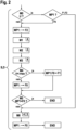
- ein das erfindungsgemäße Verfahren erläuterndes Ablaufdiagramm.
-
Figur 1 illustriert schematisch den Aufbau eines erfindungsgemäßen Systems 1. Das System 1 umfasst eine Aktuator-Steuerungseinheit 2, mittels welcher ein Aktuator 20 der inFigur 1 nicht näher dargestellten Feststellbremse zwischen verschiedenen Aktuator-Positionen verstellt werden kann. Insbesondere kann der Aktuator 20 zwischen einer Verriegelungsposition und einer Entriegelungsposition verstellt werden, wobei der Aktuator grundsätzlich auch in eine beliebige Anzahl von Zwischenpositionen zwischen der Verriegelungsposition und der Entriegelungsposition verstellt werden kann. Des Weiteren umfasst das System 1 eine beschreibbare, nicht flüchtige Speichereinheit 3. In der Speichereinheit 3 können Positionsdaten P abgelegt werden, welche die vom Aktuator 20 momentan eingenommene Aktuatorposition AP beschreiben. - Des Weiteren umfasst das System 1 eine Bremssteuerungseinrichtung 4, in welcher ein Computerprogrammprodukt ausgeführt werden kann. Eine solche Bremssteuerungseinrichtung 4 kann im vorliegenden System als so genannter "Host" fungieren, der u.a. zum Betrieb der Feststellbremse erforderliche Hardware bereitstellt. In der Bremssteuerungseinrichtung 4 ist das Computerprogrammprodukt ausführbar, mittels welchem indirekt - durch Ansteuerung der Aktuator-Steuerungseinheit 2 - der Aktuator 20 angesteuert und auf diese Weise verstellt werden kann.
- Im Zuge einer solchen Ansteuerung des Aktuators 20 können die Bremssteuerungseinrichtung 4 und die Aktuator-Steuerungseinheit 2 über eine Kommunikationsverbindung 5 miteinander datenaustauschend kommunizieren. Dies geschieht beispielsweise, wenn die Feststellbremse verriegelt und hierzu der Aktuator 20 von der Entriegelungsposition in die Verriegelungsposition verstellt werden soll. In diesem Fall fordert das in der Bremssteuerungseinrichtung 4 ausgeführte Computerprogrammprodukt über die Kommunikationsverbindung 5 von der Aktuator-Steuerungseinheit 2 eine solche Verstellung des Aktuators 20 an.
- Beim Verstellen des Aktuators 20 ändert sich kontinuierlich die momentane Aktuatorposition AP. Der Wert der sich während der Verstellung ständig ändernden momentanen Aktuatorposition AP wird als Positionsdaten P von der Aktuator-Steuerungseinheit 2 in die Speichereinheit 3 geschrieben.
- Bei herkömmlichen Systemen kann es zu Verzögerungen beim Schreibvorgang und - damit einhergehend - zu einer verzögerten Ansteuerung des Aktuators 20 kommen, da das Verstellen des Aktuators 20 nicht unabhängig vom Schreiben der momentanen Aktuatorposition AP in die Speichereinheit 3 und insbesondere nicht zeitlich parallel zu diesem Schreibvorgang erfolgt.
- Wie die Darstellung der
Figur 2 veranschaulicht, welche einen Durchlauf D des erfindungsgemäßen Verfahrens schematisch illustriert, werden beim erfindungsgemäßen Verfahren die in der Speichereinheit 3 abgelegten Positionsdaten P unabhängig vom Verstellen des Aktuators 20 synchronisiert, d.h. der Durchlauf D umfasst einen Synchronisationsvorgang S für die Positionsdaten P mit der tatsächlichen Aktuatorposition AP des Aktuators 20. Mittels eines solchen Synchronisationsvorgangs S wird sichergestellt, dass in der Speichereinheit 3 abgelegten Positionsdaten P die Aktuatorposition AP richtig wiedergeben. Dies gilt auch bzw. insbesondere, wenn es zu Verzögerungen beim Schreibvorgang oder Fehlern beim Schreibvorgang kommt, etwa, weil das Ablegen, also Speichern der Positionsdaten P in der Speichereinheit 3 neu organisiert wird. Beim erfindungsgemäßen Verfahren werden die in der Speichereinheit 3 momentan abgelegten Positionsdaten P also aktualisiert, während die Ansteuerung und somit die Verstellung des Aktuators 20 fortgesetzt wird. Insbesondere wird bei Auftreten eines Schreibfehlers beim Schreiben der Positionsdaten P in die Speichereinheit 3 die Ansteuerung des Aktuators 20 zum Verstellen durch die Aktuator-Steuerungseinheit 2 nicht unterbrochen, sondern fortgesetzt. Die Synchronisation der Positionsdaten P und die Ansteuerung bzw. Verstellung des Aktuators 20 können dabei zeitlich parallel zueinander erfolgen. - Im gezeigten Durchlauf D des Verfahrens wird gemäß dem Beispielszenario der
Figur 2 ein Markierungsparameter MP1 verwendet, welcher ebenso wie die Positionsdaten P lesbar und schreibbar, also veränderbar, in der Speichereinheit 3 abgelegt werden kann und welcher die Gültigkeit der aktuell in der Speichereinheit 3 abgelegten Positionsdaten P charakterisiert. Hierzu kann der Markierungsparameter MP1 verschiedene Werte und zwar einen Default-Wert F0 sowie zwei vom Default-Wert F0 abweichende Markierungswerte - im Folgenden als erster und zweiter Markierungswert F1 bzw. F2 bezeichnet - aufweisen. - Für den Fall, dass keinerlei Schreibfehler vorliegt oder zumindest kein Schreibfehler in die Speichereinheit 3 erkannt wurde und somit die zuletzt geschriebenen Positionsdaten P die aktuelle Aktuatorposition AP des Aktuators 20 korrekt wiedergeben, wird der Markierungsparameter MP1 im Zuge des Verfahrens auf den Default-Wert F0 gesetzt. Der erste Markierungswert F1 spiegelt demgegenüber wieder, dass beim Schreibvorgang ein Time-Out-Fehler aufgetreten ist. Da zu Beginn eines Schreibvorgangs der Markierungsparameter MP1 auf den zweiten Markierungswert F2 gesetzt und nach Abschluss des Schreibvorgangs auf den Default-Wert F0 zurückgesetzt wird, bedeutet das Vorliegen des zweiten Markierungswerts F2 zu einem anderen Zeitpunkt als während eines Schreibvorgangs, insbesondere bei Abfrage des Markierungsparameters MP1 zu Beginn des Verfahrens, dass der Schreibvorgang aufgrund einer Unterbrechung der elektrischen Stromzufuhr unterbrochen wurde.
- Im Folgenden wird nun der erwähnte Durchlauf D des erfindungsgemäßen Verfahrens anhand des Ablaufdiagramms der
Figur 2 genauer erläutert. Es versteht sich, dass das Verfahren iterativ durchgeführt werden kann, wozu mehrere Durchläufe D aneinander gereiht werden können. Es wird beispielhaft angenommen, dass als Antriebsaggregat des Kraftfahrzeugs eine Brennkraftmaschine dient. - Zu Beginn des Durchlaufs D wird gemäß einer Maßnahme M0 überprüft, ob während des vorangehenden Zündungszyklus der Brennkraftmaschine eine unerwartete Unterbrechung U der elektrischen Leistungszufuhr erfolgt ist. Trifft dies zu, so wird der Markierungsparameter MP1 abgefragt. Ergibt die Abfrage, dass dieser den Wert F0 aufweist, so werden die gespeicherten Positionsdaten P als gültig eingestuft.
- Ist der Markierungsparameter MP1 hingegen auf den ersten Markierungswert F1 gesetzt, so bedeutet dies, dass zwar keine Unterbrechung der Stromzufuhr stattgefunden hat, jedoch dennoch ein Schreibfehler in Form eines Time-Outs aufgetreten ist, und die gespeicherten Positionsdaten P werden als ungültig eingestuft. Ist der Markierungsparameter MP1 auf den zweiten Markierungswert F2 gesetzt, so bedeutet dies, dass im vorangehenden Zündungszyklus während des Schreibvorgangs der Positionsdaten P eine Unterbrechung U der elektrischen Leistungszufuhr stattgefunden hat.
- Auch in diesem Fall werden die Positionsdaten P als ungültig eingestuft.
- Ergibt voranstehende Überprüfung gemäß Maßnahme M0, dass der Markierungsparameter MP1 auf den ersten oder zweiten Markierungswert F1, F2 gesetzt ist, so wird das Verfahren mit der noch zu erläuternden Maßnahme M6 fortgesetzt, d.h. die ebenfalls noch zu erläuternden Maßnahmen M2 bis M5 werden übersprungen.
- Ergibt hingegen voranstehende Überprüfung gemäß Maßnahme M0, dass der Markierungsparameter MP1 auf den Default-Wert F0 gesetzt ist, so wird der Markierungsparameter auf den Wert F2 gesetzt, was bedeutet, dass in der Folge ein Schreibvorgang ausgeführt werden wird.
- In einer darauf folgenden Maßnahme M1 wird von der Bremssteuerungseinrichtung 4 über die Kommunikationsverbindung 5 von der Aktuator-Steuerungseinheit 2 eine Verstellbewegung des Aktuator 20, beispielsweise von der Entriegelungsposition in die Verriegelungsposition, angefordert.
- In Reaktion auf Maßnahme M1 wird in einer auf Maßnahme M1 folgenden Maßnahme M2 die Bremssteuerungseinrichtung 4 über die Kommunikationsverbindung 5 von der Aktuator-Steuerungseinheit 2 aufgefordert, die in der Speichereinheit 3 abgelegten Positionsdaten P entsprechend der sich beim Verstellen des Aktuators 20 ergebenden Veränderung der Aktuatorposition AP anzupassen, was im Zuge einer auf Maßnahme M2 folgenden Maßnahme M3 des erfindungsgemäßen Verfahrens erfolgt.
- Im Zuge einer auf Maßnahme M3 folgenden Maßnahme M4 des Verfahrens wird geprüft, ob beim Schreibvorgang der geänderten Positionsdaten P in die Speichereinheit 3 ein Fehler aufgetreten ist. Der Schreibvorgang wird dabei als fehlerhaft eingestuft, wenn eine vorbestimmte maximale Zeitdauer tmax für die Durchführung des Schreibvorgangs überschritten wurde. Ist dies der Fall, so wird der Markierungsparameter MP1 im Zuge von Maßnahme M4 vom zweiten Markierungswert F2 in den ersten Markierungswert F1 geändert, wenn beim Schreibvorgang der geänderten Positionsdaten P in die Speichereinheit 3 ein Fehler aufgetreten ist. Ist beim Schreibvorgang kein Fehler aufgetreten, so wird der Markierungsparameter MP1 im Zuge von Maßnahme M4 vom zweiten Markierungswert F2 in den Default-Wert F0 geändert
- Unabhängig davon, ob der Schreibvorgang als fehlerhaft eingestuft wird oder nicht, wird die Ansteuerung des Aktuators 20 durch die Aktuator-Steuerungseinheit 2 fortgesetzt.
- Wird kein Fehler erkannt, so wird der Markierungsparameter MP1 im Anschluss an Maßnahme M4 wieder auf den Default-Wert F0 zurückgesetzt.
- In einer weiteren Maßnahme M5 wird der Wert des Markierungsparameters MP1 abgefragt. Ergibt sich, dass dieser auf den Default-Wert F0 gesetzt ist, was bedeutet, dass der zuvor durchgeführte Schreibvorgang erfolgreich abgeschlossen werden konnte und die gespeicherten Positionsdaten P gültig sind, so wird der aktuelle Durchlauf D des Verfahrens beendet. Ist der Markierungsparameter MP1 hingegen auf den ersten Markierungswert F1 oder auf den zweiten Markierungswert MP2 gesetzt, so erfolgt gemäß einer weiteren Maßnahme M6 eine erneute Anpassung der gespeicherten Positionsdaten P an die momentane Aktuatorposition AP, so dass danach die in der Speichereinheit 3 abgelegten Positionsdaten P gültig sind und die momentane Aktuatorposition AP korrekt wiedergeben. Anschließend wird der Markierungsparameter MP1 auf den Default-Wert F0 gesetzt und das Verfahren beendet.
Claims (9)
- Steuerverfahren zum Verstellen einer elektromechanischen Feststellbremse,- gemäß welchem ein Aktuator (20) der Feststellbremse durch Ansteuerung mittels einer Aktuator-Steuerungseinheit (2) verstellt wird,- wobei eine beschreibbare, nichtflüchtige Speichereinheit (3) vorgesehen ist, in welcher Positionsdaten (P) betreffend die momentane Aktuatorposition (AP) des Aktuators (20) lesbar und schreibbar gespeichert sind;- gemäß welchem bei Auftreten eines Schreibfehlers oder beim Schreiben der Positionsdaten (P) in die Speichereinheit (3) die Ansteuerung des Aktuators (20) zum Verstellen desselben fortgesetzt wird,- gemäß welchem bei Erkennen des Schreibfehlers unabhängig von der Ansteuerung des Aktuators (20) ein Synchronisationsvorgang (S) ausgeführt wird, so dass nach Abschluss dieses Synchronisationsvorgangs (S) die in der Speichereinheit (3) abgelegten Positionsdaten (P) die Aktuatorposition (AP) des Aktuators (20) korrekt wiedergeben.
- Verfahren nach Anspruch 1,
dadurch gekennzeichnet, dass
der Synchronisationsvorgang (S) zeitlich parallel zur Ansteuerung des Aktuators (20) erfolgt. - Verfahren nach Anspruch 1 oder 2,
dadurch gekennzeichnet, dass
das Verfahren wenigstens einen die Gültigkeit der momentan in der Speichereinheit (3) abgelegten Positionsdaten (P) charakterisierenden Markierungsparameter (MP1) verwendet, der einen Default-Wert (F0) und wenigstens einen davon abweichenden Markierungs-Wert (F1, F2) annehmen kann. - Verfahren nach Anspruch 3,
dadurch gekennzeichnet, dass
der Markierungsparameter (MP1) vom Default-Wert (F0) in einen ersten Markierungswert (F1) oder zweiten Markierungswert (F2) geändert wird, wenn beim einem Schreibvorgang der Positionsdaten (P) in die Speichereinheit (3) ein Fehler aufgetreten ist. - Verfahren nach Anspruch 4,
dadurch gekennzeichnet, dass
der Schreibvorgang als fehlerhaft eingestuft und der Markierungsparameter (MP1) in den ersten Markierungswert (F1) geändert wird, wenn eine vorbestimmte maximale Zeitdauer (tmax) für die Durchführung des Schreibvorgangs überschritten wurde. - Verfahren nach Anspruch 4 oder 5,
dadurch gekennzeichnet, dass
vor Beginn des Schreibvorgangs der Markierungsparameter (MP1) in den zweiten Markierungswert (F2) geändert wird, so dass auf diese Weise eine unerwartete elektrische Unterbrechung (U) der elektrischen Leistungszufuhr an den Aktuator (20) erkannt werden kann. - Verfahren nach Anspruch 6,
dadurch gekennzeichnet, dass
nach Ende des Schreibvorgangs der Markierungsparameter (MP1) in den Default-Wert (F0) geändert wird. - Verfahren nach einem der vorhergehenden Ansprüche,
dadurch gekennzeichnet, dass
zu Beginn des Verfahrens durch Abfrage des Markierungsparameters (MP1) überprüft wird, ob in der Speichereinheit (3) gültige Positionsdaten (P) vorliegen oder nicht und, falls keine gültigen Positionsdaten (P) vorliegen, eine (erneute) Anpassung der gespeicherten Positionsdaten (P) an die momentane Aktuatorposition (AP) erfolgt. - System (1),- mit einem steuerbaren Aktuator (20) für eine elektromechanische Feststellbremse, der zwischen einer Verriegelungsposition und einer Entriegelungsposition verstellbar ist;- mit einer Aktuator-Steuerungseinheit (2) zum Steuern des Aktuators (20);- mit einer Bremssteuerungseinrichtung (4) zum Ausführen eines Computerprogrammprodukts, die mittels einer Kommunikationsverbindung (5) mit der Aktuator-Steuerungseinheit (2) kommuniziert;- dadurch gekennzeichnet, dass das System (1) zur Durchführung des Verfahrens nach einem der vorhergehenden Ansprüche eingerichtet/programmiert ist.
Applications Claiming Priority (2)
| Application Number | Priority Date | Filing Date | Title |
|---|---|---|---|
| DE102020214600.4A DE102020214600A1 (de) | 2020-11-19 | 2020-11-19 | Steuerverfahren zum Verstellen einer elektromechanischen Feststellbremse |
| PCT/EP2021/080444 WO2022106195A1 (de) | 2020-11-19 | 2021-11-03 | Steuerverfahren zum verstellen einer elektromechanischen feststellbremse |
Publications (2)
| Publication Number | Publication Date |
|---|---|
| EP4247685A1 EP4247685A1 (de) | 2023-09-27 |
| EP4247685B1 true EP4247685B1 (de) | 2024-10-09 |
Family
ID=78592848
Family Applications (1)
| Application Number | Title | Priority Date | Filing Date |
|---|---|---|---|
| EP21805920.2A Active EP4247685B1 (de) | 2020-11-19 | 2021-11-03 | Steuerverfahren zum verstellen einer elektromechanischen feststellbremse |
Country Status (6)
| Country | Link |
|---|---|
| US (1) | US12447941B2 (de) |
| EP (1) | EP4247685B1 (de) |
| JP (1) | JP7636542B2 (de) |
| CN (1) | CN116583447B (de) |
| DE (1) | DE102020214600A1 (de) |
| WO (1) | WO2022106195A1 (de) |
Family Cites Families (11)
| Publication number | Priority date | Publication date | Assignee | Title |
|---|---|---|---|---|
| US5335174A (en) * | 1990-04-04 | 1994-08-02 | Zexel Corporation | Correcting method for data used for control operation of vehicular clutch |
| DE102004060454A1 (de) * | 2003-11-27 | 2006-06-29 | Küster Automotive Control Systems GmbH | Verfahren und Vorrichtung zum Betätigen einer Feststellbremsanlage für Fahrzeuge, insbesondere Personen- und Lastkraftwagen |
| DE10355997B3 (de) * | 2003-11-27 | 2005-01-13 | Küster Automotive Control Systems GmbH | Verfahren und Vorrichtung zum Feststellen und Lösen einer Feststellbremsanlage für Fahrzeuge |
| JP4466582B2 (ja) | 2006-02-17 | 2010-05-26 | トヨタ自動車株式会社 | 電動パーキングブレーキ装置 |
| DE102010038306A1 (de) * | 2010-06-15 | 2011-12-15 | Continental Teves Ag & Co. Ohg | Verfahren und Vorrichtung zur Regelung einer elektrisch betätigbaren Bremse sowie elektronisches Bremssystem |
| DE102010041099A1 (de) | 2010-09-21 | 2012-03-22 | Robert Bosch Gmbh | Feststellbremse mit automatischer Rekalibrierung nach einem Steuergeräteausfall |
| DE102011004763A1 (de) | 2011-02-25 | 2012-08-30 | Robert Bosch Gmbh | Verfahren zum Betätigen einer Feststellbremse in einem Fahrzeug |
| JP6313152B2 (ja) | 2014-07-18 | 2018-04-18 | Ntn株式会社 | 電動ブレーキ装置 |
| DE102016010823A1 (de) * | 2016-09-08 | 2018-03-08 | Lucas Automotive Gmbh | Technik zum Ermitteln der Lage eines Abstützpunktes einer Feststellbremseinheit |
| US10516683B2 (en) | 2017-02-15 | 2019-12-24 | Ford Global Technologies, Llc | Systems and methods for security breach detection in vehicle communication systems |
| JP2019130938A (ja) | 2018-01-29 | 2019-08-08 | 日立オートモティブシステムズ株式会社 | 電動ブレーキ装置および電動ブレーキ制御装置 |
-
2020
- 2020-11-19 DE DE102020214600.4A patent/DE102020214600A1/de active Pending
-
2021
- 2021-11-03 CN CN202180077738.6A patent/CN116583447B/zh active Active
- 2021-11-03 JP JP2023528938A patent/JP7636542B2/ja active Active
- 2021-11-03 EP EP21805920.2A patent/EP4247685B1/de active Active
- 2021-11-03 WO PCT/EP2021/080444 patent/WO2022106195A1/de not_active Ceased
- 2021-11-03 US US18/249,002 patent/US12447941B2/en active Active
Also Published As
| Publication number | Publication date |
|---|---|
| WO2022106195A1 (de) | 2022-05-27 |
| DE102020214600A1 (de) | 2022-05-19 |
| JP2023549410A (ja) | 2023-11-24 |
| CN116583447A (zh) | 2023-08-11 |
| US12447941B2 (en) | 2025-10-21 |
| EP4247685A1 (de) | 2023-09-27 |
| JP7636542B2 (ja) | 2025-02-26 |
| CN116583447B (zh) | 2025-12-23 |
| US20230322196A1 (en) | 2023-10-12 |
Similar Documents
| Publication | Publication Date | Title |
|---|---|---|
| DE102012211901B4 (de) | Verfahren zur Spurhalteunterstützung für Kraftfahrzeuge | |
| EP1967435B1 (de) | Verfahren zur adaptiven konfigurationserkennung | |
| EP3694759B1 (de) | Kontrollsystem für ein kraftfahrzeug, kraftfahrzeug, verfahren zur kontrolle eines kraftfahrzeugs, computerprogrammprodukt und computerlesbares medium | |
| EP4114696B1 (de) | Bremsanlage mit redundanter parkbremsenansteuerung | |
| DE102016219409B4 (de) | Elektromechanische Bremse, welche in der Lage ist, eine Änderung hinsichtlich Motoreigenschaften zu erkennen | |
| WO2007082743A1 (de) | Verfahren zum anzeigen von verschleiss zumindest eines bremsbelags bei einer scheibenbremse mit elektromotorischem aktuator | |
| WO2009059854A1 (de) | Verfahren und vorrichtung zur durchführung sowohl einer adaption wie einer diagnose bei emissionsrelevanten steuereinrichtungen in einem fahrzeug | |
| WO2008006613A1 (de) | Verfahren zum synchronisieren von komponenten eines kraftfahrzeugbremssystems und elektronisches bremssteuersystem | |
| WO2018082846A1 (de) | Verfahren zum zuordnen von reifen-sensor-modulen zu einem anhängerfahrzeug eines eigenen nutzfahrzeug-gespanns | |
| DE102020200494A1 (de) | Bremssystem, Mehrzahl von Steuergeräten für ein Bremssystem, sowie Verfahren zum Betreiben eines Bremssystems | |
| DE10324808A1 (de) | Optimierte Steuergerät-Konfiguration für eine Kfz-Feststellbremse | |
| EP4247685B1 (de) | Steuerverfahren zum verstellen einer elektromechanischen feststellbremse | |
| DE102008039564B4 (de) | Verfahren zum Abarbeiten von Aufgaben und System mit einem ersten und einem zweiten Steuergerät | |
| WO2019224017A1 (de) | Kontrollsystem für ein kraftfahrzeug, kraftfahrzeug, verfahren zur kontrolle eines kraftfahrzeugs, computerprogrammprodukt und computerlesbares medium | |
| EP3737589B1 (de) | Verfahren zum herstellen eines steuersystems für ein kraftfahrzeug, steuersystem | |
| DE112016006679B4 (de) | Steuerungsvorrichtung und Recovery-Verarbeitungsverfahren für Steuerungsvorrichtung | |
| EP1395885A2 (de) | Verfahren zum betrieb einer positionsmesseinrichtung | |
| EP3797352A1 (de) | Verfahren zum austauschen eines ersten ausführbaren programm-codes und eines zweiten ausführbaren programm-codes und steuergerät | |
| WO2004086157A1 (de) | Verfahren zum vermeiden von fehlerhaften aktuatorzugriffen in einem multifunktionalen elektronischen gesamtregelungssystem | |
| DE102006044422A1 (de) | Verfahren zum Betätigen einer elektromechanischen Parkbremse eines Fahrzeugs | |
| DE102021207244A1 (de) | Steuervorrichtung für zumindest eine erste Komponente eines Systems und Ansteuervorrichtung für zumindest eine zweite Komponente des gleichen Systems zum Zusammenwirken mit der Steuervorrichtung | |
| EP1528996B1 (de) | Verfahren und vorrichtung zur bereitstellung von betriebsdaten von funktionskomponenten eines kraftfahrzeugbremsensteuergeräts | |
| EP1477905B1 (de) | Projektierungsverfahren und Diagnoseverfahren für ein Automatisierungssystem | |
| WO2005113305A1 (de) | Feststellbremsanlage mit verbesserter steuerung | |
| WO2020011678A1 (de) | Verfahren zum zurücksetzen eines fahrzeugs, verfahren zum betreiben eines fahrzeugs und system für ein fahrzeug |
Legal Events
| Date | Code | Title | Description |
|---|---|---|---|
| STAA | Information on the status of an ep patent application or granted ep patent |
Free format text: STATUS: UNKNOWN |
|
| STAA | Information on the status of an ep patent application or granted ep patent |
Free format text: STATUS: THE INTERNATIONAL PUBLICATION HAS BEEN MADE |
|
| PUAI | Public reference made under article 153(3) epc to a published international application that has entered the european phase |
Free format text: ORIGINAL CODE: 0009012 |
|
| STAA | Information on the status of an ep patent application or granted ep patent |
Free format text: STATUS: REQUEST FOR EXAMINATION WAS MADE |
|
| 17P | Request for examination filed |
Effective date: 20230619 |
|
| AK | Designated contracting states |
Kind code of ref document: A1 Designated state(s): AL AT BE BG CH CY CZ DE DK EE ES FI FR GB GR HR HU IE IS IT LI LT LU LV MC MK MT NL NO PL PT RO RS SE SI SK SM TR |
|
| DAV | Request for validation of the european patent (deleted) | ||
| DAX | Request for extension of the european patent (deleted) | ||
| GRAP | Despatch of communication of intention to grant a patent |
Free format text: ORIGINAL CODE: EPIDOSNIGR1 |
|
| STAA | Information on the status of an ep patent application or granted ep patent |
Free format text: STATUS: GRANT OF PATENT IS INTENDED |
|
| INTG | Intention to grant announced |
Effective date: 20240715 |
|
| GRAS | Grant fee paid |
Free format text: ORIGINAL CODE: EPIDOSNIGR3 |
|
| GRAA | (expected) grant |
Free format text: ORIGINAL CODE: 0009210 |
|
| STAA | Information on the status of an ep patent application or granted ep patent |
Free format text: STATUS: THE PATENT HAS BEEN GRANTED |
|
| AK | Designated contracting states |
Kind code of ref document: B1 Designated state(s): AL AT BE BG CH CY CZ DE DK EE ES FI FR GB GR HR HU IE IS IT LI LT LU LV MC MK MT NL NO PL PT RO RS SE SI SK SM TR |
|
| REG | Reference to a national code |
Ref country code: CH Ref legal event code: EP |
|
| REG | Reference to a national code |
Ref country code: DE Ref legal event code: R096 Ref document number: 502021005462 Country of ref document: DE |
|
| REG | Reference to a national code |
Ref country code: IE Ref legal event code: FG4D Free format text: LANGUAGE OF EP DOCUMENT: GERMAN |
|
| REG | Reference to a national code |
Ref country code: LT Ref legal event code: MG9D |
|
| REG | Reference to a national code |
Ref country code: NL Ref legal event code: MP Effective date: 20241009 |
|
| PG25 | Lapsed in a contracting state [announced via postgrant information from national office to epo] |
Ref country code: NL Free format text: LAPSE BECAUSE OF FAILURE TO SUBMIT A TRANSLATION OF THE DESCRIPTION OR TO PAY THE FEE WITHIN THE PRESCRIBED TIME-LIMIT Effective date: 20241009 |
|
| PG25 | Lapsed in a contracting state [announced via postgrant information from national office to epo] |
Ref country code: NL Free format text: LAPSE BECAUSE OF FAILURE TO SUBMIT A TRANSLATION OF THE DESCRIPTION OR TO PAY THE FEE WITHIN THE PRESCRIBED TIME-LIMIT Effective date: 20241009 |
|
| PG25 | Lapsed in a contracting state [announced via postgrant information from national office to epo] |
Ref country code: HR Free format text: LAPSE BECAUSE OF FAILURE TO SUBMIT A TRANSLATION OF THE DESCRIPTION OR TO PAY THE FEE WITHIN THE PRESCRIBED TIME-LIMIT Effective date: 20241009 Ref country code: PT Free format text: LAPSE BECAUSE OF FAILURE TO SUBMIT A TRANSLATION OF THE DESCRIPTION OR TO PAY THE FEE WITHIN THE PRESCRIBED TIME-LIMIT Effective date: 20250210 Ref country code: IS Free format text: LAPSE BECAUSE OF FAILURE TO SUBMIT A TRANSLATION OF THE DESCRIPTION OR TO PAY THE FEE WITHIN THE PRESCRIBED TIME-LIMIT Effective date: 20250209 |
|
| PG25 | Lapsed in a contracting state [announced via postgrant information from national office to epo] |
Ref country code: FI Free format text: LAPSE BECAUSE OF FAILURE TO SUBMIT A TRANSLATION OF THE DESCRIPTION OR TO PAY THE FEE WITHIN THE PRESCRIBED TIME-LIMIT Effective date: 20241009 |
|
| PG25 | Lapsed in a contracting state [announced via postgrant information from national office to epo] |
Ref country code: BG Free format text: LAPSE BECAUSE OF FAILURE TO SUBMIT A TRANSLATION OF THE DESCRIPTION OR TO PAY THE FEE WITHIN THE PRESCRIBED TIME-LIMIT Effective date: 20241009 |
|
| PG25 | Lapsed in a contracting state [announced via postgrant information from national office to epo] |
Ref country code: ES Free format text: LAPSE BECAUSE OF FAILURE TO SUBMIT A TRANSLATION OF THE DESCRIPTION OR TO PAY THE FEE WITHIN THE PRESCRIBED TIME-LIMIT Effective date: 20241009 |
|
| PG25 | Lapsed in a contracting state [announced via postgrant information from national office to epo] |
Ref country code: NO Free format text: LAPSE BECAUSE OF FAILURE TO SUBMIT A TRANSLATION OF THE DESCRIPTION OR TO PAY THE FEE WITHIN THE PRESCRIBED TIME-LIMIT Effective date: 20250109 |
|
| PG25 | Lapsed in a contracting state [announced via postgrant information from national office to epo] |
Ref country code: LV Free format text: LAPSE BECAUSE OF FAILURE TO SUBMIT A TRANSLATION OF THE DESCRIPTION OR TO PAY THE FEE WITHIN THE PRESCRIBED TIME-LIMIT Effective date: 20241009 Ref country code: GR Free format text: LAPSE BECAUSE OF FAILURE TO SUBMIT A TRANSLATION OF THE DESCRIPTION OR TO PAY THE FEE WITHIN THE PRESCRIBED TIME-LIMIT Effective date: 20250110 |
|
| PG25 | Lapsed in a contracting state [announced via postgrant information from national office to epo] |
Ref country code: PL Free format text: LAPSE BECAUSE OF FAILURE TO SUBMIT A TRANSLATION OF THE DESCRIPTION OR TO PAY THE FEE WITHIN THE PRESCRIBED TIME-LIMIT Effective date: 20241009 |
|
| PG25 | Lapsed in a contracting state [announced via postgrant information from national office to epo] |
Ref country code: RS Free format text: LAPSE BECAUSE OF FAILURE TO SUBMIT A TRANSLATION OF THE DESCRIPTION OR TO PAY THE FEE WITHIN THE PRESCRIBED TIME-LIMIT Effective date: 20250109 |
|
| REG | Reference to a national code |
Ref country code: CH Ref legal event code: PL |
|
| PG25 | Lapsed in a contracting state [announced via postgrant information from national office to epo] |
Ref country code: SM Free format text: LAPSE BECAUSE OF FAILURE TO SUBMIT A TRANSLATION OF THE DESCRIPTION OR TO PAY THE FEE WITHIN THE PRESCRIBED TIME-LIMIT Effective date: 20241009 |
|
| PG25 | Lapsed in a contracting state [announced via postgrant information from national office to epo] |
Ref country code: MC Free format text: LAPSE BECAUSE OF FAILURE TO SUBMIT A TRANSLATION OF THE DESCRIPTION OR TO PAY THE FEE WITHIN THE PRESCRIBED TIME-LIMIT Effective date: 20241009 |
|
| PG25 | Lapsed in a contracting state [announced via postgrant information from national office to epo] |
Ref country code: DK Free format text: LAPSE BECAUSE OF FAILURE TO SUBMIT A TRANSLATION OF THE DESCRIPTION OR TO PAY THE FEE WITHIN THE PRESCRIBED TIME-LIMIT Effective date: 20241009 |
|
| REG | Reference to a national code |
Ref country code: DE Ref legal event code: R097 Ref document number: 502021005462 Country of ref document: DE |
|
| PG25 | Lapsed in a contracting state [announced via postgrant information from national office to epo] |
Ref country code: LU Free format text: LAPSE BECAUSE OF NON-PAYMENT OF DUE FEES Effective date: 20241103 |
|
| REG | Reference to a national code |
Ref country code: CH Ref legal event code: PL |
|
| PG25 | Lapsed in a contracting state [announced via postgrant information from national office to epo] |
Ref country code: EE Free format text: LAPSE BECAUSE OF FAILURE TO SUBMIT A TRANSLATION OF THE DESCRIPTION OR TO PAY THE FEE WITHIN THE PRESCRIBED TIME-LIMIT Effective date: 20241009 |
|
| PG25 | Lapsed in a contracting state [announced via postgrant information from national office to epo] |
Ref country code: CH Free format text: LAPSE BECAUSE OF NON-PAYMENT OF DUE FEES Effective date: 20241130 |
|
| PG25 | Lapsed in a contracting state [announced via postgrant information from national office to epo] |
Ref country code: RO Free format text: LAPSE BECAUSE OF FAILURE TO SUBMIT A TRANSLATION OF THE DESCRIPTION OR TO PAY THE FEE WITHIN THE PRESCRIBED TIME-LIMIT Effective date: 20241009 |
|
| PG25 | Lapsed in a contracting state [announced via postgrant information from national office to epo] |
Ref country code: SK Free format text: LAPSE BECAUSE OF FAILURE TO SUBMIT A TRANSLATION OF THE DESCRIPTION OR TO PAY THE FEE WITHIN THE PRESCRIBED TIME-LIMIT Effective date: 20241009 |
|
| PG25 | Lapsed in a contracting state [announced via postgrant information from national office to epo] |
Ref country code: CZ Free format text: LAPSE BECAUSE OF FAILURE TO SUBMIT A TRANSLATION OF THE DESCRIPTION OR TO PAY THE FEE WITHIN THE PRESCRIBED TIME-LIMIT Effective date: 20241009 |
|
| PG25 | Lapsed in a contracting state [announced via postgrant information from national office to epo] |
Ref country code: IT Free format text: LAPSE BECAUSE OF FAILURE TO SUBMIT A TRANSLATION OF THE DESCRIPTION OR TO PAY THE FEE WITHIN THE PRESCRIBED TIME-LIMIT Effective date: 20241009 |
|
| PLBE | No opposition filed within time limit |
Free format text: ORIGINAL CODE: 0009261 |
|
| STAA | Information on the status of an ep patent application or granted ep patent |
Free format text: STATUS: NO OPPOSITION FILED WITHIN TIME LIMIT |
|
| REG | Reference to a national code |
Ref country code: BE Ref legal event code: MM Effective date: 20241130 |
|
| PG25 | Lapsed in a contracting state [announced via postgrant information from national office to epo] |
Ref country code: SE Free format text: LAPSE BECAUSE OF FAILURE TO SUBMIT A TRANSLATION OF THE DESCRIPTION OR TO PAY THE FEE WITHIN THE PRESCRIBED TIME-LIMIT Effective date: 20241009 |
|
| 26N | No opposition filed |
Effective date: 20250710 |
|
| PG25 | Lapsed in a contracting state [announced via postgrant information from national office to epo] |
Ref country code: BE Free format text: LAPSE BECAUSE OF NON-PAYMENT OF DUE FEES Effective date: 20241130 |
|
| PG25 | Lapsed in a contracting state [announced via postgrant information from national office to epo] |
Ref country code: IE Free format text: LAPSE BECAUSE OF NON-PAYMENT OF DUE FEES Effective date: 20241103 |
|
| PGFP | Annual fee paid to national office [announced via postgrant information from national office to epo] |
Ref country code: GB Payment date: 20251120 Year of fee payment: 5 |
|
| PGFP | Annual fee paid to national office [announced via postgrant information from national office to epo] |
Ref country code: AT Payment date: 20260113 Year of fee payment: 5 |
|
| PGFP | Annual fee paid to national office [announced via postgrant information from national office to epo] |
Ref country code: FR Payment date: 20251125 Year of fee payment: 5 |
|
| PG25 | Lapsed in a contracting state [announced via postgrant information from national office to epo] |
Ref country code: HU Free format text: LAPSE BECAUSE OF FAILURE TO SUBMIT A TRANSLATION OF THE DESCRIPTION OR TO PAY THE FEE WITHIN THE PRESCRIBED TIME-LIMIT; INVALID AB INITIO Effective date: 20211103 |
|
| PG25 | Lapsed in a contracting state [announced via postgrant information from national office to epo] |
Ref country code: CY Free format text: LAPSE BECAUSE OF FAILURE TO SUBMIT A TRANSLATION OF THE DESCRIPTION OR TO PAY THE FEE WITHIN THE PRESCRIBED TIME-LIMIT; INVALID AB INITIO Effective date: 20211103 |
|
| PGFP | Annual fee paid to national office [announced via postgrant information from national office to epo] |
Ref country code: DE Payment date: 20260126 Year of fee payment: 5 |