EP4246864A2 - Dämpfungsmusterkonfigurationsoptionen für downlink-positionierungsreferenzsignale (prs) - Google Patents
Dämpfungsmusterkonfigurationsoptionen für downlink-positionierungsreferenzsignale (prs) Download PDFInfo
- Publication number
- EP4246864A2 EP4246864A2 EP23189339.7A EP23189339A EP4246864A2 EP 4246864 A2 EP4246864 A2 EP 4246864A2 EP 23189339 A EP23189339 A EP 23189339A EP 4246864 A2 EP4246864 A2 EP 4246864A2
- Authority
- EP
- European Patent Office
- Prior art keywords
- prs
- resources
- subgroup
- prs resources
- repetitions
- Prior art date
- Legal status (The legal status is an assumption and is not a legal conclusion. Google has not performed a legal analysis and makes no representation as to the accuracy of the status listed.)
- Pending
Links
- 230000005540 biological transmission Effects 0.000 claims abstract description 106
- 238000000034 method Methods 0.000 claims abstract description 86
- 238000004891 communication Methods 0.000 claims abstract description 57
- 125000004122 cyclic group Chemical group 0.000 claims description 20
- 238000005259 measurement Methods 0.000 claims description 12
- 230000006870 function Effects 0.000 description 55
- 238000012545 processing Methods 0.000 description 45
- 239000002609 medium Substances 0.000 description 19
- 238000007726 management method Methods 0.000 description 14
- 230000032258 transport Effects 0.000 description 13
- 239000000969 carrier Substances 0.000 description 11
- 238000001228 spectrum Methods 0.000 description 11
- 238000005516 engineering process Methods 0.000 description 10
- 230000011664 signaling Effects 0.000 description 8
- 230000001413 cellular effect Effects 0.000 description 7
- 238000010586 diagram Methods 0.000 description 6
- 230000009471 action Effects 0.000 description 5
- 238000012937 correction Methods 0.000 description 5
- 238000001514 detection method Methods 0.000 description 5
- 238000013507 mapping Methods 0.000 description 5
- 238000012546 transfer Methods 0.000 description 5
- 230000006837 decompression Effects 0.000 description 4
- 230000033001 locomotion Effects 0.000 description 4
- 230000003287 optical effect Effects 0.000 description 4
- 239000002245 particle Substances 0.000 description 4
- 230000002441 reversible effect Effects 0.000 description 4
- 230000008901 benefit Effects 0.000 description 3
- 238000004422 calculation algorithm Methods 0.000 description 3
- 230000006835 compression Effects 0.000 description 3
- 238000007906 compression Methods 0.000 description 3
- 238000013461 design Methods 0.000 description 3
- 238000012795 verification Methods 0.000 description 3
- 230000008859 change Effects 0.000 description 2
- 239000000835 fiber Substances 0.000 description 2
- 230000007246 mechanism Effects 0.000 description 2
- 238000010295 mobile communication Methods 0.000 description 2
- 238000012986 modification Methods 0.000 description 2
- 230000004048 modification Effects 0.000 description 2
- 230000000737 periodic effect Effects 0.000 description 2
- 230000010363 phase shift Effects 0.000 description 2
- 238000012913 prioritisation Methods 0.000 description 2
- 230000005855 radiation Effects 0.000 description 2
- 238000013468 resource allocation Methods 0.000 description 2
- 230000011218 segmentation Effects 0.000 description 2
- 241000700159 Rattus Species 0.000 description 1
- 230000002776 aggregation Effects 0.000 description 1
- 238000004220 aggregation Methods 0.000 description 1
- 238000003491 array Methods 0.000 description 1
- 230000003190 augmentative effect Effects 0.000 description 1
- 238000013475 authorization Methods 0.000 description 1
- 230000003139 buffering effect Effects 0.000 description 1
- 238000004364 calculation method Methods 0.000 description 1
- 238000004590 computer program Methods 0.000 description 1
- 230000003247 decreasing effect Effects 0.000 description 1
- 230000001419 dependent effect Effects 0.000 description 1
- 230000009977 dual effect Effects 0.000 description 1
- 239000011521 glass Substances 0.000 description 1
- 230000006872 improvement Effects 0.000 description 1
- 238000007689 inspection Methods 0.000 description 1
- 230000007774 longterm Effects 0.000 description 1
- 239000000463 material Substances 0.000 description 1
- 238000005192 partition Methods 0.000 description 1
- 230000008569 process Effects 0.000 description 1
- 230000001105 regulatory effect Effects 0.000 description 1
- 230000008054 signal transmission Effects 0.000 description 1
- 230000009131 signaling function Effects 0.000 description 1
- 230000003595 spectral effect Effects 0.000 description 1
- 230000001360 synchronised effect Effects 0.000 description 1
- 239000006163 transport media Substances 0.000 description 1
- 238000012384 transportation and delivery Methods 0.000 description 1
- 230000000007 visual effect Effects 0.000 description 1
Images


Classifications
-
- H—ELECTRICITY
- H04—ELECTRIC COMMUNICATION TECHNIQUE
- H04W—WIRELESS COMMUNICATION NETWORKS
- H04W72/00—Local resource management
- H04W72/50—Allocation or scheduling criteria for wireless resources
- H04W72/51—Allocation or scheduling criteria for wireless resources based on terminal or device properties
-
- H—ELECTRICITY
- H04—ELECTRIC COMMUNICATION TECHNIQUE
- H04L—TRANSMISSION OF DIGITAL INFORMATION, e.g. TELEGRAPHIC COMMUNICATION
- H04L5/00—Arrangements affording multiple use of the transmission path
- H04L5/003—Arrangements for allocating sub-channels of the transmission path
- H04L5/0048—Allocation of pilot signals, i.e. of signals known to the receiver
- H04L5/0051—Allocation of pilot signals, i.e. of signals known to the receiver of dedicated pilots, i.e. pilots destined for a single user or terminal
-
- H—ELECTRICITY
- H04—ELECTRIC COMMUNICATION TECHNIQUE
- H04W—WIRELESS COMMUNICATION NETWORKS
- H04W72/00—Local resource management
- H04W72/04—Wireless resource allocation
- H04W72/044—Wireless resource allocation based on the type of the allocated resource
- H04W72/0446—Resources in time domain, e.g. slots or frames
-
- H—ELECTRICITY
- H04—ELECTRIC COMMUNICATION TECHNIQUE
- H04W—WIRELESS COMMUNICATION NETWORKS
- H04W72/00—Local resource management
- H04W72/50—Allocation or scheduling criteria for wireless resources
- H04W72/54—Allocation or scheduling criteria for wireless resources based on quality criteria
- H04W72/542—Allocation or scheduling criteria for wireless resources based on quality criteria using measured or perceived quality
-
- H—ELECTRICITY
- H04—ELECTRIC COMMUNICATION TECHNIQUE
- H04W—WIRELESS COMMUNICATION NETWORKS
- H04W72/00—Local resource management
- H04W72/20—Control channels or signalling for resource management
- H04W72/23—Control channels or signalling for resource management in the downlink direction of a wireless link, i.e. towards a terminal
Definitions
- aspects of the disclosure relate generally to wireless communications and the like.
- Wireless communication systems have developed through various generations, including a first-generation analog wireless phone service (1G), a second-generation (2G) digital wireless phone service (including interim 2.5G networks), a third-generation (3G) high speed data, Internet-capable wireless service, and a fourth-generation (4G) service (e.g., Long-Term Evolution (LTE), WiMax).
- a first-generation analog wireless phone service (1G) 1G
- a second-generation (2G) digital wireless phone service including interim 2.5G networks
- 3G third-generation
- 3G high speed data
- Internet-capable wireless service Internet-capable wireless service
- 4G fourth-generation
- 4G fourth-generation
- LTE Long-Term Evolution
- PCS personal communications service
- Examples of known cellular systems include the cellular Analog Advanced Mobile Phone System (AMPS), and digital cellular systems based on code division multiple access (CDMA), frequency division multiple access (FDMA), time division multiple access (TDMA), the Global System for Mobile communication (GSM), etc.
- CDMA code division multiple access
- a fifth generation (5G) mobile standard calls for higher data transfer speeds, greater numbers of connections, and better coverage, among other improvements.
- the 5G standard also referred to as "New Radio” or “NR”
- NR Next Generation Mobile Networks Alliance
- NR Next Generation Mobile Networks Alliance
- 5G mobile communications should be significantly enhanced compared to the current 4G / LTE standard.
- signaling efficiencies should be enhanced and latency should be substantially reduced compared to current standards.
- a method of wireless communication performed by a user equipment includes receiving, from a transmission point, a first positioning reference signal (PRS) muting pattern for a first subgroup of PRS resources of a first PRS resource set, wherein the first PRS muting pattern comprises a plurality of N bits representing a plurality of N PRS occasions of the first subgroup of PRS resources, wherein each bit of the plurality of N bits represents a corresponding PRS occasion of the plurality of N PRS occasions of each PRS resource of the first subgroup of PRS resources, and wherein the plurality of N PRS occasions comprises a plurality of active PRS occasions of the first subgroup of PRS resources, and measuring, during at least one of the plurality of active PRS occasions of the first subgroup of PRS resources, PRS received from the transmission point.
- PRS positioning reference signal
- a method of wireless communication performed by a transmission point includes transmitting, to a UE, a first PRS muting pattern for a first subgroup of PRS resources of a first PRS resource set, wherein the first PRS muting pattern comprises a plurality of N bits representing a plurality of N PRS occasions of the first subgroup of PRS resources, wherein each bit of the plurality of N bits represents a corresponding PRS occasion of the plurality of N PRS occasions of each PRS resource of the first subgroup of PRS resources, and wherein the plurality of N PRS occasions comprises a plurality of active PRS occasions of the first subgroup of PRS resources, and transmitting PRS to the UE during at least one of the plurality of active PRS occasions of the first subgroup of PRS resources.
- a LTE includes a memory, at least one transceiver, and at least one processor communicatively coupled to the memory and the at least one transceiver, the at least one processor configured to: receive, from a transmission point via the at least one transceiver, a first PRS muting pattern for a first subgroup of PRS resources of a first PRS resource set, wherein the first PRS muting pattern comprises a plurality of N bits representing a plurality of N PRS occasions of the first subgroup of PRS resources, wherein each bit of the plurality of N bits represents a corresponding PRS occasion of the plurality of N PRS occasions of each PRS resource of the first subgroup of PRS resources, and wherein the plurality of N PRS occasions comprises a plurality of active PRS occasions of the first subgroup of PRS resources, and measure, during at least one of the plurality of active PRS occasions of the first subgroup of PRS resources, PRS received from the transmission point.
- a transmission point includes a memory, at least one transceiver, and at least one processor communicatively coupled to the memory and the at least one transceiver, the at least one processor configured to: cause the at least one transceiver to transmit, to a LTE, a first PRS muting pattern for a first subgroup of PRS resources of a first PRS resource set, wherein the first PRS muting pattern comprises a plurality of N bits representing a plurality of N PRS occasions of the first subgroup of PRS resources, wherein each bit of the plurality of N bits represents a corresponding PRS occasion of the plurality of N PRS occasions of each PRS resource of the first subgroup of PRS resources, and wherein the plurality of N PRS occasions comprises a plurality of active PRS occasions of the first subgroup of PRS resources, and cause the at least one transceiver to transmit PRS to the UE during at least one of the plurality of active PRS occasions of the first subgroup of PRS resources.
- a LTE includes means for receiving, from a transmission point, a first PRS muting pattern for a first subgroup of PRS resources of a first PRS resource set, wherein the first PRS muting pattern comprises a plurality of N bits representing a plurality of N PRS occasions of the first subgroup of PRS resources, wherein each bit of the plurality of N bits represents a corresponding PRS occasion of the plurality of N PRS occasions of each PRS resource of the first subgroup of PRS resources, and wherein the plurality of N PRS occasions comprises a plurality of active PRS occasions of the first subgroup of PRS resources, and means for measuring, during at least one of the plurality of active PRS occasions of the first subgroup of PRS resources, PRS received from the transmission point.
- a transmission point includes means for transmitting, to a LTE, a first PRS muting pattern for a first subgroup of PRS resources of a first PRS resource set, wherein the first PRS muting pattern comprises a plurality of N bits representing a plurality of N PRS occasions of the first subgroup of PRS resources, wherein each bit of the plurality of N bits represents a corresponding PRS occasion of the plurality of N PRS occasions of each PRS resource of the first subgroup of PRS resources, and wherein the plurality of N PRS occasions comprises a plurality of active PRS occasions of the first subgroup of PRS resources, and means for transmitting PRS to the UE during at least one of the plurality of active PRS occasions of the first subgroup of PRS resources.
- a non-transitory computer-readable medium storing computer-executable instructions includes computer-executable instructions comprising at least one instruction instructing a LTE to receive, from a transmission point, a first PRS muting pattern for a first subgroup of PRS resources of a first PRS resource set, wherein the first PRS muting pattern comprises a plurality of N bits representing a plurality of N PRS occasions of the first subgroup of PRS resources, wherein each bit of the plurality of N bits represents a corresponding PRS occasion of the plurality of N PRS occasions of each PRS resource of the first subgroup of PRS resources, and wherein the plurality of N PRS occasions comprises a plurality of active PRS occasions of the first subgroup of PRS resources, and at least one instruction instructing the UE to measure, during at least one of the plurality of active PRS occasions of the first subgroup of PRS resources, PRS received from the transmission point.
- a non-transitory computer-readable medium storing computer-executable instructions includes computer-executable instructions comprising at least one instruction instructing a transmission point to send, to a LTE, a first PRS muting pattern for a first subgroup of PRS resources of a first PRS resource set, wherein the first PRS muting pattern comprises a plurality of N bits representing a plurality of N PRS occasions of the first subgroup of PRS resources, wherein each bit of the plurality of N bits represents a corresponding PRS occasion of the plurality of N PRS occasions of each PRS resource of the first subgroup of PRS resources, and wherein the plurality of N PRS occasions comprises a plurality of active PRS occasions of the first subgroup of PRS resources, and at least one instruction instructing the transmission point to transmit PRS to the UE during at least one of the plurality of active PRS occasions of the first subgroup of PRS resources.
- sequences of actions to be performed by, for example, elements of a computing device. It will be recognized that various actions described herein can be performed by specific circuits (e.g., application specific integrated circuits (ASICs)), by program instructions being executed by one or more processors, or by a combination of both. Additionally, the sequence(s) of actions described herein can be considered to be embodied entirely within any form of non-transitory computer-readable storage medium having stored therein a corresponding set of computer instructions that, upon execution, would cause or instruct an associated processor of a device to perform the functionality described herein.
- ASICs application specific integrated circuits
- a UE may be any wireless communication device (e.g., a mobile phone, router, tablet computer, laptop computer, tracking device, wearable (e.g., smartwatch, glasses, augmented reality (AR) / virtual reality (VR) headset, etc.), vehicle (e.g., automobile, motorcycle, bicycle, etc.), Internet of Things (IoT) device, etc.) used by a user to communicate over a wireless communications network.
- a UE may be mobile or may (e.g., at certain times) be stationary, and may communicate with a radio access network (RAN).
- RAN radio access network
- UE may be referred to interchangeably as an "access terminal” or “AT,” a “client device,” a “wireless device,” a “subscriber device,” a “subscriber terminal,” a “subscriber station,” a “user terminal” or UT, a “mobile device,” a “mobile terminal,” a “mobile station,” or variations thereof.
- AT access terminal
- client device a “wireless device”
- subscriber device a “subscriber terminal”
- subscriber station a “user terminal” or UT
- UEs can communicate with a core network via a RAN, and through the core network the UEs can be connected with external networks such as the Internet and with other LTEs.
- LTEs such as over wired access networks, wireless local area network (WLAN) networks (e.g., based on IEEE 802.11, etc.) and so on.
- WLAN wireless local area network
- a base station may operate according to one of several RATs in communication with LTEs depending on the network in which it is deployed, and may be alternatively referred to as an access point (AP), a network node, a NodeB, an evolved NodeB (eNB), a next generation eNB (ng-eNB), a New Radio (NR) Node B (also referred to as a gNB or gNodeB), etc.
- AP access point
- eNB evolved NodeB
- ng-eNB next generation eNB
- NR New Radio
- a base station may be used primarily to support wireless access by UEs, including supporting data, voice, and/or signaling connections for the supported UEs.
- a base station may provide purely edge node signaling functions while in other systems it may provide additional control and/or network management functions.
- a communication link through which UEs can send signals to a base station is called an uplink (UL) channel (e.g., a reverse traffic channel, a reverse control channel, an access channel, etc.).
- a communication link through which the base station can send signals to UEs is called a downlink (DL) or forward link channel (e.g., a paging channel, a control channel, a broadcast channel, a forward traffic channel, etc.).
- DL downlink
- forward link channel e.g., a paging channel, a control channel, a broadcast channel, a forward traffic channel, etc.
- traffic channel can refer to either an uplink / reverse or downlink / forward traffic channel.
- base station may refer to a single physical transmission-reception point (TRP) or to multiple physical TRPs that may or may not be co-located.
- TRP transmission-reception point
- the physical TRP may be an antenna of the base station corresponding to a cell (or several cell sectors) of the base station.
- base station refers to multiple co-located physical TRPs
- the physical TRPs may be an array of antennas (e.g., as in a multiple-input multiple-output (MIMO) system or where the base station employs beamforming) of the base station.
- MIMO multiple-input multiple-output
- the physical TRPs may be a distributed antenna system (DAS) (a network of spatially separated antennas connected to a common source via a transport medium) or a remote radio head (RRH) (a remote base station connected to a serving base station).
- DAS distributed antenna system
- RRH remote radio head
- the non-co-located physical TRPs may be the serving base station receiving the measurement report from the UE and a neighbor base station whose reference RF signals (or simply "reference signals”) the UE is measuring. Because a TRP is the point from which a base station transmits and receives wireless signals, as used herein, references to transmission from or reception at a base station are to be understood as referring to a particular TRP of the base station.
- a base station may not support wireless access by LTEs (e.g., may not support data, voice, and/or signaling connections for LTEs), but may instead transmit reference signals to LTEs to be measured by the UEs, and/or may receive and measure signals transmitted by the LTEs.
- a base station may be referred to as a positioning beacon (e.g., when transmitting signals to UEs) and/or as a location measurement unit (e.g., when receiving and measuring signals from LTEs).
- An "RF signal” comprises an electromagnetic wave of a given frequency that transports information through the space between a transmitter and a receiver.
- a transmitter may transmit a single "RF signal” or multiple “RF signals” to a receiver.
- the receiver may receive multiple "RF signals” corresponding to each transmitted RF signal due to the propagation characteristics of RF signals through multipath channels.
- the same transmitted RF signal on different paths between the transmitter and receiver may be referred to as a "multipath” RF signal.
- an RF signal may also be referred to as a "wireless signal” or simply a “signal” where it is clear from the context that the term “signal” refers to a wireless signal or an RF signal.
- FIG. 1 illustrates an exemplary wireless communications system 100.
- the wireless communications system 100 (which may also be referred to as a wireless wide area network (WWAN)) may include various base stations 102 and various LTEs 104.
- the base stations 102 may include macro cell base stations (high power cellular base stations) and/or small cell base stations (low power cellular base stations).
- the macro cell base station may include eNBs and/or ng-eNBs where the wireless communications system 100 corresponds to an LTE network, or gNBs where the wireless communications system 100 corresponds to a NR network, or a combination of both, and the small cell base stations may include femtocells, picocells, microcells, etc.
- the base stations 102 may collectively form a RAN and interface with a core network 170 (e.g., an evolved packet core (EPC) or a 5G core (5GC)) through backhaul links 122, and through the core network 170 to one or more location servers 172 (which may be part of core network 170 or may be external to core network 170).
- a core network 170 e.g., an evolved packet core (EPC) or a 5G core (5GC)
- EPC evolved packet core
- 5GC 5G core
- the base stations 102 may perform functions that relate to one or more of transferring user data, radio channel ciphering and deciphering, integrity protection, header compression, mobility control functions (e.g., handover, dual connectivity), inter-cell interference coordination, connection setup and release, load balancing, distribution for non-access stratum (NAS) messages, NAS node selection, synchronization, RAN sharing, multimedia broadcast multicast service (MBMS), subscriber and equipment trace, RAN information management (RIM), paging, positioning, and delivery of warning messages.
- the base stations 102 may communicate with each other directly or indirectly (e.g., through the EPC / 5GC) over backhaul links 134, which may be wired or wireless.
- the base stations 102 may wirelessly communicate with the UEs 104. Each of the base stations 102 may provide communication coverage for a respective geographic coverage area 110. In an aspect, one or more cells may be supported by a base station 102 in each geographic coverage area 110.
- a "cell” is a logical communication entity used for communication with a base station (e.g., over some frequency resource, referred to as a carrier frequency, component carrier, carrier, band, or the like), and may be associated with an identifier (e.g., a physical cell identifier (PCI), a virtual cell identifier (VCI), a cell global identifier (CGI)) for distinguishing cells operating via the same or a different carrier frequency.
- PCI physical cell identifier
- VCI virtual cell identifier
- CGI cell global identifier
- different cells may be configured according to different protocol types (e.g., machine-type communication (MTC), narrowband IoT (NB-IoT), enhanced mobile broadband (eMBB), or others) that may provide access for different types of UEs.
- MTC machine-type communication
- NB-IoT narrowband IoT
- eMBB enhanced mobile broadband
- a cell may refer to either or both of the logical communication entity and the base station that supports it, depending on the context.
- TRP is typically the physical transmission point of a cell
- the terms “cell” and “TRP” may be used interchangeably.
- the term “cell” may also refer to a geographic coverage area of a base station (e.g., a sector), insofar as a carrier frequency can be detected and used for communication within some portion of geographic coverage areas 110.
- While geographic coverage areas 110 of neighboring macro cell base stations 102 may partially overlap (e.g., in a handover region), some of the geographic coverage areas 110 may be substantially overlapped by a larger geographic coverage area 110.
- a small cell base station 102' may have a coverage area 110' that substantially overlaps with the geographic coverage area 110 of one or more macro cell base stations 102.
- a network that includes both small cell and macro cell base stations may be known as a heterogeneous network.
- a heterogeneous network may also include home eNBs (HeNBs), which may provide service to a restricted group known as a closed subscriber group (CSG).
- HeNBs home eNBs
- CSG closed subscriber group
- the communication links 120 between the base stations 102 and the UEs 104 may include uplink (also referred to as reverse link) transmissions from a LTE 104 to a base station 102 and/or downlink (also referred to as forward link) transmissions from a base station 102 to a LTE 104.
- the communication links 120 may use MIMO antenna technology, including spatial multiplexing, beamforming, and/or transmit diversity.
- the communication links 120 may be through one or more carrier frequencies. Allocation of carriers may be asymmetric with respect to downlink and uplink (e.g., more or less carriers may be allocated for downlink than for uplink).
- the wireless communications system 100 may further include a wireless local area network (WLAN) access point (AP) 150 in communication with WLAN stations (STAs) 152 via communication links 154 in an unlicensed frequency spectrum (e.g., 5 GHz).
- WLAN STAs 152 and/or the WLAN AP 150 may perform a clear channel assessment (CCA) or listen before talk (LBT) procedure prior to communicating in order to determine whether the channel is available.
- CCA clear channel assessment
- LBT listen before talk
- the small cell base station 102' may operate in a licensed and/or an unlicensed frequency spectrum. When operating in an unlicensed frequency spectrum, the small cell base station 102' may employ LTE or NR technology and use the same 5 GHz unlicensed frequency spectrum as used by the WLAN AP 150. The small cell base station 102', employing LTE / 5G in an unlicensed frequency spectrum, may boost coverage to and/or increase capacity of the access network.
- NR in an unlicensed spectrum may be referred to as NR-U.
- LTE in an unlicensed spectrum may be referred to as LTE-U, licensed assisted access (LAA), or MulteFire.
- the wireless communications system 100 may further include a millimeter wave (mmW) base station 180 that may operate in mmW frequencies and/or near mmW frequencies in communication with a UE 182.
- Extremely high frequency (EHF) is part of the RF in the electromagnetic spectrum. EHF has a range of 30 GHz to 300 GHz and a wavelength between 1 millimeter and 10 millimeters. Radio waves in this band may be referred to as a millimeter wave.
- Near mmW may extend down to a frequency of 3 GHz with a wavelength of 100 millimeters.
- the super high frequency (SHF) band extends between 3 GHz and 30 GHz, also referred to as centimeter wave.
- the mmW base station 180 and the UE 182 may utilize beamforming (transmit and/or receive) over an mmW communication link 184 to compensate for the extremely high path loss and short range.
- one or more base stations 102 may also transmit using mmW or near mmW and beamforming. Accordingly, it will be appreciated that the foregoing illustrations are merely examples and should not be construed to limit the various aspects disclosed herein.
- Transmit beamforming is a technique for focusing an RF signal in a specific direction.
- a network node e.g., a base station
- transmit beamforming the network node determines where a given target device (e.g., a UE) is located (relative to the transmitting network node) and projects a stronger downlink RF signal in that specific direction, thereby providing a faster (in terms of data rate) and stronger RF signal for the receiving device(s).
- a network node can control the phase and relative amplitude of the RF signal at each of the one or more transmitters that are broadcasting the RF signal.
- a network node may use an array of antennas (referred to as a "phased array” or an “antenna array”) that creates a beam of RF waves that can be "steered” to point in different directions, without actually moving the antennas.
- the RF current from the transmitter is fed to the individual antennas with the correct phase relationship so that the radio waves from the separate antennas add together to increase the radiation in a desired direction, while cancelling to suppress radiation in undesired directions.
- Transmit beams may be quasi-collocated, meaning that they appear to the receiver (e.g., a UE) as having the same parameters, regardless of whether or not the transmitting antennas of the network node themselves are physically collocated.
- the receiver e.g., a UE
- QCL relation of a given type means that certain parameters about a second reference RF signal on a second beam can be derived from information about a source reference RF signal on a source beam.
- the receiver can use the source reference RF signal to estimate the Doppler shift, Doppler spread, average delay, and delay spread of a second reference RF signal transmitted on the same channel.
- the receiver can use the source reference RF signal to estimate the Doppler shift and Doppler spread of a second reference RF signal transmitted on the same channel. If the source reference RF signal is QCL Type C, the receiver can use the source reference RF signal to estimate the Doppler shift and average delay of a second reference RF signal transmitted on the same channel. If the source reference RF signal is QCL Type D, the receiver can use the source reference RF signal to estimate the spatial receive parameter of a second reference RF signal transmitted on the same channel.
- the receiver uses a receive beam to amplify RF signals detected on a given channel.
- the receiver can increase the gain setting and/or adjust the phase setting of an array of antennas in a particular direction to amplify (e.g., to increase the gain level of) the RF signals received from that direction.
- a receiver is said to beamform in a certain direction, it means the beam gain in that direction is high relative to the beam gain along other directions, or the beam gain in that direction is the highest compared to the beam gain in that direction of all other receive beams available to the receiver. This results in a stronger received signal strength (e.g., reference signal received power (RSRP), reference signal received quality (RSRQ), signal-to-interference-plus-noise ratio (SINR), etc.) of the RF signals received from that direction.
- RSRP reference signal received power
- RSRQ reference signal received quality
- SINR signal-to-interference-plus-noise ratio
- Receive beams may be spatially related.
- a spatial relation means that parameters for a transmit beam for a second reference signal can be derived from information about a receive beam for a first reference signal.
- a LTE may use a particular receive beam to receive one or more reference downlink reference signals (e.g., positioning reference signals (PRS), navigation reference signals (NRS), tracking reference signals (TRS), cell-specific reference signals (CRS), channel state information reference signals (CSI-RS), primary synchronization signals (PSS), secondary synchronization signals (SSS), synchronization signal blocks (SSBs), etc.) from a base station.
- PRS positioning reference signals
- NSS navigation reference signals
- TRS tracking reference signals
- CRS cell-specific reference signals
- CSI-RS channel state information reference signals
- PSS primary synchronization signals
- SSS secondary synchronization signals
- SSBs synchronization signal blocks
- the UE can then form a transmit beam for sending one or more uplink reference signals (e.g., uplink positioning reference signals (LTL-PRS), sounding reference signal (SRS), demodulation reference signals (DMRS), etc.) to that base station based on the parameters of the receive beam.
- uplink reference signals e.g., uplink positioning reference signals (LTL-PRS), sounding reference signal (SRS), demodulation reference signals (DMRS), etc.
- a "downlink" beam may be either a transmit beam or a receive beam, depending on the entity forming it. For example, if a base station is forming the downlink beam to transmit a reference signal to a UE, the downlink beam is a transmit beam. If the UE is forming the downlink beam, however, it is a receive beam to receive the downlink reference signal.
- an "uplink" beam may be either a transmit beam or a receive beam, depending on the entity forming it. For example, if a base station is forming the uplink beam, it is an uplink receive beam, and if a UE is forming the uplink beam, it is an uplink transmit beam.
- the frequency spectrum in which wireless nodes (e.g., base stations 102/180, LTEs 104/182) operate is divided into multiple frequency ranges, FR1 (from 450 to 6000 MHz), FR2 (from 24250 to 52600 MHz), FR3 (above 52600 MHz), and FR4 (between FR1 and FR2).
- FR1 from 450 to 6000 MHz
- FR2 from 24250 to 52600 MHz
- FR3 above 52600 MHz
- FR4 between FR1 and FR2
- the anchor carrier is the carrier operating on the primary frequency (e.g., FR1) utilized by a UE 104/182 and the cell in which the UE 104/182 either performs the initial radio resource control (RRC) connection establishment procedure or initiates the RRC connection re-establishment procedure.
- RRC radio resource control
- the primary carrier carries all common and UE-specific control channels, and may be a carrier in a licensed frequency (however, this is not always the case).
- a secondary carrier is a carrier operating on a second frequency (e.g., FR2) that may be configured once the RRC connection is established between the UE 104 and the anchor carrier and that may be used to provide additional radio resources.
- the secondary carrier may be a carrier in an unlicensed frequency.
- the secondary carrier may contain only necessary signaling information and signals, for example, those that are UE-specific may not be present in the secondary carrier, since both primary uplink and downlink carriers are typically UE-specific. This means that different UEs 104/182 in a cell may have different downlink primary carriers. The same is true for the uplink primary carriers.
- the network is able to change the primary carrier of any UE 104/182 at any time. This is done, for example, to balance the load on different carriers. Because a "serving cell” (whether a PCell or an SCell) corresponds to a carrier frequency / component carrier over which some base station is communicating, the term "cell,” “serving cell,” “component carrier,” “carrier frequency,” and the like can be used interchangeably.
- one of the frequencies utilized by the macro cell base stations 102 may be an anchor carrier (or "PCell") and other frequencies utilized by the macro cell base stations 102 and/or the mmW base station 180 may be secondary carriers ("SCells").
- PCell anchor carrier
- SCells secondary carriers
- the simultaneous transmission and/or reception of multiple carriers enables the UE 104/182 to significantly increase its data transmission and/or reception rates. For example, two 20 MHz aggregated carriers in a multi-carrier system would theoretically lead to a two-fold increase in data rate (i.e., 40 MHz), compared to that attained by a single 20 MHz carrier.
- the wireless communications system 100 may further include one or more UEs, such as UE 190, that connects indirectly to one or more communication networks via one or more device-to-device (D2D) peer-to-peer (P2P) links.
- LTE 190 has a D2D P2P link 192 with one of the UEs 104 connected to one of the base stations 102 (e.g., through which UE 190 may indirectly obtain cellular connectivity) and a D2D P2P link 194 with WLAN STA 152 connected to the WLAN AP 150 (through which LTE 190 may indirectly obtain WLAN-based Internet connectivity).
- the D2D P2P links 192 and 194 may be supported with any well-known D2D RAT, such as LTE Direct (LTE-D), WiFi Direct (WiFi-D), Bluetooth ® , and so on.
- the wireless communications system 100 may further include a UE 164 that may communicate with a macro cell base station 102 over a communication link 120 and/or the mmW base station 180 over a mmW communication link 184.
- the macro cell base station 102 may support a PCell and one or more SCells for the UE 164 and the mmW base station 180 may support one or more SCells for the UE 164.
- the UE 164 may include a muting pattern manager 166 that may enable the LTE 164 to perform the LTE operations described herein. Note that although only one UE in FIG. 1 is illustrated as having a muting pattern manager 166, any of the LTEs in FIG. 1 may be configured to perform the UE operations described herein.
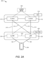
- FIG. 2A illustrates an example wireless network structure 200.
- a 5GC 210 also referred to as a Next Generation Core (NGC)
- C-plane control plane
- U-plane user plane
- User plane interface (NG-U) 213 and control plane interface (NG-C) 215 connect the gNB 222 to the 5GC 210 and specifically to the control plane functions 214 and user plane functions 212.
- an ng-eNB 224 may also be connected to the 5GC 210 via NG-C 215 to the control plane functions 214 and NG-U 213 to user plane functions 212. Further, ng-eNB 224 may directly communicate with gNB 222 via a backhaul connection 223. In some configurations, the New RAN 220 may only have one or more gNBs 222, while other configurations include one or more of both ng-eNBs 224 and gNBs 222. Either gNB 222 or ng-eNB 224 may communicate with UEs 204 (e.g., any of the UEs depicted in FIG. 1 ).
- location server 230 may be in communication with the 5GC 210 to provide location assistance for UEs 204.
- the location server 230 can be implemented as a plurality of separate servers (e.g., physically separate servers, different software modules on a single server, different software modules spread across multiple physical servers, etc.), or alternately may each correspond to a single server.
- the location server 230 can be configured to support one or more location services for UEs 204 that can connect to the location server 230 via the core network, 5GC 210, and/or via the Internet (not illustrated). Further, the location server 230 may be integrated into a component of the core network, or alternatively may be external to the core network.
- FIG. 2B illustrates another example wireless network structure 250.
- a 5GC 260 can be viewed functionally as control plane functions, provided by an access and mobility management function (AMF) 264, and user plane functions, provided by a user plane function (UPF) 262, which operate cooperatively to form the core network (i.e., 5GC 260).
- AMF access and mobility management function
- UPF user plane function
- User plane interface 263 and control plane interface 265 connect the ng-eNB 224 to the 5GC 260 and specifically to UPF 262 and AMF 264, respectively.
- a gNB 222 may also be connected to the 5GC 260 via control plane interface 265 to AMF 264 and user plane interface 263 to UPF 262.
- ng-eNB 224 may directly communicate with gNB 222 via the backhaul connection 223, with or without gNB direct connectivity to the 5GC 260.
- the New RAN 220 may only have one or more gNBs 222, while other configurations include one or more of both ng-eNBs 224 and gNBs 222.
- Either gNB 222 or ng-eNB 224 may communicate with UEs 204 (e.g., any of the UEs depicted in FIG. 1 ).
- the base stations of the New RAN 220 communicate with the AMF 264 over the N2 interface and with the UPF 262 over the N3 interface.
- the functions of the AMF 264 include registration management, connection management, reachability management, mobility management, lawful interception, transport for session management (SM) messages between the LTE 204 and a session management function (SMF) 266, transparent proxy services for routing SM messages, access authentication and access authorization, transport for short message service (SMS) messages between the UE 204 and the short message service function (SMSF) (not shown), and security anchor functionality (SEAF).
- SM session management
- SMF session management function
- SMF short message service
- SEAF security anchor functionality
- the AMF 264 also interacts with an authentication server function (AUSF) (not shown) and the UE 204, and receives the intermediate key that was established as a result of the UE 204 authentication process.
- AUSF authentication server function
- the AMF 264 retrieves the security material from the AUSF.
- the functions of the AMF 264 also include security context management (SCM).
- SCM receives a key from the SEAF that it uses to derive access-network specific keys.
- the functionality of the AMF 264 also includes location services management for regulatory services, transport for location services messages between the UE 204 and a location management function (LMF) 270 (which acts as a location server 230), transport for location services messages between the New RAN 220 and the LMF 270, evolved packet system (EPS) bearer identifier allocation for interworking with the EPS, and UE 204 mobility event notification.
- LMF location management function
- EPS evolved packet system
- the AMF 264 also supports functionalities for non-3GPP access networks.
- Functions of the UPF 262 include acting as an anchor point for intra-/inter-RAT mobility (when applicable), acting as an external protocol data unit (PDU) session point of interconnect to a data network (not shown), providing packet routing and forwarding, packet inspection, user plane policy rule enforcement (e.g., gating, redirection, traffic steering), lawful interception (user plane collection), traffic usage reporting, quality of service (QoS) handling for the user plane (e.g., uplink/downlink rate enforcement, reflective QoS marking in the downlink), uplink traffic verification (service data flow (SDF) to QoS flow mapping), transport level packet marking in the uplink and downlink, downlink packet buffering and downlink data notification triggering, and sending and forwarding of one or more "end markers" to the source RAN node.
- the UPF 262 may also support transfer of location services messages over a user plane between the UE 204 and a location server, such as a secure user plane location (SUPL) location platform (SLP) 272.
- the functions of the SMF 266 include session management, LTE Internet protocol (IP) address allocation and management, selection and control of user plane functions, configuration of traffic steering at the UPF 262 to route traffic to the proper destination, control of part of policy enforcement and QoS, and downlink data notification.
- IP Internet protocol
- the interface over which the SMF 266 communicates with the AMF 264 is referred to as the N11 interface.
- LMF 270 may be in communication with the 5GC 260 to provide location assistance for UEs 204.
- the LMF 270 can be implemented as a plurality of separate servers (e.g., physically separate servers, different software modules on a single server, different software modules spread across multiple physical servers, etc.), or alternately may each correspond to a single server.
- the LMF 270 can be configured to support one or more location services for UEs 204 that can connect to the LMF 270 via the core network, 5GC 260, and/or via the Internet (not illustrated).
- the SLP 272 may support similar functions to the LMF 270, but whereas the LMF 270 may communicate with the AMF 264, New RAN 220, and UEs 204 over a control plane (e.g., using interfaces and protocols intended to convey signaling messages and not voice or data), the SLP 272 may communicate with UEs 204 and external clients (not shown in FIG. 2B ) over a user plane (e.g., using protocols intended to carry voice and/or data like the transmission control protocol (TCP) and/or IP).
- TCP transmission control protocol
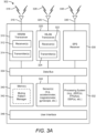
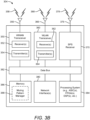
- FIGS. 3A , 3B , and 3C illustrate several exemplary components (represented by corresponding blocks) that may be incorporated into a LTE 302 (which may correspond to any of the UEs described herein), a base station 304 (which may correspond to any of the base stations described herein), and a network entity 306 (which may correspond to or embody any of the network functions described herein, including the location server 230, the LMF 270, and the SLP 272) to support the file transmission operations as taught herein.
- LTE 302 which may correspond to any of the UEs described herein
- a base station 304 which may correspond to any of the base stations described herein
- a network entity 306 which may correspond to or embody any of the network functions described herein, including the location server 230, the LMF 270, and the SLP 272 to support the file transmission operations as taught herein.
- these components may be implemented in different types of apparatuses in different implementations (e.g., in an ASIC, in a system-
- the illustrated components may also be incorporated into other apparatuses in a communication system.
- other apparatuses in a system may include components similar to those described to provide similar functionality.
- a given apparatus may contain one or more of the components.
- an apparatus may include multiple transceiver components that enable the apparatus to operate on multiple carriers and/or communicate via different technologies.
- the LTE 302 and the base station 304 each include wireless wide area network (WWAN) transceivers 310 and 350, respectively, providing means for communicating (e.g., means for transmitting, means for receiving, means for measuring, means for tuning, means for refraining from transmitting, etc.) via one or more wireless communication networks (not shown), such as an NR network, an LTE network, a GSM network, and/or the like.
- WWAN wireless wide area network
- the WWAN transceivers 310 and 350 may be connected to one or more antennas 316 and 356, respectively, for communicating with other network nodes, such as other UEs, access points, base stations (e.g., ng-eNBs, gNBs), etc., via at least one designated RAT (e.g., NR, LTE, GSM, etc.) over a wireless communication medium of interest (e.g., some set of time/frequency resources in a particular frequency spectrum).
- a wireless communication medium of interest e.g., some set of time/frequency resources in a particular frequency spectrum.
- the WWAN transceivers 310 and 350 may be variously configured for transmitting and encoding signals 318 and 358 (e.g., messages, indications, information, and so on), respectively, and, conversely, for receiving and decoding signals 318 and 358 (e.g., messages, indications, information, pilots, and so on), respectively, in accordance with the designated RAT.
- the WWAN transceivers 310 and 350 include one or more transmitters 314 and 354, respectively, for transmitting and encoding signals 318 and 358, respectively, and one or more receivers 312 and 352, respectively, for receiving and decoding signals 318 and 358, respectively.
- the LTE 302 and the base station 304 also include, at least in some cases, wireless local area network (WLAN) transceivers 320 and 360, respectively.
- the WLAN transceivers 320 and 360 may be connected to one or more antennas 326 and 366, respectively, and provide means for communicating (e.g., means for transmitting, means for receiving, means for measuring, means for tuning, means for refraining from transmitting, etc.) with other network nodes, such as other UEs, access points, base stations, etc., via at least one designated RAT (e.g., WiFi, LTE-D, Bluetooth ® , etc.) over a wireless communication medium of interest.
- RAT e.g., WiFi, LTE-D, Bluetooth ®
- the WLAN transceivers 320 and 360 may be variously configured for transmitting and encoding signals 328 and 368 (e.g., messages, indications, information, and so on), respectively, and, conversely, for receiving and decoding signals 328 and 368 (e.g., messages, indications, information, pilots, and so on), respectively, in accordance with the designated RAT.
- the WLAN transceivers 320 and 360 include one or more transmitters 324 and 364, respectively, for transmitting and encoding signals 328 and 368, respectively, and one or more receivers 322 and 362, respectively, for receiving and decoding signals 328 and 368, respectively.
- Transceiver circuitry including at least one transmitter and at least one receiver may comprise an integrated device (e.g., embodied as a transmitter circuit and a receiver circuit of a single communication device) in some implementations, may comprise a separate transmitter device and a separate receiver device in some implementations, or may be embodied in other ways in other implementations.
- a transmitter may include or be coupled to a plurality of antennas (e.g., antennas 316, 326, 356, 366), such as an antenna array, that permits the respective apparatus to perform transmit "beamforming," as described herein.
- a receiver may include or be coupled to a plurality of antennas (e.g., antennas 316, 326, 356, 366), such as an antenna array, that permits the respective apparatus to perform receive beamforming, as described herein.
- the transmitter and receiver may share the same plurality of antennas (e.g., antennas 316, 326, 356, 366), such that the respective apparatus can only receive or transmit at a given time, not both at the same time.
- a wireless communication device e.g., one or both of the transceivers 310 and 320 and/or 350 and 360) of the UE 302 and/or the base station 304 may also comprise a network listen module (NLM) or the like for performing various measurements.
- NLM network listen module
- the UE 302 and the base station 304 also include, at least in some cases, satellite positioning systems (SPS) receivers 330 and 370.
- SPS satellite positioning systems
- the SPS receivers 330 and 370 may be connected to one or more antennas 336 and 376, respectively, and may provide means for receiving and/or measuring SPS signals 338 and 378, respectively, such as global positioning system (GPS) signals, global navigation satellite system (GLONASS) signals, Galileo signals, Beidou signals, Indian Regional Navigation Satellite System (NAVIC), Quasi-Zenith Satellite System (QZSS), etc.
- the SPS receivers 330 and 370 may comprise any suitable hardware and/or software for receiving and processing SPS signals 338 and 378, respectively.
- the SPS receivers 330 and 370 request information and operations as appropriate from the other systems, and performs calculations necessary to determine positions of the LTE 302 and the base station 304 using measurements obtained by any suitable SPS algorithm.
- the base station 304 and the network entity 306 each include at least one network interfaces 380 and 390, respectively, providing means for communicating (e.g., means for transmitting, means for receiving, etc.) with other network entities.
- the network interfaces 380 and 390 e.g., one or more network access ports
- the network interfaces 380 and 390 may be implemented as transceivers configured to support wire-based or wireless signal communication. This communication may involve, for example, sending and receiving messages, parameters, and/or other types of information.
- the UE 302, the base station 304, and the network entity 306 also include other components that may be used in conjunction with the operations as disclosed herein.
- the UE 302 includes processor circuitry implementing a processing system 332 for providing functionality relating to, for example, positioning operations, and for providing other processing functionality.
- the base station 304 includes a processing system 384 for providing functionality relating to, for example, positioning operations as disclosed herein, and for providing other processing functionality.
- the network entity 306 includes a processing system 394 for providing functionality relating to, for example, positioning operations as disclosed herein, and for providing other processing functionality.
- the processing systems 332, 384, and 394 may therefore provide means for processing, such as means for determining, means for calculating, means for receiving, means for transmitting, means for indicating, etc.
- processing systems 332, 384, and 394 may include, for example, one or more general purpose processors, multi-core processors, ASICs, digital signal processors (DSPs), field programmable gate arrays (FPGA), or other programmable logic devices or processing circuitry.
- general purpose processors multi-core processors
- ASICs application-specific integrated circuits
- DSPs digital signal processors
- FPGA field programmable gate arrays
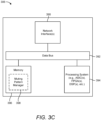
- the UE 302, the base station 304, and the network entity 306 include memory circuitry implementing memory components 340, 386, and 396 (e.g., each including a memory device), respectively, for maintaining information (e.g., information indicative of reserved resources, thresholds, parameters, and so on).
- the memory components 340, 386, and 396 may therefore provide means for storing, means for retrieving, means for maintaining, etc.
- the UE 302, the base station 304, and the network entity 306 may include muting pattern managers 342, 388, and 398, respectively.
- the muting pattern managers 342, 388, and 398 may be hardware circuits that are part of or coupled to the processing systems 332, 384, and 394, respectively, that, when executed, cause the UE 302, the base station 304, and the network entity 306 to perform the functionality described herein.
- the muting pattern managers 342, 388, and 398 may be external to the processing systems 332, 384, and 394 (e.g., part of a modem processing system, integrated with another processing system, etc.).
- the muting pattern managers 342, 388, and 398 may be memory modules (as shown in FIGS.
- 3A-C stored in the memory components 340, 386, and 396, respectively, that, when executed by the processing systems 332, 384, and 394 (or a modem processing system, another processing system, etc.), cause the UE 302, the base station 304, and the network entity 306 to perform the functionality described herein.
- the UE 302 may include one or more sensors 344 coupled to the processing system 332 to provide means for sensing or detecting movement and/or orientation information that is independent of motion data derived from signals received by the WWAN transceiver 310, the WLAN transceiver 320, and/or the SPS receiver 330.
- the sensor(s) 344 may include an accelerometer (e.g., a micro-electrical mechanical systems (MEMS) device), a gyroscope, a geomagnetic sensor (e.g., a compass), an altimeter (e.g., a barometric pressure altimeter), and/or any other type of movement detection sensor.
- MEMS micro-electrical mechanical systems
- the senor(s) 344 may include a plurality of different types of devices and combine their outputs in order to provide motion information.
- the sensor(s) 344 may use a combination of a multiaxis accelerometer and orientation sensors to provide the ability to compute positions in 2D and/or 3D coordinate systems.
- the LTE 302 includes a user interface 346 providing means for providing indications (e.g., audible and/or visual indications) to a user and/or for receiving user input (e.g., upon user actuation of a sensing device such a keypad, a touch screen, a microphone, and so on).
- a user interface 346 providing means for providing indications (e.g., audible and/or visual indications) to a user and/or for receiving user input (e.g., upon user actuation of a sensing device such a keypad, a touch screen, a microphone, and so on).
- the base station 304 and the network entity 306 may also include user interfaces.
- IP packets from the network entity 306 may be provided to the processing system 384.
- the processing system 384 may implement functionality for an RRC layer, a packet data convergence protocol (PDCP) layer, a radio link control (RLC) layer, and a medium access control (MAC) layer.
- PDCP packet data convergence protocol
- RLC radio link control
- MAC medium access control
- the processing system 384 may provide RRC layer functionality associated with broadcasting of system information (e.g., master information block (MIB), system information blocks (SIBs)), RRC connection control (e.g., RRC connection paging, RRC connection establishment, RRC connection modification, and RRC connection release), inter-RAT mobility, and measurement configuration for UE measurement reporting; PDCP layer functionality associated with header compression/decompression, security (ciphering, deciphering, integrity protection, integrity verification), and handover support functions; RLC layer functionality associated with the transfer of upper layer packet data units (PDUs), error correction through automatic repeat request (ARQ), concatenation, segmentation, and reassembly of RLC service data units (SDUs), re-segmentation of RLC data PDUs, and reordering of RLC data PDUs; and MAC layer functionality associated with mapping between logical channels and transport channels, scheduling information reporting, error correction, priority handling, and logical channel prioritization.
- RRC connection control e.g.
- the transmitter 354 and the receiver 352 may implement Layer-1 functionality associated with various signal processing functions.
- Layer-1 which includes a physical (PHY) layer, may include error detection on the transport channels, forward error correction (FEC) coding/decoding of the transport channels, interleaving, rate matching, mapping onto physical channels, modulation/demodulation of physical channels, and MIMO antenna processing.
- FEC forward error correction
- the transmitter 354 handles mapping to signal constellations based on various modulation schemes (e.g., binary phase-shift keying (BPSK), quadrature phase-shift keying (QPSK), M-phase-shift keying (M-PSK), M-quadrature amplitude modulation (M-QAM)).
- BPSK binary phase-shift keying
- QPSK quadrature phase-shift keying
- M-PSK M-phase-shift keying
- M-QAM M-quadrature amplitude modulation
- Each stream may then be mapped to an orthogonal frequency division multiplexing (OFDM) subcarrier, multiplexed with a reference signal (e.g., pilot) in the time and/or frequency domain, and then combined together using an inverse fast Fourier transform (IFFT) to produce a physical channel carrying a time domain OFDM symbol stream.
- OFDM symbol stream is spatially precoded to produce multiple spatial streams.
- Channel estimates from a channel estimator may be used to determine the coding and modulation scheme, as well as for spatial processing.
- the channel estimate may be derived from a reference signal and/or channel condition feedback transmitted by the UE 302.
- Each spatial stream may then be provided to one or more different antennas 356.
- the transmitter 354 may modulate an RF carrier with a respective spatial stream for transmission.
- the receiver 312 receives a signal through its respective antenna(s) 316.
- the receiver 312 recovers information modulated onto an RF carrier and provides the information to the processing system 332.
- the transmitter 314 and the receiver 312 implement Layer-1 functionality associated with various signal processing functions.
- the receiver 312 may perform spatial processing on the information to recover any spatial streams destined for the UE 302. If multiple spatial streams are destined for the UE 302, they may be combined by the receiver 312 into a single OFDM symbol stream.
- the receiver 312 then converts the OFDM symbol stream from the time-domain to the frequency domain using a fast Fourier transform (FFT).
- FFT fast Fourier transform
- the frequency domain signal comprises a separate OFDM symbol stream for each subcarrier of the OFDM signal.
- the symbols on each subcarrier, and the reference signal are recovered and demodulated by determining the most likely signal constellation points transmitted by the base station 304. These soft decisions may be based on channel estimates computed by a channel estimator. The soft decisions are then decoded and de-interleaved to recover the data and control signals that were originally transmitted by the base station 304 on the physical channel. The data and control signals are then provided to the processing system 332, which implements Layer-3 and Layer-2 functionality.
- the processing system 332 provides demultiplexing between transport and logical channels, packet reassembly, deciphering, header decompression, and control signal processing to recover IP packets from the core network.
- the processing system 332 is also responsible for error detection.
- the processing system 332 provides RRC layer functionality associated with system information (e.g., MIB, SIBs) acquisition, RRC connections, and measurement reporting; PDCP layer functionality associated with header compression/decompression, and security (ciphering, deciphering, integrity protection, integrity verification); RLC layer functionality associated with the transfer of upper layer PDUs, error correction through ARQ, concatenation, segmentation, and reassembly of RLC SDUs, re-segmentation of RLC data PDUs, and reordering of RLC data PDUs; and MAC layer functionality associated with mapping between logical channels and transport channels, multiplexing of MAC SDUs onto transport blocks (TBs), demultiplexing of MAC SDUs from TBs, scheduling information reporting, error correction through hybrid automatic repeat request (HARQ), priority handling, and logical channel prioritization.
- RRC layer functionality associated with system information (e.g., MIB, SIBs) acquisition, RRC connections, and measurement reporting
- PDCP layer functionality associated
- Channel estimates derived by the channel estimator from a reference signal or feedback transmitted by the base station 304 may be used by the transmitter 314 to select the appropriate coding and modulation schemes, and to facilitate spatial processing.
- the spatial streams generated by the transmitter 314 may be provided to different antenna(s) 316.
- the transmitter 314 may modulate an RF carrier with a respective spatial stream for transmission.
- the uplink transmission is processed at the base station 304 in a manner similar to that described in connection with the receiver function at the UE 302.
- the receiver 352 receives a signal through its respective antenna(s) 356.
- the receiver 352 recovers information modulated onto an RF carrier and provides the information to the processing system 384.
- the processing system 384 provides demultiplexing between transport and logical channels, packet reassembly, deciphering, header decompression, control signal processing to recover IP packets from the UE 302. IP packets from the processing system 384 may be provided to the core network.
- the processing system 384 is also responsible for error detection.
- the UE 302, the base station 304, and/or the network entity 306 are shown in FIGS. 3A-C as including various components that may be configured according to the various examples described herein. It will be appreciated, however, that the illustrated blocks may have different functionality in different designs.
- the various components of the UE 302, the base station 304, and the network entity 306 may communicate with each other over data buses 334, 382, and 392, respectively.
- the components of FIGS. 3A-C may be implemented in various ways.
- the components of FIGS. 3A-C may be implemented in one or more circuits such as, for example, one or more processors and/or one or more ASICs (which may include one or more processors).
- each circuit may use and/or incorporate at least one memory component for storing information or executable code used by the circuit to provide this functionality.
- some or all of the functionality represented by blocks 310 to 346 may be implemented by processor and memory component(s) of the UE 302 (e.g., by execution of appropriate code and/or by appropriate configuration of processor components).
- some or all of the functionality represented by blocks 350 to 388 may be implemented by processor and memory component(s) of the base station 304 (e.g., by execution of appropriate code and/or by appropriate configuration of processor components).
- some or all of the functionality represented by blocks 390 to 398 may be implemented by processor and memory component(s) of the network entity 306 (e.g., by execution of appropriate code and/or by appropriate configuration of processor components).
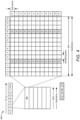
- FIG. 4 is a diagram 400 illustrating an example of a downlink frame structure, according to aspects of the disclosure.
- Other wireless communications technologies may have different frame structures and/or different channels.
- LTE and in some cases NR, utilizes OFDM on the downlink and single-carrier frequency division multiplexing (SC-FDM) on the uplink.
- SC-FDM single-carrier frequency division multiplexing
- OFDM and SC-FDM partition the system bandwidth into multiple (K) orthogonal subcarriers, which are also commonly referred to as tones, bins, etc.
- K multiple orthogonal subcarriers
- Each subcarrier may be modulated with data.
- modulation symbols are sent in the frequency domain with OFDM and in the time domain with SC-FDM.
- the spacing between adjacent subcarriers may be fixed, and the total number of subcarriers (K) may be dependent on the system bandwidth.
- the spacing of the subcarriers may be 15 kHz and the minimum resource allocation (resource block) may be 12 subcarriers (or 180 kHz). Consequently, the nominal FFT size may be equal to 128, 256, 512, 1024, or 2048 for system bandwidth of 1.25, 2.5, 5, 10, or 20 megahertz (MHz), respectively.
- the system bandwidth may also be partitioned into subbands. For example, a subband may cover 1.08 MHz (i.e., 6 resource blocks), and there may be 1, 2, 4, 8, or 16 subbands for system bandwidth of 1.25, 2.5, 5, 10, or 20 MHz, respectively.
- LTE supports a single numerology (subcarrier spacing, symbol length, etc.).
- NR may support multiple numerologies ( ⁇ ), for example, subcarrier spacing of 15 kHz, 30 kHz, 60 kHz, 120 kHz, and 240 kHz or greater may be available.
- Table 1 provided below lists some various parameters for different NR numerologies. Table 1 ⁇ SCS (kHz) Symbols / Sot Slots / Subframe Slots / Frame Slot Duration (ms) Symbol Duration ( ⁇ s) Max.
- a numerology of 15 kHz is used.
- a frame e.g., 10 ms
- each subframe includes one time slot.
- time is represented horizontally (e.g., on the X axis) with time increasing from left to right
- frequency is represented vertically (e.g., on the Y axis) with frequency increasing (or decreasing) from bottom to top.
- a resource grid may be used to represent time slots, each time slot including one or more time-concurrent resource blocks (RBs) (also referred to as physical RBs (PRBs)) in the frequency domain.
- the resource grid is further divided into multiple resource elements (REs).
- An RE may correspond to one symbol length in the time domain and one subcarrier in the frequency domain.
- an RB may contain 12 consecutive subcarriers in the frequency domain and seven consecutive symbols in the time domain, for a total of 84 REs.
- an RB may contain 12 consecutive subcarriers in the frequency domain and six consecutive symbols in the time domain, for a total of 72 REs.
- the number of bits carried by each RE depends on the modulation scheme.
- the DL-RS may include demodulation reference signals (DMRS), channel state information reference signals (CSI-RS), cell-specific reference signals (CRS), positioning reference signals (PRS), navigation reference signals (NRS), tracking reference signals (TRS), etc., exemplary locations of which are labeled "R" in FIG. 4 .
- DMRS demodulation reference signals
- CSI-RS channel state information reference signals
- CRS cell-specific reference signals
- PRS positioning reference signals
- NRS navigation reference signals
- TRS tracking reference signals
- a collection of resource elements (REs) that are used for transmission of PRS is referred to as a "PRS resource.”
- the collection of resource elements can span multiple PRBs in the frequency domain and N (e.g., 1 or more) consecutive symbol(s) within a slot in the time domain.
- N e.g., 1 or more
- a PRS resource occupies consecutive PRBs in the frequency domain.
- a "PRS resource set” is a set of PRS resources used for the transmission of PRS signals, where each PRS resource has a PRS resource ID.
- the PRS resources in a PRS resource set are associated with the same TRP.
- a PRS resource set is identified by a PRS resource set ID and is associated with a particular TRP (identified by a cell ID).
- the PRS resources in a PRS resource set have the same periodicity, a common muting pattern configuration, and the same repetition factor across slots.
- the repetition factor may have a length selected from ⁇ 1, 2, 4, 6, 8, 16, 32 ⁇ slots.
- a PRS resource ID in a PRS resource set is associated with a single beam (and/or a beam ID) transmitted from a single TRP (where a TRP may transmit one or more beams). That is, each PRS resource of a PRS resource set may be transmitted on a different beam, and as such, a "PRS resource,” or simply “resource,” can also be referred to as a "beam.” Note that this does not have any implications on whether the TRPs and the beams on which PRS are transmitted are known to the UE.
- a “PRS instance” or “PRS occasion” is one instance of a periodically repeated time window (e.g., a group of one or more consecutive slots) where PRS are expected to be transmitted.
- a PRS occasion may also be referred to as a "PRS positioning occasion,” a “PRS positioning instance, a “positioning occasion,” a “positioning instance,” a “repetition of PRS resources,” or simply an “occasion,” an “instance,” or a "repetition.”
- positioning reference signal and “PRS” may sometimes refer to specific reference signals that are used for positioning in LTE systems.
- positioning reference signal and “PRS” refer to any type of reference signal that can be used for positioning, such as but not limited to, PRS in LTE, NRS in 5G, TRS, CRS, CSI-RS, DMRS, PSS, SSS, SSB, etc.
- the first alternative is that the periodicity of downlink PRS resources is configured at the downlink PRS resource set level. In this case, a common period is used for downlink PRS resources within a downlink PRS resource set.
- the second alternative is that the periodicity of downlink PRS resources is configured at the downlink PRS resource level. In this case, different periods can be used for downlink PRS resources within a downlink PRS resource set.
- FIG. 5 illustrates an exemplary PRS configuration 500 for a cell/TRP supported by a wireless node (e.g., a base station).
- FIG. 5 shows how PRS positioning occasions are determined by a system frame number (SFN), a cell-specific subframe offset ( ⁇ PRS ) 552, and a PRS periodicity ( T PRS ) 520.
- the cell-specific PRS subframe configuration is defined by a PRS configuration index ( I PRS ) included in positioning assistance data.
- the PRS periodicity ( T PRS ) 520 and the cell-specific subframe offset ( ⁇ PRS ) are defined based on the PRS configuration index ( I PRS ), as illustrated in Table 2 below.
- PRS configuration Index I PRS PRS periodicity T PRS ( subframes ) PRS subframe offset ⁇ PRS (subframes) 0 - 159 160 I PRS 160 - 479 320 I PRS -160 480 - 1119 640 I PRS -480 1120 - 2399 1280 I PRS -1120 2400 - 2404 5 I PRS - 2400 2405 - 2414 10 I PRS - 2405 2415 - 2434 20 I PRS - 2415 2435 - 2474 40 I PRS -2435 2475 - 2554 80 I PRS - 2475 2555-4095 Reserved
- a PRS configuration is defined with reference to the SFN of the cell that transmits PRS.
- the number of consecutive positioning subframes ( N PRS ) in each of the consecutive PRS positioning occasions 518a, 518b, and 518c equals 4.
- N PRS may specify the number of consecutive positioning subframes per occasion, it may instead specify the number of consecutive positioning slots, based on implementation. For example, in LTE, N PRS specifies the number of consecutive positioning subframes per occasion, whereas in NR, N PRS specifies the number of consecutive positioning slots per occasion.
- the LTE may determine the PRS periodicity ( T PRS ) 520 and PRS subframe offset ⁇ PRS using Table 2.
- the UE may then determine the radio frame, subframe, and slot when a PRS is scheduled in the cell (e.g., using the equation above).
- the positioning assistance data may be determined by, for example, the location server, and include assistance data for a reference cell and a number of neighbor cells supported by various wireless nodes.
- PRS occasions from all cells in a network that use the same frequency are aligned in time and may have a fixed known time offset (e.g., cell-specific subframe offset 552) relative to other cells in the network that use a different frequency.
- all wireless nodes e.g., base stations
- all cells supported by the various wireless nodes may use the same PRS configuration index I PRS for any particular frequency of PRS transmission.
- the various wireless nodes may be aligned on a frame boundary, but not system frame number.
- the PRS configuration index I PRS for each cell may be configured separately by the network so that PRS occasions align in time.
- a UE may determine the timing of the PRS occasions of the reference and neighbor cells for positioning, if the UE can obtain the cell timing (e.g., SFN) of at least one of the cells, such as a reference cell or a serving cell.
- the timing of the other cells may then be derived by the UE based, for example, on the assumption that PRS occasions from different cells overlap.
- the sequence of subframes used to transmit PRS may be characterized and defined by a number of parameters, comprising: (i) a reserved block of bandwidth (BW), (ii) the PRS configuration index I PRS , (iii) the duration N PRS , (iv) an optional muting pattern, and (v) a muting sequence periodicity T REP that can be implicitly included as part of the muting pattern in (iv) when present.
- BW 1.4, 3, 5, 10, 15, or 20 MHz.
- An expanded PRS with a larger N PRS (e.g., greater than six) and/or a shorter T PRS (e.g., less than 160 ms), up to the full duty cycle (i.e., N PRS T PRS ), may also be used in later versions of the LTE positioning protocol (LPP).
- FIG. 6 illustrates an exemplary PRS configuration 600 that includes a PRS muting sequence (also referred to as a "muting pattern"), according to aspects of the disclosure.
- FIG. 6 shows how PRS positioning occasions are determined by an SFN, a cell-specific subframe offset ( ⁇ PRS ) 652, and the PRS Periodicity ( T PRS ) 620.
- the number of consecutive positioning subframes ( N PRS ) in each of the consecutive PRS positioning occasions 618a and 618b equals four.
- PRS are generally transmitted with a constant power.
- a PRS can also be transmitted with zero power (i.e., muted). Muting, which turns off a regularly scheduled PRS transmissions, may be useful when PRS between different cells overlap by occurring at the same or almost the same time. In this case, the PRS from some cells may be muted while PRS from other cells are transmitted (e.g., at a constant power). Muting may aid signal acquisition and time of arrival (ToA) and reference signal time difference (RSTD) measurements, by UEs, of PRS that are not muted (by avoiding interference from PRS that have been muted).
- ToA signal acquisition and time of arrival
- RSTD reference signal time difference
- the (strong) PRS the LTE receives from one base station is muted
- the (weak) PRS from a neighboring base station (with the same frequency shift) can be more easily detected by the LTE.
- Muting may be viewed as the non-transmission of a PRS for a given positioning occasion for a particular cell. Muting patterns may be signaled to a LTE using bit strings having a length of 2, 4, 8, or 16 bits (corresponding to the selected T REP ). If a bit in the bit string is set to ⁇ 0,' then the UE infers that all PRS are muted in the corresponding positioning occasion.
- the muting sequence periodicity T REP 630 includes two consecutive PRS positioning occasions 618a and 618b followed by two consecutive muted PRS positioning occasions 618c and 618d.
- the PRS muting configuration of a cell is only defined by a periodic muting sequence (e.g., muting sequence periodicity T REP 630), as opposed to an aperiodic or semi-persistent muting sequence.
- the two consecutive PRS positioning occasions 618a and 618b followed by the two consecutive muted PRS positioning occasions 618c and 618d will repeat for the next muting sequence periodicity T REP 630.
- positioning subframes/slots may be low-interference subframes/slots that are transmitted without user data channels.
- PRS may receive interference from other cells' PRS with the same PRS pattern index (i.e., with the same frequency shift), but not from data transmissions.
- the frequency shift in LTE for example, is defined as a function of a PRS ID for a cell or other transmission point (TP) (denoted as N ID PRS ) or as a function of a PCI (denoted as N ID cell ) if no PRS ID is assigned, which results in an effective frequency re-use factor of six.
- the frequency band for consecutive PRS positioning occasions may be changed in a known and predictable manner via frequency hopping.
- a cell supported by a wireless node may support more than one PRS configuration (e.g., PRS configuration 500/600), where each PRS configuration may comprise a distinct frequency offset ( vshift ) , a distinct carrier frequency, a distinct bandwidth, a distinct code sequence, and/or a distinct sequence of PRS positioning occasions with a particular number of subframes ( N PRS ) per positioning occasion and a particular periodicity ( T PRS ).
- one or more of the PRS configurations supported in a cell may be for a directional PRS and may then have additional distinct characteristics such as a distinct direction of transmission, a distinct range of horizontal angles and/or a distinct range of vertical angles. Further enhancements of a PRS may also be supported by a wireless node.
- a PRS configuration as described above, including the PRS transmission/muting schedule, is signaled to the LTE to enable the LTE to perform PRS positioning measurements.
- the LTE is not expected to blindly perform detection of PRS configurations.
- a PRS configuration (e.g., PRS configuration 500/600) was initially signaled with 16 bits, and later with 1024 bits.
- the bits of a PRS configuration (whether 16 bits or 1024 bits) signal which PRS occasions are ON (i.e., active, not muted), after which the pattern repeats.
- a base station can configure one or more PRS resource sets, where each PRS resource set contains one or more PRS resources.
- a PRS resource set is associated with some periodicity T PRS .
- a PRS resource set may have up to 128 PRS resources, which could result in a 128-bit bitmap representing which PRS resources are ON and OFF (i.e., inactive, muted) in a specific PRS occasion.
- each bitmap equals the number of PRS resources in the PRS resource set (up to 128 bits), so that an indication of which beams are muted is provided for each PRS occasion.
- the foregoing could cause, in the worst case, very high configuration overhead in the positioning assistance data.
- FIG. 7 is a diagram of an exemplary PRS configuration 700 for the PRS transmissions of a given base station, according to aspects of the disclosure.
- time is represented horizontally, increasing from left to right.
- Each long rectangle represents a slot and each short (shaded) rectangle represents an OFDM symbol.
- the PRS configuration 700 identifies the PRS resources 712 and 714 of a PRS resource set 710 during which the base station transmits PRS.
- the PRS resource set 710 has an occasion length N PRS of two (2) slots and a periodicity of T PRS (e.g., 160 subframes or 160 ms).
- T PRS e.g. 160 subframes or 160 ms
- the PRS resource set 710 includes two PRS resources, a first PRS resource 712 (labeled "PRS resource 1" in FIG. 7 ) and a second PRS resource 714 (labeled "PRS resource 2" in FIG. 7 ).
- the PRS resource 712 and the PRS resource 714 may be transmitted on separate beams of the same base station.
- the PRS resource 712 has a symbol length N symb of two (2) symbols
- the PRS resource 714 has a symbol length N symb of four (4) symbols.
- the PRS resources 712 and 714 are repeated every T PRS subframes up to the muting sequence periodicity T REP .
- a bitmap of length T REP would be needed to indicate which occasions of instances 720a, 720b, and 720c are muted.
- PRS configuration 700 there may be additional constraints on a PRS configuration, such as PRS configuration 700 illustrated in FIG. 7 .
- the base station can configure the following parameters to be the same: (a) the occasion length (e.g., T PRS ), (b) the number of symbols (e.g., N symb ) , (c) the comb type, and/or (d) the bandwidth.
- the subcarrier spacing and the cyclic prefix can be configured to be the same for one base station or for all base stations. Whether it is for one base station or all base stations may depend on the UE's capability to support the subcarrier spacing and the cyclic prefix being the same for one base station or for all base stations.
- a muting pattern can be assigned across PRS occasions that controls the muting of a specific subgroup of PRS resources (e.g., PRS resources 712, 714) of the PRS resource set for each PRS occasion.
- a subgroup of PRS resources also referred to as a repetition of PRS resources
- a bitmap of some size 'X' can be configured for each subgroup of the PRS resource set, where the base station repeats the muting pattern in that PRS resource set after X PRS occasions.
- a subgroup may contain all the PRS resources of a PRS resource set (e.g., both PRS resources 712 and 714), which would result in the same muting pattern across time for all of the beams of that PRS resource set of that base station.
- This configuration would result in a small configuration overhead, but low flexibility.
- each subgroup may contain only one PRS resource (e.g., one of PRS resources 712 and 714), in which case, the PRS resource set would contain Y subgroups, where 'Y' is the number of PRS resources in the PRS resource set, and the PRS transmitted on each beam would have a different muting pattern. This configuration would result in a large configuration overhead but high flexibility.
- FIG. 8 illustrates a table 800 of an exemplary muting pattern for a given PRS resource set i , according to aspects of the disclosure.
- the columns of table 800 correspond to the subgroups of PRS resources in the PRS resource set i (labeled as "PRS Group ID"), and are numbered from '0' to N group i ⁇ 1 .
- the rows of table 800 correspond to the PRS occasions within the subgroups of PRS resources in the PRS resource set i (labeled "OCC ID"), and are numbered from ⁇ 0' to N occasions i ⁇ 1 .
- the values N occasions i and N group i are configurable (i.e., can be different) for each PRS resource set of each base station.
- the contents (i.e., the values in the rows) of each of the N group i subgroups of PRS resources are configurable (i.e., can be different) for each PRS resource set.
- a first subgroup of PRS resources of the PRS resource set 710 may contain the first PRS resource 712, and a second subgroup of PRS resources may contain the second PRS resource 714.
- the UE would be configured with two muting pattern bitmaps, one for each subgroup, allowing the two subgroups to be ON (e.g., active, not muted) or OFF (i.e., inactive, muted) independent of each other. That is, in some occasions, first PRS resource 712 may be transmitted and second PRS resource 714 may be muted, or vice versa, or both may be muted, or both may be transmitted. Note that each subgroup will still have an N PRS of '2' and a periodicity of T PRS .
- a PRS resource set is defined as a collection of PRS resources (or beams) with the same periodicity.
- the LTE may be able to report a positioning resource indication (PRI) related to which beam is the best inside the PRS resource set.
- PRI positioning resource indication
- a base station may transmit a PRS resource set of 16 PRS resources on 16 transmit beams, and every fourth beam may already be considered highly spatially separated, and therefore do not interfere with each other (meaning they are spatially muted).
- the base station can group every fourth beam into a subgroup of PRS resources, for a total of four subgroups. All that is needed then is to provide time-domain muting across the four PRS subgroups.
- the base station can provide the LTE with four N occasions -bit bitmaps, one for each PRS subgroup, rather than having to provide 16 X-bit bitmaps (i.e., one for each PRS resource) in which the muting pattern for every fourth PRS resource/beam is exactly the same.
- subgroups of PRS resources may only be created when the X-bit muting pattern has an X larger than a threshold.
- not providing any subgroups in the PRS muting configuration can be interpreted as either all PRS resources being in the same group, or each PRS resource being in its own group.
- the base station can assign a muting pattern across PRS occasions that controls the muting of each subgroup of PRS resources of each PRS resource set of that base station that has the given periodicity. More specifically, the number of PRS subgroups N group i may be configurable for each periodicity, and the number of PRS occasions N occasions i may be configurable for each PRS resource set.
- the base station can configure an N occasions i ⁇ bit bitmap for each subgroup of each PRS resource set when the base station wants to repeat the muting pattern in that set after N occasions occasions.
- FIG. 9 illustrates a table 900 of an exemplary muting pattern for an ordered sequence of PRS resource sets with the same periodicity, according to aspects of the disclosure.
- the columns of table 900 correspond to the subgroups of PRS resources in the PRS resource sets.
- a first PRS resource set has N group 1 subgroups of PRS resources
- a second PRS resource set has N group 2 subgroups of PRS resources
- a third PRS resource set has N group 3 subgroups of PRS resources, and so on.
- the rows of table 900 correspond to the PRS occasions within the subgroups of PRS resources in the PRS resource sets, and are numbered from '0' to N occasions i ⁇ 1 .
- a PRS resource set with N resources PRS resources can be associated with up to N muting T REP -bit muting pattern(s), where each bit of the muting pattern bitmap indicates whether a corresponding PRS occasion of the associated subgroup of PRS resources of the PRS resource set is muted or not.
- N groups of ' 1' is supported
- N muting of '1' is supported
- T REP of ⁇ 2,4,8,16 ⁇ is supported. Note that it should be possible to configure the same N muting muting pattern(s) for all PRS resource sets of a base station even if they have different periodicities.
- a base station can provide one N occasions i ⁇ bit bitmap associated with the first PRS subgroup of a PRS resource set i (as in the first technique described herein) or of a periodicity (as in the second technique described herein).
- the UE can then derive the remaining N occasions i ⁇ bit bitmaps associated with the remaining PRS subgroups using a deterministic function (e.g., cyclic shift index, permutation index), a randomized function, or the like.
- a deterministic function e.g., cyclic shift index, permutation index
- FIG. 10 illustrates a table 1000 of an exemplary muting pattern for a given PRS resource set i , according to aspects of the disclosure.
- the columns of table 1000 correspond to the subgroups of PRS resources in the PRS resource set i (labeled as "PRS Group ID"), and are numbered from '0' to N group i ⁇ 1 .
- the rows of table 1000 correspond to the PRS occasions within the subgroups of PRS resources in the PRS resource set i (labeled "OCC ID”), and are numbered from '0' to N occasions i ⁇ 1 .
- the base station only transmits the first column of table 1000 as the muting pattern.
- the UE can then derive the remaining columns of table 1000.
- the LTE may use a deterministic function, such as a cyclic shift index, as shown in FIG. 11 .
- FIG. 11 illustrates a table 1100 of an exemplary muting pattern for a given PRS resource set i, according to aspects of the disclosure.
- the columns of table 1100 correspond to the subgroups of PRS resources in the PRS resource set i (labeled as "PRS Group ID”), and are numbered from '0' to N group i ⁇ 1 .
- the rows of table 1100 correspond to the PRS occasions within the subgroups of PRS resources in the PRS resource set i (labeled "OCC ID”), and are numbered from ⁇ 0' to N occasions i ⁇ 1
- the base station only transmits the first column of table 1100 as the muting pattern.
- the base station sends a parameter, c 1 , in the configuration, which may be a cyclic shift index or a permutation index.
- the muting pattern of each subgroup changes compared to the configured N occasions i ⁇ bit bitmap (i.e., the first column of table 1100), without the base station having to provide the bitmaps for each subgroup of PRS resources (i.e., the entire table 1100). For example, as shown in FIG.
- FIG. 12 illustrates a table 1200 of an exemplary muting pattern for a given PRS resource set i , according to aspects of the disclosure.
- the columns of table 1200 correspond to the subgroups of PRS resources in the PRS resource set i (labeled as "PRS Group ID”), and are numbered from '0' to N group i ⁇ 1 .
- the rows of table 1200 correspond to the PRS occasions within the subgroups of PRS resources in the PRS resource set i (labeled "OCC ID”), and are numbered from ⁇ 0' to N occasions i ⁇ 1 .
- the base station only transmits the first column of table 1200 as the muting pattern.
- the base station sends a parameter, c i , for each subgroup of PRS resources (i.e., each column of table 1200) in the configuration, which may be a cyclic shift index or a permutation index.
- the muting pattern of each subgroup changes compared to the configured N occasions i ⁇ bit bitmap (i.e., the first column of table 1200), without the base station having to provide the entire N occasions i ⁇ N group i ⁇ bit bitmap for all subgroups of PRS resources of the PRS resource set i (i.e., the entire table 1200).
- the UE can derive the muting patterns for the subsequent subgroups (or columns of table 1200) based on the parameter C i .
- the UE can apply the corresponding permutation to the first column of table 1200 to derive the remaining columns of table 1200. More specifically, there may be N occasions i ! (i.e., N occasions i factional) different permutations of muting patterns that can be configured for the N group subgroups of PRS occasions.
- the base station may determine which permutations are appropriate (e.g., which muting pattern permutations will provide good hearability for PRS) and signal the index values of such permutations to the UE as the parameters c i .
- the UE can then determine the muting pattern for the second PRS subgroup N group 1 by calculating or looking up the c 1 th permutation of the muting pattern for the first PRS subgroup N group 0 and using that permutation as the muting pattern for the second PRS subgroup N group 1 .
- the location server (e.g., location server 230, LMF 270, SLP 272) can signal the PRS configuration and muting pattern to the involved base stations over New Radio positioning protocol type A (NRPPa) or LTE positioning protocol type A (LPPa), and to the UE over LPP (e.g., in the PRS-Info message).
- NRPPa New Radio positioning protocol type A
- LPPa LTE positioning protocol type A
- FIG. 13 illustrates an exemplary method 1300 of wireless communication, according to aspects of the disclosure.
- the method 1300 may be performed by a UE, such as any of the UEs described herein.
- the UE receives, from a transmission point, a first PRS muting pattern for a first subgroup of PRS resources of a first PRS resource set, wherein the first PRS muting pattern comprises a plurality of N bits representing a plurality of N PRS occasions of the first subgroup of PRS resources, wherein each bit of the plurality of N bits represents a corresponding PRS occasion of the plurality of N PRS occasions of each PRS resource of the first subgroup of PRS resources, and wherein the plurality of N PRS occasions comprises a plurality of active (i.e., ON, not muted) PRS occasions of the first subgroup of PRS resources.
- operation 1310 may be performed by WWAN transceiver(s) 310, processing system 332, memory component 340, and/or muting pattern manager 342, any or all of which may be considered as means for performing this operation.
- the LTE measures, during at least one of the plurality of active PRS occasions of the first subgroup of PRS resources, PRS received from the transmission point.
- operation 1320 may be performed by WWAN transceiver(s) 310, processing system 332, memory component 340, and/or muting pattern manager 342, any or all of which may be considered as means for performing this operation.
- the method 1300 may further include (not shown) estimating, by the UE, a location of the UE based on the measured PRS.
- the UE may report the measured PRS to a positioning entity (e.g., location server 230, LMF 270) to enable the positioning entity to calculate a location of the UE.
- the PRS may be used (by the UE or the positioning entity) to estimate the location of the UE using various positioning techniques, such as multi-cell RTT, AoA/AoD, etc.
- FIG . 14 illustrates an exemplary method 1400 of wireless communication, according to aspects of the disclosure.
- the method 1400 may be performed by a transmission point, such as a base station (e.g., any of the base stations described herein), an antenna or antenna array of a base station, a RRH, a DAS, etc.
- a base station e.g., any of the base stations described herein
- an antenna or antenna array of a base station e.g., any of the base stations described herein
- a RRH e.g., any of the base stations described herein
- DAS e.g., a DAS, etc.
- the transmission point transmits, to a UE (e.g., any of the UEs described herein), a first PRS muting pattern for a first subgroup of PRS resources of a first PRS resource set, wherein the first PRS muting pattern comprises a plurality of N bits representing a plurality of N PRS occasions of the first subgroup of PRS resources, wherein each bit of the plurality of N bits represents a corresponding PRS occasion of the plurality of N PRS occasions of each PRS resource of the first subgroup of PRS resources, and wherein the plurality of N PRS occasions comprises a plurality of active PRS occasions of the first subgroup of PRS resources.
- a UE e.g., any of the UEs described herein
- operation 1410 may be performed by WWAN transceiver(s) 350, processing system 384, memory component 386, and/or muting pattern manager 388 as shown in FIGS. 3A-3C , any or all of which may be considered as means for performing this operation.
- the transmission point transmits PRS to the UE during at least one of the plurality of active PRS occasions of the first subgroup of PRS resources.
- operation 1420 may be performed by WWAN transceiver(s) 350, processing system 384, memory component 386, and/or muting pattern manager 388 as shown in FIGS. 3A-3C , any or all of which may be considered as means for performing this operation.
- a technical advantage of the methods illustrated in FIGS. 13 and 14 is to reduce the overhead of signaling muting pattern configurations for downlink PRS.
- a general purpose processor may be a microprocessor, but in the alternative, the processor may be any conventional processor, controller, microcontroller, or state machine.
- a processor may also be implemented as a combination of computing devices, for example, a combination of a DSP and a microprocessor, a plurality of microprocessors, one or more microprocessors in conjunction with a DSP core, or any other such configuration.
- a software module may reside in random access memory (RAM), flash memory, read-only memory (ROM), erasable programmable ROM (EPROM), electrically erasable programmable ROM (EEPROM), registers, hard disk, a removable disk, a CD-ROM, or any other form of storage medium known in the art.
- An exemplary storage medium is coupled to the processor such that the processor can read information from, and write information to, the storage medium.
- the storage medium may be integral to the processor.
- the processor and the storage medium may reside in an ASIC.
- the ASIC may reside in a user terminal (e.g., LTE).
- the processor and the storage medium may reside as discrete components in a user terminal.
- the functions described may be implemented in hardware, software, firmware, or any combination thereof. If implemented in software, the functions may be stored on or transmitted over as one or more instructions or code on a computer-readable medium.
- Computer-readable media includes both computer storage media and communication media including any medium that facilitates transfer of a computer program from one place to another.
- a storage media may be any available media that can be accessed by a computer.
- such computer-readable media can comprise RAM, ROM, EEPROM, CD-ROM or other optical disk storage, magnetic disk storage or other magnetic storage devices, or any other medium that can be used to carry or store desired program code in the form of instructions or data structures and that can be accessed by a computer.
- any connection is properly termed a computer-readable medium.
- the software is transmitted from a website, server, or other remote source using a coaxial cable, fiber optic cable, twisted pair, digital subscriber line (DSL), or wireless technologies such as infrared, radio, and microwave
- the coaxial cable, fiber optic cable, twisted pair, DSL, or wireless technologies such as infrared, radio, and microwave are included in the definition of medium.
- Disk and disc includes compact disc (CD), laser disc, optical disc, digital versatile disc (DVD), floppy disk and Blu-ray disc where disks usually reproduce data magnetically, while discs reproduce data optically with lasers. Combinations of the above should also be included within the scope of computer-readable media.
Landscapes
- Engineering & Computer Science (AREA)
- Signal Processing (AREA)
- Computer Networks & Wireless Communication (AREA)
- Quality & Reliability (AREA)
- Mobile Radio Communication Systems (AREA)
Applications Claiming Priority (4)
| Application Number | Priority Date | Filing Date | Title |
|---|---|---|---|
| GR20190100347 | 2019-08-12 | ||
| US16/990,609 US11395301B2 (en) | 2019-08-12 | 2020-08-11 | Muting pattern configuration options for downlink positioning reference signals (PRS) |
| EP20793488.6A EP4014421B1 (de) | 2019-08-12 | 2020-08-12 | Dämpfungsmusterkonfigurationsoptionen für downlink-positionierungsreferenzsignale (prs) |
| PCT/US2020/045961 WO2021030459A1 (en) | 2019-08-12 | 2020-08-12 | Muting pattern configuration options for downlink positioning reference signals(prs) |
Related Parent Applications (2)
| Application Number | Title | Priority Date | Filing Date |
|---|---|---|---|
| EP20793488.6A Division EP4014421B1 (de) | 2019-08-12 | 2020-08-12 | Dämpfungsmusterkonfigurationsoptionen für downlink-positionierungsreferenzsignale (prs) |
| EP20793488.6A Division-Into EP4014421B1 (de) | 2019-08-12 | 2020-08-12 | Dämpfungsmusterkonfigurationsoptionen für downlink-positionierungsreferenzsignale (prs) |
Publications (2)
| Publication Number | Publication Date |
|---|---|
| EP4246864A2 true EP4246864A2 (de) | 2023-09-20 |
| EP4246864A3 EP4246864A3 (de) | 2023-12-20 |
Family
ID=74567985
Family Applications (3)
| Application Number | Title | Priority Date | Filing Date |
|---|---|---|---|
| EP20793488.6A Active EP4014421B1 (de) | 2019-08-12 | 2020-08-12 | Dämpfungsmusterkonfigurationsoptionen für downlink-positionierungsreferenzsignale (prs) |
| EP23189339.7A Pending EP4246864A3 (de) | 2019-08-12 | 2020-08-12 | Dämpfungsmusterkonfigurationsoptionen für downlink-positionierungsreferenzsignale (prs) |
| EP25187302.2A Pending EP4629551A3 (de) | 2019-08-12 | 2020-08-12 | Dampfungsmusterkonfigurationsoptionen for downlink- positionierungsreferenzsignale (prs) |
Family Applications Before (1)
| Application Number | Title | Priority Date | Filing Date |
|---|---|---|---|
| EP20793488.6A Active EP4014421B1 (de) | 2019-08-12 | 2020-08-12 | Dämpfungsmusterkonfigurationsoptionen für downlink-positionierungsreferenzsignale (prs) |
Family Applications After (1)
| Application Number | Title | Priority Date | Filing Date |
|---|---|---|---|
| EP25187302.2A Pending EP4629551A3 (de) | 2019-08-12 | 2020-08-12 | Dampfungsmusterkonfigurationsoptionen for downlink- positionierungsreferenzsignale (prs) |
Country Status (5)
| Country | Link |
|---|---|
| US (1) | US11395301B2 (de) |
| EP (3) | EP4014421B1 (de) |
| CN (1) | CN114270761B (de) |
| TW (1) | TWI858109B (de) |
| WO (1) | WO2021030459A1 (de) |
Families Citing this family (6)
| Publication number | Priority date | Publication date | Assignee | Title |
|---|---|---|---|---|
| US11658855B2 (en) * | 2019-11-16 | 2023-05-23 | Qualcomm Incorporated | Positioning reference signal muting patterns |
| WO2021155911A1 (en) * | 2020-02-04 | 2021-08-12 | Telefonaktiebolaget Lm Ericsson (Publ) | Technique for determining segmentation parameters for use in segmenting rlc pdus |
| US20250184970A1 (en) * | 2022-05-27 | 2025-06-05 | Qualcomm Incorporated | Time or spatial domain beam prediction systems |
| CN118985158A (zh) * | 2022-07-29 | 2024-11-19 | 中兴通讯股份有限公司 | 用于管理探测参考信号的技术 |
| CN117676797A (zh) * | 2022-08-10 | 2024-03-08 | 大唐移动通信设备有限公司 | Prs静默方法、装置及存储介质 |
| EP4662821A1 (de) | 2023-02-06 | 2025-12-17 | AUMOVIO Germany GmbH | Verfahren zur koordination der sidelink-positionierungsreferenzsignalübertragung durch benutzergeräte |
Family Cites Families (23)
| Publication number | Priority date | Publication date | Assignee | Title |
|---|---|---|---|---|
| US8467346B2 (en) * | 2009-06-19 | 2013-06-18 | Futurewei Technologies, Inc. | Method and apparatus for generating time-frequency patterns for reference signal in an OFDM wireless communication system |
| US20110230144A1 (en) | 2010-03-17 | 2011-09-22 | Iana Siomina | Method and Apparatus for Muting Signaling in a Wireless Communication Network |
| SG184965A1 (en) * | 2010-04-28 | 2012-11-29 | Ericsson Telefon Ab L M | A method and apparatus for reference time acquisition for positioning reference signals in a wireless communication network |
| WO2012008816A2 (ko) | 2010-07-16 | 2012-01-19 | 엘지전자 주식회사 | 무선 통신 시스템에서 위치 추정을 위한 메시지 전송 방법 및 장치 |
| EP2605433B1 (de) | 2010-08-11 | 2019-02-27 | GoldPeak Innovations Inc. | Vorrichtung und verfahren zur übertragung von stummschaltungsinformationen sowie vorrichtung und verfahren zur erfassung eines kanalstatus damit |
| EP2604079A2 (de) | 2010-08-11 | 2013-06-19 | Telefonaktiebolaget LM Ericsson (publ) | Verfahren zur zellengruppierung für positionierung und zugehörige netzwerke und vorrichtungen |
| KR20120082717A (ko) * | 2011-01-14 | 2012-07-24 | 주식회사 팬택 | 이종 통신 시스템에서의 위치 참조 신호 뮤팅 방법과 장치, 및 그를 이용한 위치측정 장치와 방법 |
| JP6097766B2 (ja) | 2012-01-27 | 2017-03-15 | インターデイジタル パテント ホールディングス インコーポレイテッド | マルチキャリアベースおよび/または疑似照合ネットワークにおいてepdcchを提供するためのシステムおよび/または方法 |
| US9432809B2 (en) * | 2013-07-12 | 2016-08-30 | Qualcomm Incorporated | Providing OTDOA PRS assistance data |
| US10349371B2 (en) | 2014-06-23 | 2019-07-09 | Lg Electronics Inc. | Method for performing positioning in wireless communication system, and apparatus therefor |
| US10439775B2 (en) * | 2014-09-02 | 2019-10-08 | Qualcomm Incorporated | Randomization of PRS frequency offsets and muting patterns in LTE for EOTDOA |
| CN105992339B (zh) * | 2015-03-06 | 2019-10-11 | 上海诺基亚贝尔股份有限公司 | 一种在室内通信系统中用于实施otdoa的方法及装置 |
| EP3281347B1 (de) * | 2015-04-10 | 2021-06-02 | Telefonaktiebolaget LM Ericsson (publ) | Verbesserte positionsreferenzssignalmustern zur positionierung |
| US10045325B2 (en) * | 2016-08-12 | 2018-08-07 | Innovative Technology Lab Co., Ltd. | Method and apparatus for transmitting/receiving positioning reference signal in wireless communication system |
| US10649064B2 (en) * | 2017-02-02 | 2020-05-12 | Qualcomm Incorporated | Method and/or system for acquisition of a positioning signal |
| EP3577484B1 (de) * | 2017-02-03 | 2022-08-31 | Telefonaktiebolaget LM Ericsson (Publ) | Netzwerkknoten, verfahren darin, computerprogramm und computerlesbares speichermedium zur verwaltung der positionierung der drahtlosen vorrichtung |
| WO2019027245A1 (en) * | 2017-08-01 | 2019-02-07 | Samsung Electronics Co., Ltd. | POSITIONING METHOD AND DEVICE FOR USER EQUIPMENT, AND USER EQUIPMENT |
| US11470440B2 (en) * | 2017-08-10 | 2022-10-11 | Qualcomm Incorporated | Provision and use of gaps for reference signal time difference measurements |
| CN110808820B (zh) * | 2018-07-20 | 2021-09-17 | 大唐移动通信设备有限公司 | 一种定位参考信号传输方法及装置 |
| US12126478B2 (en) * | 2019-05-02 | 2024-10-22 | Apple Inc. | Method and system for DL PRS transmission for accurate rat-dependent NR positioning |
| EP3942872A4 (de) * | 2019-05-02 | 2022-06-01 | Samsung Electronics Co., Ltd. | Verfahren und vorrichtung zur positionsmessung in einem drahtloskommunikationsnetzwerk |
| GB2583520A (en) * | 2019-05-02 | 2020-11-04 | Samsung Electronics Co Ltd | Improvements in or relating to positioning reference in a telecommunication system |
| CN114024812B (zh) | 2019-08-02 | 2023-09-05 | Oppo广东移动通信有限公司 | 一种prs资源的配置方法及装置、用户设备、网络设备 |
-
2020
- 2020-08-11 US US16/990,609 patent/US11395301B2/en active Active
- 2020-08-12 EP EP20793488.6A patent/EP4014421B1/de active Active
- 2020-08-12 EP EP23189339.7A patent/EP4246864A3/de active Pending
- 2020-08-12 EP EP25187302.2A patent/EP4629551A3/de active Pending
- 2020-08-12 WO PCT/US2020/045961 patent/WO2021030459A1/en not_active Ceased
- 2020-08-12 TW TW109127430A patent/TWI858109B/zh active
- 2020-08-12 CN CN202080057146.3A patent/CN114270761B/zh active Active
Also Published As
| Publication number | Publication date |
|---|---|
| US11395301B2 (en) | 2022-07-19 |
| EP4014421A1 (de) | 2022-06-22 |
| US20210051645A1 (en) | 2021-02-18 |
| TWI858109B (zh) | 2024-10-11 |
| EP4246864A3 (de) | 2023-12-20 |
| TW202123645A (zh) | 2021-06-16 |
| WO2021030459A1 (en) | 2021-02-18 |
| CN114270761A (zh) | 2022-04-01 |
| EP4629551A3 (de) | 2025-12-24 |
| EP4014421B1 (de) | 2025-07-09 |
| CN114270761B (zh) | 2024-06-18 |
| EP4629551A2 (de) | 2025-10-08 |
Similar Documents
| Publication | Publication Date | Title |
|---|---|---|
| KR102903216B1 (ko) | 다운링크 및 업링크 포지셔닝 참조 신호 프로세싱 및 송신을 위한 공통 측정 및 송신 윈도우 | |
| EP4042767B1 (de) | Verfahren und vorrichtungen zur meldung der pro-band-fähigkeit und des verhältnisses zu band-agnostischen positionierungssignalen | |
| EP4128913B1 (de) | Bestimmung eines übergangs eines aktiven bandbreitenteils während einer positionierungssitzung | |
| US11533144B2 (en) | Indication of time-frequency synchronization signal block (SSB) locations of neighboring transmission-reception points for positioning reference signal puncturing purposes | |
| WO2022147415A1 (en) | Time and frequency resource level muting of reconfigurable intelligent surfaces | |
| WO2021061387A1 (en) | Positioning in networks with frequency reuse | |
| EP4014421B1 (de) | Dämpfungsmusterkonfigurationsoptionen für downlink-positionierungsreferenzsignale (prs) | |
| US11770791B2 (en) | Positioning measurement data reported via L1 or L2 signaling | |
| US11856591B2 (en) | Inter-frequency sounding reference signal for positioning during a measurement period | |
| US20240171455A1 (en) | Constraints on a source reference signal for quasi-collocation timing reference of a positioning reference signal | |
| EP4128636A1 (de) | Uplink-unterdrückungsanzeige für uplink-positionierungsreferenzsignale | |
| WO2022005580A1 (en) | Reference transmission reception point for frequency-domain resource and on-demand request for positioning reference signal | |
| EP4104540B1 (de) | Selektive übertragung von leistungsreserveberichten |
Legal Events
| Date | Code | Title | Description |
|---|---|---|---|
| PUAI | Public reference made under article 153(3) epc to a published international application that has entered the european phase |
Free format text: ORIGINAL CODE: 0009012 |
|
| STAA | Information on the status of an ep patent application or granted ep patent |
Free format text: STATUS: THE APPLICATION HAS BEEN PUBLISHED |
|
| AC | Divisional application: reference to earlier application |
Ref document number: 4014421 Country of ref document: EP Kind code of ref document: P |
|
| AK | Designated contracting states |
Kind code of ref document: A2 Designated state(s): AL AT BE BG CH CY CZ DE DK EE ES FI FR GB GR HR HU IE IS IT LI LT LU LV MC MK MT NL NO PL PT RO RS SE SI SK SM TR |
|
| PUAL | Search report despatched |
Free format text: ORIGINAL CODE: 0009013 |
|
| AK | Designated contracting states |
Kind code of ref document: A3 Designated state(s): AL AT BE BG CH CY CZ DE DK EE ES FI FR GB GR HR HU IE IS IT LI LT LU LV MC MK MT NL NO PL PT RO RS SE SI SK SM TR |
|
| RIC1 | Information provided on ipc code assigned before grant |
Ipc: H04L 5/00 20060101AFI20231114BHEP |
|
| STAA | Information on the status of an ep patent application or granted ep patent |
Free format text: STATUS: REQUEST FOR EXAMINATION WAS MADE |
|
| 17P | Request for examination filed |
Effective date: 20240508 |
|
| RBV | Designated contracting states (corrected) |
Designated state(s): AL AT BE BG CH CY CZ DE DK EE ES FI FR GB GR HR HU IE IS IT LI LT LU LV MC MK MT NL NO PL PT RO RS SE SI SK SM TR |
|
| STAA | Information on the status of an ep patent application or granted ep patent |
Free format text: STATUS: EXAMINATION IS IN PROGRESS |
|
| 17Q | First examination report despatched |
Effective date: 20250312 |