EP4246241A1 - Toner supply container and mounting unit - Google Patents
Toner supply container and mounting unit Download PDFInfo
- Publication number
- EP4246241A1 EP4246241A1 EP21891617.9A EP21891617A EP4246241A1 EP 4246241 A1 EP4246241 A1 EP 4246241A1 EP 21891617 A EP21891617 A EP 21891617A EP 4246241 A1 EP4246241 A1 EP 4246241A1
- Authority
- EP
- European Patent Office
- Prior art keywords
- toner
- shutter
- exposed surface
- memory
- discharge opening
- Prior art date
- Legal status (The legal status is an assumption and is not a legal conclusion. Google has not performed a legal analysis and makes no representation as to the accuracy of the status listed.)
- Pending
Links
Images










Classifications
-
- G—PHYSICS
- G03—PHOTOGRAPHY; CINEMATOGRAPHY; ANALOGOUS TECHNIQUES USING WAVES OTHER THAN OPTICAL WAVES; ELECTROGRAPHY; HOLOGRAPHY
- G03G—ELECTROGRAPHY; ELECTROPHOTOGRAPHY; MAGNETOGRAPHY
- G03G15/00—Apparatus for electrographic processes using a charge pattern
- G03G15/06—Apparatus for electrographic processes using a charge pattern for developing
- G03G15/08—Apparatus for electrographic processes using a charge pattern for developing using a solid developer, e.g. powder developer
- G03G15/0822—Arrangements for preparing, mixing, supplying or dispensing developer
- G03G15/0865—Arrangements for supplying new developer
- G03G15/0867—Arrangements for supplying new developer cylindrical developer cartridges, e.g. toner bottles for the developer replenishing opening
-
- G—PHYSICS
- G03—PHOTOGRAPHY; CINEMATOGRAPHY; ANALOGOUS TECHNIQUES USING WAVES OTHER THAN OPTICAL WAVES; ELECTROGRAPHY; HOLOGRAPHY
- G03G—ELECTROGRAPHY; ELECTROPHOTOGRAPHY; MAGNETOGRAPHY
- G03G15/00—Apparatus for electrographic processes using a charge pattern
- G03G15/06—Apparatus for electrographic processes using a charge pattern for developing
- G03G15/08—Apparatus for electrographic processes using a charge pattern for developing using a solid developer, e.g. powder developer
- G03G15/0822—Arrangements for preparing, mixing, supplying or dispensing developer
- G03G15/0863—Arrangements for preparing, mixing, supplying or dispensing developer provided with identifying means or means for storing process- or use parameters, e.g. an electronic memory
-
- G—PHYSICS
- G03—PHOTOGRAPHY; CINEMATOGRAPHY; ANALOGOUS TECHNIQUES USING WAVES OTHER THAN OPTICAL WAVES; ELECTROGRAPHY; HOLOGRAPHY
- G03G—ELECTROGRAPHY; ELECTROPHOTOGRAPHY; MAGNETOGRAPHY
- G03G15/00—Apparatus for electrographic processes using a charge pattern
- G03G15/06—Apparatus for electrographic processes using a charge pattern for developing
- G03G15/08—Apparatus for electrographic processes using a charge pattern for developing using a solid developer, e.g. powder developer
- G03G15/0822—Arrangements for preparing, mixing, supplying or dispensing developer
- G03G15/0865—Arrangements for supplying new developer
- G03G15/0874—Arrangements for supplying new developer non-rigid containers, e.g. foldable cartridges, bags
-
- G—PHYSICS
- G03—PHOTOGRAPHY; CINEMATOGRAPHY; ANALOGOUS TECHNIQUES USING WAVES OTHER THAN OPTICAL WAVES; ELECTROGRAPHY; HOLOGRAPHY
- G03G—ELECTROGRAPHY; ELECTROPHOTOGRAPHY; MAGNETOGRAPHY
- G03G15/00—Apparatus for electrographic processes using a charge pattern
- G03G15/06—Apparatus for electrographic processes using a charge pattern for developing
- G03G15/08—Apparatus for electrographic processes using a charge pattern for developing using a solid developer, e.g. powder developer
- G03G15/0822—Arrangements for preparing, mixing, supplying or dispensing developer
- G03G15/0877—Arrangements for metering and dispensing developer from a developer cartridge into the development unit
- G03G15/0881—Sealing of developer cartridges
- G03G15/0886—Sealing of developer cartridges by mechanical means, e.g. shutter, plug
-
- G—PHYSICS
- G03—PHOTOGRAPHY; CINEMATOGRAPHY; ANALOGOUS TECHNIQUES USING WAVES OTHER THAN OPTICAL WAVES; ELECTROGRAPHY; HOLOGRAPHY
- G03G—ELECTROGRAPHY; ELECTROPHOTOGRAPHY; MAGNETOGRAPHY
- G03G15/00—Apparatus for electrographic processes using a charge pattern
- G03G15/06—Apparatus for electrographic processes using a charge pattern for developing
- G03G15/08—Apparatus for electrographic processes using a charge pattern for developing using a solid developer, e.g. powder developer
- G03G15/0894—Reconditioning of the developer unit, i.e. reusing or recycling parts of the unit, e.g. resealing of the unit before refilling with toner
-
- G—PHYSICS
- G03—PHOTOGRAPHY; CINEMATOGRAPHY; ANALOGOUS TECHNIQUES USING WAVES OTHER THAN OPTICAL WAVES; ELECTROGRAPHY; HOLOGRAPHY
- G03G—ELECTROGRAPHY; ELECTROPHOTOGRAPHY; MAGNETOGRAPHY
- G03G15/00—Apparatus for electrographic processes using a charge pattern
- G03G15/80—Details relating to power supplies, circuits boards, electrical connections
-
- G—PHYSICS
- G03—PHOTOGRAPHY; CINEMATOGRAPHY; ANALOGOUS TECHNIQUES USING WAVES OTHER THAN OPTICAL WAVES; ELECTROGRAPHY; HOLOGRAPHY
- G03G—ELECTROGRAPHY; ELECTROPHOTOGRAPHY; MAGNETOGRAPHY
- G03G21/00—Arrangements not provided for by groups G03G13/00 - G03G19/00, e.g. cleaning, elimination of residual charge
- G03G21/16—Mechanical means for facilitating the maintenance of the apparatus, e.g. modular arrangements
- G03G21/1604—Arrangement or disposition of the entire apparatus
- G03G21/1619—Frame structures
-
- G—PHYSICS
- G03—PHOTOGRAPHY; CINEMATOGRAPHY; ANALOGOUS TECHNIQUES USING WAVES OTHER THAN OPTICAL WAVES; ELECTROGRAPHY; HOLOGRAPHY
- G03G—ELECTROGRAPHY; ELECTROPHOTOGRAPHY; MAGNETOGRAPHY
- G03G21/00—Arrangements not provided for by groups G03G13/00 - G03G19/00, e.g. cleaning, elimination of residual charge
- G03G21/16—Mechanical means for facilitating the maintenance of the apparatus, e.g. modular arrangements
- G03G21/1642—Mechanical means for facilitating the maintenance of the apparatus, e.g. modular arrangements for connecting the different parts of the apparatus
- G03G21/1647—Mechanical connection means
-
- G—PHYSICS
- G03—PHOTOGRAPHY; CINEMATOGRAPHY; ANALOGOUS TECHNIQUES USING WAVES OTHER THAN OPTICAL WAVES; ELECTROGRAPHY; HOLOGRAPHY
- G03G—ELECTROGRAPHY; ELECTROPHOTOGRAPHY; MAGNETOGRAPHY
- G03G21/00—Arrangements not provided for by groups G03G13/00 - G03G19/00, e.g. cleaning, elimination of residual charge
- G03G21/16—Mechanical means for facilitating the maintenance of the apparatus, e.g. modular arrangements
- G03G21/1642—Mechanical means for facilitating the maintenance of the apparatus, e.g. modular arrangements for connecting the different parts of the apparatus
- G03G21/1652—Electrical connection means
-
- G—PHYSICS
- G03—PHOTOGRAPHY; CINEMATOGRAPHY; ANALOGOUS TECHNIQUES USING WAVES OTHER THAN OPTICAL WAVES; ELECTROGRAPHY; HOLOGRAPHY
- G03G—ELECTROGRAPHY; ELECTROPHOTOGRAPHY; MAGNETOGRAPHY
- G03G21/00—Arrangements not provided for by groups G03G13/00 - G03G19/00, e.g. cleaning, elimination of residual charge
- G03G21/16—Mechanical means for facilitating the maintenance of the apparatus, e.g. modular arrangements
- G03G21/18—Mechanical means for facilitating the maintenance of the apparatus, e.g. modular arrangements using a processing cartridge, whereby the process cartridge comprises at least two image processing means in a single unit
- G03G21/1839—Means for handling the process cartridge in the apparatus body
- G03G21/1867—Means for handling the process cartridge in the apparatus body for electrically connecting the process cartridge to the apparatus, electrical connectors, power supply
-
- G—PHYSICS
- G03—PHOTOGRAPHY; CINEMATOGRAPHY; ANALOGOUS TECHNIQUES USING WAVES OTHER THAN OPTICAL WAVES; ELECTROGRAPHY; HOLOGRAPHY
- G03G—ELECTROGRAPHY; ELECTROPHOTOGRAPHY; MAGNETOGRAPHY
- G03G21/00—Arrangements not provided for by groups G03G13/00 - G03G19/00, e.g. cleaning, elimination of residual charge
- G03G21/16—Mechanical means for facilitating the maintenance of the apparatus, e.g. modular arrangements
- G03G21/18—Mechanical means for facilitating the maintenance of the apparatus, e.g. modular arrangements using a processing cartridge, whereby the process cartridge comprises at least two image processing means in a single unit
- G03G21/1839—Means for handling the process cartridge in the apparatus body
- G03G21/1867—Means for handling the process cartridge in the apparatus body for electrically connecting the process cartridge to the apparatus, electrical connectors, power supply
- G03G21/1871—Means for handling the process cartridge in the apparatus body for electrically connecting the process cartridge to the apparatus, electrical connectors, power supply associated with a positioning function
-
- G—PHYSICS
- G03—PHOTOGRAPHY; CINEMATOGRAPHY; ANALOGOUS TECHNIQUES USING WAVES OTHER THAN OPTICAL WAVES; ELECTROGRAPHY; HOLOGRAPHY
- G03G—ELECTROGRAPHY; ELECTROPHOTOGRAPHY; MAGNETOGRAPHY
- G03G21/00—Arrangements not provided for by groups G03G13/00 - G03G19/00, e.g. cleaning, elimination of residual charge
- G03G21/16—Mechanical means for facilitating the maintenance of the apparatus, e.g. modular arrangements
- G03G21/18—Mechanical means for facilitating the maintenance of the apparatus, e.g. modular arrangements using a processing cartridge, whereby the process cartridge comprises at least two image processing means in a single unit
- G03G21/1875—Mechanical means for facilitating the maintenance of the apparatus, e.g. modular arrangements using a processing cartridge, whereby the process cartridge comprises at least two image processing means in a single unit provided with identifying means or means for storing process- or use parameters, e.g. lifetime of the cartridge
-
- G—PHYSICS
- G03—PHOTOGRAPHY; CINEMATOGRAPHY; ANALOGOUS TECHNIQUES USING WAVES OTHER THAN OPTICAL WAVES; ELECTROGRAPHY; HOLOGRAPHY
- G03G—ELECTROGRAPHY; ELECTROPHOTOGRAPHY; MAGNETOGRAPHY
- G03G21/00—Arrangements not provided for by groups G03G13/00 - G03G19/00, e.g. cleaning, elimination of residual charge
- G03G21/16—Mechanical means for facilitating the maintenance of the apparatus, e.g. modular arrangements
- G03G21/18—Mechanical means for facilitating the maintenance of the apparatus, e.g. modular arrangements using a processing cartridge, whereby the process cartridge comprises at least two image processing means in a single unit
- G03G21/1875—Mechanical means for facilitating the maintenance of the apparatus, e.g. modular arrangements using a processing cartridge, whereby the process cartridge comprises at least two image processing means in a single unit provided with identifying means or means for storing process- or use parameters, e.g. lifetime of the cartridge
- G03G21/1878—Electronically readable memory
-
- G—PHYSICS
- G03—PHOTOGRAPHY; CINEMATOGRAPHY; ANALOGOUS TECHNIQUES USING WAVES OTHER THAN OPTICAL WAVES; ELECTROGRAPHY; HOLOGRAPHY
- G03G—ELECTROGRAPHY; ELECTROPHOTOGRAPHY; MAGNETOGRAPHY
- G03G21/00—Arrangements not provided for by groups G03G13/00 - G03G19/00, e.g. cleaning, elimination of residual charge
- G03G21/16—Mechanical means for facilitating the maintenance of the apparatus, e.g. modular arrangements
- G03G21/18—Mechanical means for facilitating the maintenance of the apparatus, e.g. modular arrangements using a processing cartridge, whereby the process cartridge comprises at least two image processing means in a single unit
- G03G21/1875—Mechanical means for facilitating the maintenance of the apparatus, e.g. modular arrangements using a processing cartridge, whereby the process cartridge comprises at least two image processing means in a single unit provided with identifying means or means for storing process- or use parameters, e.g. lifetime of the cartridge
- G03G21/1878—Electronically readable memory
- G03G21/1882—Electronically readable memory details of the communication with memory, e.g. wireless communication, protocols
- G03G21/1885—Electronically readable memory details of the communication with memory, e.g. wireless communication, protocols position of the memory; memory housings; electrodes
-
- G—PHYSICS
- G03—PHOTOGRAPHY; CINEMATOGRAPHY; ANALOGOUS TECHNIQUES USING WAVES OTHER THAN OPTICAL WAVES; ELECTROGRAPHY; HOLOGRAPHY
- G03G—ELECTROGRAPHY; ELECTROPHOTOGRAPHY; MAGNETOGRAPHY
- G03G2215/00—Apparatus for electrophotographic processes
- G03G2215/06—Developing structures, details
- G03G2215/066—Toner cartridge or other attachable and detachable container for supplying developer material to replace the used material
- G03G2215/0663—Toner cartridge or other attachable and detachable container for supplying developer material to replace the used material having a longitudinal rotational axis, around which at least one part is rotated when mounting or using the cartridge
- G03G2215/0673—Generally vertically mounting of said toner cartridge parallel to its longitudinal rotational axis
-
- G—PHYSICS
- G03—PHOTOGRAPHY; CINEMATOGRAPHY; ANALOGOUS TECHNIQUES USING WAVES OTHER THAN OPTICAL WAVES; ELECTROGRAPHY; HOLOGRAPHY
- G03G—ELECTROGRAPHY; ELECTROPHOTOGRAPHY; MAGNETOGRAPHY
- G03G2215/00—Apparatus for electrophotographic processes
- G03G2215/06—Developing structures, details
- G03G2215/066—Toner cartridge or other attachable and detachable container for supplying developer material to replace the used material
- G03G2215/0692—Toner cartridge or other attachable and detachable container for supplying developer material to replace the used material using a slidable sealing member, e.g. shutter
Definitions
- the present invention relates to a toner supply container for use with an image forming apparatus for forming an image on a recording material and a mounting unit for use with the toner supply container.
- an image forming apparatus of an electrophotographic type forms an image by transferring, onto a transfer material as a transfer medium, a toner image formed on a surface of the photosensitive drum.
- an image forming apparatus of a toner supply type has been known.
- An object of the present invention is to provide a form of a toner supply container.
- a toner supply container comprising: a memory portion including a memory for storing information and an electroconductive portion including a first electrode electrically connected to the memory; a container portion for accommodating toner; a discharging portion provided on one end side of the container with respect to a first direction and including a discharge opening which opens toward a direction crossing the first direction and which is for permitting discharge of the toner; and a shutter configured to be rotated around a first axis extending in the first direction and so as to move between a closed position where the shutter covers the discharge opening and a retracted position where the shutter is retracted from the closed position, wherein the first electrode has a first exposed surface exposed to an outside and is provided so that the first exposed surface faces the first direction, and wherein as viewed along the first direction, the first exposed surface is disposed inside an imaginary circle passing through an outer end of the shutter with the first axis as a center.
- the form of the toner supply container it is possible to provide the form of the toner supply container. Further, it is possible to provide a form of a mounting unit.
- the image forming apparatus 1 of this embodiment is a monochromatic laser beam printer using an electrophotographic process and forms an image on a recording material P with a developer (toner) depending on image information sent from an external device such as a personal computer.
- a recording material P it is possible to cite recording paper, label paper, an OHP sheet, a cloth, and the like.
- a height direction (direction opposite to the direction of gravitation) of the image forming apparatus 1 in the case where the image forming apparatus 1 is installed on a horizontal surface is referred to as Z direction.
- a direction which crosses the Z direction and which is parallel to a rotational axis direction (main scan direction) of a photosensitive drum 411 described later is referred to as X direction.
- a direction crossing the X direction and the Z direction is referred to as Y direction.
- the X direction, the Y direction, and the Z direction may preferably cross perpendicularly each other.
- a plus side is called a right(-hand) side and a minus side is called a left(-hand) side
- a plus side is called a front side or a front surface side and a minus side is called a rear side or a rear surface side
- a plus side is called an upper side and a minus side is called a lower side.
- the Z direction is parallel to a vertical direction
- the X direction and the Y direction are parallel to a horizontal direction.
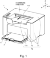
- Figure 1 shows a perspective view of the image forming apparatus 1
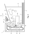
- Figure 2 is a view for illustrating an interval structure of the image forming apparatus 1 as viewed from the X direction (rotational axis direction of the photosensitive drum 411).
- Figure 2 principally shows members relating to an image forming process.
- the image forming apparatus 1 includes a feeding tray 4 in which recording materials P are accommodated and a discharging tray 114 on which discharged recording materials P are stacked.
- the feeding tray 4 is capable of being pulled out in the Y direction, and a user is capable of supplying (replenishing) the recording materials P to the feeding tray 4.
- the recording materials P which are fed from the feeding tray 4 and on which images are formed are discharged from a discharge opening 115 toward a discharging direction (Y direction) indicated in Figure 1 , and are stacked on the discharging tray 114.
- a front cover 70 is provided at a part of an end surface (part of a front surface) of the image forming apparatus 1 on a downstream side of the discharging direction.
- a side surface or a top surface of the image forming apparatus 1 which is a part of the front surface other than a place where the front cover 70 is provided with an outer casing cover 71.
- the front cover 70, the outer casing cover 71, and the above-described discharging tray 114 form together a casing 72 of the image forming apparatus 1.
- the casing 72 is a member covering entirety of the image forming apparatus 1 and includes a process member such as a scanner unit 50 described later inside thereof.
- the above-described discharge opening 115 is an opening formed at a part of the casing 72, and the recording material P passes through this opening and is discharged to an outside of the image forming apparatus 1.
- the image forming apparatus 1 includes an image forming portion 400 including a photosensitive unit 401 provided with the photosensitive drum 411 and a charging roller (charging member) 417 and a developing unit 402 provided with a developing roller 412 and an accommodating portion 418.
- the photosensitive drum 411 is an image bearing member for bearing an electrostatic latent image.
- the developing roller 412 is a developer carrying member for carrying toner as a developer.
- the scanner unit 50 irradiate the photosensitive drum 411 with laser light on the basis of inputted image information.
- the scanner unit 50 includes a laser oscillator, a polygon mirror and lenses for irradiating the photosensitive drum 411 with the laser light, a scanner motor for rotating the polygon mirror, and a frame for supporting these members.
- the photosensitive drum 411 is electrically charged in advance by the charging roller 417, and the electrostatic latent image is formed on the photosensitive drum 411 by irradiating the photosensitive drum 411 with the laser light. Thereafter, the toner accommodated in the accommodating portion 418 is carried to the photosensitive drum 411 by the developing roller 412, whereby this electrostatic latent image is developed and a toner image is formed on the photosensitive drum 411.
- the recording material P is fed from the feeding tray 4.
- a pick-up roller 3 On a feeding passage of the image forming apparatus 1, a pick-up roller 3, a feeding roller 5a, and a conveying roller pair 5c are provided.
- the pick-up roller 3 contacts an uppermost one of the recording materials P accommodated in the feeding tray 4 and feeds the recording material P by rotation of the roller itself.
- the feeding roller 5a and a separation roller 5b press-contacted thereto form a separation nip.
- the feeding roller 5a and the separation roller 5b separates the plurality of recording materials P and feed only the recording material P positioned in an uppermost position toward a downstream side.
- the recording material P fed from the feeding tray 4 is conveyed toward a transfer roller 7 by the conveying roller pair 5c.
- a transfer bias is applied, so that the toner image formed on the photosensitive drum 411 is transferred onto the recording material P.
- the recording material P on which the toner image is transferred by the transfer roller 7 is subjected to a heating and pressing processing by a fixing device 9, so that the toner image is fixed on the recording material P.
- the fixing device 9 is constituted by a heating roller 9a in which a fixing heater 9c is incorporated and a pressing roller 9b urged toward the heating roller 9a. Further, the recording material P on which the toner image is fixed is discharged onto the discharging tray 114 by a discharging roller pair 310.
- the discharging roller pair 310 subjects the recording material P on which first side the image is formed to switch-back, and thus guide the recording material P to a double-side feeding passage 16.
- the recording material P guided to the double-side feeding passage 16 is conveyed again toward the transfer 7 by a double-side conveying roller pair 5d.
- the recording material P is, after the image is formed on a second side, discharged onto the discharging tray 114 by the discharging roller pair 310.
- the toner remaining on the photosensitive drum 411 after the toner image is transferred onto the recording material P is removed by a cleaning unit 413.
- the image forming apparatus is provided with a CPU 399 as a controller.
- the image forming apparatus 1 is provided with the supplying portion 200 to which a user or a service person is capable of supplying the toner from an outside without demounting the accommodating portion 418 from the casing 72 in the case where a remaining toner amount in the accommodating portion 418 becomes small.
- a constitution in which a toner pack 10 described later is detachably mountable to the supplying portion 200 is employed.
- the image forming apparatus 1 in this embodiment is capable of supplying the toner to the accommodating portion 418 through the supplying portion 200 without removing the image forming portion 400 from the casing 72.
- Figure 3 is a side view of the image forming apparatus 1 for illustrating arrangement of the supplying portion 200.
- Figure 3 is a left-hand side view of the image forming apparatus 1 when viewed along a rotational axis direction of the photosensitive drum 11.
- a part of the outer casing cover 71 is omitted, so that an inside of the image forming apparatus 1 is shown.
- the supplying portion 200 is provided with a mounting portion 210 on which the toner pack 10 (not shown in Figure 3 ) is mounted, a toner receiving portion 200, a supply path portion 403 connecting the accommodating portion 418 and the toner receiving portion 220.
- the mounting portion 210 is disposed on a top surface portion 340 described later and in which a mounting hole 210c in which the toner pack 10 is mounted is formed.
- the toner is moved from the toner pack 10 mounted in the mounting hole 210c to the toner receiving portion 220 and the supply path portion 403 in a named order, and is finally supplied to the accommodating portion 418.
- Figure 4 is a side view of the image forming apparatus 1 for illustrating the arrangement of the supplying portion 200.
- Figure 4 is a top (plan) view of the image forming apparatus 1 from which the outer casing cover 71 is removed.
- the mounting portion 210 the mounting hole 210c is formed.
- the mounting portion 210 is provided with a ring portion 210b disposed so as to surround the mounting hole 210c and a gripping portion 210a connected to the ring portion 210b.
- a width of the supplying portion 200 with respect to the X direction is shorter (narrower) than a width of the accommodating portion 418 with respect to the X direction.
- the supplying portion 200 is disposed while avoiding a laser irradiation region (lattice-like hatched portion in Figure 4 ) of the laser light emitted from the scanner unit 50.
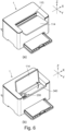
- Figure 5 includes enlarged perspective views of the supplying portion 200.
- Part (a) of Figure 5 is a view showing a state in which the gripping portion 210a is positioned in an initial position
- part (b) of Figure 5 is a view showing a state in which the gripping portion 210a is positioned in a supplying position.
- a receiving opening 220c connected to the supply path portion 403 is formed on an inner wall of the toner receiving portion 220 having a cylindrical shape.
- the toner passes from the toner receiving portion 220 through this receiving opening 200c and is guided to the supply path portion 403, and thereafter, passes through the supply path portion 403 and is accommodated in the accommodating portion 418.
- the receiving opening 220c formed in the toner receiving portion 220 is closed by a receiving portion shutter 230, and is not actually seen, and therefore, is indicated by a dotted line.
- the receiving portion shutter 230 is a cylindrical-shaped member concentric with the toner receiving portion 220 and is provided inside the toner receiving portion 220.
- a shutter opening 230c for permitting passing of the toner is formed, but is not actually seen, and therefore, is indicated by a dotted line.
- a receiving seal 241 is disposed at a periphery of the shutter opening 230c.
- the receiving opening 220c and the shutter opening 230c are in deviated positions, and therefore, the receiving opening 220c is blocked.
- a constitution in which even in the case where the mounting portion 210 is rotated in a state in which the toner pack 10 is not mounted, the receiving portion shutter 230 is prevented from rotating is employed.
- an engaging projection 210d of the mounting portion 210 and a transmitting portion 230g of the receiving portion shutter 230 engage with a shutter member 11 for the toner pack 10 described later.
- the user grips of the gripping portion 210a and rotates the gripping portion 210a by about 90° from a state of part (a) of Figure 5 to a state of the part (b) of Figure 5 , so that the receiving portion shutter 230 can be rotated inside the toner receiving portion 220.
- the receiving opening 220c and the shutter opening 230c are in overlapping positions, and therefore, the receiving opening 220c is opened and is in a state in which the toner can be supplied through the receiving opening 220c.
- the toner is stirred in the accommodating portion 418 by an unshown stirring member, so that there is a need to block the receiving opening 220c so that the toner does not leak out through the receiving opening 220c. Accordingly, during image formation, the gripping portion 210a is moved to a position shown in part (a) of Figure 5 . This position is called an initial position of the gripping portion 210a.
- the gripping portion 210a is moved to a position shown in part (b) of Figure 5 . This position is called a supplying position of the gripping portion 210a.
- the image forming apparatus 1 is provided with a lever position detecting sensor 224.
- the mounting portion 210 is provided with a portion-to-be-detected 210e contacting the lever position sensor 224.
- the portion-to-be-detected contacts the lever position sensor 224.
- the portion-to-be-detected 210e is separated from the lever position sensor 224.
- the toner receiving portion 220 is provided with a base supporting portion 220e engaging with a circumferential groove portion 11g of a shutter member 11 described later.
- the base supporting portion 220e engages with the circumferential groove portion 11g is a process in which the gripping portion 210a is moved from the initial position to the supplying position, and thus restricts removal of the toner pack 10.
- Figure 6 shows perspective views of the image forming apparatus 1.
- Part (a) of Figure 6 is the perspective view of the image forming apparatus 1 in a state in which the discharging tray 114 is closed.
- Part (b) of Figure 6 is the perspective view of the image forming apparatus 1 in a state in which the discharging tray 114 is open.
- Figure 7 shows perspective views of the image forming apparatus 1.
- Part (a) of Figure 7 is the perspective view of the image forming apparatus 1 in which the gripping portion 210a is in the initial position.
- Part (b) of Figure 7 is the perspective view of the image forming apparatus 1 in which the toner pack 10 is mounted and the gripping portion 210a is in the supplying position.
- the supplying portion 200 is provided at the top surface portion 340 of an upper portion of the front surface of a main assembly of the image forming apparatus 1.
- the discharging tray 114 is configured to be movable between a position where the supplying portion 200 is covered and a position where the supplying portion 220 is exposed.
- the discharging tray 114 has a constitution in which the discharging tray 114 covers the supplying portion 200 and is movable between a position where the recording materials P discharged from the discharge opening 115 are capable of being stacked (part (a) of Figure 6 ) and a position where the supplying portion 200 is exposed (part (b) of Figure 6 ).
- the supplying portion 200 is provided at the upper portion of the front surface of the main assembly of the image forming apparatus 1, and therefore, the user is easy to access the supplying portion 200 also during the supply.
- the recording materials P stacked on the discharging tray 114 is removed, and the discharging tray 114 is opened and is moved to the position shown in part (b) of Figure 6 .
- the discharging tray 114 is opened, the supplying portion 200, the top surface portion 340 provided adjacent to the supplying portion 200, and the mounting portion 210 positioned on the top surface portion 340 are exposed. Then, the toner pack 10 is inserted into the exposed supplying portion 200.
- an image forming system 1A the whole of the image forming apparatus 1 and the toner pack 10 is called an image forming system 1A.
- Part (a) of Figure 7 shows a state in which the toner pack 10 is inserted into the supplying portion 200.
- Part (b) of Figure 7 shows a state in which the gripping portion 210a is moved from the initial position to the supplying position.
- the toner pack 10 is inserted into the supplying portion 200 and the gripping portion 210a is moved from the initial position to the supplying position, so that a state in which supply of the toner from the toner pack 10 is possible is formed. In that state, the toner is discharged from the toner pack 10 and is supplied to the accommodating portion 418.
- the gripping portion 210a is returned to an original position.
- the receiving portion shutter 230 of the supplying portion 200 and the shutter member 11 of the toner pack 10 rotate together.
- the receiving portion shutter 230 covers the receiving opening 220c and the shutter member 11 covers a discharge opening 13a of the toner pack 10 described later.
- lock between the supplying portion 200 and the toner pack 10 (engagement between the circumferential groove portion 11g and the base supporting portion 220e) is released (disengaged), so that removal of the toner pack 10 from the supplying portion 200 becomes possible.
- a constitution of the toner pack (toner supply container, toner supply cartridge) 10 will be described.
- Figure 8 includes perspective views of the toner pack 10 according to this embodiment.
- Part (a) of Figure 8 is the perspective view of the toner pack 10 in an assembled state.
- Part (b) of Figure 8 is the perspective view of the toner pack 10 in a disassembled state.
- the toner pack 10 includes the shutter member 11, a seal member 12, a supply base 13, a memory tag 14, an expansion member 15, and a pouch 16.
- the pouch (bag) 16 as a container portion (container) for accommodating the toner is a flexible container. Inside the pouch 16, an accommodating portion (space) 16a for accommodating the toner is formed.
- the pouch 16 includes one end portion (first end portion) 16b and the other end portion (second end portion) 16c on a side opposite from the one end portion 16b. At the one end portion 16b, an opening 16a for permitting discharge of the toner from the accommodating portion 16d is formed.
- a first direction is parallel to a direction of a rotational axis z of the shutter member 11 described later.
- a longitudinal direction of the toner pack 10 is a direction parallel to the first direction. That is, a length of the toner pack 10 is longer as a length with respect to the first direction than a length thereof with respect to a direction perpendicular to the first direction.
- the accommodating portion 16d includes a first accommodating portion 16d1 and a second accommodating portion 16d2 connected to the first accommodating portion 16d1.
- the first accommodating portion 16d1 has a shape narrowing toward the opening portion 16a and is formed so that the toner is easy to move toward the opening portion 16a.
- the pouch 16 can be deformed so as to compress the accommodating portion 16d form an outside toward an inside of the pouch 16, and by this, discharge of the toner T is promoted.
- the pouch 16 can be deformed toward the direction perpendicular to the first direction so that opposing walls (part of a sheet portion 16e described later) contact each other.
- a force for discharging the toner by deforming the pouch 16 may preferably be small.
- the toner pack 10 assumes the same attitude as an attitude when the toner pack 10 is mounted in the image forming apparatus 1 and is used, and the pouch 16 is deformed as described above in a state in which the toner is capable of being discharged from the discharge opening 13a described later, so that the toner can be discharged.
- the pouch 16 may preferably be constituted so that the opposing walls contact each other via the accommodating portion 16d when a force of 40N or less acts in a direction perpendicular to the rotational axis z at least at a part of the accommodating portion 16d.
- the pouch 16 is constituted so that the opposing walls contact each other via the accommodating portion 16d when a force of 10N or less (more preferably 5N or less) acts in the direction perpendicular to the rotational axis z at least at a part of the accommodating portion 16d.
- the pouch 16 includes the sheet portion 16e for forming the accommodating portion 16d.
- a thickness of the sheet portion 16e may preferably be 500 ⁇ m or less (more preferably 200 ⁇ m or less).
- the sheet portion 16e is a sheet made of polypropylene having a thickness of 100 ⁇ m or less.
- the pouch 16 is formed in a bag shape by subjecting the sheet portion 16e to thermal welding or the like.
- a form of the pouch 16 is not limited to this, and a material of the sheet portion 16e may be polyethylene, polyethylene terephthalate, or the like.
- the pouch 16 includes an overlapping portion 16f formed by casing parts of the sheet portion 16e to overlap with each other.
- the overlapping portion 16f is formed by subjecting the sheet 16e to thermal welding.
- the overlapping portion 16f includes a side (surface) overlapping portion 16f1 disposed on a side surface of the pouch 16.
- the pouch 16 may be formed by folding a single sheet portion 16e or may be formed by a plurality of sheets 16e.
- a size of the other end portion 16c of the pouch 16 is larger than a size of a tip (end) portion of a substrate installation portion 131 described later.
- the pouch 16 is reinforced by the overlapping portion 16f.
- the side overlapping portion 16f1 extends in the first direction.
- the expansion member 15 is a resin member formed in a substantially hexagonal shape at an outer peripheral surface and is connected to the opening portion 16a of the pouch 16. By this, even the flexible pouch 16 can maintain a state in which the opening portion 16a is open, by the expansion member 15.
- the expansion member 15 has an annular shape such that a hole through which the toner passes is formed.
- the expansion member 15 is fixed to the supply base 13 so that the opening portion 16a and the discharge opening 13a communicate with each other as described later.
- a connecting method between the expansion member 16 and the pouch 16 may be any method, and for example, it is possible to use a connecting method using various adhesives such as a hot melt, a connecting method in which the pouch 16 is thermally welded to the expansion member 15, and the like.
- the shape of the outer peripheral surface of the expansion member 15 may preferably be a shape such that the expansion member 15 is liable to slip when the user grips the expansion member 15 and may preferably be a polygonal shape.
- a structure of the outer peripheral surface of the expansion member 15 has a substantially hexagonal shape. By this, the opening portion 16a of the pouch 16 is also deformed along the outer peripheral surface of the expansion member 15 and is a hexagon in shape.
- the supply base 13 (discharging portion, discharging member, toner guiding portion, container receiving portion) 13 is disposed on an end side of the pouch 16.
- the supply base 13 has a function as a portion-to-be-inserted (portion-to-be-supported, portion-to-be-mounted) inserted into and supported by the image forming apparatus when the toner pack 10 is mounted to the image forming apparatus 1.
- the supply base 13 is mounted to the one end portion of the pouch 16 via the expansion member 15.
- the expansion member 15 and the supply base 13 can also be integrally formed. That is, the supply base 13 is caused to have a function of the expansion member 15, and may be directly connected to the pouch 16.
- the shutter unit 102 including the shutter member 11 is mounted.
- the shutter member 11 is a resin component which is formed so as to cover an outer periphery of the supply base 13 and which has a substantially cylindrical shape, and is supported by the supply base 13 in a rotatable state at a predetermined phase.
- a rotational axis of the shutter member 11 relative to the supply base 13 is a rotational axis (first axis) z.
- the rotational axis z extends in the first direction.
- the supply base 13 is provided with the toner discharge opening (discharge opening) 13a which is a through hole for permitting discharge of the toner accommodated in the pouch 16 and with the substrate installation portion (projected portion) 131 to which the memory tag 14 is mounted.
- the toner path 13c (described later) which is disposed between the pouch 16 and the discharge opening 13a and which is for permitting passing of the toner is formed.
- the substrate installation portion 131 is positioned at the top portion of the toner pack 10 with respect to the direction (first direction) parallel to the rotational axis z.
- the memory tag 14 is fixed in a position where the memory tag 14 overlaps with the rotational axis z.
- the substrate installation portion 131 projects toward a direction of the rotational axis z.
- the shutter member 11 is provided with a crossing wall 11w which extends in a direction crossing the direction of the rotational axis z and which includes a crossing wall 11w provided with a through hole 11w1.
- the through hole 11w1 exposes an electroconductive portion 14a to an outside of the toner pack 10.
- the substrate installation portion 131 is inserted into the through hole 11w1, so that the electroconductive portion 14a is exposed to the outside of the toner pack 10.
- the memory tag 14 is fixed to the substrate installation portion 131 with use of a means such as a double-side tape or an adhesive.
- a means such as a double-side tape or an adhesive.
- press-fitting or snap-fitting may also be used as a method for mounting the memory tag 14 on the substrate installation portion 131.
- the memory tag 14 includes the electroconductive portion 14a which is an electric contact (see Figure 11 ).
- the electroconductive portion 14a of the memory tag 14 is disposed so as to be exposed to the outside of the toner pack 10 with respect to a direction parallel to the rotational axis z.
- the seal member 12 is mounted to the shutter member 11.
- the seal member 12 is positioned in a region between the supply base and the shutter member 11 with respect to a radial direction relative to the rotational axis z, and is applied and fixed to an inner peripheral surface of the shutter member 11 with use of an unshown double-side tape.
- the toner pack 10 in this embodiment is capable of promoting discharge of the toner from the toner pack 10 by deforming the pouch 16.
- the pouch 16 may preferably employ a flexible structure (low-rigidity structure).
- the supply base 13 may preferably employ a structure higher in rigidity than the pouch 16. That is, when a force with the same magnitude acts on an object, deformation of the pouch 16 is larger than deformation of the supply base 13.
- the electroconductive portion 14a of the memory tag 14 When the electroconductive portion 14a of the memory tag 14 is positioned by the pouch 16 lower in rigidity than the supply base 13, the position of the electroconductive portion 14a of the memory tag 14 is liable to be deviated. In this embodiment, the electroconductive portion 14a of the memory tag 14 is positioned by the supply base 13, whereby the position of the electroconductive portion 14a of the memory tag 14 is not readily deviated. As a result, for example, the electroconductive portion 14a of the memory tag 14 can be positioned relative to the image forming apparatus 1 with accuracy.
- the supply base 13, the memory tag 14, the expansion member 15, and the pouch 16 which are integrally connected are referred to as a supply unit 101
- the shutter member 11 and the seal member 12 are referred to as the shutter unit 102. That is, the toner pack 10 includes the supply unit 101 and the shutter unit 102.
- the supply base 13 and the shutter unit 102 are disposed on the one end portion side of the toner pack 10, and the pouch 16 is disposed on the other end portion side of the toner pack 10.
- the shutter unit 102 includes the seal member 12 for sealing between the shutter member 11 and the supply base 13.
- a seal member provided with a hole through which the toner passes, so that the seal member seals between the shutter member 11 and the supply base 13, so that the seal member 12 can be omitted from the shutter unit 102.
- the shutter unit 102 does not include the seal member 12.
- a portion including the supply base 13, the memory tag 14, and the shutter unit 102 can be called a mounting unit detachably mountable to the image forming apparatus 1.
- the mounting unit is mountable to the pouch 16.
- the pouch 16 and the mounting unit are connected to each other via the expansion member 15.
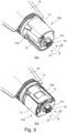
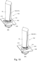
- Figure 9 includes perspective views of the toner pack 10, in which part (a) of Figure 9 shows a state in which the shutter unit 102 is in a closed position where the shutter unit 102 seals the discharge opening 13a, and part (b) of Figure 9 shows a state in which the shutter unit 102 is in a retracted position.
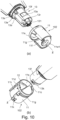
- Figure 10 (part (a) of Figure 10 , part (b) of Figure 10 ) includes perspective views for illustrating the structures of the shutter unit 102 and the supply base 13.
- the shutter unit 102 is rotatable around the rotational axis z with the rotational axis z as a center relative to the supply unit 101. That is the rotational axis of the shutter member 11 and the seal member 12 is the rotational axis z.
- the shutter unit 102 covers the discharge opening 13a and is configured to be movable between a closed position (cover position, first position) where discharge of the toner is restricted and a retracted position (second position, electroconductive portion position) retracted from the closed position.
- a closed position cover position, first position
- second position electroconductive portion position
- the discharge opening 13a is exposed toward the outside of the toner pack 10, so that discharge of the toner from the discharge opening 13a is permitted.
- the second position can also be called an open position where the discharge opening 13a is opened.
- z1 direction is a movement direction in which the shutter unit 102 moves from the first position to the second position
- z2 direction is a movement direction in which the shutter unit 102 moves from the second position to the first position
- a rotation angle (a difference between the first position and the second position) of the shutter unit 102 around the rotation axis z can be made 180 degrees or less.
- the rotation angle of the shutter unit 102 around the rotation axis z can be made 45 degrees or more. In this embodiment, the rotation angle of the shutter unit 102 is about 90 degrees.
- the discharge opening 13a opens toward a direction (preferably a direction perpendicular to the first direction) crossing the first direction.
- the discharge opening 13a is disposed toward the direction (preferably the direction perpendicular to the first direction) crossing the first direction.
- the supply base 13 is provided with the above-described discharge opening 13a, the substrate installation portion 131, and in addition, an outer peripheral portion 13f, a main assembly-engaging portion 13e, a shaft portion 13r, a flange portion 13s, and a claw portion (shutter restricting portion) 13k.
- the outer peripheral portion 13f (second surface, opening-forming portion, opening-forming wall) 13f is provided with the discharge opening 13a.
- the surface of the outer peripheral portion 13f faces toward the direction (preferably the direction perpendicular to the first direction) crossing the first direction. That is, a direction normal to the outer peripheral portion 13f is the direction (preferably the direction perpendicular to the first direction) crossing the first direction.
- the outer peripheral portion 13f extends along the direction parallel to the first direction and has an arcuate surface (arcuate shape). That is, a generatrix direction of the arcuate surface is the direction parallel to the first direction. A center of the arcuate surface coincides with the rotational axis z.
- the main assembly-engaging portion 13e is a projection provided relative to the discharge opening 13a with a predetermined gap on a side surface rotated in the Z2 direction by about 90 degrees, and engages with a part of the image forming apparatus 1 when the toner pack 10 is mounted to the image forming apparatus 1.
- the shaft portion 13r has an arcuate surface (arcuate shape) smaller in radius than the outer peripheral portion 13f.
- the flange portion 13s has an arcuate surface (arcuate shape) larger in radius than the outer peripheral portion 13f.
- a center of the arcuate surface of the shaft portion 13r and a center of the arcuate surface of the flange portion 13s coincide with the rotational axis z.
- Generatrix directions of these arcuate surfaces are also directions parallel to the first direction.
- the claw portion 13k has flexibility so as to be movable in a radial direction of a circle with the rotational axis z as a center.
- a tip (end) portion of the claw portion 13k is movable between a position outside the outer peripheral surface 13f and a position inside the outer peripheral surface 13f in the radial direction of the circle with the rotational axis z as the center.
- the shutter member 11 is a resin member having a substantially cylindrical shape.
- the shutter member 11 is provided with the through hole 11w1 and a bearing portion 11s. Further, on the shutter member 11, a locking claw 11c and a locking claw 11d, an exposure portion 11f, a circumferential groove portion 11g, a locking groove (shutter(-side) portion-to-be-restricted) 11k, and an outer periphery recessed portion 11h are formed.
- the through hole 11w1 and the bearing portion 11s engage with the shaft portion 13r and the flange portion 13s which are provided on the supply base 13.
- the shutter member 11 and the shutter unit 102 including the seal member 12 become rotatable around the supply base 13 relative to the rotational axis z.
- the locking claw 11c and the locking claw 11d engage with the flange portion 13s, and restrict movement of the shutter member 11 in the first direction relative to the supply base 13.
- the exposure portion 11f, the circumferential groove portion 11g, and the outer periphery recessed portion 11h are formed at an outer peripheral portion of the shutter member 11.
- the exposure portion 11f has a rectangular shape, and exposes the discharge opening 13 to the outside of the toner pack 10 when the shutter unit 102 is in the second position.
- the circumferential groove portion 11g is a groove extending in the direction crossing a direction of the rotational axis z.
- the circumferential groove portion 11g extends toward a circumferential direction (rotational direction of the shutter member 11) of the shutter member 11, and is formed in a part of a region (about 90°) of the shutter member 11.
- One end of the circumferential groove portion 11g is connected to the exposure portion 11f.
- the outer periphery recessed portion 11h is provided on a side opposite from the exposure portion 11f with respect to the circumferential direction of the shutter member 11 while sandwiching the rotational axis z.
- the outer peripheral recessed portion 11h is a surface recessed toward an inside of the shutter member 11 than the outer periphery of the shutter member 11 with respect to the radial direction of the circle with the rotation axis z as the center.
- the locking groove 11k is provided in a position where the claw portion 13k of the supply base 13 engages with the locking groove 11k when the shutter unit 102 is in the first position.
- the claw portion 13k and the locking groove 11k engage with each other, so that rotation of the shutter unit 102 is restricted. By this, leakage of the toner due to unintended movement of the shutter unit 102 to the second position by the user is prevented.
- the shutter unit 102 is rotated, the shutter unit 102 is displaced in a direction approaching the rotational axis z by applying an external force to the claw portion 13k, so that engagement between the claw portion 13k and the locking groove 11k is released.
- the seal member 12 is a sheet-like member which is constituted by a material such as an elastically deformable urethane foam or nonwoven cloth and which has a predetermined thickness. A surface of the seal member 12 on the shutter member 11 side is fixed to the inner peripheral surface of the shutter member 11 by a double-side tape or the like. By this, the seal member 12 is rotatable integrally with the shutter member 11.
- the seal member (sealing portion) 12 is pressed to the outside and is deformed by the outer peripheral portion 13f in a direction approaching the shutter member 11, i.e., a radial direction perpendicular to a direction of the rotational axis z in a state in which the shutter member 11 is assembled with the supply base 13. That is, the seal member 12 is in a state in which the seal member 12 is pressed against the outer peripheral portion 13f by a predetermined pressure. By this, the seal member12 is compressed between the outer peripheral portion 13f and the shutter member 11, so that toner leakage from a boundary between the seal member 12 and the outer peripheral portion 13f of the supply base 13 can be suppressed.
- the seal member 12 (of the seal member 12, a surface opposing the discharge opening 13a) is an opposing portion opposing the discharge opening 13a when the shutter unit 102 is in the first position.
- a constitution of the opposing portion of the shutter unit 102 is not limited to the above-described constitution.
- a constitution in which when the shutter unit 102 is in the first position, a part of the shutter member 11 opposes the discharge opening 13a may be employed. In that case, the part of the shutter member 11 has a function as the opposing portion.
- Figure 11 is an illustration of the memory unit.
- the memory tag 14 as the memory unit in this embodiment includes a memory (storing element) 14d for storing information on the toner pack 10 and an electroconductive portion (electrode portion, interface portion) 14a electrically connected to the memory 14d, and is constituted as an example of a memory portion.
- the electroconductive portion 14a includes a first electrode (first terminal, first memory electrode) 14a1 and a second electrode (second terminal, second memory electrode) 14a2, and the first electrode 14a1 and the second electrode 14a2 are electrically connected to the memory 14d.
- the memory tag 14 is provided with a holding portion (holding substrate) 14b for holding the electroconductive portions 14a (first electrode 14a1, second electrode 14a2).
- the memory tag 14 is provided with a protective portion 14c for protecting the memory 14d by covering the memory 14d.
- the electroconductive portion 14a is disposed on one surface (front surface) of the holding portion 14b, and the memory 14d is disposed on the other surface (back surface) of the holding portion 14b.
- the first electrode 14a1 has a first exposed surface 14a11 exposed to the outside of the toner pack 10.
- the second electrode 14a2 has a second exposed surface 14a21 exposed to the outside of the toner pack 10.
- the memory tag 14 in this embodiment is a plate-like member of 5.5 mm x 5 mm in area and 1.4 mm in thickness.
- the holding portion 14b and the protective portion 14c are integrated with each other.
- the memory tag 14 has a two-layer structure formed by the holding portion 14b and the protective portion 14c.
- the holding portion 14b and the protective portion 14c can be said as being a part of a substrate portion (substrate) provided with the electroconductive portion 14a.
- information on the toner pack is stored.
- information on a lot of the toner pack 10 and information on an amount and a characteristic of the toner accommodated in the toner pack 10 are included.
- information on the image forming apparatus 1 to which the toner pack 10 is mounted is stored in some cases.
- information used for control of the image forming apparatus 1 by a controller 399 is included.
- the controller 399 for the image forming apparatus 1 is electrically connected to the memory 14d through the electroconductive portion 14a, so that the controller 399 reads the information stored in the memory 14d and controls the image forming apparatus 1.
- the number of electrodes disposed in the electroconductive portion 14a is two, but the present invention is not limited thereto.
- the electroconductive portion 14a may include three or more electrodes. Further, one electrode is disposed in the holding portion, and another electrode may be disposed in another portion.
- Figure 12 includes perspective views showing a tip (end) portion of the toner pack 10.
- Part (a) of Figure 12 is the perspective view of the tip portion of the toner pack 10 with which the memory tag 14 is assembled.
- Part (b) of Figure 12 is the perspective view of the tip portion of the toner pack 10 before the memory tag 14 is assembled with the toner pack 10.
- Figure 13 includes perspective views for illustrating the arrangement of the memory unit in this embodiment.
- Part (a) of Figure 13 is a bottom view of the toner pack 10.
- Part (b) of Figure 13 is in an enlarged view of the memory tag 14.
- Figure 14 includes views for illustrating the arrangement of the memory unit in this embodiment.
- Part (a) of Figure 14 is a side view of the toner pack 10.
- Part (b) of Figure 14 is a sectional view of the toner pack 10.
- the substrate installation portion 131 is provided at a tip of the toner pack 10 in a direction of the rotational axis z. Further, as shown in part (b) of Figure 12 , the substrate installation portion 131 is provided with an installation surface (installation portion, positioning surface, positioning portion) on which the memory tag 14 is adhesively fixed.
- the installation surface 131a positions the electroconductive portions 14a (first electrode 14a1, second electrode 14a2) via a substrate including the protective portion 14c and the holding portion 14b. That is, the substrate of the memory tag 14 is fixed on the installation surface 131a and is positioned by the installation surface 131a, whereby the electroconductive portion 14a is positioned relative to the supply base 13. In this embodiment, the installation surface 131a positions the electroconductive portion 14a with respect to the first direction and a direction perpendicular to the first direction.
- the first exposed surface 14a11 of the first electrode 14a1 is disposed along a direction (preferably a direction perpendicular to) crossing the first direction.
- the first exposed surface 14a11 of the first electrode 14a1 is disposed on a flat plane (imaginary flat plane) extending along the direction (preferably the direction perpendicular to) crossing the first direction.
- the first exposed surface 14a11 faces the first direction. That is, a normal direction to the first exposed surface 14a11 crosses (preferably be perpendicular to) the direction perpendicular to the first direction.
- the first exposed surface 14a11 is exposed to the outside of the toner pack 10.
- the supply base 13 and the pouch 16 are disposed. Further, the first exposed surface 14a11 extends in the direction (preferably the direction perpendicular to) crossing the first direction, while the outer peripheral portion 13f of the supply base 13 extends in the direction crossing (preferably be perpendicular to) a direction in which the first exposed surface 14a11 extends.
- the second exposed surface 14a21 of the second electrode 14a2 is disposed along a direction (preferably a direction perpendicular to) crossing the first direction.
- the second exposed surface 14a21 of the second electrode 14a2 is disposed on a flat plane (imaginary flat plane) extending along the direction (preferably the direction perpendicular to) crossing the first direction.
- the second exposed surface 14a21 faces the first direction. That is, a normal direction to the second exposed surface 14a21 crosses (preferably be perpendicular to) the direction perpendicular to the first direction.
- the second exposed surface 14a21 is exposed to the outside of the toner pack 10.
- the supply base 13 and the pouch 16 are disposed.
- the outer peripheral portion 13f of the supply base 13 extends in the direction crossing (preferably be perpendicular to) a direction in which the second exposed surface 14a21 extends.
- the second exposed surface 14a21 and the first exposed surface 14a11 are disposed on the same flat plane. However, with respect to the first direction, a position of the second exposed surface 14a21 and a position of the first exposed surface 14a11 may be different from each other.
- a most tip end portion 131b as a projected portion projecting more than the first exposed surface 14a11 and the second exposed surface 14a21 is provided.
- the installation surface 131a is positioned inside the most tip end portion 131b of the substrate installation portion 131 with respect to the first direction.
- a distance from the most tip end portion 131b to the installation surface 131a is longer than 1.4 mm which is a thickness (equal to a thickness of the substrate) of the memory tag 14.
- the substrate installation portion 131 includes a projected wall 131c extending in a direction crossing the first direction.
- a plurality of projected walls 131c are provided while sandwiching the memory tag 14.
- the projected wall 131c has a function as a connector positioning portion (apparatus-side contact point positioning portion) which engages with a connector 250 described later and which is for positioning the connector 250.
- Part (a) of Figure 13 is a view in which the toner pack 10 is viewed along the direction (first direction) of the rotational axis z.
- the first exposed surface 14a11 and the second exposed surface 14a21 are disposed inside a first imaginary circle L1 passing through an outer end (outermost portion) of the shutter unit 102 with the rotational axis z as the center.
- the outer end of the shutter unit 102 refers to a portion most away from the rotational axis z with respect to the direction perpendicular to the rotational axis z.
- the outer end of the shutter unit 102 coincides with an outer end (portion most away from the rotational axis z) of the shutter member 11.
- the whole of the shutter unit 102 is positioned inside the imaginary circle L1.
- the first electroconductive portion surface 14a11 and the second exposed surface 14a21 are positioned inside a second imaginary circle L2 passing through an opposing portion opposing the discharge opening 13a with the rotational axis z as the center.
- the opposing portion is a surface (surface contacting a periphery (outer peripheral portion) of the discharge opening 13a) opposing the discharge opening 13a of surfaces of the seal member 12.
- the first exposed surface 14a11 and the second exposed surface 12a21 are disposed inside a third imaginary circle L3 passing through an inner end (innermost portion) of the shutter unit 102 with the rotational axis z as the center.
- the inner end of the shutter unit 102 refers to a portion closest to the rotational axis z with respect to the direction perpendicular to the rotational axis z.
- the inner end of the shutter unit 102 coincides with an inner wall surface of the through hole 11w1 of the shutter member 11. That it, the inner end of the shutter unit 102 coincides with an inner end (portion closest to the rotational axis z) of the shutter member 11.
- the whole of the shutter unit 102 is positioned outside the imaginary circle L3.
- the first exposed surface 14a11 and the second exposed surface 14a21 can be disposed in a space-saving manner.
- the electroconductive portion 14a is disposed inside the first imaginary circle L1, the second imaginary circle L2, and the second imaginary circle L3.
- the holding portion 14b is disposed inside the first imaginary circle L1, the second imaginary circle L2, and the second imaginary circle L3.
- the whole of the memory tag 14 including the memory 14d is disposed inside the first imaginary circle L1, the second imaginary circle L2, and the second imaginary circle L3.
- Part (b) of Figure 13 is an enlarged view in the neighborhood of the memory tag 14. As viewed along the first direction, the rotational axis z is positioned between the first exposed surface 14a11 and the second exposed surface 14a21.
- the holding portion 14b of the memory tag 14 includes a first substrate end 14fx1 and a second substrate end 14fx2 opposite from the first substrate end 14fx1.
- the holding portion 14b of the memory tag 14 includes a third substrate end 14fy1 and a fourth substrate end 14fy2 opposite from the third substrate end 14fy1.
- the rotational axis z is positioned between the first substrate end 14fx1 and the second substrate end 14x2.
- the whole of the electroconductive portion 14a is positioned between the first substrate end 14fx1 and the second substrate end 14fx2.
- the rotational axis z is positioned between the third substrate end 14fy1 and the fourth substrate end 14fy2.
- the whole of the electroconductive portion 14a is positioned between the third substrate end 14fy1 and the fourth substrate end 14fy2.
- an outer configuration of the holding portion 14b coincides with an outer configuration of the protecting portion 14a.
- the electroconductive portion 14a of the memory tag 14 includes a first electroconductive portion end 14gx1 and a second electroconductive portion end 14gx2 opposite from the first electroconductive portion end 14gx1.
- the electroconductive portion 14a of the memory tag 14 includes a third electroconductive portion end 14gy1 and a fourth electroconductive portion end 14gy2 opposite from the third electroconductive portion end 14gy1.
- the first electroconductive portion end 14gx1, the second electroconductive portion end 14gx2, the third electroconductive portion end 14gy1, and the fourth electroconductive portion end 14gy2 coincide with at least either one of end portions of the first exposed surface 14a11 and the second exposed surface 14a21.
- the rotational axis z is positioned between the first electroconductive portion end 14gx1 and the second electroconductive portion end 14gx2.
- the whole of the electroconductive portion 14a is positioned between the first electroconductive portion end 14gx1 and the second electroconductive portion end 14gx2.
- the rotational axis z is positioned between the third electroconductive portion end 14gy1 and the fourth electroconductive portion end 14gy2.
- the whole of the electroconductive portion 14a is positioned between the third electroconductive portion end 14gy1 and the fourth electroconductive portion end 14gy2.
- the holding portion 14b and the electroconductive portion 14a of the memory tag 14 are disposed in the neighborhood of the rotational axis z of the shutter unit 102. Accordingly, the holding portion 14b and the electroconductive portion 14a of the memory tag 14 and the shutter unit 102 can be disposed in a space-saving manner.
- the shutter unit 102 is constituted so that the electroconductive portion 14a is exposed to the outside of the toner pack 10.
- the electroconductive portion 14a of the memory tag 14 is disposed at a portion close to the rotational axis z of the shutter unit 102, so that a degree of design freedom regarding the shape and the arrangement of the shutter unit 102 can be improved.
- Part (a) of Figure 14 is a side view of the toner pack 10 in which the toner pack 10 is viewed from above toward below in part (a) of Figure 13 .
- Part (b) of Figure 14 is a sectional view of the toner pack 10 in a line A-A along the rotational axis z of part (a) of Figure 14 .
- a fixing position of the memory tag 14 is in inside of a radius of rotation (radius of the imaginary circle L1) of the shutter member 11 projected in the first direction, illustrated by thick broken lines in Figure 13 .
- the radius of rotation of the shutter member 11 coincides with a radius of rotation of the shutter unit 102.
- the fixing position of the memory tag 14 is disposed inside also for a projection range W of the discharge opening 13a in the first direction as shown by thin broken lines in parts (a) and (b) of Figure 14 .
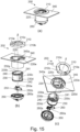
- Figure 15 includes views for illustrating the constitution of the supplying portion 200.
- Part (a) of Figure 15 is a partial perspective view of the supplying portion 200
- part (b) of Figure 15 and part (c) of Figure 15 are exploded perspective views in which the supplying portion 200 is viewed from directions different from each other, respectively.
- Figure 16 includes views for illustrating the constitution of the supplying portion 200.
- Part (a) of Figure 16 is a schematic view in which the supplying portion 200 is viewed from directly above the rotational axis z, part (b) of Figure 16 is a sectional view along A-A direction shown in part (a) of Figure 16 , and part (c) of Figure 16 is an exploded view of the supplying portion 200 in a cross section as viewed from a direction of part (b) of Figure 16 .
- the supplying portion 200 is disposed on the top surface portion 340 and is provided with the mounting portion 210, the toner receiving portion 220, a receiving portion shutter 230, a shutter seal 240, a receiving seal 241, the connector 250, a receiving bottom 260, and a bottom seal 242.
- the rotational axes shown in parts (a) to (c) of Figure 15 and parts (a) to (c) of Figure 16 are rotational axes of the receiving portion shutter 230 and the mounting portion 210 and coincide with the rotational axis z of the above-described shutter unit 102 in the state in which the toner pack 10 is mounted.
- the mounting portion 210 includes a gripping portion 210a operated by the user, a ring portion 210b engaging with the top surface portion 340, a mounting hole 210c in which the toner pack 10 is mounted, and an engaging projection 210d engaging with the shutter member 11.
- the top surface potion 340 is a part of the casing 72 and includes a guiding groove 340a.
- the toner receiving portion 220 includes a receiving opening 220c, a seal inner wall 220d, and a base supporting portion 220e.
- the receiving portion shutter 230 is a cylindrical component (part) and includes an inner peripheral portion 230a, a shutter engaging portion 230b, a shutter opening 230c, a flange portion 230d, a connecting hole 230e, and a claw releasing portion (restriction releasing portion) 230f. Further, to the receiving portion shutter 230, each of a shutter seal 240, a receiving seal 241, and a bottom seal 242 which are formed with a foam material such as an urethane foam is applied and fixed by a double-side tape.
- the connector 250 includes a connector electrode 250a contacting the electroconductive portion 14a of the memory tag 14, and an urging spring 250b.
- the connector electrode 250a and the urging spring 250b are springs made of metal and have flexibility with respect to a direction along the rotational axis z. Further, the connector electrode 250a is electrically connected to the controller 399 of the image forming apparatus 1 by an unshown signal line.
- the connector 250 is a holding member for holding the connector electrode 250a.
- the receiving bottom 260 includes a connector accommodating portion 260a and is fixed to the toner receiving portion 220.
- the mounting portion 210 is rotatable around the rotational axis z relative to the top surface portion 340 by being supported at the ring portion 210b by the guiding groove 340a provided in the top surface portion 340.
- the receiving portion shutter 230 is rotatable around the rotational axis z relative to the toner receiving portion 220 by being supported at the flange portion 230d by the toner receiving portion 220.
- the shutter seal 240 is provided at an outer periphery of the receiving portion shutter 230 and contacts the toner receiving portion 220, so that the shutter seal 240 closes a gap between the receiving portion shutter 230 and the toner receiving portion 220.
- the receiving seal 241 is provided so as to surround a periphery of the shutter opening 230c at the inner peripheral portion 230a of the receiving portion shutter 230 and contacts the seal inner wall 220d of the toner receiving portion 220.
- the bottom seal 242 is provided at a lower portion of the flange portion 230d and closes a gap between the receiving portion shutter 230 and the receiving bottom 260.
- the connector electrode 250a of the connector 250 is exposed toward above in the first direction. Further, at this time, the connector 250 is in a state in which the connector 250 is supported by the receiving bottom 260, and the urging spring 250b is in a compressed state. Accordingly, by a force of the urging spring 250b, the connector 250 is urged upward in the direction of the rotational axis z.
- the connector 250 engages with the projected wall 131d of the supply base 131, and is positioned with respect to the direction perpendicular to the first direction. That is, the projected wall 131 has a function as an electrode positioning portion for positioning the connector electrode 250a.
- Figure 17 (part (a) of Figure 17 , part (b) of Figure 17 ) includes perspective views for illustrating mounting of the toner pack 10.
- Part (a) of Figure 17 and part (b) of Figure 17 are the perspective views in which states before the toner pack 10 is inserted into the supplying portion 200 are viewed from different directions, respectively.
- the toner pack 10 is mounted into the supplying portion 200 so that the supply base 13 is positioned on a side downstream of the pouch 16 with respect to a mounting direction thereof into the supplying portion 200. That is, in this embodiment, the toner pack 10 is mounted so that the electroconductive portion 14a faces the downstream side in the mounting direction. Accordingly, the first exposed surface 14a11 and the second exposed surface 14a21 are disposed so as to face the downstream side of the mounting direction, and is exposed toward the downstream side of the mounting direction.
- the toner pack 10 is mounted to the supplying portion 200 along the rotational axis z. Further, in this embodiment, the toner pack 100 is mounted so that the direction of the rotational axis z becomes parallel to the vertical direction.
- the main assembly(-side) engaging portion 13e of the supply base 13 and the base supporting portion 220e of the toner receiving portion 220 engage with each other.
- rotation of the supply base 13, the expansion member 15, and the pouch 16 around the rotational axis z is restricted.
- the outer peripheral recessed portion 11h of the shutter member 11 engages with each of the engaging projection 210d of the mounting portion 210 and the shutter engaging portion 230b of the receiving portion shutter 230.
- the claw releasing portion 230f shown in part (a) of Figure 16 is provided in a position corresponding to the claw portion 13k. Accordingly, when the toner pack 10 is inserted into the supplying portion 200, the claw releasing portion 230f retracts the claw portion 13k toward the inside of the shutter member 11. By this, engagement between the claw portion 13k and the locking groove 11k is avoided, so that the shutter member 11 and the supply base 13 becomes rotatable relative to each other.
- the shutter unit 102 is rotatable integrally with the mounting portion 210 and the receiving portion shutter 230. That is, when the toner pack 10 is mounted to the supplying portion 200, the toner receiving portion 220, the supply base 13, the expansion member 15, and the pouch 16 become a state in which these members are fixed to each other (state in which these members are not moved relative to each other). In this state, when the mounting portion 210 is rotated, the shutter unit 102 and the receiving portion shutter 230 are rotated around the rotational axis z relative to the toner receiving portion 220, the supply base 13, the expansion member 15, and the pouch 16.
- Figure 18 includes illustrations of the supplying portion 200 to which the toner pack 10 is mounted.
- Part (a) of Figure 18 is a sectional view passing through the rotational axis z and a center of the discharge opening 13a.
- Part (b) of Figure 18 is a sectional view passing through the rotational axis z and perpendicular to part (a) of Figure 18 .
- the connecting hole 230e is a positioning portion for determining the position of the toner pack 10 relative to the image forming apparatus 1 with respect to the direction perpendicular to the direction of the rotational axis z.
- the shaft portion 13r is a portion-to-be-positioned which is positioned by the connecting hole 230e.
- the installation surface 131a is disposed at the tip portion of the shaft portion 13r.
- the electroconductive portion 14a of the memory tag 14 is disposed at the tip portion of the shaft portion 13r.
- the supply base 13 is provided with the toner path 13c connected at one end thereof to the discharge opening 13a.
- the other end of the toner path 13c is connected to the accommodating portion 16d (first accommodating portion 16d1) of the toner pack 16.
- the toner path 13c has a toner guiding surface (guiding surface) 13c1 inclined relative to the direction of the rotational axis z and opposing the discharge opening 13a.
- the toner supplied from the toner pack 16 to the toner path 13c is easy to move toward the discharge opening 13a by the toner guiding surface 13c1.
- a position of the toner guiding surface 13c1 overlaps with the position of the discharge opening 13a.
- the electroconductive portion 14a (first electrode 14a1, second electrode 14a2) overlaps with the toner path 13c and the toner guiding surface 13c1. More specifically, the first exposed surface 14a11 and the second exposed surface 14a21 overlap with the toner path 13c and the toner guiding surface 13c1. That is, the electroconductive portion 14a can be disposed in a space-saving manner while ensuring sizes of the toner path 13c and the toner guiding surface 13c1.
- a position of the toner path 13c and a position of the electroconductive portion 14a do not overlap with each other. That is, with respect to the first direction, the toner path 13c and the electroconductive portion 14a are disposed in different positions (deviated positions). Accordingly, with respect to the direction perpendicular to the first direction, it is possible to suppress upsizing of the supply base 13 while ensuring an arrangement space of the toner path 13c and an arrangement space of the electroconductive portion 14a.
- the discharge opening 13a is disposed inside the shutter unit 102, and the first exposed surface 14a11 and the second exposed surface 14a21 are disposed outside the shutter unit 102. Accordingly, it is possible to suppress deposition of the toner on the first exposed surface 14a11 and the second exposed surface 14a21.
- the crossing wall 11w of the shutter member 11 is positioned between the discharge opening 13a and the first exposed surface 14a11 with respect to the direction of the rotational axis z (first direction).
- the crossing wall 11w of the shutter member 11 is positioned between the discharge opening 13a and the second exposed surface 14a21 with respect to the direction of the rotational axis z.
- the crossing wall 11w is positioned between the electroconductive portion 14a of the memory tag 14 including the first exposed surface 14a11 and the second exposed surface 14a21, and the discharge opening 13a.
- the shutter unit 102 is in the first position, and the seal member 12 covers the discharge opening 13a.
- the crossing wall 11w partitions between the electroconductive portion 14a of the memory tag 14 including the first exposed surface 14a11 and the second exposed surface 14a21, and the discharge opening 13a.
- the memory tag 14 fixed to the top portion of the toner pack 10 contacts the connector 250.
- the connector 250 engages with the above-described projected wall 131c. By this, with respect to the direction crossing (preferably perpendicular to) the first direction, the connector 250 is positioned relative to the toner pack 10.
- the electroconductive portion 14a presses the connector electrode 250a into the direction along the rotational axis z.
- the connector electrode 250a contacts the electroconductive portion 14a at a predetermined pressure, so that the storing element of the memory tag 14 and the controller 399 of the image forming apparatus 1 are electrically connected to each other. More specifically, one connector electrode 250a contacts the first exposed surface 14a11, and the other connector electrode 250a contacts the second exposed surface 14a21.
- Figure 19 includes illustrations of the supply portion 200 to which the toner pack 10 is mounted. Part (a) of Figure 19 is the illustration before the mounting portion 210 is rotated. Part (b) of Figure 19 is the illustration after the mounting portion 210 is rotated.
- Discharge of the toner from the toner pack 10 toward the image forming apparatus 1 will be described.
- the user rotates the mounting portion 210 by about 90 degrees from a state in which the toner pack 10 is mounted to the supply portion 200 as shown in part (a) of Figure 19 , in z1 direction relative to the rotational axis z as shown in part (b) of Figure 19 .
- a length of the toner pack 10 with respect to the vertical direction in an attitude of the toner pack 10 mounted to the supply portion 200 is longer than a length of the toner pack 10 with respect to the horizontal direction.
- the mounting portion 210, the shutter unit 102, and the receiving portion shutter 230 are in an integrally rotatable state. Accordingly, by rotation of the mounting portion 210, the shutter unit 102 and the receiving portion shutter 230 are rotated integrally with the mounting portion 210. At this time, the pouch 16, the expansion member 15, and the supply base 13 are not moved (rotated) relative to the image forming apparatus 1. Further, when the shutter unit 102 and the receiving portion shutter 230 are rotated with the mounting portion 210, the toner receiving portion 220 is not moved (rotated).
- Figure 20 includes illustrations of operations of the shutter unit 102 and the receiving portion shutter 230.
- Part (a) of Figure 20 is the illustration in which the toner pack 10 mounted to the supply portion 200 is viewed from a side opposite from the discharge opening 13a along the direction perpendicular to the first direction.
- Parts (b) to (d) of Figure 20 are sectional views in which a cut surface of the toner pack 10 and the supply portion 200 along a chain line D-D shown in part (a) of Figure 20 is viewed from the tip (end) side of the toner pack 10.
- an outer configuration of the memory tag 14 and the electroconductive portion 14a is projected by a broken line.
- Part (b) of Figure 20 is a state immediately after the toner pack 10 is mounted to the supply portion 200, and at this time, the discharge opening 13a is closed by the seal member 12 compressed by the shutter member 11. Further, the shutter opening 230c of the receiving portion shutter 230 is closed by the seal inner wall 220d and the receiving seal 241.
- the shutter member 11, the seal member 12, the receiving portion shutter 230, and the receiving seal 241 are also integrally rotated.
- the discharge opening 13a of the toner pack 10 When the user further rotates the mounting portion 210, as shown in part (d) of Figure 20 , the discharge opening 13a of the toner pack 10, the shutter opening 230c of the receiving portion shutter 230, the shutter opening 230c of the receiving portion shutter 230, and the receiving opening 220c of the toner receiving portion 220 are in a communication state. Accordingly, the toner accommodated inside the pouch 16 can be discharged from the receiving opening to the accommodating portion 418 positioned inside the image forming apparatus 1.
- Figure 21 includes illustrations regarding a constitution for restricting before the shutter unit 102 is rotated.
- Part (b) of Figure 21 is the illustration during the rotation of the shutter unit 102.
- Part (c) of Figure 21 is the illustration after the shutter unit 102 is rotated.
- Figure 21 includes the illustration showing the toner pack 10 in a state in which the toner pack 10 is mounted to the supply portion 200. In Figure 21 , a part of the components is omitted.
- the base supporting portion 220 of the toner receiving portion 220 enters the circumferential groove portion 11g of the shutter member 11.
- the locking claws 11c and 11d engage with the flange portion 13s of the supply base 13, and therefore, the movement of the toner pack 10 in the first direction is restricted. More specifically, upward movement of the toner pack 10 in the first direction is restricted. Accordingly, there is no demounting of the toner pack 10 from the supply portion 200. Further, at the same time, there is no release of contact between the electroconductive portion 14a of the memory tag 14 and the connector electrode 250a of the connector 250.
- the toner pack 10 is mounted to the supply portion 200 so that the pouch 16 is positioned on an upper side of the vertical direction and the discharge opening 13a is positioned on a lower side of the vertical direction is employed.
- gravitation can be utilized for discharging the toner.
- the pouch 16 is formed in a flexible bag shape, and therefore, the toner remaining in the pouch is made small in amount by decreasing a volume inside the pouch 16 through a squeeze of the pouch 16 by the user, so that the toner can be discharged efficiently.
- an operating lever is rotated from the state of part (d) of Figure 20 in the z2 direction by about 90 degrees, so that the discharge opening 13a is sealed by the shutter unit 101.
- the discharge opening 13a formed at the side surface of the toner pack 10.
- the discharge opening 13a was formed at the surface (outer peripheral surface 13f) facing the direction crossing the first direction.
- the electroconductive portion 14a first electrode 14a1, second electrode 14a2 was disposed on the end surface (surface facing the first direction, surface facing the downstream side with respect to the mounting direction of the toner pack 10) of the toner pack 10. More specifically, the first exposed surface 14a11 and the second exposed surface 14a21 were disposed on the end surface of the toner pack 10.
- the discharge opening 13a and the electroconductive portion 14a By the above-described arrangement of the discharge opening 13a and the electroconductive portion 14a, compared with the case where both the discharge opening 13a and the electroconductive portion 14a are disposed on the end surface of the toner pack 10, the discharge opening 13a and the electroconductive portion 14a can be disposed in the space-saving manner.
- the discharge opening 13a and the electroconductive portion 14a By the above-described arrangement of the discharge opening 13a and the electroconductive portion 14a, compared with the case where the electroconductive portion 14a is disposed on the side surface of the toner pack 10 and the discharge opening 13a is disposed on the end surface, the discharge opening 13a or the toner path 13, and the electroconductive portion 14a can be disposed in the space-saving manner.
- the user supports the supply base 13 (or the shutter unit 102 at a periphery thereof), so that the user can stably mount the toner pack 10 to the image forming apparatus 1.
- the electroconductive portion 14a is disposed on the end surface of the supply base 13, and therefore, it is possible to suppress that the user touches the electroconductive portion 14a of the memory tag 14.
- the electroconductive portion 14a of the memory tag 14 is disposed on the supply base 13 is positioned with respect to the present invention crossing (preferably the direction perpendicular to) the first direction and the rotational direction around the rotational axis z. Accordingly, positional deviation between the electroconductive portion 14a and the connector electrode 250a of the image forming apparatus 1.
- a point such that a memory portion is different in constitution from the memory tag 14 as the memory unit and is constituted as a memory member 24 divided into a plurality of portions is different from the embodiment 1.
- Figure 22 includes views for illustrating the memory member according to this embodiment.
- Part (a) of Figure 22 is the view for illustrating the memory member 24 according to this embodiment.
- Part (b) of Figure 22 is the view for illustrating arrangement of the memory member 24.
- the memory tag 14 shown in the embodiment 1 was held as a unit of the memory 14d and the electroconductive portion 14a on a single substrate. However, the memory member 24 in this embodiment is disposed in a position where the memory 14d is spaced from the holding portion 14b holding the electroconductive portion 14a as shown in part (a) of Figure 22 and part (b) of Figure 22 .
- the electroconductive portion 14a (first electrode 14a1, second electrode 14a2) and the memory 14d are electrically connected to each other by an electroconductive path (signal line) 14e.
- the memory 14d in this embodiment is disposed in a space between the supply base 13 and the shutter member 11.
- the holding portion 14b holding the electroconductive portion 14a is fixed to the supply base 13 of the toner pack 10 similarly as the memory tag 14 in the embodiment 1.
- the memory portion 24 which is a separate member is used, so that the memory 14d can be disposed in a position spaced from the electroconductive portion 14a. Accordingly, a degree of arrangement freedom of the memory 14d is enhanced, so that it becomes possible to use the memory 14d with a large size.
- Figure 23 is an illustration of a container portion accommodating toner according to a modified embodiment.
- a shape of the container portion (container) accommodating the toner is not limited to the bag shape such as the pouch 16.
- the container portion for accommodating the toner it is also possible to use a bottle 116 in which a toner accommodating portion is formed.
- a toner supply container 410 in this embodiment is provided with the bottle 116, and the supply base 13 and the shutter unit 102 which are shown in the embodiment 1.
- the bottle 116 is provided with a wall 116e forming an accommodating portion 116d accommodating the toner.
- an opening 116a for permitting discharge of the toner from the accommodating portion 116d is formed.
- the bottle 116 can be used similarly as the pouch 16 by mounting the supply base 13 shown in the embodiment 1 to the opening 116a.
- the supply base 13 may also be mounted to the bottle 116 via a member such as the expansion member 15.
- the bottle 116 may preferably have flexibility. Further, rigidity of the bottle 116 may preferably be lower than rigidity of the supply base 13.
- the toner supply container 410 exhibits an attitude which is the same as the attitude when the toner supply container 410 is mounted to the image forming apparatus 1 and is used, and the bottle 116 is deformed in a state in which the toner is discharged from the discharge opening 13a, so that the toner can be discharged.
- the bottle 116 may preferably be constituted so that the accommodating portion 116d is compressed by 10 % or more when a force of 100N or less acts in the direction perpendicular to the rotational axis z at least at a part of the accommodating portion 116d.
- the bottle 116 may preferably be deformable so that the accommodating portion 116d is compressed by 25 % or more (more preferably 50 % or more) when a force of 40N or less (more preferably 20N or less) acts in the direction perpendicular to the rotational axis z at least at a part of the accommodating portion 116d.
- the wall 116e of the bottle 116 may preferably be made of a resin. Further, a thickness of the wall 116e may preferably be 1 mm or less, more preferably be 500 ⁇ m or less. In this embodiment, a thickness of a wall 14e is 100 to 300 ⁇ m. As a material of the mall 116e, for example, polyethylene terephthalate is preferable.
- the developing roller 412 develops the electrostatic latent image in contact with the photosensitive drum 411.
- the toner remaining on the photosensitive drum 411 is removed (cleaning) by the cleaning unit 413.
- the cleaning unit 413 it is also possible to employ a constitution in which the toner remaining on the photosensitive drum 411 is collected in the accommodating portion 418 via the developing roller 412.
- the non-magnetic one-component developer can be used as the developer.
- a developer other than the non-magnetic one-component developer can also be used.
- a magnetic one-component developer or a two-component developer can also be used.
- container portion such as the pouch 16 or the bottle 116, and the supply base 13 may also be integrally formed.
- a toner supply container and a mounting unit capable of being mounted to a container portion for accommodating toner.
Landscapes
- Physics & Mathematics (AREA)
- General Physics & Mathematics (AREA)
- Engineering & Computer Science (AREA)
- Computer Vision & Pattern Recognition (AREA)
- Computer Networks & Wireless Communication (AREA)
- Life Sciences & Earth Sciences (AREA)
- Sustainable Development (AREA)
- Dry Development In Electrophotography (AREA)
Abstract
Description
- The present invention relates to a toner supply container for use with an image forming apparatus for forming an image on a recording material and a mounting unit for use with the toner supply container.
- In general, an image forming apparatus of an electrophotographic type forms an image by transferring, onto a transfer material as a transfer medium, a toner image formed on a surface of the photosensitive drum. As an example of such an image forming apparatus, an image forming apparatus of a toner supply type has been known.
- In
Japanese Laid-Open Patent Application No. H08-30084 2020/046338 - An object of the present invention is to provide a form of a toner supply container.
- One of the inventions according to the present application is the following. A toner supply container comprising: a memory portion including a memory for storing information and an electroconductive portion including a first electrode electrically connected to the memory; a container portion for accommodating toner; a discharging portion provided on one end side of the container with respect to a first direction and including a discharge opening which opens toward a direction crossing the first direction and which is for permitting discharge of the toner; and a shutter configured to be rotated around a first axis extending in the first direction and so as to move between a closed position where the shutter covers the discharge opening and a retracted position where the shutter is retracted from the closed position, wherein the first electrode has a first exposed surface exposed to an outside and is provided so that the first exposed surface faces the first direction, and wherein as viewed along the first direction, the first exposed surface is disposed inside an imaginary circle passing through an outer end of the shutter with the first axis as a center.
- According to the present invention, it is possible to provide the form of the toner supply container. Further, it is possible to provide a form of a mounting unit.
-
-
Figure 1 is a perspective view of an image forming apparatus. -
Figure 2 is a view for illustrating an inside structure of the image forming apparatus. -
Figure 3 is a side view of the image forming apparatus for illustrating arrangement of a supplying portion. -
Figure 4 is a top (plan) view of the image forming apparatus for illustrating the arrangement of the supplying portion. -
Figure 5 includes enlarged perspective views of the supplying portion. -
Figure 6 includes perspective views of the image forming apparatus. -
Figure 7 includes perspective views of the image forming apparatus. -
Figure 8 includes perspective views of a toner pack according to anembodiment 1. -
Figure 9 includes perspective views of the toner pack according to theembodiment 1. -
Figure 10 includes perspective views for illustrating a shutter unit and a supply base according to theembodiment 1. -
Figure 11 is an illustration of a memory unit according to theembodiment 1. -
Figure 12 includes a perspective views of an end portion (tip portion) of the toner pack according to theembodiment 1. -
Figure 13 includes views for illustrating arrangement of a memory unit according to theembodiment 1. -
Figure 14 includes view for illustrating the arrangement of the memory unit according to theembodiment 1. -
Figure 15 includes views for illustrating a structure of the supplying portion according to theembodiment 1. -
Figure 16 includes views for illustrating the structure of the supplying portion according to theembodiment 1. -
Figure 17 includes views for illustrating mounting of the toner pack according to theembodiment 1. -
Figure 18 includes illustrations of the supplying portion to which the toner pack according to theembodiment 1 is mounted. -
Figure 19 includes illustrations of the supplying portion to which the toner pack according to theembodiment 1 is mounted. -
Figure 20 includes illustrations of an operation of the shutter unit according to theembodiment 1 and a receiving portion shutter. -
Figure 21 includes illustrations of a constitution for restricting movement of the toner pack according to theembodiment 1. -
Figure 22 includes views for illustrating a memory member according to an embodiment 2. -
Figure 23 is an illustration of a container portion according to a modified example. - In the following, with reference to the drawings, embodiments for carrying out this invention will be exemplarily described specifically on the basis of the embodiments. However, dimensions, materials, shapes of constituent components described in the embodiments, and relative arrangements of these constituent parts should be appropriately changed depending on constitutions of devices (apparatuses) to which the invention is applied and on various conditions. That is, the scope of this invention is not intended to be limited to the following embodiments. Further, in the drawing used for the following description, for explanation, the components or a part of the components are shown in an omitted manner or in a simplified manner.
- A general constitution of an
image forming apparatus 1 in this embodiment will be described. Theimage forming apparatus 1 of this embodiment is a monochromatic laser beam printer using an electrophotographic process and forms an image on a recording material P with a developer (toner) depending on image information sent from an external device such as a personal computer. As an example of the recording material P, it is possible to cite recording paper, label paper, an OHP sheet, a cloth, and the like. - Further, in the following description, a height direction (direction opposite to the direction of gravitation) of the
image forming apparatus 1 in the case where theimage forming apparatus 1 is installed on a horizontal surface is referred to as Z direction. A direction which crosses the Z direction and which is parallel to a rotational axis direction (main scan direction) of aphotosensitive drum 411 described later is referred to as X direction. A direction crossing the X direction and the Z direction is referred to as Y direction. The X direction, the Y direction, and the Z direction may preferably cross perpendicularly each other. For, for convenience, in the X direction, a plus side is called a right(-hand) side and a minus side is called a left(-hand) side, and in the Y direction, a plus side is called a front side or a front surface side and a minus side is called a rear side or a rear surface side, and in the Z direction, a plus side is called an upper side and a minus side is called a lower side. In this embodiment, the Z direction is parallel to a vertical direction, and the X direction and the Y direction are parallel to a horizontal direction. -
Figure 1 shows a perspective view of theimage forming apparatus 1, andFigure 2 is a view for illustrating an interval structure of theimage forming apparatus 1 as viewed from the X direction (rotational axis direction of the photosensitive drum 411).Figure 2 principally shows members relating to an image forming process. InFigure 1 , theimage forming apparatus 1 includes afeeding tray 4 in which recording materials P are accommodated and adischarging tray 114 on which discharged recording materials P are stacked. Thefeeding tray 4 is capable of being pulled out in the Y direction, and a user is capable of supplying (replenishing) the recording materials P to thefeeding tray 4. The recording materials P which are fed from thefeeding tray 4 and on which images are formed are discharged from a discharge opening 115 toward a discharging direction (Y direction) indicated inFigure 1 , and are stacked on thedischarging tray 114. - A
front cover 70 is provided at a part of an end surface (part of a front surface) of theimage forming apparatus 1 on a downstream side of the discharging direction. A side surface or a top surface of theimage forming apparatus 1 which is a part of the front surface other than a place where thefront cover 70 is provided with anouter casing cover 71. Thefront cover 70, theouter casing cover 71, and the above-describeddischarging tray 114 form together acasing 72 of theimage forming apparatus 1. Here, thecasing 72 is a member covering entirety of theimage forming apparatus 1 and includes a process member such as ascanner unit 50 described later inside thereof. The above-describeddischarge opening 115 is an opening formed at a part of thecasing 72, and the recording material P passes through this opening and is discharged to an outside of theimage forming apparatus 1. - The
image forming apparatus 1 includes animage forming portion 400 including aphotosensitive unit 401 provided with thephotosensitive drum 411 and a charging roller (charging member) 417 and a developingunit 402 provided with a developingroller 412 and anaccommodating portion 418. Thephotosensitive drum 411 is an image bearing member for bearing an electrostatic latent image. The developingroller 412 is a developer carrying member for carrying toner as a developer. - Using
Figure 2 , a flow of the image forming operation for the recording material P will be described. When image information is sent to theimage forming apparatus 1, on the basis of a print start signal, thephotosensitive drum 1 which is a rotatable member is rotationally driven in an arrow DR direction at a predetermined peripheral speed (process speed). Thescanner unit 50 irradiate thephotosensitive drum 411 with laser light on the basis of inputted image information. Thescanner unit 50 includes a laser oscillator, a polygon mirror and lenses for irradiating thephotosensitive drum 411 with the laser light, a scanner motor for rotating the polygon mirror, and a frame for supporting these members. Thephotosensitive drum 411 is electrically charged in advance by the chargingroller 417, and the electrostatic latent image is formed on thephotosensitive drum 411 by irradiating thephotosensitive drum 411 with the laser light. Thereafter, the toner accommodated in theaccommodating portion 418 is carried to thephotosensitive drum 411 by the developingroller 412, whereby this electrostatic latent image is developed and a toner image is formed on thephotosensitive drum 411. - In parallel to the above-described image forming process, the recording material P is fed from the feeding
tray 4. On a feeding passage of theimage forming apparatus 1, a pick-uproller 3, a feedingroller 5a, and a conveyingroller pair 5c are provided. The pick-uproller 3 contacts an uppermost one of the recording materials P accommodated in thefeeding tray 4 and feeds the recording material P by rotation of the roller itself. The feedingroller 5a and aseparation roller 5b press-contacted thereto form a separation nip. In the case where a plurality of sheets of the recording materials P are fed to the separation nip by the influence of a frictional force between the recording materials P, the feedingroller 5a and theseparation roller 5b separates the plurality of recording materials P and feed only the recording material P positioned in an uppermost position toward a downstream side. - The recording material P fed from the feeding
tray 4 is conveyed toward a transfer roller 7 by the conveyingroller pair 5c. To the transfer roller 7, a transfer bias is applied, so that the toner image formed on thephotosensitive drum 411 is transferred onto the recording material P. The recording material P on which the toner image is transferred by the transfer roller 7 is subjected to a heating and pressing processing by a fixingdevice 9, so that the toner image is fixed on the recording material P. The fixingdevice 9 is constituted by aheating roller 9a in which a fixing heater 9c is incorporated and apressing roller 9b urged toward theheating roller 9a. Further, the recording material P on which the toner image is fixed is discharged onto the dischargingtray 114 by a dischargingroller pair 310. - In the case where images are formed on double sides of the recording material P, the discharging
roller pair 310 subjects the recording material P on which first side the image is formed to switch-back, and thus guide the recording material P to a double-side feeding passage 16. The recording material P guided to the double-side feeding passage 16 is conveyed again toward the transfer 7 by a double-side conveyingroller pair 5d. The recording material P is, after the image is formed on a second side, discharged onto the dischargingtray 114 by the dischargingroller pair 310. - Further, the toner remaining on the
photosensitive drum 411 after the toner image is transferred onto the recording material P is removed by acleaning unit 413. - The image forming apparatus is provided with a
CPU 399 as a controller. - Next, using
Figure 3 ,Figure 4 , part (a) ofFigure 5 , and part (b) ofFigure 5 , a supplyingportion 200 will be described. - The
image forming apparatus 1 is provided with the supplyingportion 200 to which a user or a service person is capable of supplying the toner from an outside without demounting theaccommodating portion 418 from thecasing 72 in the case where a remaining toner amount in theaccommodating portion 418 becomes small. A constitution in which atoner pack 10 described later is detachably mountable to the supplyingportion 200 is employed. Theimage forming apparatus 1 in this embodiment is capable of supplying the toner to theaccommodating portion 418 through the supplyingportion 200 without removing theimage forming portion 400 from thecasing 72. -
Figure 3 is a side view of theimage forming apparatus 1 for illustrating arrangement of the supplyingportion 200.Figure 3 is a left-hand side view of theimage forming apparatus 1 when viewed along a rotational axis direction of thephotosensitive drum 11. InFigure 3 , a part of theouter casing cover 71 is omitted, so that an inside of theimage forming apparatus 1 is shown. The supplyingportion 200 is provided with a mountingportion 210 on which the toner pack 10 (not shown inFigure 3 ) is mounted, atoner receiving portion 200, asupply path portion 403 connecting theaccommodating portion 418 and thetoner receiving portion 220. - The mounting
portion 210 is disposed on atop surface portion 340 described later and in which a mountinghole 210c in which thetoner pack 10 is mounted is formed. The toner is moved from thetoner pack 10 mounted in the mountinghole 210c to thetoner receiving portion 220 and thesupply path portion 403 in a named order, and is finally supplied to theaccommodating portion 418. -
Figure 4 is a side view of theimage forming apparatus 1 for illustrating the arrangement of the supplyingportion 200.Figure 4 is a top (plan) view of theimage forming apparatus 1 from which theouter casing cover 71 is removed. As described above, in the mountingportion 210, the mountinghole 210c is formed. Further, the mountingportion 210 is provided with aring portion 210b disposed so as to surround the mountinghole 210c and agripping portion 210a connected to thering portion 210b. As shown inFigure 4 , a width of the supplyingportion 200 with respect to the X direction is shorter (narrower) than a width of theaccommodating portion 418 with respect to the X direction. The supplyingportion 200 is disposed while avoiding a laser irradiation region (lattice-like hatched portion inFigure 4 ) of the laser light emitted from thescanner unit 50. -
Figure 5 includes enlarged perspective views of the supplyingportion 200. Part (a) ofFigure 5 is a view showing a state in which the grippingportion 210a is positioned in an initial position, and part (b) ofFigure 5 is a view showing a state in which the grippingportion 210a is positioned in a supplying position. - On an inner wall of the
toner receiving portion 220 having a cylindrical shape, a receivingopening 220c connected to thesupply path portion 403 is formed. The toner passes from thetoner receiving portion 220 through this receiving opening 200c and is guided to thesupply path portion 403, and thereafter, passes through thesupply path portion 403 and is accommodated in theaccommodating portion 418. - In part (a) of
Figure 5 , the receivingopening 220c formed in thetoner receiving portion 220 is closed by a receivingportion shutter 230, and is not actually seen, and therefore, is indicated by a dotted line. The receivingportion shutter 230 is a cylindrical-shaped member concentric with thetoner receiving portion 220 and is provided inside thetoner receiving portion 220. In the receivingportion shutter 230, ashutter opening 230c for permitting passing of the toner is formed, but is not actually seen, and therefore, is indicated by a dotted line. At a periphery of theshutter opening 230c, a receivingseal 241 is disposed. In part (a) ofFigure 5 , the receivingopening 220c and theshutter opening 230c are in deviated positions, and therefore, the receivingopening 220c is blocked. - In this embodiment, a constitution in which even in the case where the mounting
portion 210 is rotated in a state in which thetoner pack 10 is not mounted, the receivingportion shutter 230 is prevented from rotating is employed. On the other hand, when thetoner pack 10 is mounted, an engagingprojection 210d of the mountingportion 210 and a transmittingportion 230g of the receivingportion shutter 230 engage with ashutter member 11 for thetoner pack 10 described later. By that, the user grips of the grippingportion 210a and rotates the grippingportion 210a by about 90° from a state of part (a) ofFigure 5 to a state of the part (b) ofFigure 5 , so that the receivingportion shutter 230 can be rotated inside thetoner receiving portion 220. - In part (b) of
Figure 5 , the receivingopening 220c and theshutter opening 230c are in overlapping positions, and therefore, the receivingopening 220c is opened and is in a state in which the toner can be supplied through the receivingopening 220c. - When the image is formed on the recording material P, the toner is stirred in the
accommodating portion 418 by an unshown stirring member, so that there is a need to block the receivingopening 220c so that the toner does not leak out through the receivingopening 220c. Accordingly, during image formation, the grippingportion 210a is moved to a position shown in part (a) ofFigure 5 . This position is called an initial position of the grippingportion 210a. On the other hand, when the toner is supplied from thetoner pack 10 to theaccommodating portion 418, there is a need to open the receivingopening 220c. Accordingly, during toner supply, the grippingportion 210a is moved to a position shown in part (b) ofFigure 5 . This position is called a supplying position of the grippingportion 210a. - The
image forming apparatus 1 is provided with a leverposition detecting sensor 224. The mountingportion 210 is provided with a portion-to-be-detected 210e contacting thelever position sensor 224. When the grippingportion 210a is in the supplying position, the portion-to-be-detected contacts thelever position sensor 224. As a result thereof, it is possible to detect that thelever 210a is in the supplying position. When the grippingportion 210a is in the initial position, the portion-to-be-detected 210e is separated from thelever position sensor 224. - The
toner receiving portion 220 is provided with abase supporting portion 220e engaging with acircumferential groove portion 11g of ashutter member 11 described later. Thebase supporting portion 220e engages with thecircumferential groove portion 11g is a process in which the grippingportion 210a is moved from the initial position to the supplying position, and thus restricts removal of thetoner pack 10. - Next, using part (a) of
Figure 6 , part (b) ofFigure 6 , part (a) ofFigure 7 , and part (b) ofFigure 7 , a toner supplying procedure with use of thetoner pack 10 will be described. -
Figure 6 shows perspective views of theimage forming apparatus 1. Part (a) ofFigure 6 is the perspective view of theimage forming apparatus 1 in a state in which the dischargingtray 114 is closed. Part (b) ofFigure 6 is the perspective view of theimage forming apparatus 1 in a state in which the dischargingtray 114 is open. -
Figure 7 shows perspective views of theimage forming apparatus 1. Part (a) ofFigure 7 is the perspective view of theimage forming apparatus 1 in which the grippingportion 210a is in the initial position. Part (b) ofFigure 7 is the perspective view of theimage forming apparatus 1 in which thetoner pack 10 is mounted and the grippingportion 210a is in the supplying position. - The supplying
portion 200 is provided at thetop surface portion 340 of an upper portion of the front surface of a main assembly of theimage forming apparatus 1. The dischargingtray 114 is configured to be movable between a position where the supplyingportion 200 is covered and a position where the supplyingportion 220 is exposed. - Specifically, in this embodiment, the discharging
tray 114 has a constitution in which the dischargingtray 114 covers the supplyingportion 200 and is movable between a position where the recording materials P discharged from thedischarge opening 115 are capable of being stacked (part (a) ofFigure 6 ) and a position where the supplyingportion 200 is exposed (part (b) ofFigure 6 ). The supplyingportion 200 is provided at the upper portion of the front surface of the main assembly of theimage forming apparatus 1, and therefore, the user is easy to access the supplyingportion 200 also during the supply. - When the toner is supplied, the recording materials P stacked on the discharging
tray 114 is removed, and the dischargingtray 114 is opened and is moved to the position shown in part (b) ofFigure 6 . When the dischargingtray 114 is opened, the supplyingportion 200, thetop surface portion 340 provided adjacent to the supplyingportion 200, and the mountingportion 210 positioned on thetop surface portion 340 are exposed. Then, thetoner pack 10 is inserted into the exposed supplyingportion 200. - Here, the whole of the
image forming apparatus 1 and thetoner pack 10 is called animage forming system 1A. - Part (a) of
Figure 7 shows a state in which thetoner pack 10 is inserted into the supplyingportion 200. Part (b) ofFigure 7 shows a state in which the grippingportion 210a is moved from the initial position to the supplying position. - The
toner pack 10 is inserted into the supplyingportion 200 and the grippingportion 210a is moved from the initial position to the supplying position, so that a state in which supply of the toner from thetoner pack 10 is possible is formed. In that state, the toner is discharged from thetoner pack 10 and is supplied to theaccommodating portion 418. - After the toner supply is completed, the gripping
portion 210a is returned to an original position. At this time, the receivingportion shutter 230 of the supplyingportion 200 and theshutter member 11 of thetoner pack 10 rotate together. Then, the receivingportion shutter 230 covers the receivingopening 220c and theshutter member 11 covers adischarge opening 13a of thetoner pack 10 described later. Then, lock between the supplyingportion 200 and the toner pack 10 (engagement between thecircumferential groove portion 11g and thebase supporting portion 220e) is released (disengaged), so that removal of thetoner pack 10 from the supplyingportion 200 becomes possible. In other words, in order to demount thetoner pack 10 from theimage forming apparatus 1, there is a need to cover thedischarge opening 13a with theshutter member 11. - A constitution of the toner pack (toner supply container, toner supply cartridge) 10 will be described.
-
Figure 8 includes perspective views of thetoner pack 10 according to this embodiment. Part (a) ofFigure 8 is the perspective view of thetoner pack 10 in an assembled state. Part (b) ofFigure 8 is the perspective view of thetoner pack 10 in a disassembled state. - As shown in part (a) of
Figure 8 and part (b) ofFigure 8 , thetoner pack 10 includes theshutter member 11, aseal member 12, asupply base 13, amemory tag 14, anexpansion member 15, and apouch 16. - In the following, shapes of respective components (parts) and a relationship between the components will be described.
- The pouch (bag) 16 as a container portion (container) for accommodating the toner is a flexible container. Inside the
pouch 16, an accommodating portion (space) 16a for accommodating the toner is formed. - The
pouch 16 includes one end portion (first end portion) 16b and the other end portion (second end portion) 16c on a side opposite from the oneend portion 16b. At the oneend portion 16b, anopening 16a for permitting discharge of the toner from theaccommodating portion 16d is formed. In this embodiment, a first direction is parallel to a direction of a rotational axis z of theshutter member 11 described later. Further, in this embodiment, a longitudinal direction of thetoner pack 10 is a direction parallel to the first direction. That is, a length of thetoner pack 10 is longer as a length with respect to the first direction than a length thereof with respect to a direction perpendicular to the first direction. - The
accommodating portion 16d includes a first accommodating portion 16d1 and a second accommodating portion 16d2 connected to the first accommodating portion 16d1. In this embodiment, the first accommodating portion 16d1 has a shape narrowing toward theopening portion 16a and is formed so that the toner is easy to move toward theopening portion 16a. - The
pouch 16 can be deformed so as to compress theaccommodating portion 16d form an outside toward an inside of thepouch 16, and by this, discharge of the toner T is promoted. Thepouch 16 can be deformed toward the direction perpendicular to the first direction so that opposing walls (part of asheet portion 16e described later) contact each other. For facilitating the toner supply, a force for discharging the toner by deforming thepouch 16 may preferably be small. - In this embodiment, the
toner pack 10 assumes the same attitude as an attitude when thetoner pack 10 is mounted in theimage forming apparatus 1 and is used, and thepouch 16 is deformed as described above in a state in which the toner is capable of being discharged from thedischarge opening 13a described later, so that the toner can be discharged. At this time, thepouch 16 may preferably be constituted so that the opposing walls contact each other via theaccommodating portion 16d when a force of 40N or less acts in a direction perpendicular to the rotational axis z at least at a part of theaccommodating portion 16d. More preferably, thepouch 16 is constituted so that the opposing walls contact each other via theaccommodating portion 16d when a force of 10N or less (more preferably 5N or less) acts in the direction perpendicular to the rotational axis z at least at a part of theaccommodating portion 16d. - In this embodiment, the
pouch 16 includes thesheet portion 16e for forming theaccommodating portion 16d. A thickness of thesheet portion 16e may preferably be 500 µm or less (more preferably 200 µm or less). In this embodiment, thesheet portion 16e is a sheet made of polypropylene having a thickness of 100 µm or less. Thepouch 16 is formed in a bag shape by subjecting thesheet portion 16e to thermal welding or the like. Incidentally, a form of thepouch 16 is not limited to this, and a material of thesheet portion 16e may be polyethylene, polyethylene terephthalate, or the like. - The
pouch 16 includes an overlappingportion 16f formed by casing parts of thesheet portion 16e to overlap with each other. In this embodiment, the overlappingportion 16f is formed by subjecting thesheet 16e to thermal welding. The overlappingportion 16f includes a side (surface) overlapping portion 16f1 disposed on a side surface of thepouch 16. Thepouch 16 may be formed by folding asingle sheet portion 16e or may be formed by a plurality ofsheets 16e. - With respect to a direction perpendicular to the first direction, a size of the
other end portion 16c of thepouch 16 is larger than a size of a tip (end) portion of asubstrate installation portion 131 described later. When thetoner pack 10 is placed on a horizontal surface in an attitude such that theother end portion 16c is positioned at a bottom with respect to a vertical direction, thetoner pack 10 can stand by itself. At this time, the attitude of thetoner pack 10 is an attitude opposite to the attitude of thetoner pack 10 when thetoner pack 10 is mounted to theimage forming apparatus 1. As a result thereof, thememory tag 14 is positioned above theother end portion 16c, so that thetoner pack 10 can be placed in a state in which thememory tag 14 is spaced from a surface where thetoner pack 10 is placed. - The
pouch 16 is reinforced by the overlappingportion 16f. The side overlapping portion 16f1 extends in the first direction. As a result, when thetoner pack 10 is placed with theother end portion 16c down, thetoner pack 10 can be stably placed, and in addition, falling-down of thepouch 16 due to deformation of thetoner pack 10 is suppressed. - To the
opening 16a of thepouch 16, the expansion member (expansion portion, end portion holding portion, annular portion) 15 is mounted. Theexpansion member 15 is a resin member formed in a substantially hexagonal shape at an outer peripheral surface and is connected to theopening portion 16a of thepouch 16. By this, even theflexible pouch 16 can maintain a state in which theopening portion 16a is open, by theexpansion member 15. Theexpansion member 15 has an annular shape such that a hole through which the toner passes is formed. Theexpansion member 15 is fixed to thesupply base 13 so that theopening portion 16a and thedischarge opening 13a communicate with each other as described later. - A connecting method between the
expansion member 16 and thepouch 16 may be any method, and for example, it is possible to use a connecting method using various adhesives such as a hot melt, a connecting method in which thepouch 16 is thermally welded to theexpansion member 15, and the like. Incidentally, the shape of the outer peripheral surface of theexpansion member 15 may preferably be a shape such that theexpansion member 15 is liable to slip when the user grips theexpansion member 15 and may preferably be a polygonal shape. In this embodiment, a structure of the outer peripheral surface of theexpansion member 15 has a substantially hexagonal shape. By this, theopening portion 16a of thepouch 16 is also deformed along the outer peripheral surface of theexpansion member 15 and is a hexagon in shape. - With respect to the first direction, on an end side of the
pouch 16, the supply base (discharging portion, discharging member, toner guiding portion, container receiving portion) 13 is disposed. Thesupply base 13 has a function as a portion-to-be-inserted (portion-to-be-supported, portion-to-be-mounted) inserted into and supported by the image forming apparatus when thetoner pack 10 is mounted to theimage forming apparatus 1. In this embodiment, thesupply base 13 is mounted to the one end portion of thepouch 16 via theexpansion member 15. However, theexpansion member 15 and thesupply base 13 can also be integrally formed. That is, thesupply base 13 is caused to have a function of theexpansion member 15, and may be directly connected to thepouch 16. - To the
supply base 13, theshutter unit 102 including theshutter member 11 is mounted. Theshutter member 11 is a resin component which is formed so as to cover an outer periphery of thesupply base 13 and which has a substantially cylindrical shape, and is supported by thesupply base 13 in a rotatable state at a predetermined phase. As shown in part (a) ofFigure 8 and part (b) ofFigure 8 , a rotational axis of theshutter member 11 relative to thesupply base 13 is a rotational axis (first axis) z. The rotational axis z extends in the first direction. - The
supply base 13 is provided with the toner discharge opening (discharge opening) 13a which is a through hole for permitting discharge of the toner accommodated in thepouch 16 and with the substrate installation portion (projected portion) 131 to which thememory tag 14 is mounted. - Inside the
supply base 13, thetoner path 13c (described later) which is disposed between thepouch 16 and thedischarge opening 13a and which is for permitting passing of the toner is formed. - The
substrate installation portion 131 is positioned at the top portion of thetoner pack 10 with respect to the direction (first direction) parallel to the rotational axis z. In this embodiment, thememory tag 14 is fixed in a position where thememory tag 14 overlaps with the rotational axis z. - The
substrate installation portion 131 projects toward a direction of the rotational axis z. On the other hand, theshutter member 11 is provided with acrossing wall 11w which extends in a direction crossing the direction of the rotational axis z and which includes acrossing wall 11w provided with a through hole 11w1. The through hole 11w1 exposes anelectroconductive portion 14a to an outside of thetoner pack 10. In this embodiment, thesubstrate installation portion 131 is inserted into the through hole 11w1, so that theelectroconductive portion 14a is exposed to the outside of thetoner pack 10. - The
memory tag 14 is fixed to thesubstrate installation portion 131 with use of a means such as a double-side tape or an adhesive. However, as a method for mounting thememory tag 14 on thesubstrate installation portion 131, press-fitting or snap-fitting may also be used. - Further, as described later, the
memory tag 14 includes theelectroconductive portion 14a which is an electric contact (seeFigure 11 ). Theelectroconductive portion 14a of thememory tag 14 is disposed so as to be exposed to the outside of thetoner pack 10 with respect to a direction parallel to the rotational axis z. - To the
shutter member 11, theseal member 12 is mounted. Theseal member 12 is positioned in a region between the supply base and theshutter member 11 with respect to a radial direction relative to the rotational axis z, and is applied and fixed to an inner peripheral surface of theshutter member 11 with use of an unshown double-side tape. - The
toner pack 10 in this embodiment is capable of promoting discharge of the toner from thetoner pack 10 by deforming thepouch 16. For that reason, thepouch 16 may preferably employ a flexible structure (low-rigidity structure). On the other hand, in order to stably mount thetoner pack 10 to theimage forming apparatus 1, thesupply base 13 may preferably employ a structure higher in rigidity than thepouch 16. That is, when a force with the same magnitude acts on an object, deformation of thepouch 16 is larger than deformation of thesupply base 13. - When the
electroconductive portion 14a of thememory tag 14 is positioned by thepouch 16 lower in rigidity than thesupply base 13, the position of theelectroconductive portion 14a of thememory tag 14 is liable to be deviated. In this embodiment, theelectroconductive portion 14a of thememory tag 14 is positioned by thesupply base 13, whereby the position of theelectroconductive portion 14a of thememory tag 14 is not readily deviated. As a result, for example, theelectroconductive portion 14a of thememory tag 14 can be positioned relative to theimage forming apparatus 1 with accuracy. - In the following, the
supply base 13, thememory tag 14, theexpansion member 15, and thepouch 16 which are integrally connected are referred to as asupply unit 101, and theshutter member 11 and theseal member 12 are referred to as theshutter unit 102. That is, thetoner pack 10 includes thesupply unit 101 and theshutter unit 102. - In this embodiment, with respect to the first direction, the
supply base 13 and theshutter unit 102 are disposed on the one end portion side of thetoner pack 10, and thepouch 16 is disposed on the other end portion side of thetoner pack 10. - Incidentally, in this embodiment, the
shutter unit 102 includes theseal member 12 for sealing between theshutter member 11 and thesupply base 13. However, a seal member provided with a hole through which the toner passes, so that the seal member seals between theshutter member 11 and thesupply base 13, so that theseal member 12 can be omitted from theshutter unit 102. In this case, theshutter unit 102 does not include theseal member 12. - Further, a portion including the
supply base 13, thememory tag 14, and theshutter unit 102 can be called a mounting unit detachably mountable to theimage forming apparatus 1. The mounting unit is mountable to thepouch 16. In this embodiment, thepouch 16 and the mounting unit are connected to each other via theexpansion member 15. - Structures and operations of the shutter unit (shutter) 102 and the
supply base 13 will be described using part (a) ofFigure 9 , part (b) ofFigure 9 , part (a) ofFigure 10 , and part (b) ofFigure 10 . -
Figure 9 includes perspective views of thetoner pack 10, in which part (a) ofFigure 9 shows a state in which theshutter unit 102 is in a closed position where theshutter unit 102 seals thedischarge opening 13a, and part (b) ofFigure 9 shows a state in which theshutter unit 102 is in a retracted position.Figure 10 (part (a) ofFigure 10 , part (b) ofFigure 10 ) includes perspective views for illustrating the structures of theshutter unit 102 and thesupply base 13. - The
shutter unit 102 is rotatable around the rotational axis z with the rotational axis z as a center relative to thesupply unit 101. That is the rotational axis of theshutter member 11 and theseal member 12 is the rotational axis z. - The
shutter unit 102 covers thedischarge opening 13a and is configured to be movable between a closed position (cover position, first position) where discharge of the toner is restricted and a retracted position (second position, electroconductive portion position) retracted from the closed position. In this embodiment, when theshutter unit 102 is in the second position, thedischarge opening 13a is exposed toward the outside of thetoner pack 10, so that discharge of the toner from thedischarge opening 13a is permitted. The second position can also be called an open position where thedischarge opening 13a is opened. - In part (a) of
Figure 9 and part (b) ofFigure 9 , z1 direction is a movement direction in which theshutter unit 102 moves from the first position to the second position, and z2 direction is a movement direction in which theshutter unit 102 moves from the second position to the first position. - In this embodiment, a rotation angle (a difference between the first position and the second position) of the
shutter unit 102 around the rotation axis z can be made 180 degrees or less. The rotation angle of theshutter unit 102 around the rotation axis z can be made 45 degrees or more. In this embodiment, the rotation angle of theshutter unit 102 is about 90 degrees. - The
discharge opening 13a opens toward a direction (preferably a direction perpendicular to the first direction) crossing the first direction. In other words, thedischarge opening 13a is disposed toward the direction (preferably the direction perpendicular to the first direction) crossing the first direction. - Next, a relationship between represents portions of the
shutter unit 102 and thesupply base 13 will be described using part (a) ofFigure 10 and part (b) ofFigure 10 . - The
supply base 13 is provided with the above-describeddischarge opening 13a, thesubstrate installation portion 131, and in addition, an outerperipheral portion 13f, a main assembly-engagingportion 13e, ashaft portion 13r, aflange portion 13s, and a claw portion (shutter restricting portion) 13k. - The outer
peripheral portion 13f (second surface, opening-forming portion, opening-forming wall) 13f is provided with thedischarge opening 13a. The surface of the outerperipheral portion 13f faces toward the direction (preferably the direction perpendicular to the first direction) crossing the first direction. That is, a direction normal to the outerperipheral portion 13f is the direction (preferably the direction perpendicular to the first direction) crossing the first direction. In this embodiment, the outerperipheral portion 13f extends along the direction parallel to the first direction and has an arcuate surface (arcuate shape). That is, a generatrix direction of the arcuate surface is the direction parallel to the first direction. A center of the arcuate surface coincides with the rotational axis z. - The main assembly-engaging
portion 13e is a projection provided relative to thedischarge opening 13a with a predetermined gap on a side surface rotated in the Z2 direction by about 90 degrees, and engages with a part of theimage forming apparatus 1 when thetoner pack 10 is mounted to theimage forming apparatus 1. - The
shaft portion 13r has an arcuate surface (arcuate shape) smaller in radius than the outerperipheral portion 13f. Theflange portion 13s has an arcuate surface (arcuate shape) larger in radius than the outerperipheral portion 13f. In this embodiment, a center of the arcuate surface of theshaft portion 13r and a center of the arcuate surface of theflange portion 13s coincide with the rotational axis z. Generatrix directions of these arcuate surfaces are also directions parallel to the first direction. - The
claw portion 13k has flexibility so as to be movable in a radial direction of a circle with the rotational axis z as a center. A tip (end) portion of theclaw portion 13k is movable between a position outside the outerperipheral surface 13f and a position inside the outerperipheral surface 13f in the radial direction of the circle with the rotational axis z as the center. - The
shutter member 11 is a resin member having a substantially cylindrical shape. Theshutter member 11 is provided with the through hole 11w1 and a bearingportion 11s. Further, on theshutter member 11, a lockingclaw 11c and a lockingclaw 11d, anexposure portion 11f, acircumferential groove portion 11g, a locking groove (shutter(-side) portion-to-be-restricted) 11k, and an outer periphery recessedportion 11h are formed. - The through hole 11w1 and the bearing
portion 11s engage with theshaft portion 13r and theflange portion 13s which are provided on thesupply base 13. By this, theshutter member 11 and theshutter unit 102 including theseal member 12 become rotatable around thesupply base 13 relative to the rotational axis z. - The locking
claw 11c and the lockingclaw 11d engage with theflange portion 13s, and restrict movement of theshutter member 11 in the first direction relative to thesupply base 13. - The
exposure portion 11f, thecircumferential groove portion 11g, and the outer periphery recessedportion 11h are formed at an outer peripheral portion of theshutter member 11. Theexposure portion 11f has a rectangular shape, and exposes thedischarge opening 13 to the outside of thetoner pack 10 when theshutter unit 102 is in the second position. - The
circumferential groove portion 11g is a groove extending in the direction crossing a direction of the rotational axis z. In this embodiment, thecircumferential groove portion 11g extends toward a circumferential direction (rotational direction of the shutter member 11) of theshutter member 11, and is formed in a part of a region (about 90°) of theshutter member 11. One end of thecircumferential groove portion 11g is connected to theexposure portion 11f. - The outer periphery recessed
portion 11h is provided on a side opposite from theexposure portion 11f with respect to the circumferential direction of theshutter member 11 while sandwiching the rotational axis z. The outer peripheral recessedportion 11h is a surface recessed toward an inside of theshutter member 11 than the outer periphery of theshutter member 11 with respect to the radial direction of the circle with the rotation axis z as the center. - The locking
groove 11k is provided in a position where theclaw portion 13k of thesupply base 13 engages with the lockinggroove 11k when theshutter unit 102 is in the first position. Theclaw portion 13k and the lockinggroove 11k engage with each other, so that rotation of theshutter unit 102 is restricted. By this, leakage of the toner due to unintended movement of theshutter unit 102 to the second position by the user is prevented. In the case where theshutter unit 102 is rotated, theshutter unit 102 is displaced in a direction approaching the rotational axis z by applying an external force to theclaw portion 13k, so that engagement between theclaw portion 13k and the lockinggroove 11k is released. - The
seal member 12 is a sheet-like member which is constituted by a material such as an elastically deformable urethane foam or nonwoven cloth and which has a predetermined thickness. A surface of theseal member 12 on theshutter member 11 side is fixed to the inner peripheral surface of theshutter member 11 by a double-side tape or the like. By this, theseal member 12 is rotatable integrally with theshutter member 11. - Further, the seal member (sealing portion) 12 is pressed to the outside and is deformed by the outer
peripheral portion 13f in a direction approaching theshutter member 11, i.e., a radial direction perpendicular to a direction of the rotational axis z in a state in which theshutter member 11 is assembled with thesupply base 13. That is, theseal member 12 is in a state in which theseal member 12 is pressed against the outerperipheral portion 13f by a predetermined pressure. By this, the seal member12 is compressed between the outerperipheral portion 13f and theshutter member 11, so that toner leakage from a boundary between theseal member 12 and the outerperipheral portion 13f of thesupply base 13 can be suppressed. - In this embodiment, the seal member 12 (of the
seal member 12, a surface opposing thedischarge opening 13a) is an opposing portion opposing thedischarge opening 13a when theshutter unit 102 is in the first position. - Incidentally, a constitution of the opposing portion of the
shutter unit 102 is not limited to the above-described constitution. For example, a constitution in which when theshutter unit 102 is in the first position, a part of theshutter member 11 opposes thedischarge opening 13a may be employed. In that case, the part of theshutter member 11 has a function as the opposing portion. - As shown in part (a) of
Figure 9 , when theshutter unit 102 is in the first position, theseal member 12 covers thedischarge opening 13a. By this, leakage of the toner accommodated in thepouch 16 from thedischarge opening 13a to the outside of thetoner pack 10 is prevented. Further, as shown in part (b) ofFigure 9 , when theshutter unit 102 is in the second position, theexposure portion 11f of theshutter member 11 in a position corresponding to thedischarge opening 13a. For that reason, thedischarge opening 13a is exposed to the outside of thetoner pack 10, so that the toner can be discharged from thedischarge opening 13a to the outside of thetoner pack 10. - Next, a constitution of the memory unit will be described using
Figure 11. Figure 11 is an illustration of the memory unit. - As shown in
Figure 11 , thememory tag 14 as the memory unit in this embodiment includes a memory (storing element) 14d for storing information on thetoner pack 10 and an electroconductive portion (electrode portion, interface portion) 14a electrically connected to thememory 14d, and is constituted as an example of a memory portion. Theelectroconductive portion 14a includes a first electrode (first terminal, first memory electrode) 14a1 and a second electrode (second terminal, second memory electrode) 14a2, and the first electrode 14a1 and the second electrode 14a2 are electrically connected to thememory 14d. - The
memory tag 14 is provided with a holding portion (holding substrate) 14b for holding theelectroconductive portions 14a (first electrode 14a1, second electrode 14a2). Thememory tag 14 is provided with aprotective portion 14c for protecting thememory 14d by covering thememory 14d. In this embodiment, theelectroconductive portion 14a is disposed on one surface (front surface) of the holdingportion 14b, and thememory 14d is disposed on the other surface (back surface) of the holdingportion 14b. - The first electrode 14a1 has a first exposed surface 14a11 exposed to the outside of the
toner pack 10. The second electrode 14a2 has a second exposed surface 14a21 exposed to the outside of thetoner pack 10. - The
memory tag 14 in this embodiment is a plate-like member of 5.5 mm x 5 mm in area and 1.4 mm in thickness. The holdingportion 14b and theprotective portion 14c are integrated with each other. Thememory tag 14 has a two-layer structure formed by the holdingportion 14b and theprotective portion 14c. The holdingportion 14b and theprotective portion 14c can be said as being a part of a substrate portion (substrate) provided with theelectroconductive portion 14a. - In the
memory 14d, information on the toner pack is stored. In the information on thetoner pack 10, information on a lot of thetoner pack 10 and information on an amount and a characteristic of the toner accommodated in thetoner pack 10 are included. - In the
memory 14d, information on theimage forming apparatus 1 to which thetoner pack 10 is mounted is stored in some cases. In the information on theimage forming apparatus 1, information used for control of theimage forming apparatus 1 by acontroller 399 is included. Thecontroller 399 for theimage forming apparatus 1 is electrically connected to thememory 14d through theelectroconductive portion 14a, so that thecontroller 399 reads the information stored in thememory 14d and controls theimage forming apparatus 1. - In this embodiment, the number of electrodes disposed in the
electroconductive portion 14a is two, but the present invention is not limited thereto. For example, theelectroconductive portion 14a may include three or more electrodes. Further, one electrode is disposed in the holding portion, and another electrode may be disposed in another portion. - Arrangement of the memory unit will be described using part (a) of
Figure 12 , part (b) ofFigure 12 , part (a) ofFigure 13 , part (b) ofFigure 13 , part (a) ofFigure 14 , and part (b) ofFigure 14 . -
Figure 12 includes perspective views showing a tip (end) portion of thetoner pack 10. Part (a) ofFigure 12 is the perspective view of the tip portion of thetoner pack 10 with which thememory tag 14 is assembled. Part (b) ofFigure 12 is the perspective view of the tip portion of thetoner pack 10 before thememory tag 14 is assembled with thetoner pack 10.Figure 13 includes perspective views for illustrating the arrangement of the memory unit in this embodiment. Part (a) ofFigure 13 is a bottom view of thetoner pack 10. Part (b) ofFigure 13 is in an enlarged view of thememory tag 14.Figure 14 includes views for illustrating the arrangement of the memory unit in this embodiment. Part (a) ofFigure 14 is a side view of thetoner pack 10. Part (b) ofFigure 14 is a sectional view of thetoner pack 10. - As shown in part (a) of
Figure 12 , thesubstrate installation portion 131 is provided at a tip of thetoner pack 10 in a direction of the rotational axis z. Further, as shown in part (b) ofFigure 12 , thesubstrate installation portion 131 is provided with an installation surface (installation portion, positioning surface, positioning portion) on which thememory tag 14 is adhesively fixed. - In this embodiment, the
installation surface 131a positions theelectroconductive portions 14a (first electrode 14a1, second electrode 14a2) via a substrate including theprotective portion 14c and the holdingportion 14b. That is, the substrate of thememory tag 14 is fixed on theinstallation surface 131a and is positioned by theinstallation surface 131a, whereby theelectroconductive portion 14a is positioned relative to thesupply base 13. In this embodiment, theinstallation surface 131a positions theelectroconductive portion 14a with respect to the first direction and a direction perpendicular to the first direction. - In a state in which the
memory tag 14 is positioned by theinstallation surface 131a, the first exposed surface 14a11 of the first electrode 14a1 is disposed along a direction (preferably a direction perpendicular to) crossing the first direction. In other words, in the state in which thememory tag 14 is positioned, the first exposed surface 14a11 of the first electrode 14a1 is disposed on a flat plane (imaginary flat plane) extending along the direction (preferably the direction perpendicular to) crossing the first direction. - In this state, the first exposed surface 14a11 faces the first direction. That is, a normal direction to the first exposed surface 14a11 crosses (preferably be perpendicular to) the direction perpendicular to the first direction. The first exposed surface 14a11 is exposed to the outside of the
toner pack 10. In this embodiment, with respect to the first direction, on a back surface of the first exposed surface 14a11, thesupply base 13 and thepouch 16 are disposed. Further, the first exposed surface 14a11 extends in the direction (preferably the direction perpendicular to) crossing the first direction, while the outerperipheral portion 13f of thesupply base 13 extends in the direction crossing (preferably be perpendicular to) a direction in which the first exposed surface 14a11 extends. - Similarly, in a state in which the
memory tag 14 is positioned by theinstallation surface 131a, the second exposed surface 14a21 of the second electrode 14a2 is disposed along a direction (preferably a direction perpendicular to) crossing the first direction. In other words, in the state in which thememory tag 14 is positioned, the second exposed surface 14a21 of the second electrode 14a2 is disposed on a flat plane (imaginary flat plane) extending along the direction (preferably the direction perpendicular to) crossing the first direction. - In this state, the second exposed surface 14a21 faces the first direction. That is, a normal direction to the second exposed surface 14a21 crosses (preferably be perpendicular to) the direction perpendicular to the first direction. The second exposed surface 14a21 is exposed to the outside of the
toner pack 10. In this embodiment, with respect to the first direction, on a back surface of the second exposed surface 14a21, thesupply base 13 and thepouch 16 are disposed. The outerperipheral portion 13f of thesupply base 13 extends in the direction crossing (preferably be perpendicular to) a direction in which the second exposed surface 14a21 extends. - In this embodiment, the second exposed surface 14a21 and the first exposed surface 14a11 are disposed on the same flat plane. However, with respect to the first direction, a position of the second exposed surface 14a21 and a position of the first exposed surface 14a11 may be different from each other.
- Here, around the
memory tag 14, with respect to the first direction, a mosttip end portion 131b as a projected portion projecting more than the first exposed surface 14a11 and the second exposed surface 14a21 is provided. Theinstallation surface 131a is positioned inside the mosttip end portion 131b of thesubstrate installation portion 131 with respect to the first direction. - As regards the most
tip end portion 131b, with respect to the first direction, a distance from the mosttip end portion 131b to theinstallation surface 131a is longer than 1.4 mm which is a thickness (equal to a thickness of the substrate) of thememory tag 14. By this, when thememory tag 14 is fixed on theinstallation surface 131a, a relationship such that the mosttip end portion 131b of thesubstrate installation portion 131 projects toward the tip side more than theelectroconductive portion 14a with respect to the first direction is formed. Accordingly, it is possible to prevent damage of theelectroconductive portion 14a generated by contact of theelectroconductive portion 14a by a user without being careful or contact of an article with theelectroconductive portion 14a by handling of the user. - Further, the
substrate installation portion 131 includes a projectedwall 131c extending in a direction crossing the first direction. In this embodiment, a plurality of projectedwalls 131c are provided while sandwiching thememory tag 14. The projectedwall 131c has a function as a connector positioning portion (apparatus-side contact point positioning portion) which engages with aconnector 250 described later and which is for positioning theconnector 250. - Part (a) of
Figure 13 is a view in which thetoner pack 10 is viewed along the direction (first direction) of the rotational axis z. - In this embodiment, as viewed along the first direction, the first exposed surface 14a11 and the second exposed surface 14a21 are disposed inside a first imaginary circle L1 passing through an outer end (outermost portion) of the
shutter unit 102 with the rotational axis z as the center. Here, the outer end of theshutter unit 102 refers to a portion most away from the rotational axis z with respect to the direction perpendicular to the rotational axis z. In this embodiment, the outer end of theshutter unit 102 coincides with an outer end (portion most away from the rotational axis z) of theshutter member 11. As viewed along the first direction, the whole of theshutter unit 102 is positioned inside the imaginary circle L1. - As viewed along the first direction, the first electroconductive portion surface 14a11 and the second exposed surface 14a21 are positioned inside a second imaginary circle L2 passing through an opposing portion opposing the
discharge opening 13a with the rotational axis z as the center. As described above, in this embodiment, the opposing portion is a surface (surface contacting a periphery (outer peripheral portion) of thedischarge opening 13a) opposing thedischarge opening 13a of surfaces of theseal member 12. - Further, as viewed along the first direction, the first exposed surface 14a11 and the second exposed surface 12a21 are disposed inside a third imaginary circle L3 passing through an inner end (innermost portion) of the
shutter unit 102 with the rotational axis z as the center. Here, the inner end of theshutter unit 102 refers to a portion closest to the rotational axis z with respect to the direction perpendicular to the rotational axis z. In this embodiment, the inner end of theshutter unit 102 coincides with an inner wall surface of the through hole 11w1 of theshutter member 11. That it, the inner end of theshutter unit 102 coincides with an inner end (portion closest to the rotational axis z) of theshutter member 11. As viewed along the first direction, the whole of theshutter unit 102 is positioned outside the imaginary circle L3. - According to a constitution of this embodiment, the first exposed surface 14a11 and the second exposed surface 14a21 can be disposed in a space-saving manner.
- In this embodiment, the
electroconductive portion 14a is disposed inside the first imaginary circle L1, the second imaginary circle L2, and the second imaginary circle L3. Further, the holdingportion 14b is disposed inside the first imaginary circle L1, the second imaginary circle L2, and the second imaginary circle L3. Further, the whole of thememory tag 14 including thememory 14d is disposed inside the first imaginary circle L1, the second imaginary circle L2, and the second imaginary circle L3. - Part (b) of
Figure 13 is an enlarged view in the neighborhood of thememory tag 14. As viewed along the first direction, the rotational axis z is positioned between the first exposed surface 14a11 and the second exposed surface 14a21. - As viewed along the first direction, with respect to a first perpendicular direction x perpendicular to the first direction, the holding
portion 14b of thememory tag 14 includes a first substrate end 14fx1 and a second substrate end 14fx2 opposite from the first substrate end 14fx1. As viewed along the first direction, with respect to a second perpendicular direction y perpendicular to the first direction and the first perpendicular direction x, the holdingportion 14b of thememory tag 14 includes a third substrate end 14fy1 and a fourth substrate end 14fy2 opposite from the third substrate end 14fy1. - With respect to the first perpendicular direction x, the rotational axis z is positioned between the first substrate end 14fx1 and the second substrate end 14x2. With respect to the first perpendicular direction x, the whole of the
electroconductive portion 14a is positioned between the first substrate end 14fx1 and the second substrate end 14fx2. With respect to the second perpendicular direction y, the rotational axis z is positioned between the third substrate end 14fy1 and the fourth substrate end 14fy2. With respect to the second perpendicular direction y, the whole of theelectroconductive portion 14a is positioned between the third substrate end 14fy1 and the fourth substrate end 14fy2. Incidentally, as viewed along the first direction, with respect to the first perpendicular direction x, an outer configuration of the holdingportion 14b coincides with an outer configuration of the protectingportion 14a. - As viewed along the first direction, with respect to the first perpendicular direction x, the
electroconductive portion 14a of thememory tag 14 includes a first electroconductive portion end 14gx1 and a second electroconductive portion end 14gx2 opposite from the first electroconductive portion end 14gx1. As viewed along the first direction, with respect to the second perpendicular direction y, theelectroconductive portion 14a of thememory tag 14 includes a third electroconductive portion end 14gy1 and a fourth electroconductive portion end 14gy2 opposite from the third electroconductive portion end 14gy1. The first electroconductive portion end 14gx1, the second electroconductive portion end 14gx2, the third electroconductive portion end 14gy1, and the fourth electroconductive portion end 14gy2 coincide with at least either one of end portions of the first exposed surface 14a11 and the second exposed surface 14a21. - With respect to the first perpendicular direction x, the rotational axis z is positioned between the first electroconductive portion end 14gx1 and the second electroconductive portion end 14gx2. With respect to the first perpendicular direction x, the whole of the
electroconductive portion 14a is positioned between the first electroconductive portion end 14gx1 and the second electroconductive portion end 14gx2. With respect to the second perpendicular direction y, the rotational axis z is positioned between the third electroconductive portion end 14gy1 and the fourth electroconductive portion end 14gy2. With respect to the second perpendicular direction y, the whole of theelectroconductive portion 14a is positioned between the third electroconductive portion end 14gy1 and the fourth electroconductive portion end 14gy2. - With respect to the direction perpendicular to the first direction, the holding
portion 14b and theelectroconductive portion 14a of thememory tag 14 are disposed in the neighborhood of the rotational axis z of theshutter unit 102. Accordingly, the holdingportion 14b and theelectroconductive portion 14a of thememory tag 14 and theshutter unit 102 can be disposed in a space-saving manner. - The
shutter unit 102 is constituted so that theelectroconductive portion 14a is exposed to the outside of thetoner pack 10. In this embodiment, theelectroconductive portion 14a of thememory tag 14 is disposed at a portion close to the rotational axis z of theshutter unit 102, so that a degree of design freedom regarding the shape and the arrangement of theshutter unit 102 can be improved. - Part (a) of
Figure 14 is a side view of thetoner pack 10 in which thetoner pack 10 is viewed from above toward below in part (a) ofFigure 13 . Part (b) ofFigure 14 is a sectional view of thetoner pack 10 in a line A-A along the rotational axis z of part (a) ofFigure 14 . - A fixing position of the
memory tag 14 is in inside of a radius of rotation (radius of the imaginary circle L1) of theshutter member 11 projected in the first direction, illustrated by thick broken lines inFigure 13 . The radius of rotation of theshutter member 11 coincides with a radius of rotation of theshutter unit 102. The fixing position of thememory tag 14 is disposed inside also for a projection range W of thedischarge opening 13a in the first direction as shown by thin broken lines in parts (a) and (b) ofFigure 14 . - Next, the constitution of the supplying
portion 200 will be described usingFigure 15 andFigure 16 . -
Figure 15 includes views for illustrating the constitution of the supplyingportion 200. Part (a) ofFigure 15 is a partial perspective view of the supplyingportion 200, and part (b) ofFigure 15 and part (c) ofFigure 15 are exploded perspective views in which the supplyingportion 200 is viewed from directions different from each other, respectively.Figure 16 includes views for illustrating the constitution of the supplyingportion 200. Part (a) ofFigure 16 is a schematic view in which the supplyingportion 200 is viewed from directly above the rotational axis z, part (b) ofFigure 16 is a sectional view along A-A direction shown in part (a) ofFigure 16 , and part (c) ofFigure 16 is an exploded view of the supplyingportion 200 in a cross section as viewed from a direction of part (b) ofFigure 16 . - The supplying
portion 200 is disposed on thetop surface portion 340 and is provided with the mountingportion 210, thetoner receiving portion 220, a receivingportion shutter 230, ashutter seal 240, a receivingseal 241, theconnector 250, a receivingbottom 260, and abottom seal 242. - The rotational axes shown in parts (a) to (c) of
Figure 15 and parts (a) to (c) ofFigure 16 are rotational axes of the receivingportion shutter 230 and the mountingportion 210 and coincide with the rotational axis z of the above-describedshutter unit 102 in the state in which thetoner pack 10 is mounted. - The mounting
portion 210 includes agripping portion 210a operated by the user, aring portion 210b engaging with thetop surface portion 340, a mountinghole 210c in which thetoner pack 10 is mounted, and an engagingprojection 210d engaging with theshutter member 11. - The
top surface potion 340 is a part of thecasing 72 and includes a guidinggroove 340a. - The
toner receiving portion 220 includes a receivingopening 220c, a sealinner wall 220d, and abase supporting portion 220e. - The receiving
portion shutter 230 is a cylindrical component (part) and includes an innerperipheral portion 230a, ashutter engaging portion 230b, ashutter opening 230c, aflange portion 230d, a connectinghole 230e, and a claw releasing portion (restriction releasing portion) 230f. Further, to the receivingportion shutter 230, each of ashutter seal 240, a receivingseal 241, and abottom seal 242 which are formed with a foam material such as an urethane foam is applied and fixed by a double-side tape. - The
connector 250 includes aconnector electrode 250a contacting theelectroconductive portion 14a of thememory tag 14, and an urgingspring 250b. Theconnector electrode 250a and the urgingspring 250b are springs made of metal and have flexibility with respect to a direction along the rotational axis z. Further, theconnector electrode 250a is electrically connected to thecontroller 399 of theimage forming apparatus 1 by an unshown signal line. Theconnector 250 is a holding member for holding theconnector electrode 250a. - The receiving
bottom 260 includes aconnector accommodating portion 260a and is fixed to thetoner receiving portion 220. - Here, the mounting
portion 210 is rotatable around the rotational axis z relative to thetop surface portion 340 by being supported at thering portion 210b by the guidinggroove 340a provided in thetop surface portion 340. - Further, the receiving
portion shutter 230 is rotatable around the rotational axis z relative to thetoner receiving portion 220 by being supported at theflange portion 230d by thetoner receiving portion 220. - The
shutter seal 240 is provided at an outer periphery of the receivingportion shutter 230 and contacts thetoner receiving portion 220, so that theshutter seal 240 closes a gap between the receivingportion shutter 230 and thetoner receiving portion 220. The receivingseal 241 is provided so as to surround a periphery of theshutter opening 230c at the innerperipheral portion 230a of the receivingportion shutter 230 and contacts the sealinner wall 220d of thetoner receiving portion 220. Thebottom seal 242 is provided at a lower portion of theflange portion 230d and closes a gap between the receivingportion shutter 230 and the receivingbottom 260. - Further, on a bottom side of the receiving
portion shutter 230, the connectinghole 230e penetrating through the receivingportion shutter 230, and through the connectinghole 230e, theconnector electrode 250a of theconnector 250 is exposed toward above in the first direction. Further, at this time, theconnector 250 is in a state in which theconnector 250 is supported by the receivingbottom 260, and the urgingspring 250b is in a compressed state. Accordingly, by a force of the urgingspring 250b, theconnector 250 is urged upward in the direction of the rotational axis z. Theconnector 250 engages with the projected wall 131d of thesupply base 131, and is positioned with respect to the direction perpendicular to the first direction. That is, the projectedwall 131 has a function as an electrode positioning portion for positioning theconnector electrode 250a. - Next, a supplying operation of the toner from the
toner pack 10 toward theimage forming apparatus 1 will be described usingFigure 17 to Figure 21 . -
Figure 17 (part (a) ofFigure 17 , part (b) ofFigure 17 ) includes perspective views for illustrating mounting of thetoner pack 10. Part (a) ofFigure 17 and part (b) ofFigure 17 are the perspective views in which states before thetoner pack 10 is inserted into the supplyingportion 200 are viewed from different directions, respectively. - The
toner pack 10 is mounted into the supplyingportion 200 so that thesupply base 13 is positioned on a side downstream of thepouch 16 with respect to a mounting direction thereof into the supplyingportion 200. That is, in this embodiment, thetoner pack 10 is mounted so that theelectroconductive portion 14a faces the downstream side in the mounting direction. Accordingly, the first exposed surface 14a11 and the second exposed surface 14a21 are disposed so as to face the downstream side of the mounting direction, and is exposed toward the downstream side of the mounting direction. - In this embodiment, the
toner pack 10 is mounted to the supplyingportion 200 along the rotational axis z. Further, in this embodiment, the toner pack 100 is mounted so that the direction of the rotational axis z becomes parallel to the vertical direction. - When the
toner pack 10 is mounted to the supplyingportion 200, the main assembly(-side) engagingportion 13e of thesupply base 13 and thebase supporting portion 220e of thetoner receiving portion 220 engage with each other. By this, relative to theimage forming apparatus 1, rotation of thesupply base 13, theexpansion member 15, and thepouch 16 around the rotational axis z is restricted. Further, at the same time, the outer peripheral recessedportion 11h of theshutter member 11 engages with each of the engagingprojection 210d of the mountingportion 210 and theshutter engaging portion 230b of the receivingportion shutter 230. - In the receiving
portion shutter 230, theclaw releasing portion 230f shown in part (a) ofFigure 16 is provided in a position corresponding to theclaw portion 13k. Accordingly, when thetoner pack 10 is inserted into the supplyingportion 200, theclaw releasing portion 230f retracts theclaw portion 13k toward the inside of theshutter member 11. By this, engagement between theclaw portion 13k and the lockinggroove 11k is avoided, so that theshutter member 11 and thesupply base 13 becomes rotatable relative to each other. - By the above, not only the rotation of the
supply unit 101 around the rotational axis z is restricted, but also theshutter unit 102 is rotatable integrally with the mountingportion 210 and the receivingportion shutter 230. That is, when thetoner pack 10 is mounted to the supplyingportion 200, thetoner receiving portion 220, thesupply base 13, theexpansion member 15, and thepouch 16 become a state in which these members are fixed to each other (state in which these members are not moved relative to each other). In this state, when the mountingportion 210 is rotated, theshutter unit 102 and the receivingportion shutter 230 are rotated around the rotational axis z relative to thetoner receiving portion 220, thesupply base 13, theexpansion member 15, and thepouch 16. -
Figure 18 includes illustrations of the supplyingportion 200 to which thetoner pack 10 is mounted. Part (a) ofFigure 18 is a sectional view passing through the rotational axis z and a center of thedischarge opening 13a. Part (b) ofFigure 18 is a sectional view passing through the rotational axis z and perpendicular to part (a) ofFigure 18 . - As shown in part (a) of
Figure 18 , by engagement between theshaft portion 13r of thesupply base 13 and the connectinghole 230e of the receivingportion shutter 230, the rotational axis z of theshutter unit 102 and the rotational axis z of the receivingportion shutter 230 coincides with each other. That is, the connectinghole 230e is a positioning portion for determining the position of thetoner pack 10 relative to theimage forming apparatus 1 with respect to the direction perpendicular to the direction of the rotational axis z. Theshaft portion 13r is a portion-to-be-positioned which is positioned by the connectinghole 230e. In this embodiment, in a state in which thesupply base 13 is fixed to theimage forming apparatus 1, theshutter unit 102 moves around thesupply base 13. - In this embodiment, the
installation surface 131a is disposed at the tip portion of theshaft portion 13r. In other words, theelectroconductive portion 14a of thememory tag 14 is disposed at the tip portion of theshaft portion 13r. - The
supply base 13 is provided with thetoner path 13c connected at one end thereof to thedischarge opening 13a. In this embodiment, the other end of thetoner path 13c is connected to theaccommodating portion 16d (first accommodating portion 16d1) of thetoner pack 16. Inside thetoner path 13c, the toner supplied from theaccommodating portion 16d (first accommodating portion 16d1) of thetoner pack 16 passes toward thedischarge opening 13a. Thetoner path 13c has a toner guiding surface (guiding surface) 13c1 inclined relative to the direction of the rotational axis z and opposing thedischarge opening 13a. The toner supplied from thetoner pack 16 to thetoner path 13c is easy to move toward thedischarge opening 13a by the toner guiding surface 13c1. With respect to the rotational axis z, a position of the toner guiding surface 13c1 overlaps with the position of thedischarge opening 13a. - As viewed along the first direction, the
electroconductive portion 14a (first electrode 14a1, second electrode 14a2) overlaps with thetoner path 13c and the toner guiding surface 13c1. More specifically, the first exposed surface 14a11 and the second exposed surface 14a21 overlap with thetoner path 13c and the toner guiding surface 13c1. That is, theelectroconductive portion 14a can be disposed in a space-saving manner while ensuring sizes of thetoner path 13c and the toner guiding surface 13c1. - Further, in this embodiment, with respect to the first direction, a position of the
toner path 13c and a position of theelectroconductive portion 14a do not overlap with each other. That is, with respect to the first direction, thetoner path 13c and theelectroconductive portion 14a are disposed in different positions (deviated positions). Accordingly, with respect to the direction perpendicular to the first direction, it is possible to suppress upsizing of thesupply base 13 while ensuring an arrangement space of thetoner path 13c and an arrangement space of theelectroconductive portion 14a. - In this embodiment, the
discharge opening 13a is disposed inside theshutter unit 102, and the first exposed surface 14a11 and the second exposed surface 14a21 are disposed outside theshutter unit 102. Accordingly, it is possible to suppress deposition of the toner on the first exposed surface 14a11 and the second exposed surface 14a21. - Further, the
crossing wall 11w of theshutter member 11 is positioned between thedischarge opening 13a and the first exposed surface 14a11 with respect to the direction of the rotational axis z (first direction). Thecrossing wall 11w of theshutter member 11 is positioned between thedischarge opening 13a and the second exposed surface 14a21 with respect to the direction of the rotational axis z. In this embodiment, thecrossing wall 11w is positioned between theelectroconductive portion 14a of thememory tag 14 including the first exposed surface 14a11 and the second exposed surface 14a21, and thedischarge opening 13a. - Further, in part (a) of
Figure 18 , theshutter unit 102 is in the first position, and theseal member 12 covers thedischarge opening 13a. At this time, thecrossing wall 11w partitions between theelectroconductive portion 14a of thememory tag 14 including the first exposed surface 14a11 and the second exposed surface 14a21, and thedischarge opening 13a. - Accordingly, it is possible to suppress deposition of the toner on the
electroconductive portion 14a of thememory tag 14 including the first exposed surface 14a11 and the second exposed surface 14a21. - Further, as shown in part (a) of
Figure 18 and part (b) ofFigure 18 , thememory tag 14 fixed to the top portion of thetoner pack 10 contacts theconnector 250. Theconnector 250 engages with the above-described projectedwall 131c. By this, with respect to the direction crossing (preferably perpendicular to) the first direction, theconnector 250 is positioned relative to thetoner pack 10. - Further specifically, with mounting of the
toner pack 10, theelectroconductive portion 14a presses theconnector electrode 250a into the direction along the rotational axis z. By this, theconnector electrode 250a contacts theelectroconductive portion 14a at a predetermined pressure, so that the storing element of thememory tag 14 and thecontroller 399 of theimage forming apparatus 1 are electrically connected to each other. More specifically, oneconnector electrode 250a contacts the first exposed surface 14a11, and theother connector electrode 250a contacts the second exposed surface 14a21. -
Figure 19 includes illustrations of thesupply portion 200 to which thetoner pack 10 is mounted. Part (a) ofFigure 19 is the illustration before the mountingportion 210 is rotated. Part (b) ofFigure 19 is the illustration after the mountingportion 210 is rotated. - Discharge of the toner from the
toner pack 10 toward theimage forming apparatus 1 will be described. In order to perform the toner discharge, the user rotates the mountingportion 210 by about 90 degrees from a state in which thetoner pack 10 is mounted to thesupply portion 200 as shown in part (a) ofFigure 19 , in z1 direction relative to the rotational axis z as shown in part (b) ofFigure 19 . - As regards the
toner pack 10, a length of thetoner pack 10 with respect to the vertical direction in an attitude of thetoner pack 10 mounted to the supply portion 200 (attitude during the use, attitude during the supply) is longer than a length of thetoner pack 10 with respect to the horizontal direction. As described above, when thetoner pack 10 is mounted to thesupply portion 200, the mountingportion 210, theshutter unit 102, and the receivingportion shutter 230 are in an integrally rotatable state. Accordingly, by rotation of the mountingportion 210, theshutter unit 102 and the receivingportion shutter 230 are rotated integrally with the mountingportion 210. At this time, thepouch 16, theexpansion member 15, and thesupply base 13 are not moved (rotated) relative to theimage forming apparatus 1. Further, when theshutter unit 102 and the receivingportion shutter 230 are rotated with the mountingportion 210, thetoner receiving portion 220 is not moved (rotated). - Here, in
Figure 20 , a state in which the toner discharge is enabled by rotating theshutter unit 102 and the receivingportion shutter 230 is shown stepwise. -
Figure 20 includes illustrations of operations of theshutter unit 102 and the receivingportion shutter 230. Part (a) ofFigure 20 is the illustration in which thetoner pack 10 mounted to thesupply portion 200 is viewed from a side opposite from thedischarge opening 13a along the direction perpendicular to the first direction. Parts (b) to (d) ofFigure 20 are sectional views in which a cut surface of thetoner pack 10 and thesupply portion 200 along a chain line D-D shown in part (a) ofFigure 20 is viewed from the tip (end) side of thetoner pack 10. Further, in parts (b) to (d) ofFigure 20 , an outer configuration of thememory tag 14 and theelectroconductive portion 14a is projected by a broken line. - Part (b) of
Figure 20 is a state immediately after thetoner pack 10 is mounted to thesupply portion 200, and at this time, thedischarge opening 13a is closed by theseal member 12 compressed by theshutter member 11. Further, the shutter opening 230c of the receivingportion shutter 230 is closed by the sealinner wall 220d and the receivingseal 241. When the user rotates the mountingportion 210, as shown in part (c) ofFigure 20 , theshutter member 11, theseal member 12, the receivingportion shutter 230, and the receivingseal 241 are also integrally rotated. When the user further rotates the mountingportion 210, as shown in part (d) ofFigure 20 , thedischarge opening 13a of thetoner pack 10, the shutter opening 230c of the receivingportion shutter 230, the shutter opening 230c of the receivingportion shutter 230, and the receivingopening 220c of thetoner receiving portion 220 are in a communication state. Accordingly, the toner accommodated inside thepouch 16 can be discharged from the receiving opening to theaccommodating portion 418 positioned inside theimage forming apparatus 1. - As described above, as shown by thick broken lines in parts (b) to (d) of
Figure 20 , it becomes possible to dispose thememory tag 14 within a range of the imaginary circle L1 of theshutter member 11. - Next, retention of the
toner pack 10 relative to thetoner pack 10 with the rotation of theshutter unit 102 will be described usingFigure 21 . -
Figure 21 includes illustrations regarding a constitution for restricting before theshutter unit 102 is rotated. Part (b) ofFigure 21 is the illustration during the rotation of theshutter unit 102. Part (c) ofFigure 21 is the illustration after theshutter unit 102 is rotated. -
Figure 21 includes the illustration showing thetoner pack 10 in a state in which thetoner pack 10 is mounted to thesupply portion 200. InFigure 21 , a part of the components is omitted. - When the
shutter unit 102 is rotated from a state of part (a) ofFigure 21 immediately after thetoner pack 10 is mounted to thesupply portion 200, thebase supporting portion 220 of thetoner receiving portion 220 enters thecircumferential groove portion 11g of theshutter member 11. Here, as shown in part (c) ofFigure 13 , the lockingclaws flange portion 13s of thesupply base 13, and therefore, the movement of thetoner pack 10 in the first direction is restricted. More specifically, upward movement of thetoner pack 10 in the first direction is restricted. Accordingly, there is no demounting of thetoner pack 10 from thesupply portion 200. Further, at the same time, there is no release of contact between theelectroconductive portion 14a of thememory tag 14 and theconnector electrode 250a of theconnector 250. - Further, in this embodiment, a constitution in which the
toner pack 10 is mounted to thesupply portion 200 so that thepouch 16 is positioned on an upper side of the vertical direction and thedischarge opening 13a is positioned on a lower side of the vertical direction is employed. By this, gravitation can be utilized for discharging the toner. Further, thepouch 16 is formed in a flexible bag shape, and therefore, the toner remaining in the pouch is made small in amount by decreasing a volume inside thepouch 16 through a squeeze of thepouch 16 by the user, so that the toner can be discharged efficiently. - When the discharge of the toner is ended, an operating lever is rotated from the state of part (d) of
Figure 20 in the z2 direction by about 90 degrees, so that thedischarge opening 13a is sealed by theshutter unit 101. - In the
toner pack 10 in this embodiment, thedischarge opening 13a formed at the side surface of thetoner pack 10. In other words, thedischarge opening 13a was formed at the surface (outerperipheral surface 13f) facing the direction crossing the first direction. On the other hand, theelectroconductive portion 14a (first electrode 14a1, second electrode 14a2) was disposed on the end surface (surface facing the first direction, surface facing the downstream side with respect to the mounting direction of the toner pack 10) of thetoner pack 10. More specifically, the first exposed surface 14a11 and the second exposed surface 14a21 were disposed on the end surface of thetoner pack 10. - By the above-described arrangement of the
discharge opening 13a and theelectroconductive portion 14a, compared with the case where both thedischarge opening 13a and theelectroconductive portion 14a are disposed on the end surface of thetoner pack 10, thedischarge opening 13a and theelectroconductive portion 14a can be disposed in the space-saving manner. By the above-described arrangement of thedischarge opening 13a and theelectroconductive portion 14a, compared with the case where theelectroconductive portion 14a is disposed on the side surface of thetoner pack 10 and thedischarge opening 13a is disposed on the end surface, thedischarge opening 13a or thetoner path 13, and theelectroconductive portion 14a can be disposed in the space-saving manner. - In other words, when a space in which the
discharge opening 13a and theelectroconductive portion 14a are disposed is ensured, a necessary space can be downsized. Or, a degree of freedom of arrangement of thedischarge opening 13a and theelectroconductive portion 14a can be improved. - Further, when the
toner pack 10 is mounted to theimage forming apparatus 1, the user supports the supply base 13 (or theshutter unit 102 at a periphery thereof), so that the user can stably mount thetoner pack 10 to theimage forming apparatus 1. At this time, theelectroconductive portion 14a is disposed on the end surface of thesupply base 13, and therefore, it is possible to suppress that the user touches theelectroconductive portion 14a of thememory tag 14. - The
electroconductive portion 14a of thememory tag 14 is disposed on thesupply base 13 is positioned with respect to the present invention crossing (preferably the direction perpendicular to) the first direction and the rotational direction around the rotational axis z. Accordingly, positional deviation between theelectroconductive portion 14a and theconnector electrode 250a of theimage forming apparatus 1. - Next, a second embodiment of the present invention will be described using part (a) of
Figure 22 and part (b) ofFigure 22 .
Portions similar to those in theembodiment 1 are represented by the same reference numerals or symbols and will be omitted from detailed description. - In this embodiment, a point such that a memory portion is different in constitution from the
memory tag 14 as the memory unit and is constituted as amemory member 24 divided into a plurality of portions is different from theembodiment 1. -
Figure 22 includes views for illustrating the memory member according to this embodiment. Part (a) ofFigure 22 is the view for illustrating thememory member 24 according to this embodiment. Part (b) ofFigure 22 is the view for illustrating arrangement of thememory member 24. - The
memory tag 14 shown in theembodiment 1 was held as a unit of thememory 14d and theelectroconductive portion 14a on a single substrate. However, thememory member 24 in this embodiment is disposed in a position where thememory 14d is spaced from the holdingportion 14b holding theelectroconductive portion 14a as shown in part (a) ofFigure 22 and part (b) ofFigure 22 . Theelectroconductive portion 14a (first electrode 14a1, second electrode 14a2) and thememory 14d are electrically connected to each other by an electroconductive path (signal line) 14e. - The
memory 14d in this embodiment is disposed in a space between thesupply base 13 and theshutter member 11. On the other hand, the holdingportion 14b holding theelectroconductive portion 14a is fixed to thesupply base 13 of thetoner pack 10 similarly as thememory tag 14 in theembodiment 1. - As described above, in the first embodiment, a memory unit constitution in which the memory portion is provided integrally with the
electrode portion 14a and the supportingelement 14d was employed, but in this embodiment, thememory portion 24 which is a separate member is used, so that thememory 14d can be disposed in a position spaced from theelectroconductive portion 14a. Accordingly, a degree of arrangement freedom of thememory 14d is enhanced, so that it becomes possible to use thememory 14d with a large size. -
Figure 23 is an illustration of a container portion accommodating toner according to a modified embodiment. A shape of the container portion (container) accommodating the toner is not limited to the bag shape such as thepouch 16. For example, as the container portion for accommodating the toner, it is also possible to use abottle 116 in which a toner accommodating portion is formed. - A
toner supply container 410 in this embodiment is provided with thebottle 116, and thesupply base 13 and theshutter unit 102 which are shown in theembodiment 1. - The
bottle 116 is provided with awall 116e forming anaccommodating portion 116d accommodating the toner. In thebottle 116, anopening 116a for permitting discharge of the toner from theaccommodating portion 116d is formed. Thebottle 116 can be used similarly as thepouch 16 by mounting thesupply base 13 shown in theembodiment 1 to theopening 116a. Incidentally, thesupply base 13 may also be mounted to thebottle 116 via a member such as theexpansion member 15. - In this case, the
bottle 116 may preferably have flexibility. Further, rigidity of thebottle 116 may preferably be lower than rigidity of thesupply base 13. In this embodiment, thetoner supply container 410 exhibits an attitude which is the same as the attitude when thetoner supply container 410 is mounted to theimage forming apparatus 1 and is used, and thebottle 116 is deformed in a state in which the toner is discharged from thedischarge opening 13a, so that the toner can be discharged. In this case, thebottle 116 may preferably be constituted so that theaccommodating portion 116d is compressed by 10 % or more when a force of 100N or less acts in the direction perpendicular to the rotational axis z at least at a part of theaccommodating portion 116d. More preferably, thebottle 116 may preferably be deformable so that theaccommodating portion 116d is compressed by 25 % or more (more preferably 50 % or more) when a force of 40N or less (more preferably 20N or less) acts in the direction perpendicular to the rotational axis z at least at a part of theaccommodating portion 116d. - The
wall 116e of thebottle 116 according to this embodiment may preferably be made of a resin. Further, a thickness of thewall 116e may preferably be 1 mm or less, more preferably be 500 µm or less. In this embodiment, a thickness of a wall 14e is 100 to 300 µm. As a material of themall 116e, for example, polyethylene terephthalate is preferable. - In the above-described embodiments, the developing
roller 412 develops the electrostatic latent image in contact with thephotosensitive drum 411. However, it is also possible to employ a constitution in which the developingroller 412 develops the electrostatic latent image in a state in which a gap is formed between the developingroller 412 and thephotosensitive drum 411. - In the above-described embodiments, the toner remaining on the
photosensitive drum 411 is removed (cleaning) by thecleaning unit 413. However, it is also possible to employ a constitution in which the toner remaining on thephotosensitive drum 411 is collected in theaccommodating portion 418 via the developingroller 412. - In the above-described embodiments, as the developer, the non-magnetic one-component developer can be used. However, a developer other than the non-magnetic one-component developer can also be used. For example, a magnetic one-component developer or a two-component developer can also be used.
- Further, the container portion such as the
pouch 16 or thebottle 116, and thesupply base 13 may also be integrally formed. - According to the present invention, there is provided a toner supply container and a mounting unit capable of being mounted to a container portion for accommodating toner.
- The present invention is not restricted to the foregoing embodiments, but can be variously changed and modified without departing from the spirit and the scope of the present invention. Accordingly, the following claims are attached hereto to make public scope of the present invention.
- This application claims the Conventional Priority based on
Japanese Patent Application 2020-187416 filed November 10, 2020
Claims (14)
- A toner supply container comprising:a memory portion including a memory for storing information and an electroconductive portion including a first electrode electrically connected to the memory;a container portion for accommodating toner;a discharging portion provided on one end side of the container with respect to a first direction and including a discharge opening which opens toward a direction crossing the first direction and which is for permitting discharge of the toner; anda shutter configured to be rotated around a first axis extending in the first direction and so as to move between a closed position where the shutter covers the discharge opening and a retracted position where the shutter is retracted from the closed position,wherein the first electrode has a first exposed surface exposed to an outside and is provided so that the first exposed surface faces the first direction, andwherein as viewed along the first direction, the first exposed surface is disposed inside an imaginary circle passing through an outer end of the shutter with the first axis as a center.
- A toner supply container according to Claim 1, wherein the shutter includes an opposing portion where the shutter opposes the discharge opening when the shutter is in the closed position, and
wherein as viewed along the first direction, the first exposed surface is disposed inside an imaginary circle passing through the opposing portion with the first axis as a center. - A toner supply container according to Claim 1 or 2, wherein as viewed along the first direction, the first exposed surface is disposed inside an imaginary circle passing through an inner end of the shutter with the first axis as a center.
- A toner supply container according to any one of Claims 1 to 3, wherein the shutter includes a crossing wall extending in the direction crossing the first direction and provided with a through hole through which the first exposed surface is exposed.
- A toner supply container according to claim 4, wherein with respect to the first direction, the crossing wall is disposed between the first electrode and the discharge opening.
- A toner supply container according to Claim 4 or 5, wherein the discharging portion includes a positioning portion for positioning the first electrode so that the first exposed surface faces the first direction and a projected portion which projects in the first direction and which includes the positioning portion, and
wherein the projected portion is inserted into the through hole. - A toner supply container according to Claim 6, wherein the projected portion includes a projected wall extending in the direction crossing the first direction.
- A toner supply container according to any one of Claims 1 to 5, wherein the discharging portion includes a positioning portion for positioning the first electrode so that the first exposed surface faces the first direction.
- A toner supply container according to Claims 1 to 8, wherein the electroconductive portion includes a second electrode electrically connected to the memory, and the second electrode includes a second exposed surface exposed to the outside.
- A toner supply container according to Claim 9, wherein as viewed along the first direction, the first axis is disposed between the first exposed surface and the second exposed surface.
- A toner supply container according to any one of Claims 1 to 10, wherein the discharging portion includes a toner path which is connected to the discharge opening and along which the toner passes, and
wherein as viewed along the first direction, the first exposed surface and the toner path overlap with each other. - A toner supply container according to Claim 11, wherein the toner path includes a guide surface which is inclined relative to the first direction and which opposes the discharge opening, and
wherein as viewed along the first direction, the first exposed surface and the guide surface overlap with each other. - A toner supply container according to any one of Claims 1 to 12, wherein the container portion has flexibility, and rigidity of the container portion is lower than rigidity of the discharging portion.
- A mounting unit mountable to a container for accommodating toner, comprising:a memory portion including a memory for storing information and an electroconductive portion including a first electrode electrically connected to the memory;a discharging portion provided on one end side of the container with respect to a first direction and including a discharge opening which opens toward a direction crossing the first direction and which is for permitting discharge of the toner; anda shutter configured to be rotated around a first axis extending in the first direction and so as to move between a closed position where the shutter covers the discharge opening and a retracted position where the shutter is retracted from the closed position,wherein the first electrode has a first exposed surface exposed to an outside, and the first electrode is provided so that the first exposed surface faces the first direction, andwherein as viewed along the first direction, the first exposed surface is disposed inside an imaginary circle passing through an outer end of the shutter with the first axis as a center.
Applications Claiming Priority (2)
| Application Number | Priority Date | Filing Date | Title |
|---|---|---|---|
| JP2020187416A JP7532219B2 (en) | 2020-11-10 | 2020-11-10 | Toner supply container and mounting unit |
| PCT/JP2021/039029 WO2022102370A1 (en) | 2020-11-10 | 2021-10-15 | Toner supply container and mounting unit |
Publications (2)
| Publication Number | Publication Date |
|---|---|
| EP4246241A1 true EP4246241A1 (en) | 2023-09-20 |
| EP4246241A4 EP4246241A4 (en) | 2024-10-02 |
Family
ID=81601034
Family Applications (1)
| Application Number | Title | Priority Date | Filing Date |
|---|---|---|---|
| EP21891617.9A Pending EP4246241A4 (en) | 2020-11-10 | 2021-10-15 | TONER SUPPLY CONTAINER AND MOUNTING UNIT |
Country Status (7)
| Country | Link |
|---|---|
| US (2) | US12130568B2 (en) |
| EP (1) | EP4246241A4 (en) |
| JP (2) | JP7532219B2 (en) |
| KR (1) | KR102802464B1 (en) |
| CN (2) | CN119472205A (en) |
| TW (1) | TWI851931B (en) |
| WO (1) | WO2022102370A1 (en) |
Families Citing this family (24)
| Publication number | Priority date | Publication date | Assignee | Title |
|---|---|---|---|---|
| US11269266B2 (en) * | 2019-08-05 | 2022-03-08 | Canon Kabushiki Kaisha | Image forming apparatus and developer replenishment thereof |
| JP7532219B2 (en) * | 2020-11-10 | 2024-08-13 | キヤノン株式会社 | Toner supply container and mounting unit |
| JP7646340B2 (en) | 2020-12-15 | 2025-03-17 | キヤノン株式会社 | Toner container and image forming system |
| WO2022131315A1 (en) | 2020-12-15 | 2022-06-23 | キヤノン株式会社 | Storage container, and image forming system |
| WO2023013424A1 (en) | 2021-08-06 | 2023-02-09 | キヤノン株式会社 | Supply system |
| JP2023049033A (en) | 2021-09-28 | 2023-04-07 | キヤノン株式会社 | container |
| WO2023105981A1 (en) | 2021-12-06 | 2023-06-15 | キヤノン株式会社 | Toner container and image formation system |
| JP1717473S (en) * | 2021-12-09 | 2022-06-15 | Toner pack | |
| JP1721368S (en) * | 2021-12-09 | 2022-08-02 | Toner pack supply port member | |
| JP1722005S (en) * | 2021-12-09 | 2022-08-09 | Toner pack supply port member | |
| JP1722011S (en) * | 2021-12-09 | 2022-08-09 | Toner pack supply port member | |
| JP1721946S (en) * | 2021-12-09 | 2022-08-09 | Toner pack supply port member | |
| JP1722006S (en) * | 2021-12-09 | 2022-08-09 | Toner pack supply port member | |
| JP1722013S (en) * | 2021-12-09 | 2022-08-09 | Toner pack supply port member | |
| JP1719536S (en) * | 2021-12-09 | 2022-07-12 | Toner pack supply port member | |
| JP1722010S (en) * | 2021-12-09 | 2022-08-09 | Toner pack supply port member | |
| JP1722012S (en) * | 2021-12-09 | 2022-08-09 | Toner pack supply port member | |
| JP1722007S (en) * | 2021-12-09 | 2022-08-09 | Toner pack supply port member | |
| JP1722009S (en) * | 2021-12-09 | 2022-08-09 | Toner pack supply port member | |
| JP1722008S (en) * | 2021-12-09 | 2022-08-09 | Toner pack supply port member | |
| JP1726639S (en) * | 2021-12-23 | 2022-10-05 | Toner pack supply port member | |
| JP7331220B1 (en) | 2022-08-05 | 2023-08-22 | キヤノン株式会社 | image forming device |
| JP2024065312A (en) | 2022-10-31 | 2024-05-15 | キヤノン株式会社 | Toner container and image forming system |
| JP2024094077A (en) * | 2022-12-27 | 2024-07-09 | キヤノン株式会社 | DEVELOPER REPLENISHING CONTAINER, DEVELOPER REPLENISHING CONTAINER SET, CONTAINER UNIT, AND IMAGE FORMING SYSTEM |
Family Cites Families (40)
| Publication number | Priority date | Publication date | Assignee | Title |
|---|---|---|---|---|
| JPH0830084A (en) | 1994-07-18 | 1996-02-02 | Fuji Xerox Co Ltd | One-component developing device |
| JP4249994B2 (en) * | 2002-09-20 | 2009-04-08 | 株式会社リコー | Powder container, method of remanufacturing the same, powder supply device, and image forming apparatus |
| MXPA06012659A (en) * | 2005-04-27 | 2007-01-16 | Ricoh Kk | Toner container and image forming device. |
| JP4681489B2 (en) * | 2006-03-31 | 2011-05-11 | 株式会社沖データ | Toner cartridge, developing device, and image forming apparatus |
| JP2008224783A (en) * | 2007-03-09 | 2008-09-25 | Canon Inc | Developing device and image forming apparatus having the same |
| JP2009258445A (en) * | 2008-04-17 | 2009-11-05 | Ricoh Co Ltd | Developer supply device and image forming apparatus |
| JP5219626B2 (en) | 2008-05-27 | 2013-06-26 | キヤノン株式会社 | Process cartridge and image forming apparatus |
| JP4869289B2 (en) | 2008-05-27 | 2012-02-08 | キヤノン株式会社 | Process cartridge and electrophotographic image forming apparatus |
| JP4412421B1 (en) * | 2009-06-11 | 2010-02-10 | 富士ゼロックス株式会社 | Developer container and image forming apparatus |
| JP2011186447A (en) | 2010-02-15 | 2011-09-22 | Canon Inc | Developing device and process cartridge |
| JP5517732B2 (en) | 2010-05-11 | 2014-06-11 | キヤノン株式会社 | Process cartridge and image forming apparatus |
| JP4843112B1 (en) * | 2010-06-11 | 2011-12-21 | 株式会社リコー | Detachable device, developer container, and image forming apparatus |
| JP5106656B2 (en) | 2010-06-22 | 2012-12-26 | キヤノン株式会社 | Process cartridge and image forming apparatus |
| JP2012022119A (en) * | 2010-07-14 | 2012-02-02 | Konica Minolta Business Technologies Inc | Toner cartridge and image forming apparatus |
| JP2012088687A (en) | 2010-09-24 | 2012-05-10 | Canon Inc | Photosensitive drum and process cartridge |
| JP5822129B2 (en) * | 2011-11-25 | 2015-11-24 | 株式会社リコー | Powder container, powder conveying apparatus, and image forming apparatus |
| JP6202911B2 (en) | 2012-09-07 | 2017-09-27 | キヤノン株式会社 | Image forming apparatus, process cartridge |
| JP6008186B2 (en) * | 2012-12-06 | 2016-10-19 | 株式会社リコー | Developer supply device and image forming apparatus |
| US9377714B2 (en) | 2012-12-14 | 2016-06-28 | Canon Kabushiki Kaisha | Developer accommodating unit with frames for accommodating a developer accommodating member |
| JP2014174371A (en) * | 2013-03-11 | 2014-09-22 | Ricoh Co Ltd | Developing apparatus, process cartridge, and image forming apparatus |
| JP6398362B2 (en) * | 2013-10-24 | 2018-10-03 | 株式会社リコー | Communication connector and image forming apparatus |
| JP6376782B2 (en) | 2014-03-10 | 2018-08-22 | キヤノン株式会社 | Cartridge and image forming apparatus |
| BR122018074174B1 (en) | 2014-11-28 | 2023-12-19 | Canon Kabushiki Kaisha | CARTRIDGE MOUNTABLE TO A MAIN APPARATUS ASSEMBLY OF AN IMAGE FORMING APPARATUS |
| EP3702848B1 (en) | 2014-11-28 | 2024-07-03 | Canon Kabushiki Kaisha | Cartridge and electrophotographic image forming apparatus |
| JP2017173676A (en) * | 2016-03-25 | 2017-09-28 | ブラザー工業株式会社 | Developing unit |
| JP7098929B2 (en) * | 2017-12-27 | 2022-07-12 | ブラザー工業株式会社 | Image forming device |
| JP7146410B2 (en) | 2018-02-21 | 2022-10-04 | キヤノン株式会社 | Cartridge and image forming apparatus using the same |
| JP7366599B2 (en) | 2018-06-25 | 2023-10-23 | キヤノン株式会社 | cartridge |
| CN112262348B (en) * | 2018-08-30 | 2023-06-30 | 惠普发展公司,有限责任合伙企业 | Contact pad for a printing particle replenishment device |
| JP7218178B2 (en) | 2018-12-28 | 2023-02-06 | キヤノン株式会社 | process cartridge |
| JP7458828B2 (en) * | 2019-03-15 | 2024-04-01 | キヤノン株式会社 | Image forming device |
| JP7532048B2 (en) * | 2019-03-15 | 2024-08-13 | キヤノン株式会社 | Image forming device |
| JP7308073B2 (en) | 2019-05-10 | 2023-07-13 | アスクル株式会社 | Logistics management system |
| KR20260009383A (en) | 2019-06-12 | 2026-01-19 | 캐논 가부시끼가이샤 | Cartridge, attachment, and mounting kit |
| CN115836253A (en) | 2020-06-08 | 2023-03-21 | 佳能株式会社 | Toner container and image forming system |
| JP2022050270A (en) | 2020-09-17 | 2022-03-30 | キヤノン株式会社 | Image forming apparatus, plurality of process cartridges, and connection member |
| JP7532219B2 (en) * | 2020-11-10 | 2024-08-13 | キヤノン株式会社 | Toner supply container and mounting unit |
| CN116339095B (en) | 2020-12-07 | 2025-02-14 | 佳能株式会社 | Toner container and image forming system |
| JP7778556B2 (en) | 2021-08-31 | 2025-12-02 | キヤノン株式会社 | Image forming device |
| JP7802510B2 (en) | 2021-12-07 | 2026-01-20 | キヤノン株式会社 | Toner container and image forming system |
-
2020
- 2020-11-10 JP JP2020187416A patent/JP7532219B2/en active Active
-
2021
- 2021-10-15 CN CN202411546281.0A patent/CN119472205A/en active Pending
- 2021-10-15 WO PCT/JP2021/039029 patent/WO2022102370A1/en not_active Ceased
- 2021-10-15 CN CN202180075078.8A patent/CN116420118B/en active Active
- 2021-10-15 EP EP21891617.9A patent/EP4246241A4/en active Pending
- 2021-10-15 KR KR1020237016999A patent/KR102802464B1/en active Active
- 2021-10-18 TW TW110138557A patent/TWI851931B/en active
-
2023
- 2023-04-11 US US18/133,040 patent/US12130568B2/en active Active
-
2024
- 2024-07-30 JP JP2024123747A patent/JP7721754B2/en active Active
- 2024-09-23 US US18/892,778 patent/US20250013168A1/en active Pending
Also Published As
| Publication number | Publication date |
|---|---|
| CN116420118A (en) | 2023-07-11 |
| CN119472205A (en) | 2025-02-18 |
| TWI851931B (en) | 2024-08-11 |
| KR102802464B1 (en) | 2025-04-29 |
| US12130568B2 (en) | 2024-10-29 |
| JP2024147822A (en) | 2024-10-16 |
| EP4246241A4 (en) | 2024-10-02 |
| CN116420118B (en) | 2024-11-12 |
| JP7532219B2 (en) | 2024-08-13 |
| WO2022102370A1 (en) | 2022-05-19 |
| US20230244157A1 (en) | 2023-08-03 |
| JP2022076822A (en) | 2022-05-20 |
| JP7721754B2 (en) | 2025-08-12 |
| TW202234183A (en) | 2022-09-01 |
| KR20230088823A (en) | 2023-06-20 |
| US20250013168A1 (en) | 2025-01-09 |
Similar Documents
| Publication | Publication Date | Title |
|---|---|---|
| EP4246241A1 (en) | Toner supply container and mounting unit | |
| US11703793B2 (en) | Toner cartridge, toner supplying mechanism and shutter | |
| US8521060B2 (en) | Cartridge with a protecting member and a sealing member for sealing a developer supply opening | |
| US8483589B2 (en) | Developing device, developing cartridge, process cartridge and image forming apparatus | |
| US8670688B2 (en) | Developing cartridge and process cartridge with grip portion of sealing member preventing mounting of cartridge | |
| EP2034369B1 (en) | Developing device with seal members | |
| US20140199094A1 (en) | Developer accommodating unit, process cartridge and image forming apparatus | |
| US8369748B2 (en) | Image forming apparatus with developing cartridge having engaging portion | |
| JP4631700B2 (en) | Image forming apparatus | |
| EP2026141B1 (en) | Developer cartridge, developing device and image forming apparatus | |
| JP2024075863A (en) | Toner supply container and toner supply unit |
Legal Events
| Date | Code | Title | Description |
|---|---|---|---|
| STAA | Information on the status of an ep patent application or granted ep patent |
Free format text: STATUS: THE INTERNATIONAL PUBLICATION HAS BEEN MADE |
|
| PUAI | Public reference made under article 153(3) epc to a published international application that has entered the european phase |
Free format text: ORIGINAL CODE: 0009012 |
|
| STAA | Information on the status of an ep patent application or granted ep patent |
Free format text: STATUS: REQUEST FOR EXAMINATION WAS MADE |
|
| 17P | Request for examination filed |
Effective date: 20230612 |
|
| AK | Designated contracting states |
Kind code of ref document: A1 Designated state(s): AL AT BE BG CH CY CZ DE DK EE ES FI FR GB GR HR HU IE IS IT LI LT LU LV MC MK MT NL NO PL PT RO RS SE SI SK SM TR |
|
| DAV | Request for validation of the european patent (deleted) | ||
| DAX | Request for extension of the european patent (deleted) | ||
| A4 | Supplementary search report drawn up and despatched |
Effective date: 20240830 |
|
| RIC1 | Information provided on ipc code assigned before grant |
Ipc: G03G 15/08 20060101AFI20240826BHEP |
|
| STAA | Information on the status of an ep patent application or granted ep patent |
Free format text: STATUS: EXAMINATION IS IN PROGRESS |
|
| 17Q | First examination report despatched |
Effective date: 20260320 |