JP2017173676A - Developing unit - Google Patents
Developing unit Download PDFInfo
- Publication number
- JP2017173676A JP2017173676A JP2016061385A JP2016061385A JP2017173676A JP 2017173676 A JP2017173676 A JP 2017173676A JP 2016061385 A JP2016061385 A JP 2016061385A JP 2016061385 A JP2016061385 A JP 2016061385A JP 2017173676 A JP2017173676 A JP 2017173676A
- Authority
- JP
- Japan
- Prior art keywords
- wall
- discharge port
- flexible container
- developing unit
- sealing member
- Prior art date
- Legal status (The legal status is an assumption and is not a legal conclusion. Google has not performed a legal analysis and makes no representation as to the accuracy of the status listed.)
- Pending
Links
Images


Abstract
Description
本発明は、現像ローラを内部に備えた現像ユニットに関する。 The present invention relates to a developing unit having a developing roller therein.
従来、現像ユニットとして、現像剤の飛散を防ぐために、現像ユニットの筐体内に、袋状の可撓性容器を設け、この可撓性容器内に現像剤を収容させたものが知られている(特許文献1参照)。具体的に、可撓性容器は、現像剤を排出するための排出口を有している。排出口は、フィルム上の封止部材によって封止されている。封止部材は、アジテータの軸に固定されており、アジテータが回転することで、可撓性容器から剥離されるようになっている。これにより、排出口から現像剤が排出される。 2. Description of the Related Art Conventionally, as a developing unit, in order to prevent the scattering of developer, a bag-like flexible container is provided in a housing of the developing unit, and the developer is accommodated in the flexible container. (See Patent Document 1). Specifically, the flexible container has a discharge port for discharging the developer. The discharge port is sealed by a sealing member on the film. The sealing member is fixed to the shaft of the agitator, and is peeled from the flexible container when the agitator rotates. As a result, the developer is discharged from the discharge port.
ところで、可撓性容器の排出口が形成される壁は、封止部材を貼り付けるための貼付面を有している。ここで、貼付面に対して封止部材を貼り付ける作業を容易にするためには、貼付面が他の面から目立ちやすくなるように、貼付面を有する壁と他の壁との間に折り目が形成されるのが望ましい。 By the way, the wall in which the discharge port of a flexible container is formed has the sticking surface for sticking a sealing member. Here, in order to facilitate the operation of attaching the sealing member to the application surface, a crease is formed between the wall having the application surface and the other wall so that the application surface becomes more conspicuous from the other surface. Is preferably formed.
しかしながらが、貼付面の周囲に折り目を設けた場合において、排出口を折り目から離して形成した場合には、可撓性容器内の現像剤を排出口から排出する際において、折り目によって形成される各壁の隅に現像剤が残ってしまうという問題がある。 However, when the crease is provided around the sticking surface, and the discharge port is formed away from the fold, the crease is formed when the developer in the flexible container is discharged from the discharge port. There is a problem that the developer remains in the corner of each wall.
そこで、本発明は、可撓性容器において、排出口が形成される壁と、この壁から交差する方向に延びる壁との間の隅部に現像剤が残るのを抑えることを目的とする。 SUMMARY OF THE INVENTION Accordingly, an object of the present invention is to suppress the developer from remaining in a corner between a wall in which a discharge port is formed and a wall extending in a direction intersecting with the wall in a flexible container.
前記課題を解決するため、本発明に係る現像ユニットは、現像剤を収容する可撓性容器と、当該可撓性容器に形成された現像剤の排出口を封止する封止部材と、第1方向に沿って延びる現像ローラと、前記封止部材を支持し前記第1方向に延びる軸線を中心に回転可能な回転部材と、を備える。
前記可撓性容器は、前記排出口が形成され、前記封止部材が貼り付けられる第1壁と、前記第1壁に接続され、当該第1壁に交差する方向に延びる第2壁と、を有する。
前記排出口は、少なくとも前記第2壁まで形成されている。
In order to solve the above-described problems, a developing unit according to the present invention includes a flexible container that contains a developer, a sealing member that seals a developer outlet formed in the flexible container, A developing roller extending along one direction; and a rotating member that supports the sealing member and is rotatable about an axis extending in the first direction.
The flexible container has a first wall in which the discharge port is formed and the sealing member is attached, a second wall connected to the first wall and extending in a direction intersecting the first wall, Have
The discharge port is formed at least up to the second wall.
この構成によれば、排出口が第2壁まで形成されているので、現像剤が第1壁と第2壁との間の隅部に残るのを抑えることができる。 According to this configuration, since the discharge port is formed up to the second wall, the developer can be prevented from remaining in the corner between the first wall and the second wall.
また、前記した構成において、前記第2壁は、前記現像ローラの軸線方向に交差するように配置され、前記第1壁は、前記第2壁よりも前記軸線方向外側に延びていてもよい。 In the above configuration, the second wall may be disposed so as to intersect the axial direction of the developing roller, and the first wall may extend outward in the axial direction from the second wall.
これによれば、封止部材を第2壁側に曲げることなく、第1壁に良好に貼り付けることができる。 According to this, the sealing member can be satisfactorily adhered to the first wall without being bent toward the second wall.
また、前記した構成において、前記第2壁は、前記現像ローラの軸線方向に沿って配置され、前記第1壁は、前記第2壁よりも外側に延びていてもよい。 In the above-described configuration, the second wall may be disposed along the axial direction of the developing roller, and the first wall may extend outward from the second wall.
これによれば、封止部材を第2壁側に曲げることなく、第1壁に良好に貼り付けることができる。 According to this, the sealing member can be satisfactorily adhered to the first wall without being bent toward the second wall.
また、前記した構成において、前記可撓性容器は、前記第1壁と前記第2壁とに交差する第3壁と、前記第2壁と対向する第4壁と、前記第3壁と対向する第5壁と、を有し、前記第1壁は、前記第2壁、前記第3壁、前記第4壁および前記第5壁よりも外側に延びていてもよい。 In the above-described configuration, the flexible container has a third wall that intersects the first wall and the second wall, a fourth wall that faces the second wall, and the third wall. And the first wall may extend outward from the second wall, the third wall, the fourth wall, and the fifth wall.
これによれば、封止部材をどの方向にも曲げることなく、第1壁に良好に貼り付けることができる。 According to this, the sealing member can be satisfactorily attached to the first wall without bending in any direction.
また、前記した構成において、前記第1壁は、前記第2壁と前記第4壁とを繋ぐ連結部または前記第3壁と前記第5壁とを繋ぐ連結部を有していてもよい。 In the above-described configuration, the first wall may have a connecting portion that connects the second wall and the fourth wall or a connecting portion that connects the third wall and the fifth wall.
これによれば、排出口周りの剛性を高くすることができる。 According to this, the rigidity around the discharge port can be increased.
また、前記した構成において、前記第2壁は、前記第1壁に対して斜めに配置されており、前記封止部材は、前記第1壁と前記第2壁とに貼り付けられていてもよい。 In the above-described configuration, the second wall may be disposed obliquely with respect to the first wall, and the sealing member may be attached to the first wall and the second wall. Good.
また、前記した構成において、前記排出口は、前記第1壁と前記第2壁とに連続して形成されていてもよい。 Moreover, in the above-described configuration, the discharge port may be formed continuously on the first wall and the second wall.
また、前記した構成において、前記第1壁における前記排出口の、前記現像ローラの軸線方向の長さは、41mm以上48mm以下であってもよいし、43mm以上46mm以下であってもよい。 In the above-described configuration, the length of the discharge port in the first wall in the axial direction of the developing roller may be 41 mm or more and 48 mm or less, or 43 mm or more and 46 mm or less.
また、前記した構成において、前記第1壁における前記排出口の、前記現像ローラの軸線方向に直交する方向の長さは、2mm以上7mm以下であってもよいし、3mm以上5mm以下であってもよい。 In the above-described configuration, the length of the discharge port in the first wall in the direction orthogonal to the axial direction of the developing roller may be 2 mm or more and 7 mm or less, or 3 mm or more and 5 mm or less. Also good.
また、前記した構成において、前記可撓性容器は、前記第1方向で対向する2つの壁を有し、前記2つの壁の間の距離は、190mm以上210mm以下であってもよい。また、前記2つの壁の間の距離は、195mm以上207mm以下であってもよい。 In the above-described configuration, the flexible container may have two walls facing each other in the first direction, and a distance between the two walls may be 190 mm or more and 210 mm or less. The distance between the two walls may be 195 mm or more and 207 mm or less.
本発明によれば、可撓性容器において、排出口が形成される第1壁と、第1壁から交差する方向に延びる第2壁との間の隅部に現像剤が残るのを抑えることができる。 According to the present invention, in the flexible container, it is possible to prevent the developer from remaining in the corner between the first wall in which the discharge port is formed and the second wall extending in a direction intersecting the first wall. Can do.
[第1の実施形態]
次に、本発明の第1の実施形態について、適宜図面を参照しながら詳細に説明する。以下の説明においては、プロセスカートリッジ1の構造について簡単に説明した後、本発明の特徴部分である可撓性容器4について詳細に説明する。
[First Embodiment]
Next, a first embodiment of the present invention will be described in detail with reference to the drawings as appropriate. In the following description, the structure of the
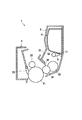
図1に示すように、プロセスカートリッジ1は、ドラムユニット2と、現像ユニット3とを備えている。ドラムユニット2は、感光ドラム21と、感光ドラム21の表面を帯電する帯電ローラ22と、感光ドラム21の表面をクリーニングするためのクリーニングブレード23とを備えている。
As shown in FIG. 1, the
現像ユニット3は、現像剤の一例としてのトナーを収容する可撓性容器4と、可撓性容器4を収容する樹脂製の筐体31と、筐体31内に設けられる回転部材32および供給ローラ33と、現像ローラ34と、層厚規制ブレード35とを備えている。可撓性容器4は、筐体31よりも変形しやすい材料からなる袋状の容器であり、内部のトナーを外部に排出するための排出口H1を有し、当該排出口H1を下に向けた状態で筐体31内に固定されている。なお、可撓性容器4の材料としては、例えば、ポリエチレンテレフタレート(PET)、ポリエチレン(PE)、ポリプロピレン(PP)等を用いればよい。
The developing
排出口H1は、封止部材5によって封止されている。封止部材5は、筐体31よりも変形しやすい材料からなるシート状の部材であり、一端部が可撓性容器4の排出口H1周りの部分に貼り付けられ、他端部が回転部材32に固定されている。なお、封止部材5の材料は、例えば可撓性容器4と同じ材料を用いればよい。
The discharge port H1 is sealed by the sealing
回転部材32は、可撓性容器4の下に配置され、筐体31に対して回転可能に設けられている。回転部材32は、封止部材5を支持し、現像ローラ34が延びる方向である第1方向に沿う軸線を中心に回転可能となっている。回転部材32は、図示せぬ画像形成装置の本体筐体に設けられるモータの駆動力が入力されることで回転駆動されるようになっている。
The rotating
このようなプロセスカートリッジ1は、画像形成装置の本体筐体に着脱可能となっており、印刷制御において以下のように動作する。印刷制御において、まず、帯電ローラ22が感光ドラム21の表面を帯電する。次いで、本体筐体に設けられた露光装置が、帯電された感光ドラム21の表面をレーザ光によって露光することで、感光ドラム21の表面上に静電潜像を形成する。
Such a
一方、回転部材32は、モータから駆動力が入力されることで、回転する。回転部材32の回転により、封止部材5は、回転部材32に巻き取られ、可撓性容器4から剥がされる。これにより、排出口H1が開放されて、排出口H1から供給ローラ33に向けてトナーが排出される。
On the other hand, the rotating
供給ローラ33は、現像ローラ34に接触しながら回転することで、現像ローラ34にトナーを供給する。現像ローラ34上のトナーは、層厚規制ブレード35によって厚さが規制された後、感光ドラム21の静電潜像に供給される。
The
次に、可撓性容器4の構造について図2〜図5を参照して詳細に説明する。なお、図2〜図5においては、理解しやすいように、可撓性容器4の厚さを大きく誇張して図示する等、可撓性容器4を簡略的に図示することとする。また、以下の説明において、方向は、図2に示す方向で説明することとする。ここで、図2に示す左右方向は、可撓性容器4を現像ユニット3に取り付けた状態において現像ローラ34の軸線方向に相当する。図2に示す前後方向は、軸線方向に直交し、かつ、第1壁に直交する第1直交方向に相当する。図2に示す上下方向は、軸線方向および第1直交方向に直交する第2直交方向に相当する。
Next, the structure of the
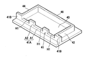
図2および図3に示すように、可撓性容器4は、左右方向に長い中空の略直方体状に形成されており、第1壁としての前壁41と、第2壁としての右壁42と、第3壁としての下壁43と、第4壁としての左壁44と、第5壁としての上壁45と、第6壁としての後壁46とを有している。なお、各壁41〜46は、例えば、複数枚の樹脂製シートを折り曲げたり、溶着したりすることで、一体に構成されている。各壁41〜46は、トナーを収容するための空間を形成している。
As shown in FIGS. 2 and 3, the
前壁41は、トナーを収容する空間を形成するための基部41Aと、基部41Aの左右方向の両端部から左右方向外側に延びる2つのフランジ部41Bとを有している。ここで、図2では、便宜上、基部41Aと各フランジ部41Bとの境界を破線で示す。
The
基部41Aの上下方向の一端部は、上壁45の外面と同じ位置に位置する。基部41Aの上下方向の他端部は、下壁43の内面と同じ位置に位置する。基部41Aの左右方向の一端部は、右壁42の外面と同じ位置に位置する。基部41Aの左右方向の他端部は、左壁44の外面と同じ位置に位置する。左右方向の一端側のフランジ部41Bは、右壁42の外面よりも外側に突出している。左右方向の他端側のフランジ部41Bは、左壁44の外面よりも外側に突出している。そして、基部41Aは、後で詳述する3つの排出口H1を有する。
One end of the
右壁42は、基部41Aの左右方向の一端部に接続されている。右壁42は、基部41Aの左右方向の一端部から後壁46に向けて延びている。言い換えると、右壁42は、基部41Aの左右方向の一端部から、基部41Aに直交(交差)する方向に延びている。右壁42は、左右方向に直交するように配置されている。
The
左壁44は、基部41Aの左右方向の他端部に接続されている。左壁44は、基部41Aの左右方向の他端部から後壁46に向けて延びている。左壁44は、左右方向に直交するように配置されている。左壁44は、左右方向において右壁42と対向している。
The
上壁45は、基部41Aの上下方向の一端部から後壁46に向けて延びている。上壁45は、基部41A、右壁42および左壁44に接続されている。上壁45は、上下方向に直交するように配置されている。
The
後壁46は、前後方向に直交するように配置されている。後壁46は、前後方向において基部41Aと対向している。後壁46は、右壁42、左壁44および上壁45に接続されている。
The
下壁43は、上下方向において上壁45と対向している。下壁43は、前壁41、右壁42、左壁44および後壁46に接続されている。下壁43は、前壁41、右壁42、左壁44および後壁46よりも外側に突出している。下壁43のうち各壁41,42,44,46よりも外側に突出した部分は、現像ユニット3の筐体31に可撓性容器4を取り付けるための取付部となっている。下壁43は、上下方向に直交するように配置されている。つまり、下壁43は、前壁41と右壁42とに直交するように配置されている。
The
各排出口H1は、左右方向に長い矩形の孔である。各排出口H1は、それぞれ間隔を空けて左右方向に並んでいる。排出口H1の左右方向の長さは、41mm以上48mm以下、好ましくは、43mm以上46mm以下となっている。また、排出口H1の上下方向(軸線方向に直交する方向)の長さは、2mm以上7mm以下、好ましくは、3mm以上5mm以下となっている。また、左右方向における、右壁42の内面から左壁44の内面までの距離は、190mm以上210mm以下、好ましくは195mm以上207mm以下となっている。
Each discharge port H1 is a rectangular hole long in the left-right direction. The discharge ports H1 are arranged in the left-right direction at intervals. The length in the left-right direction of the discharge port H1 is 41 mm or more and 48 mm or less, preferably 43 mm or more and 46 mm or less. Moreover, the length of the up-down direction (direction orthogonal to an axial direction) of the discharge port H1 is 2 mm or more and 7 mm or less, Preferably, it is 3 mm or more and 5 mm or less. The distance from the inner surface of the
3つのうち真ん中の排出口H1は、基部41Aの中央部において、右壁42、下壁43、左壁44および上壁45から離れている。
The middle outlet H1 among the three is separated from the
左右方向の一端側の排出口H1は、下壁43および上壁45から離れている。左右方向の一端側の排出口H1は、真ん中の排出口H1から左右方向の一端側に所定距離だけ離れた位置から右壁42まで形成されている。つまり、左右方向の一端側の排出口H1の左右方向の一端側の端縁は、右壁42の内面の延長線上の位置に位置している。
The discharge port H <b> 1 on one end side in the left-right direction is separated from the
左右方向の他端側の排出口H1は、下壁43および上壁45から離れている。左右方向の他端側の排出口H1は、真ん中の排出口H1から左右方向の他端側に所定距離だけ離れた位置から左壁44まで形成されている。つまり、左右方向の他端側の排出口H1の左右方向の他端側の端縁は、左壁44の内面の延長線上に配置されている。
The discharge port H1 on the other end side in the left-right direction is separated from the
基部41Aは、第1連結部A1と、第2連結部A2と、2つの第3連結部A3とを有している。第1連結部A1は、各排出口H1の下に位置している。第1連結部A1は、右壁42から左壁44まで延びて各壁42,44を繋いでいる。
The
第2連結部A2は、各排出口H1の上に位置している。第2連結部A2は、右壁42から左壁44まで延びて各壁42,44を繋いでいる。各第3連結部A3は、各排出口H1の間に位置している。各第3連結部A3は、各連結部A1,A2を繋いでいる。各第3連結部A3は、それぞれ第1連結部A1の一部(第3連結部A3に隣接する部分)と、第2連結部A2の一部(第3連結部A3に隣接する部分)とを介して、下壁43と上壁45とを繋いでいる。
The second connecting portion A2 is located on each discharge port H1. The second connecting portion A2 extends from the
図4および図5に示すように、封止部材5の一端部は、各排出口H1を塞ぐように、前壁41の外面に貼り付けられている。なお、図では、封止部材5の一端部が基部41A内に収まるように貼り付けられているが、封止部材5の貼付位置が多少左右にずれた場合であっても、作業者は右壁42側に封止部材5を折り曲げることなく、封止部材5をフランジ部41Bに貼り付けることが可能となっている。
As shown in FIGS. 4 and 5, one end of the sealing
以上によれば、本実施形態において以下のような効果を得ることができる。
左右方向の一端側の排出口H1が右壁42まで形成されているので、トナーが前壁41と右壁42との間の隅部に残るのを抑えることができる。同様に、左右方向の他端側の排出口H1が左壁44まで形成されているので、トナーが前壁41と左壁44との間の隅部に残るのを抑えることができる。
According to the above, the following effects can be obtained in the present embodiment.
Since the discharge port H1 on one end side in the left-right direction is formed up to the
前壁41が右壁42および左壁44よりも左右方向外側に延びているので、封止部材5の貼付位置が多少左右にずれた場合であっても、作業者は右壁42や左壁44側に封止部材5を折り曲げることなく、封止部材5を前壁41に良好に貼り付けることができる。
Since the
前壁41が、右壁42と左壁44、または、下壁43と上壁45とを繋ぐ各連結部A1〜A3を有しているので、排出口H1周りの剛性を高くすることができる。
Since the
[第2の実施形態]
次に、本発明の第2の実施形態について、適宜図面を参照しながら詳細に説明する。なお、本実施形態は、前記した第1の実施形態に係る可撓性容器4の一部の構造を変更したものであるため、第1の実施形態と略同様の構成要素については、同一符号を付し、その説明を省略することとする。
[Second Embodiment]
Next, a second embodiment of the present invention will be described in detail with reference to the drawings as appropriate. In addition, since this embodiment changes a part of structure of the
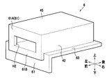
図6および図7に示すように、第2の実施形態に係る可撓性容器6は、第1の実施形態と略同様の右壁42、左壁44、上壁45および後壁46を有する他、第1の実施形態とは異なる前壁61および下壁63と、新たな延出壁67とを有している。なお、第2の実施形態では、前壁61が第1壁に相当する。また、下壁63が第2壁に相当する。また、右壁42が第3壁に相当する。また、上壁45が第4壁に相当する。また、左壁44が第5壁に相当する。また、後壁46が第6壁に相当する。つまり、第2の実施形態では、左右方向に沿って配置された下壁63が、第2壁となっている。
As shown in FIGS. 6 and 7, the
前壁61は、トナーを収容する空間を形成するための基部61Aと、基部61Aの下端部から下方に延びるフランジ部61Bとを有している。フランジ部61Bは、下壁63よりも上下方向の他端側に延びている。
The
下壁63は、第1の実施形態とは異なり、前壁41から外側には突出しない構造となっている。詳しくは、下壁63は、基部61A、右壁42、左壁44および後壁46に接続されている。下壁63は、右壁42、左壁44および後壁46よりも外側に突出している。
Unlike the first embodiment, the
延出壁67は、トナーを収容する空間を形成しない壁である。延出壁67は、下壁63の前後方向の一端部から上下方向の他端側に向けて延びている。延出壁67は、フランジ部61Bの前後方向の他端側に配置されている。延出壁67は、フランジ部61Bよりも上下方向の他端側および左右方向外側に突出している。
The
排出口H2は、基部61Aに1つだけ形成されている。排出口H2は、基部61Aのうち上壁45から所定距離だけ離れた位置から下壁63まで形成されている。つまり、排出口H2の下縁は、下壁63の内面の延長線上に配置されている。また、排出口H2は、右壁42および左壁44から離れて形成されている。
Only one outlet H2 is formed in the
この形態によれば、排出口H2が下壁63まで形成されているので、トナーが前壁61と下壁63との間の隅部に残るのを抑えることができる。また、前壁61が下壁63よりも上下方向の他端側に延びているので、封止部材5の貼付位置が多少上下方向の他端側にずれた場合であっても、作業者は下壁63側に封止部材5を折り曲げることなく、封止部材5を前壁61に良好に貼り付けることができる。
According to this embodiment, since the discharge port H <b> 2 is formed up to the
[第3の実施形態]
次に、本発明の第3の実施形態について、適宜図面を参照しながら詳細に説明する。なお、本実施形態は、前記した第1の実施形態に係る可撓性容器4の一部の構造を変更したものであるため、第1の実施形態と同様の構成要素については、同一符号を付し、その説明を省略することとする。
[Third Embodiment]
Next, a third embodiment of the present invention will be described in detail with reference to the drawings as appropriate. In addition, since this embodiment changes a part of structure of the
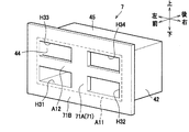
図8および図9に示すように、第3の実施形態に係る可撓性容器7は、第1の実施形態と略同様の右壁42、左壁44、上壁45および後壁46を有する他、第1の実施形態とは異なる前壁71および下壁73を有している。なお、第3の実施形態では、前壁71が第1壁に相当する。下壁73が第2壁に相当する。また、右壁42が第3壁に相当する。また、上壁45が第4壁に相当する。また、左壁44が第5壁に相当する。また、後壁46が第6壁に相当する。
As shown in FIGS. 8 and 9, the
下壁73は、第1の実施形態とは異なり、前壁71、右壁42、左壁44および後壁46から外側に突出しない構造となっている。
Unlike the first embodiment, the
前壁71は、右壁42、下壁73、左壁44および上壁45よりも外側に突出している。詳しくは、前壁71は、トナーを収容する空間を形成するための矩形の基部71Aと、基部71Aの四辺を取り囲む矩形の枠状のフランジ部71Bとを有している。基部71Aは、右壁42、下壁73、左壁44および上壁45の前後方向の一端部に隣接する矩形の枠状部分A11と、矩形の枠状部分A11のうち対向する2辺の部分を連結する十字状の連結部A12とを有している。
The
基部71Aは、4つの排出口H31〜H34を有している。各排出口H31〜H34は、基部71Aの四つの角部に対応するように配置されている。詳しくは、左右方向の他端側、かつ、上下方向の他端側に配置される第1排出口H31は、下壁73から上下方向の一端側に所定距離離れた位置から下壁73まで形成されている。第1排出口H31は、左壁44から左右方向の一端側に所定距離離れた位置から左壁44まで形成されている。つまり、第1排出口H31の上下方向の他端は、下壁73の内面の延長線上に配置されている。また、第1排出口H31の左右方向の他端は、左壁44の内面の延長線上に配置されている。
The
左右方向の一端側、かつ、上下方向の他端側に配置される第2排出口H32は、下壁73から上下方向の一端側に所定距離離れた位置から下壁73まで形成されている。第2排出口H32は、右壁42から左右方向の他端側に所定距離離れた位置から右壁42まで形成されている。つまり、第2排出口H32の上下方向の他端は、下壁73の内面の延長線上に配置されている。また、第2排出口H32の左右方向の一端は、右壁42の内面の延長線上に配置されている。
The second discharge port H32 disposed on one end side in the left-right direction and the other end side in the up-down direction is formed from a position a predetermined distance away from the
図10に示すように、左右方向の他端側、かつ、上下方向の一端側に配置される第3排出口H33は、上壁45から上下方向の他端側に所定距離離れた位置から上壁45まで形成されている。第3排出口H33は、左壁44から左右方向の一端側に所定距離離れた位置から左壁44まで形成されている。つまり、第3排出口H33の上下方向の一端は、上壁45の内面の延長線上に配置されている。また、第3排出口H33の左右方向の他端は、左壁44の内面の延長線上に配置されている。
As shown in FIG. 10, the third discharge port H33 arranged on the other end side in the left-right direction and one end side in the up-down direction is located at a predetermined distance from the
左右方向の一端側、かつ、上下方向の一端側に配置される第4排出口H34は、上壁45から上下方向の他端側に所定距離離れた位置から上壁45まで形成されている。第4排出口H34は、右壁42から左右方向の他端側に所定距離離れた位置から右壁42まで形成されている。つまり、第4排出口H34の上下方向の一端は、上壁45の内面の延長線上に配置されている。また、第4排出口H34の左右方向の一端は、右壁42の内面の延長線上に配置されている。
The 4th discharge port H34 arrange | positioned at the one end side of the left-right direction and the one end side of an up-down direction is formed from the position away from the
この形態によれば、第1排出口H31が下壁73および左壁44まで形成されているので、前壁71と下壁73との間の隅部や前壁71と左壁44との間の隅部にトナーが残るのを抑えることができる。なお、各排出口H32〜H34でも同様の効果を得ることができる。また、前壁71が右壁42、下壁73、左壁44および上壁45よりも外側に突出しているので、封止部材5の貼付位置が左右上下に多少にずれた場合であっても、作業者は封止部材5を前後方向の他端側に折り曲げることなく、封止部材5を前壁71に良好に貼り付けることができる。
According to this embodiment, since the first discharge port H31 is formed up to the
[第4の実施形態]
次に、本発明の第4の実施形態について、適宜図面を参照しながら詳細に説明する。
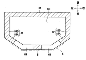
図11〜図13に示すように、第4の実施形態に係る可撓性容器8は、前壁81、右壁82、下壁83、左壁84、上壁85および後壁86を有している。なお、第4の実施形態では、前壁81が第1壁に相当する。右壁82が第2壁に相当する。また、下壁83が第3壁に相当する。また、左壁84が第4壁に相当する。また、上壁85が第5壁に相当する。また、後壁86が第6壁に相当する。
[Fourth Embodiment]
Next, a fourth embodiment of the present invention will be described in detail with reference to the drawings as appropriate.
As shown in FIGS. 11 to 13, the flexible container 8 according to the fourth embodiment has a
前壁81は、前後方向に直交している。右壁82は、前壁81の左右方向の一端部から左右方向外側および前後方向の他端側に向けて斜めに延びる第1部位82Aと、第1部位82Aの前後方向の他端部から後壁86に向けて延びる第2部位82Bとを有している。
The
左壁84は、前壁81の左右方向の他端部から左右方向外側および前後方向の他端側に向けて斜めに延びる第1部位84Aと、第1部位84Aの前後方向の他端部から後壁46に向けて延びる第2部位84Bとを有している。下壁83は、前壁81、右壁82および左壁84を連結している。
The
上壁85は、前壁81、右壁82および左壁84を連結している。後壁86は、右壁82、下壁83、左壁84および上壁85を連結している。
The
前壁81と右壁82の第1部位82Aは、排出口H4を有している。詳しくは、排出口H4は、前壁81と右壁82との境界線を跨ぐように、前壁81と第1部位82Aとに連続して形成されている。
The
また、前壁81と左壁84の第1部位84Aは、排出口H4を有している。詳しくは、排出口H4は、前壁81と左壁84との境界線を跨ぐように、前壁81と第1部位84Aとに連続して形成されている。そして、封止部材5は、前壁81と右壁82の第1部位82Aと左壁84の第1部位84Aとに貼り付けられている。
Further, the
この形態によれば、左右方向の一端側の排出口H4が、前壁81と右壁82の第1部位82Aとに形成されているので、前壁81と右壁82との間の隅部にトナーが残るのを抑えることができる。また、左右方向の他端側の排出口H4でも同様の効果を得ることができる。
According to this embodiment, since the discharge port H4 on one end side in the left-right direction is formed in the
[第5の実施形態]
次に、本発明の第5の実施形態について、適宜図面を参照しながら詳細に説明する。なお、本実施形態は、前記した第3の実施形態に係る可撓性容器7の一部の構造を変更したものであるため、第3の実施形態と同様の構成要素については、同一符号を付し、その説明を省略することとする。
[Fifth Embodiment]
Next, a fifth embodiment of the present invention will be described in detail with reference to the drawings as appropriate. In addition, since this embodiment changes a part of structure of the
図14に示すように、第5の実施形態に係る可撓性容器9は、第3の実施形態に係る可撓性容器7から十字状の連結部A12を取り除いた構造となっている。これにより、この形態では、前壁71の基部71Aが、大きな1つの矩形の排出口H5を有している。
As shown in FIG. 14, the flexible container 9 according to the fifth embodiment has a structure in which the cross-shaped connecting portion A12 is removed from the
排出口H5は、左右方向において、右壁42から左壁44まで形成されている。また、排出口H5は、上下方向において、下壁73から上壁45まで形成されている。つまり、排出口H5の左右方向の一端は、右壁42の内面の延長線上に配置されている。排出口H5の左右方向の他端は、左壁44の内面の延長線上に配置されている。排出口H5の上下方向の他端は、下壁73の内面の延長線上に配置されている。排出口H5の上下方向の一端は、上壁45の内面の延長線上に配置されている。
The discharge port H5 is formed from the
この形態によれば、大きな排出口H5からトナーを良好に排出することができる。 According to this embodiment, the toner can be discharged well from the large discharge port H5.
第1の実施形態では、右壁42、下壁43、左壁44および上壁45を前壁41に対して垂直に設けたが、本発明はこれに限定されず、各壁42〜45は前壁41に交差する方向に延びていればよく、前壁41に対して斜めに配置されていてもよい。
In the first embodiment, the
前記実施形態では、現像ユニット3に本発明を適用したが、本発明はこれに限定されるものではない。例えば、現像ユニットとドラムユニットが一体に構成されたプロセスカートリッジなどに本発明を適用してもよい。
In the above embodiment, the present invention is applied to the developing
なお、現像ローラは、トナーを担持する部分がゴム状の部材で構成されるものであってもよいし、ブラシ状に構成されるものであってもよいし、磁気ローラであってもよい。 The developing roller may be configured such that the toner carrying portion is formed of a rubber-like member, may be formed in a brush shape, or may be a magnetic roller.
3 現像ユニット
4 可撓性容器
5 封止部材
34 現像ローラ
41 前壁
42 右壁
H1 排出口
3 Developing
Claims (13)
前記可撓性容器は、
前記排出口が形成され、前記封止部材が貼り付けられる第1壁と、
前記第1壁に接続され、当該第1壁に交差する方向に延びる第2壁と、を有し、
前記排出口は、少なくとも前記第2壁まで形成されていることを特徴とする現像ユニット。 A flexible container that contains the developer, a sealing member that seals a developer outlet formed in the flexible container, a developing roller that extends in a first direction, and the sealing member A rotating member that supports and rotates about an axis extending in the first direction;
The flexible container is
A first wall on which the discharge port is formed and the sealing member is attached;
A second wall connected to the first wall and extending in a direction intersecting the first wall;
The developing unit, wherein the discharge port is formed at least up to the second wall.
前記第1壁は、前記第2壁よりも前記軸線方向外側に延びていることを特徴とする請求項1に記載の現像ユニット。 The second wall is disposed so as to intersect the axial direction of the developing roller,
The developing unit according to claim 1, wherein the first wall extends outward in the axial direction from the second wall.
前記第1壁は、前記第2壁よりも外側に延びていることを特徴とする請求項1に記載の現像ユニット。 The second wall is disposed along an axial direction of the developing roller;
The developing unit according to claim 1, wherein the first wall extends outward from the second wall.
前記第1壁と前記第2壁とに交差する第3壁と、
前記第2壁と対向する第4壁と、
前記第3壁と対向する第5壁と、を有し、
前記第1壁は、前記第2壁、前記第3壁、前記第4壁および前記第5壁よりも外側に延びていることを特徴とする請求項1から請求項3のいずれか1項に記載の現像ユニット。 The flexible container is
A third wall intersecting the first wall and the second wall;
A fourth wall facing the second wall;
A fifth wall facing the third wall;
The first wall according to any one of claims 1 to 3, wherein the first wall extends outward from the second wall, the third wall, the fourth wall, and the fifth wall. The developing unit described.
前記封止部材は、前記第1壁と前記第2壁とに貼り付けられていることを特徴とする請求項1に記載の現像ユニット。 The second wall is disposed obliquely with respect to the first wall;
The developing unit according to claim 1, wherein the sealing member is attached to the first wall and the second wall.
前記2つの壁の間の距離は、190mm以上210mm以下であることを特徴とする請求項1から請求項11のいずれか1項に記載の現像ユニット。 The flexible container has two walls facing each other in the first direction,
The developing unit according to any one of claims 1 to 11, wherein a distance between the two walls is 190 mm or more and 210 mm or less.
Priority Applications (2)
| Application Number | Priority Date | Filing Date | Title |
|---|---|---|---|
| JP2016061385A JP2017173676A (en) | 2016-03-25 | 2016-03-25 | Developing unit |
| CN201720157703.4U CN206618955U (en) | 2016-03-25 | 2017-02-21 | Developing cell |
Applications Claiming Priority (1)
| Application Number | Priority Date | Filing Date | Title |
|---|---|---|---|
| JP2016061385A JP2017173676A (en) | 2016-03-25 | 2016-03-25 | Developing unit |
Publications (1)
| Publication Number | Publication Date |
|---|---|
| JP2017173676A true JP2017173676A (en) | 2017-09-28 |
Family
ID=59971976
Family Applications (1)
| Application Number | Title | Priority Date | Filing Date |
|---|---|---|---|
| JP2016061385A Pending JP2017173676A (en) | 2016-03-25 | 2016-03-25 | Developing unit |
Country Status (2)
| Country | Link |
|---|---|
| JP (1) | JP2017173676A (en) |
| CN (1) | CN206618955U (en) |
Cited By (1)
| Publication number | Priority date | Publication date | Assignee | Title |
|---|---|---|---|---|
| WO2022102370A1 (en) * | 2020-11-10 | 2022-05-19 | キヤノン株式会社 | Toner supply container and mounting unit |
-
2016
- 2016-03-25 JP JP2016061385A patent/JP2017173676A/en active Pending
-
2017
- 2017-02-21 CN CN201720157703.4U patent/CN206618955U/en active Active
Cited By (2)
| Publication number | Priority date | Publication date | Assignee | Title |
|---|---|---|---|---|
| WO2022102370A1 (en) * | 2020-11-10 | 2022-05-19 | キヤノン株式会社 | Toner supply container and mounting unit |
| CN116420118A (en) * | 2020-11-10 | 2023-07-11 | 佳能株式会社 | Toner supply container and mounting unit |
Also Published As
| Publication number | Publication date |
|---|---|
| CN206618955U (en) | 2017-11-07 |
Similar Documents
| Publication | Publication Date | Title |
|---|---|---|
| US9316991B2 (en) | Developer cartridge | |
| US9304441B2 (en) | Developer accommodating container, developer accommodating unit, process cartridge and image forming apparatus | |
| EP2786210B1 (en) | Developer accommodating container, process cartridge and electrophotographic image forming apparatus | |
| US9341983B2 (en) | Developer accommodating unit, developing device, process cartridge and image forming apparatus | |
| JP5103895B2 (en) | Developer container, assembling method and reproducing method of developer container | |
| JP6406928B2 (en) | Developer container, developer storage unit, process cartridge, and image forming apparatus | |
| JP2014056025A (en) | Developer storage container, process cartridge, and image forming apparatus | |
| US20170285527A1 (en) | Developer Cartridge Provided with Casing and Developer Accommodating Unit Detachably Supported Thereto | |
| JP2017173676A (en) | Developing unit | |
| JP5891681B2 (en) | Developer cartridge | |
| JP4591474B2 (en) | Method for regenerating developer container | |
| JP5142894B2 (en) | Developing device and process cartridge | |
| JP2016142873A (en) | Cartridge and cover | |
| JP4729317B2 (en) | Packaging material and toner container for replacement toner container to be attached to and detached from the image forming apparatus | |
| JP6222920B2 (en) | Developing device, process cartridge, and image forming apparatus | |
| JP4867558B2 (en) | Image forming apparatus, developing apparatus, developer conveying apparatus, developer stirring apparatus, image forming unit, and powder conveying apparatus | |
| JP6699312B2 (en) | Developer cartridge | |
| JP5568500B2 (en) | Toner storage container and image forming apparatus | |
| JP5802800B2 (en) | Toner storage container and image forming apparatus | |
| JP2014016495A (en) | Cartridge | |
| JP6256014B2 (en) | Toner supply device, process cartridge, and image forming apparatus | |
| WO2016204196A1 (en) | Toner replenishment method, toner cartridge production method, recycled toner cartridge, and toner cartridge recycling method | |
| JP5802799B2 (en) | Toner conveying device and image forming apparatus | |
| JP5802801B2 (en) | Toner storage container and image forming apparatus | |
| WO2017002856A1 (en) | Toner replenishment method, toner cartridge production method, and toner cartridge |