EP4246151B1 - Messsystem für ein breitbandsignal - Google Patents
Messsystem für ein breitbandsignal Download PDFInfo
- Publication number
- EP4246151B1 EP4246151B1 EP22162864.7A EP22162864A EP4246151B1 EP 4246151 B1 EP4246151 B1 EP 4246151B1 EP 22162864 A EP22162864 A EP 22162864A EP 4246151 B1 EP4246151 B1 EP 4246151B1
- Authority
- EP
- European Patent Office
- Prior art keywords
- band
- measurement system
- sub
- unit
- respective sub
- Prior art date
- Legal status (The legal status is an assumption and is not a legal conclusion. Google has not performed a legal analysis and makes no representation as to the accuracy of the status listed.)
- Active
Links
Images

Classifications
-
- G—PHYSICS
- G01—MEASURING; TESTING
- G01R—MEASURING ELECTRIC VARIABLES; MEASURING MAGNETIC VARIABLES
- G01R29/00—Arrangements for measuring or indicating electric quantities not covered by groups G01R19/00 - G01R27/00
- G01R29/08—Measuring electromagnetic field characteristics
- G01R29/0864—Measuring electromagnetic field characteristics characterised by constructional or functional features
- G01R29/0871—Complete apparatus or systems; circuits, e.g. receivers or amplifiers
-
- G—PHYSICS
- G01—MEASURING; TESTING
- G01R—MEASURING ELECTRIC VARIABLES; MEASURING MAGNETIC VARIABLES
- G01R23/00—Arrangements for measuring frequencies; Arrangements for analysing frequency spectra
- G01R23/16—Spectrum analysis; Fourier analysis
- G01R23/165—Spectrum analysis; Fourier analysis using filters
Definitions
- the present disclosure relates to measurement of broadband signals, and in particular to a measurement system in this respect.
- EMI electromagnetic interference
- RF radio frequency
- the critical components including e.g. a first mixer of a heterodyne receiver or analog/digital converter at an intermediate frequency (IF) of a receiver or the baseband of a direct conversion receiver. Then, the measurement is done in a time-consuming sequential manner for every preselector filter path and measurement frequency.
- the document US 7 541 959 B1 which pertains to the conversion of analog signals to digital format, particularly applicable for capturing wideband signals where the desired dynamic range of the system cannot be achieved by existing analog to digital converters.
- the measurement may involve Fast Fourier Transform (FFT) methods to accelerate the measurement.
- FFT Fast Fourier Transform
- the present disclosure aims to improve a measurement of broadband pulse signals of the background art.
- An objective is to shorten a test time.
- An aspect of the present disclosure relates to a measurement system for a broadband signal.
- the system comprises a cross-over network, including an input port for the broadband signal; a plurality of output ports; and a plurality of frequency dividers, being configured to supply respective sub-bands of the broadband signal to the plurality of output ports.
- the plurality of frequency dividers comprises one or more of a low-pass filter and a high-pass filter.
- DUTs like vehicles can be put into different test modes (for example acceleration from 10m/s to 30m/s on a test bench), wherein the spectrum the DUT emits is continuously monitored on a wide range. Any peak, even if it only occurs once (for example at 25m/s) can be detected with the measurement system according to the invention.
- the processing unit may comprise a respective analog/digital converter, ADC, unit for the respective sub-band.
- ADC analog/digital converter
- the processing unit may comprise a respective analog/digital converter, ADC, unit for the respective sub-band.
- ADC analog/digital converter
- the RF signal of the respective sub-band is not mixed down before fed to the respective ADC.
- the respective ADC is configured to digitize the RF signal of the assigned sub-band in the original frequency but with a reduced bandwidth of that sub-band.
- the broadband signal may comprise a baseband signal.
- the broadband signal may comprise an intermediate frequency, IF, signal.
- the respective ADC unit for the respective sub-band may be configured to digitally sample the respective sub-band of the IF signal.
- the respective ADC unit for the respective sub-band may be configured to digitally mix down the respective sub-band of the IF signal to the baseband.
- the respective ADC unit for the respective sub-band may be configured to decimate a sampling rate of the respective sub-band of the IF signal.
- the ADC can be operated at 3 GHz with a resolution of 16 bit, but the decimation may result in a reduced data rate, such as e.g. 500 MHz.
- the processing unit may comprise a respective Fast Fourier Transform, FFT, unit for the respective sub-band.
- the respective FFT unit may be configured to perform a first plurality of concurrent FFT calculations in accordance with a second plurality of frequency bins being spread over the respective sub-band.
- the respective frequency bin may be associated with at least 20.000, 40.000, 80.000, 160.000, 250.000, 320.000, 400.000 or 480.000 FFT calculations per second.
- the processing unit may comprise a respective detector unit for the respective sub-band; and the respective detector unit may be configured to perform a plurality of concurrent analyses of the respective sub-band in respect of one or more detection criteria.
- the respective detector unit for the respective sub-band may comprise a number of detectors for the respective frequency bin.
- the respective detector unit for the respective sub-band may comprise a plurality of concurrently operable detectors for the respective frequency bin. In that case, all the frequency bins obtained from all the sub-bands are analyzed in parallel by the detectors.
- a first detector of the plurality of detectors of the respective frequency bin may be configured for peak detection; a second detector of the plurality of detectors of the respective frequency bin may be configured for quasi-peak detection; and a third detector of the plurality of detectors of the respective frequency bin may be configured for average detection.
- each frequency bin can be analyzed by a plurality of detectors at the same time.
- the cross-over network may further comprise an amplifier arranged between subsequent frequency dividers of the plurality of frequency dividers.
- the measurement system may further comprise a display unit.
- the processing unit may further be configured to display the respective analyzed sub-bands on the display unit.
- a broadband signal such as a baseband signal or an IF signal of a heterodyne receiver
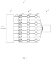
- FIG. 1 illustrates a measurement system 1 in accordance with the present disclosure for a broadband signal.
- the broadband signal to be analyzed may comprise a baseband signal, or an intermediate frequency, IF, signal, particularly of a heterodyne receiver.
- IF intermediate frequency
- a broad frequency range has to be measured. This in turn requires a high dynamic range of the receiver due to a significant difference between the peak values of the signal.
- a pulse signal as well as a modulated signal have broad spectra.
- the system 1 comprises a cross-over network 11, including an input port 111 for the broadband signal, and a plurality of output ports 112.
- the cross-over network 11 is configured to supply respective sub-bands of the broadband signal to the plurality of output ports 112.
- the cross-over network 11 is configured to preselect the respective sub-band of the broadband signal of a respective output port 11.
- the system 1 further comprises a processing unit 12, being configured to analyze the respective sub-bands of the broadband signal concurrently. Concurrently means that the respective sub-bands of the broadband signal are analyzed at the same time by dedicated means.
- the processing unit 12 may comprise a respective analog/digital converter, ADC, unit 121 for the respective sub-band.
- the respective ADC unit 121 for the respective sub-band may be configured to digitally sample the respective sub-band of the IF signal.
- the ADC units 121 are very fast (in compliance with the Shannon theorem) and operable on respective sub-bands of the original frequency band (for example 30 MHz to 1.000 MHz) of the broadband signal.
- the signal paths upstream the ADC units 121 are free of mixers.
- the respective ADC unit 121 for the respective sub-band may be configured to digitally mix down the respective sub-band of the IF signal to the baseband.
- the respective ADC unit 121 for the respective sub-band may be configured to decimate a sampling rate of the respective sub-band of the IF signal.
- the processing unit 12 may further comprise a respective Fast Fourier Transform, FFT, unit 122 for the respective sub-band.
- the respective FFT unit 122 may be configured to perform a first plurality of concurrent FFT calculations in accordance with a second plurality of frequency bins being spread over the respective sub-band.
- the respective FFT unit 122 may be arranged downstream of the respective ADC unit 121.
- the respective FFT unit 122 may be configured to perform a 1024, 2048 or 4096-point FFT, for example.
- the respective frequency bin may represent 60 kHz or 120 kHz of bandwidth, for example, and may be associated with preferably more than 20.000, 40.000, 80.000, 160.000, 250.000, 320.000 or more than 400.000 FFT calculations per second. More preferably the respective frequency bin is associated with (at least) 480.000 FFT calculations per second.
- the processing unit 12 may comprise a respective detector unit 123 for the respective sub-band.
- the detector unit 123 may be arranged downstream of the respective FFT unit 122.
- the respective detector unit 123 may be configured to perform a plurality of concurrent analyses of the respective sub-band in respect of one or more detection criteria, such as peak detection, quasi-peak detection and average detection.
- the respective detector unit 123 for the respective sub-band may comprise a plurality of concurrently operable detectors for the respective frequency bin.
- a first detector of the plurality of detectors of the respective frequency bin may be configured for peak detection; a second detector of the plurality of detectors of the respective frequency bin may be configured for quasi-peak detection; and a third detector of the plurality of detectors of the respective frequency bin may be configured for average detection.
- the measurement system 1 may further comprise a display unit 13.
- the processing unit 12 may further be configured to display the respective analyzed sub-bands on the display unit 13.
- each frequency bin may be associated with for example 480.000 FFT calculations per second, and an exemplary plurality of three concurrently operable detectors may be used for the respective frequency bin.
- FIG. 2 illustrates a cross-over network 111 in accordance with the present disclosure of the measurement system 1 of FIG. 1 .
- the cross-over network 11 already mentioned in connection with FIG. 1 includes a plurality of frequency dividers 113, being configured to supply respective sub-bands of the broadband signal to the plurality of output ports 112.
- a frequency divider may refer to a frequency-selective filter.
- the plurality of frequency dividers 113 comprises one or more of a low-pass filter and a high-pass filter as follows: Starting from the input port 111, a low-pass filter may be provided as a first frequency divider 113. Preferably frequencies below 1 GHz can pass without significant attenuation. As such, a frequency band of interest, such as 30 MHz to 1.000 MHz according to the CISPR standard, can be analyzed.
- the first splitting stage may comprise a plurality of frequency-selective dividers 113 (in the embodiment there are two dividers, one of them being referenced as such).
- the first splitting stage may supply frequency bands of 30 to 440 MHz and 440 to 1.000 MHz.
- a second splitting stage may be provided downstream the first splitting stage.
- the second splitting stage may comprise a plurality of frequency-selective dividers 113 (in the embodiment there are four dividers, one of them being referenced as such).
- the second splitting stage may further subdivide the frequency bands supplied by the first splitting stage.
- the second splitting stage may supply frequency bands of 30 to 210 MHz, 210 to 440 MHz, 440 to 720 MHz, and 720 to 1.000 MHz, respectively.
- the first and second splitting stages are configured in such a way that the input port 111 of the cross-over network 11 matches a predefined impedance. This is easier to achieve if high-pass filters and low-pass filters are used rather than band-pass filters, because the voltage standing wave ratio (VSWR) must meet particular criteria.
- Each of the filters implies a signal attenuation preferably as low as 0,5 to 1,0 dB.
- a third splitting stage may be provided downstream the second splitting stage.
- the third splitting stage may comprise a plurality of composite dividers 113', 113" (in the embodiment there are four such dividers, one of them being referenced as such).
- a composite divider 113', 113" may comprise a series connection of a frequency-agnostic 3dB coupler 113' (i.e., a power splitter) and a frequency-selective filter 113", which jointly behave as a frequency-selective frequency divider.
- the dividers 113', 113" of the third splitting stage are connected to the frequency dividers 113 of the second splitting stage directly or indirectly.
- the dividers of the third splitting stage may further include attenuators for levelling out any power level imbalances among the plurality of sub-bands, since the power levels of the sub-bands should be the same.
- the 3dB couplers 113' increase an isolation between the sub-bands.
- the third/last splitting stage may supply the respective sub-bands of the broadband signal to the plurality of output ports 112.
- eight sub-bands are available at the output ports 112 of the cross-over network 11.
- a different number of sub-bands could be provided.
- the cross-over network 11 may further comprise an amplifier 114 arranged between subsequent frequency dividers 113, 113', 113" of the plurality of frequency dividers 113.
- the attenuation added before an amplifier should be kept to a minimum.
- no power dividers for example 3dB-couplers
- low-pass filters and/or high-pass filters should be used.
- a pre-amplifier such as a low-noise amplifier (LNA) may selectively be inserted into the signal path by means of switching devices.
- LNA low-noise amplifier
- Such a pre-amplifier may be added after each frequency divider 113 of the first splitting stage.
- pre-amplifiers may be arranged (for example an LNA).
- the amplifiers may be inserted into the signal path by switching devices (as shown).
- the pre-amplifier is used only for analysis of low-power broadband signals.
- the amplifier could amplify the signal by a factor of 20 dB, for example.
Landscapes
- Physics & Mathematics (AREA)
- Electromagnetism (AREA)
- General Physics & Mathematics (AREA)
- Monitoring And Testing Of Transmission In General (AREA)
- Measurement Of Resistance Or Impedance (AREA)
Claims (15)
- Messsystem (1) für ein Breitbandsignal, umfassendeine Frequenzweiche (11), einschließlicheinen Eingangsanschluss (111) für das Breitbandsignal;eine Vielzahl von Ausgangsanschlüssen (112); undeine Vielzahl von Frequenzteilern (113), die konfiguriert sind, um entsprechende Teilbänder des Breitbandsignals an die Vielzahl von Ausgangsanschlüssen (112) zu liefern; undeine Verarbeitungseinheit (12), die konfiguriert ist, um die entsprechenden Teilbänder des Breitbandsignals zeitgleich zu analysieren;die Vielzahl von Frequenzteilern (113) umfassend einen oder mehrere von einem Tiefpassfilter und einem Hochpassfilter.
- Messsystem (1) nach Anspruch 1,
die Verarbeitungseinheit (12) umfassend eine entsprechende Analog-Digital-Umsetzereinheit, ADC-Einheit, (121), für das entsprechende Teilband. - Messsystem (1) nach Anspruch 1 oder 2,
das Breitbandsignal umfassend ein Basisbandsignal. - Messsystem (1) nach Anspruch 1 oder 2,
das Breitbandsignal umfassend ein Zwischenfrequenzsignal (ZF-Signal). - Messsystem (1) nach Anspruch 4,
wobei die entsprechende ADC-Einheit (121) für das entsprechende Teilband konfiguriert ist, um das entsprechende Teilband des ZF-Signals digital abzutasten. - Messsystem (1) nach Anspruch 4,
wobei die entsprechende ADC-Einheit (121) für das entsprechende Teilband konfiguriert ist, um das entsprechende Teilband des ZF-Signals auf das Basisband digital abzumischen. - Messsystem (1) nach Anspruch 4 oder 6,
wobei die entsprechende ADC-Einheit (121) für das entsprechende Teilband konfiguriert ist, um eine Abtastrate des entsprechenden Teilbands des ZF-Signals zu dezimieren. - Messsystem (1) nach einem der vorstehenden Ansprüche,die Verarbeitungseinheit (12) umfassend eine entsprechende Fast Fourier Transform-Einheit, FFT-Einheit, (122), für das entsprechende Teilband; undwobei die entsprechende FFT-Einheit (122) konfiguriert ist, um eine erste Vielzahl zeitgleicher FFT-Berechnungen gemäß einer zweiten Vielzahl von Frequenzbereichen durchzuführen, die über das entsprechende Teilband verteilt sind.
- Messsystem (1) nach Anspruch 8,
wobei dem entsprechenden Frequenzbereich mindestens 20.000, 40.000, 80.000, 160.000, 250.000, 320.000, 400.000 oder 480.000 FFT-Berechnungen pro Sekunde zugeordnet sind. - Messsystem (1) nach Anspruch 8 oder 9,die Verarbeitungseinheit (12) umfassend eine entsprechende Detektoreinheit (123) für das entsprechende Teilband; undwobei die entsprechende Detektoreinheit (123) konfiguriert ist, um eine Vielzahl zeitgleicher Analysen des entsprechenden Teilbandes entsprechend eines oder mehrerer Erkennungskriterien durchzuführen.
- Messsystem (1) nach Anspruch 10,
die entsprechende Detektoreinheit (123) für das entsprechende Teilband umfassend eine Anzahl von Detektoren für den entsprechenden Frequenzbereich. - Messsystem (1) nach Anspruch 10,
die entsprechende Detektoreinheit (123) für das entsprechende Teilband umfassend eine Vielzahl zeitgleich betreibbarer Detektoren für den entsprechenden Frequenzbereich. - Messsystem (1) nach Anspruch 12,wobei ein erster Detektor der Vielzahl von Detektoren des entsprechenden Frequenzbereichs für eine Spitzenerkennung konfiguriert ist;wobei ein zweiter Detektor der Vielzahl von Detektoren des entsprechenden Frequenzbereichs für eine Quasi-Spitzenerkennung konfiguriert ist; undwobei ein dritter Detektor der Vielzahl von Detektoren des entsprechenden Frequenzbereichs für eine Durchschnittserkennung konfiguriert ist.
- Messsystem (1) nach einem der vorstehenden Ansprüche,die Frequenzweiche (11) ferner umfassendeinen Verstärker (114), der zwischen nachfolgenden Frequenzteilern (113, 113', 113") der Vielzahl von Frequenzteilern (113) angeordnet ist.
- Messsystem (1) nach einem der vorstehenden Ansprüche, ferner umfassendeine Anzeigeeinheit (13);wobei die Verarbeitungseinheit (12) ferner konfiguriert ist, um die entsprechenden analysierten Teilbänder auf der Anzeigeeinheit (13) anzuzeigen.
Priority Applications (1)
| Application Number | Priority Date | Filing Date | Title |
|---|---|---|---|
| EP22162864.7A EP4246151B1 (de) | 2022-03-18 | 2022-03-18 | Messsystem für ein breitbandsignal |
Applications Claiming Priority (1)
| Application Number | Priority Date | Filing Date | Title |
|---|---|---|---|
| EP22162864.7A EP4246151B1 (de) | 2022-03-18 | 2022-03-18 | Messsystem für ein breitbandsignal |
Publications (2)
| Publication Number | Publication Date |
|---|---|
| EP4246151A1 EP4246151A1 (de) | 2023-09-20 |
| EP4246151B1 true EP4246151B1 (de) | 2025-05-14 |
Family
ID=80820147
Family Applications (1)
| Application Number | Title | Priority Date | Filing Date |
|---|---|---|---|
| EP22162864.7A Active EP4246151B1 (de) | 2022-03-18 | 2022-03-18 | Messsystem für ein breitbandsignal |
Country Status (1)
| Country | Link |
|---|---|
| EP (1) | EP4246151B1 (de) |
Families Citing this family (1)
| Publication number | Priority date | Publication date | Assignee | Title |
|---|---|---|---|---|
| EP4531289A1 (de) * | 2023-09-28 | 2025-04-02 | Rohde & Schwarz GmbH & Co. KG | Hochfrequenzempfängermodul und signalanalysevorrichtung |
Family Cites Families (2)
| Publication number | Priority date | Publication date | Assignee | Title |
|---|---|---|---|---|
| US7541959B1 (en) * | 2003-04-07 | 2009-06-02 | Photonics Products, Inc. | High speed signal processor |
| JP5049305B2 (ja) * | 2008-03-10 | 2012-10-17 | アンリツ株式会社 | 周波数変換装置 |
-
2022
- 2022-03-18 EP EP22162864.7A patent/EP4246151B1/de active Active
Also Published As
| Publication number | Publication date |
|---|---|
| EP4246151A1 (de) | 2023-09-20 |
Similar Documents
| Publication | Publication Date | Title |
|---|---|---|
| US8314604B2 (en) | Apparatus and method for spurious-free signal range measurement for RF circuitry | |
| US7116092B2 (en) | Integrated spectrum analyzer circuits and methods for providing on-chip diagnostics | |
| WO2018032645A1 (zh) | 一种宽带宽频率捷变信号测量仪器及测量方法 | |
| US6621277B2 (en) | Phase noise measurement module and method for a spectrum analyzer | |
| US20110093225A1 (en) | Method of making frequency domain measurements on a time domain instrument | |
| CN111464196B (zh) | 一种接收机 | |
| CN106886002B (zh) | 一种频谱分析仪的校准方法 | |
| CN106341195A (zh) | 一种面向射频前端的校准系统及校准方法 | |
| EP4246151A1 (de) | Messsystem für ein breitbandsignal | |
| CN108459203B (zh) | 一种超宽带扫频脉冲功率检波装置及方法 | |
| CN107885275B (zh) | 一种信号源分析仪的宽频段中频的自动调理装置和方法 | |
| CN108847902B (zh) | 一种噪声信号功率的测量电路和测量方法 | |
| CN210327547U (zh) | 一种实时频谱监测设备 | |
| US20080097710A1 (en) | Method for Measuring the Phase Jitter of a High-Frequency Signal and a Measuring Device for the Implementation of This Method | |
| CN219268863U (zh) | 一种实时监测多路信号的设备 | |
| Keller | A new concept for a wideband FFT-Based EMI receiver | |
| Lee | Wideband I/Q demodulators: measurement technique and matching characteristics | |
| US20050207512A1 (en) | Multichannel simultaneous real time spectrum analysis with offset frequency trigger | |
| US20030057964A1 (en) | Method of and an apparatus for collecting RF input and output and biasing signal data of a device under test | |
| US20070021934A1 (en) | Measuring or test device comprising interchangeable functional units | |
| CN222994664U (zh) | 一种脉冲体制雷达接收机调试平台 | |
| CN210604778U (zh) | 一种频率特性分析仪 | |
| Power et al. | The design and initial testing of a beam phase and energy measurement for LEDA | |
| CN118484127B (zh) | 一种腔式探头束流信号的一体化射频直接采样处理器 | |
| CN117825801B (zh) | 一种集成式宽带信号综测仪及系统控制方法 |
Legal Events
| Date | Code | Title | Description |
|---|---|---|---|
| PUAI | Public reference made under article 153(3) epc to a published international application that has entered the european phase |
Free format text: ORIGINAL CODE: 0009012 |
|
| STAA | Information on the status of an ep patent application or granted ep patent |
Free format text: STATUS: THE APPLICATION HAS BEEN PUBLISHED |
|
| STAA | Information on the status of an ep patent application or granted ep patent |
Free format text: STATUS: REQUEST FOR EXAMINATION WAS MADE |
|
| AK | Designated contracting states |
Kind code of ref document: A1 Designated state(s): AL AT BE BG CH CY CZ DE DK EE ES FI FR GB GR HR HU IE IS IT LI LT LU LV MC MK MT NL NO PL PT RO RS SE SI SK SM TR |
|
| 17P | Request for examination filed |
Effective date: 20230829 |
|
| RBV | Designated contracting states (corrected) |
Designated state(s): AL AT BE BG CH CY CZ DE DK EE ES FI FR GB GR HR HU IE IS IT LI LT LU LV MC MK MT NL NO PL PT RO RS SE SI SK SM TR |
|
| GRAP | Despatch of communication of intention to grant a patent |
Free format text: ORIGINAL CODE: EPIDOSNIGR1 |
|
| STAA | Information on the status of an ep patent application or granted ep patent |
Free format text: STATUS: GRANT OF PATENT IS INTENDED |
|
| INTG | Intention to grant announced |
Effective date: 20250220 |
|
| GRAS | Grant fee paid |
Free format text: ORIGINAL CODE: EPIDOSNIGR3 |
|
| GRAA | (expected) grant |
Free format text: ORIGINAL CODE: 0009210 |
|
| STAA | Information on the status of an ep patent application or granted ep patent |
Free format text: STATUS: THE PATENT HAS BEEN GRANTED |
|
| P01 | Opt-out of the competence of the unified patent court (upc) registered |
Free format text: CASE NUMBER: APP_11768/2025 Effective date: 20250311 |
|
| AK | Designated contracting states |
Kind code of ref document: B1 Designated state(s): AL AT BE BG CY CZ DE DK EE ES FI FR GB GR HR HU IS IT LT LU LV MC MK MT NL NO PL PT RO RS SE SI SK SM TR |
|
| RBV | Designated contracting states (corrected) |
Designated state(s): AL AT BE BG CY CZ DE DK EE ES FI FR GB GR HR HU IS IT LT LU LV MC MK MT NL NO PL PT RO RS SE SI SK SM TR |
|
| REG | Reference to a national code |
Ref country code: GB Ref legal event code: FG4D |
|
| REG | Reference to a national code |
Ref country code: DE Ref legal event code: R096 Ref document number: 602022014519 Country of ref document: DE |
|
| REG | Reference to a national code |
Ref country code: NL Ref legal event code: MP Effective date: 20250514 |
|
| PG25 | Lapsed in a contracting state [announced via postgrant information from national office to epo] |
Ref country code: PT Free format text: LAPSE BECAUSE OF FAILURE TO SUBMIT A TRANSLATION OF THE DESCRIPTION OR TO PAY THE FEE WITHIN THE PRESCRIBED TIME-LIMIT Effective date: 20250915 Ref country code: FI Free format text: LAPSE BECAUSE OF FAILURE TO SUBMIT A TRANSLATION OF THE DESCRIPTION OR TO PAY THE FEE WITHIN THE PRESCRIBED TIME-LIMIT Effective date: 20250514 Ref country code: ES Free format text: LAPSE BECAUSE OF FAILURE TO SUBMIT A TRANSLATION OF THE DESCRIPTION OR TO PAY THE FEE WITHIN THE PRESCRIBED TIME-LIMIT Effective date: 20250514 |
|
| REG | Reference to a national code |
Ref country code: LT Ref legal event code: MG9D |
|
| PG25 | Lapsed in a contracting state [announced via postgrant information from national office to epo] |
Ref country code: NO Free format text: LAPSE BECAUSE OF FAILURE TO SUBMIT A TRANSLATION OF THE DESCRIPTION OR TO PAY THE FEE WITHIN THE PRESCRIBED TIME-LIMIT Effective date: 20250814 Ref country code: GR Free format text: LAPSE BECAUSE OF FAILURE TO SUBMIT A TRANSLATION OF THE DESCRIPTION OR TO PAY THE FEE WITHIN THE PRESCRIBED TIME-LIMIT Effective date: 20250815 |
|
| PG25 | Lapsed in a contracting state [announced via postgrant information from national office to epo] |
Ref country code: NL Free format text: LAPSE BECAUSE OF FAILURE TO SUBMIT A TRANSLATION OF THE DESCRIPTION OR TO PAY THE FEE WITHIN THE PRESCRIBED TIME-LIMIT Effective date: 20250514 Ref country code: PL Free format text: LAPSE BECAUSE OF FAILURE TO SUBMIT A TRANSLATION OF THE DESCRIPTION OR TO PAY THE FEE WITHIN THE PRESCRIBED TIME-LIMIT Effective date: 20250514 |
|
| REG | Reference to a national code |
Ref country code: AT Ref legal event code: MK05 Ref document number: 1795204 Country of ref document: AT Kind code of ref document: T Effective date: 20250514 |
|
| PG25 | Lapsed in a contracting state [announced via postgrant information from national office to epo] |
Ref country code: BG Free format text: LAPSE BECAUSE OF FAILURE TO SUBMIT A TRANSLATION OF THE DESCRIPTION OR TO PAY THE FEE WITHIN THE PRESCRIBED TIME-LIMIT Effective date: 20250514 |
|
| PG25 | Lapsed in a contracting state [announced via postgrant information from national office to epo] |
Ref country code: HR Free format text: LAPSE BECAUSE OF FAILURE TO SUBMIT A TRANSLATION OF THE DESCRIPTION OR TO PAY THE FEE WITHIN THE PRESCRIBED TIME-LIMIT Effective date: 20250514 |
|
| PG25 | Lapsed in a contracting state [announced via postgrant information from national office to epo] |
Ref country code: AT Free format text: LAPSE BECAUSE OF FAILURE TO SUBMIT A TRANSLATION OF THE DESCRIPTION OR TO PAY THE FEE WITHIN THE PRESCRIBED TIME-LIMIT Effective date: 20250514 |
|
| PG25 | Lapsed in a contracting state [announced via postgrant information from national office to epo] |
Ref country code: RS Free format text: LAPSE BECAUSE OF FAILURE TO SUBMIT A TRANSLATION OF THE DESCRIPTION OR TO PAY THE FEE WITHIN THE PRESCRIBED TIME-LIMIT Effective date: 20250814 |
|
| PG25 | Lapsed in a contracting state [announced via postgrant information from national office to epo] |
Ref country code: IS Free format text: LAPSE BECAUSE OF FAILURE TO SUBMIT A TRANSLATION OF THE DESCRIPTION OR TO PAY THE FEE WITHIN THE PRESCRIBED TIME-LIMIT Effective date: 20250914 |
|
| PG25 | Lapsed in a contracting state [announced via postgrant information from national office to epo] |
Ref country code: LV Free format text: LAPSE BECAUSE OF FAILURE TO SUBMIT A TRANSLATION OF THE DESCRIPTION OR TO PAY THE FEE WITHIN THE PRESCRIBED TIME-LIMIT Effective date: 20250514 |
|
| PG25 | Lapsed in a contracting state [announced via postgrant information from national office to epo] |
Ref country code: DK Free format text: LAPSE BECAUSE OF FAILURE TO SUBMIT A TRANSLATION OF THE DESCRIPTION OR TO PAY THE FEE WITHIN THE PRESCRIBED TIME-LIMIT Effective date: 20250514 Ref country code: SM Free format text: LAPSE BECAUSE OF FAILURE TO SUBMIT A TRANSLATION OF THE DESCRIPTION OR TO PAY THE FEE WITHIN THE PRESCRIBED TIME-LIMIT Effective date: 20250514 |
|
| PG25 | Lapsed in a contracting state [announced via postgrant information from national office to epo] |
Ref country code: CZ Free format text: LAPSE BECAUSE OF FAILURE TO SUBMIT A TRANSLATION OF THE DESCRIPTION OR TO PAY THE FEE WITHIN THE PRESCRIBED TIME-LIMIT Effective date: 20250514 |
|
| PG25 | Lapsed in a contracting state [announced via postgrant information from national office to epo] |
Ref country code: EE Free format text: LAPSE BECAUSE OF FAILURE TO SUBMIT A TRANSLATION OF THE DESCRIPTION OR TO PAY THE FEE WITHIN THE PRESCRIBED TIME-LIMIT Effective date: 20250514 |
|
| PG25 | Lapsed in a contracting state [announced via postgrant information from national office to epo] |
Ref country code: SK Free format text: LAPSE BECAUSE OF FAILURE TO SUBMIT A TRANSLATION OF THE DESCRIPTION OR TO PAY THE FEE WITHIN THE PRESCRIBED TIME-LIMIT Effective date: 20250514 |
|
| PG25 | Lapsed in a contracting state [announced via postgrant information from national office to epo] |
Ref country code: IT Free format text: LAPSE BECAUSE OF FAILURE TO SUBMIT A TRANSLATION OF THE DESCRIPTION OR TO PAY THE FEE WITHIN THE PRESCRIBED TIME-LIMIT Effective date: 20250514 |
|
| REG | Reference to a national code |
Ref country code: DE Ref legal event code: R097 Ref document number: 602022014519 Country of ref document: DE |
|
| PLBE | No opposition filed within time limit |
Free format text: ORIGINAL CODE: 0009261 |
|
| STAA | Information on the status of an ep patent application or granted ep patent |
Free format text: STATUS: NO OPPOSITION FILED WITHIN TIME LIMIT |
|
| PGFP | Annual fee paid to national office [announced via postgrant information from national office to epo] |
Ref country code: GB Payment date: 20260324 Year of fee payment: 5 |
|
| PGFP | Annual fee paid to national office [announced via postgrant information from national office to epo] |
Ref country code: DE Payment date: 20260320 Year of fee payment: 5 |
|
| PGFP | Annual fee paid to national office [announced via postgrant information from national office to epo] |
Ref country code: FR Payment date: 20260325 Year of fee payment: 5 |
|
| 26N | No opposition filed |
Effective date: 20260217 |