EP4246010A1 - Ensemble amortisseur à orifice adaptatif en fréquence - Google Patents
Ensemble amortisseur à orifice adaptatif en fréquence Download PDFInfo
- Publication number
- EP4246010A1 EP4246010A1 EP23161669.9A EP23161669A EP4246010A1 EP 4246010 A1 EP4246010 A1 EP 4246010A1 EP 23161669 A EP23161669 A EP 23161669A EP 4246010 A1 EP4246010 A1 EP 4246010A1
- Authority
- EP
- European Patent Office
- Prior art keywords
- chamber
- fao
- tappet
- rebound
- passage
- Prior art date
- Legal status (The legal status is an assumption and is not a legal conclusion. Google has not performed a legal analysis and makes no representation as to the accuracy of the status listed.)
- Pending
Links
- 230000003044 adaptive effect Effects 0.000 title description 4
- 239000012530 fluid Substances 0.000 claims abstract description 105
- 230000006835 compression Effects 0.000 claims abstract description 97
- 238000007906 compression Methods 0.000 claims abstract description 97
- 230000005284 excitation Effects 0.000 claims abstract description 34
- 238000004891 communication Methods 0.000 claims abstract description 24
- 238000007789 sealing Methods 0.000 claims description 5
- 125000006850 spacer group Chemical group 0.000 description 10
- 238000013016 damping Methods 0.000 description 5
- 230000036316 preload Effects 0.000 description 5
- 230000000712 assembly Effects 0.000 description 3
- 238000000429 assembly Methods 0.000 description 3
- 230000000903 blocking effect Effects 0.000 description 2
- 230000001419 dependent effect Effects 0.000 description 2
- 238000007373 indentation Methods 0.000 description 2
- 230000001105 regulatory effect Effects 0.000 description 2
- 239000000725 suspension Substances 0.000 description 2
- 239000006096 absorbing agent Substances 0.000 description 1
- 239000000356 contaminant Substances 0.000 description 1
- 230000003247 decreasing effect Effects 0.000 description 1
- 238000005553 drilling Methods 0.000 description 1
- 230000000694 effects Effects 0.000 description 1
- 238000005516 engineering process Methods 0.000 description 1
- 230000033001 locomotion Effects 0.000 description 1
- 238000000034 method Methods 0.000 description 1
- 238000012986 modification Methods 0.000 description 1
- 230000004048 modification Effects 0.000 description 1
- 239000012858 resilient material Substances 0.000 description 1
- 230000035939 shock Effects 0.000 description 1
Images


Classifications
-
- F—MECHANICAL ENGINEERING; LIGHTING; HEATING; WEAPONS; BLASTING
- F16—ENGINEERING ELEMENTS AND UNITS; GENERAL MEASURES FOR PRODUCING AND MAINTAINING EFFECTIVE FUNCTIONING OF MACHINES OR INSTALLATIONS; THERMAL INSULATION IN GENERAL
- F16F—SPRINGS; SHOCK-ABSORBERS; MEANS FOR DAMPING VIBRATION
- F16F9/00—Springs, vibration-dampers, shock-absorbers, or similarly-constructed movement-dampers using a fluid or the equivalent as damping medium
- F16F9/32—Details
- F16F9/50—Special means providing automatic damping adjustment, i.e. self-adjustment of damping by particular sliding movements of a valve element, other than flexions or displacement of valve discs; Special means providing self-adjustment of spring characteristics
- F16F9/512—Means responsive to load action, i.e. static load on the damper or dynamic fluid pressure changes in the damper, e.g. due to changes in velocity
Definitions
- the present invention generally relates to a damper assembly for a vehicle.
- Damper assemblies are well known in the art for use in a vehicle.
- One such a damper assembly is disclosed in Patent publication US5706920A which discloses a monotube damper assembly including a main tube disposed on a center axis and extending between a first end and a second end.
- the damper defines a fluid compartment between the first end and the second end for containing a working fluid.
- a main piston is slidably disposed in the fluid compartment dividing the fluid compartment into a rebound chamber and a compression chamber.
- a piston rod is disposed on the center axis extending along the center axis to a distal end and attached to the main piston for moving the main piston between a compression stroke and a rebound stroke.
- damper assemblies it is known in the art for damper assemblies to include a frequency-dependent valve assembly to provide the damper assembly with the ability to reduce the level of damping force for high frequency events to provide better comfort and road holding for occupants.
- known valve assemblies are generally expensive, complex and have limited capabilities for tuning.
- most existing frequency-dependent valves are configured as add-ons that are attached to an existing damper design. These add-on valves may significantly increase dead-length of a damper.
- they often require drilling of additional, intersecting bypass holes, which is an expensive process that generates contaminants and can weakens portions of the damper, such as a valve tenon. Accordingly, an improved damper assembly is desired.
- the present invention provides a damper assembly.
- the damper assembly includes a housing having a tubular shape extending along a center axis, and a piston movable through the housing along the center axis.
- the damper assembly also includes a body defining a frequency-adaptive orifice (FAO) passage providing fluid communication between a first chamber and a second chamber.
- the damper assembly also includes an FAO valve assembly having an FAO cover member configured to selectively cover the FAO passage to block fluid flow therethrough in response to application of a low-frequency excitation below a predetermined frequency, the FAO valve assembly further configured to allow fluid flow through the FAO passage in response to application of a high-frequency excitation above the predetermined frequency.
- FAO frequency-adaptive orifice
- the FAO valve assembly further includes a tappet configured to translate relative to the body to bias the FAO cover member to selectively cover the FAO passage in response to the application of the low-frequency excitation in an at least one of a compression direction or a rebound direction opposite the compression direction.
- the present invention also provides a piston for a damper assembly.
- the piston includes a piston body defining a frequency-adaptive orifice (FAO) passage for providing fluid communication between a compression chamber and a rebound chamber.
- the piston also includes an FAO valve assembly having an FAO cover member configured to selectively cover the FAO passage to block fluid flow therethrough in response to application of a low-frequency excitation below a predetermined frequency.
- the FAO valve assembly is further configured to allow fluid flow through the FAO passage in response to application of a high-frequency excitation above the predetermined frequency.
- the FAO valve assembly further includes a tappet configured to translate relative to the piston body to bias the FAO cover member to selectively cover the FAO passage in response to the application of the low-frequency excitation in an at least one of a compression direction or a rebound direction opposite the compression direction.
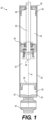
- damper assembly 20 which may be used as a part of a suspension in a vehicle, such as a passenger car or truck.
- the damper assembly 20 of the present disclosure is shown as a monotube damper. However, the principles of the present disclosure may be used with other types of dampers, such as in a twin-tube damper.
- the damper assembly 20 of the present disclosure provides a unique solution for the implementation of a Frequency Adaptive Orifice (FAO) within a piston valve assembly.
- FEO Frequency Adaptive Orifice
- the damper assembly 20 includes a housing 22 having a tubular shape extending along a center axis A between a first end 24 and a second end 26 and defining a main compartment 30, 32, 34 therein.
- the damper assembly 20 also includes a gas cup 28 disposed in the main compartment 30, 32, 34 in sealing engagement with the housing 22 and slidable along the center axis A to divide the main compartment 30, 32, 34 into a gas compartment 30 for containing a gas and a fluid compartment 32, 34.
- the gas compartment 30 extends between the first end 24 and the gas cup 28, and the fluid compartment 32, 34 extends between the gas cup 28 and the second end 26.
- the damper assembly 20 also includes a damper rod 36 that extends along the center axis A.
- the damper rod 36 includes a rod end 38 located inside of the fluid compartment 32, 34.
- a piston 40 is attached to the damper rod 36 adjacent to the rod end 38, and configured to move with the damper rod 36 along the center axis A through the housing 22.
- the piston 40 divides the fluid compartment 32, 34 into a compression chamber 32 and a rebound chamber 34.
- the compression chamber 32 extends between the piston 40 and the gas cup 28, and the rebound chamber 34 extends between the second end 26 and the piston 40.
- a first closure 42 seals the gas compartment 30 at the first end 24 of the housing 22.
- a damper mount 44 is attached to the first closure 42 and configured to attach the damper assembly 20 to a body of a vehicle (not shown).
- the damper assembly 20 of the present disclosure may be used in other configurations and/or orientations.
- the damper mount 44 may connect the housing 22 of the damper assembly 20 to a chassis component of the vehicle 10.
- the damper assembly 20 also includes a second closure 46 disposed adjacent to the second end 26 of the housing 22 to enclose the rebound chamber 34.
- the second closure 46 defines a bore 48 for the damper rod 36 to pass through.
- the second closure 46 may provide a fluid-tight seal with the damper rod 36 to prevent fluid from leaking out of the rebound chamber 34.
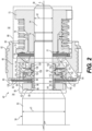
- Fig. 2 shows an enlarged cross-sectional perspective view of the piston 40 of the present disclosure.
- the damper rod 36 includes a rod body 50 having a cylindrical shape with a first diameter d1, a rod shoulder 52 spaced apart from and facing toward the rod end 38.
- the damper rod 36 also includes a rod extension 54 extending from the rod shoulder 52 to the rod end 38 and having a generally cylindrical shape with a second diameter d2 smaller than the first diameter d1.
- the piston 40 includes a piston body 60 disposed around the rod extension 54.
- the piston body 60 includes an annular seal 62 of resilient material configured to seal against an inner surface of the housing 22 (not shown in Fig. 2 ).
- the piston body 60 defines a rebound passage 64 in fluid communication with the rebound chamber 34 and providing a path for fluid flow to the compression chamber 32.
- the piston body 60 also defines a compression passage 66 in fluid communication with the compression chamber 32 and providing a path for fluid flow to the rebound chamber 34.
- the piston 40 also includes a rebound valve assembly 68 configured to regulate fluid flow from the rebound chamber 34 to the compression chamber 32 during a rebound stroke, with the damper rod 36 pulling the piston 40 toward the second end 26.
- the rebound valve assembly 68 includes a rebound disc stack 70 including a plurality of discs covering an end of the rebound passage 64 opposite from the rebound chamber 34 and configured to deflect away from the rebound passage 64 in response to a pressure differential thereacross, and to thereby regulate fluid flow through the rebound passage 64 and into the compression chamber 32.
- the rebound valve assembly 68 also includes a shoulder nut 72 and a spring seat 74, with a spring 76 extending therebetween to bias the rebound disc stack 70 to cover the rebound passage 64.
- a rebound spacer disc 77 having a disc shape is disposed around the rod extension 54 between the rebound disc stack 70 and the shoulder nut 72.
- the rebound spacer disc 77 has a smaller diameter than the rebound disc stack 70 for supporting an inner region of the rebound disc stack 70 while allowing a radially outer portion of the rebound disc stack 70 to deflect axially away from the piston body 60 for regulating the fluid flow through the rebound passage 64.
- the piston 40 also includes a compression valve assembly 80 configured to regulate fluid flow from the compression chamber 32 to the rebound chamber 34 during a compression stroke, with the damper rod 36 pushing the piston 40 toward the first end 24 of the housing 22.
- the compression valve assembly 80 includes a compression disc stack 82 having a plurality of discs covering an end of the compression passage 66 opposite from the compression chamber 32.
- the compression disc stack 82 is configured to deflect away from the compression passage 66 in response to a pressure differential thereacross, and to thereby regulate fluid flow through the compression passage 66 and into the rebound chamber 34.
- the compression valve assembly 80 includes a compression disc retainer 84 having a ring shape disposed about the rod extension 54 between the rod shoulder 52 and the compression disc stack 82.
- the compression valve assembly 80 also includes a first spacer disc 86 disposed around the rod extension 54 adjacent to the compression disc stack 82 and between the compression disc retainer 84 and the compression disc stack 82.
- the first spacer disc 86 has a smaller diameter than the compression disc stack 82 for supporting an inner region of the compression disc stack 82 while allowing a radially outer portion of the compression disc stack 82 to deflect axially away from the piston body 60 for regulating the fluid flow through the compression passage 66.
- the compression valve assembly 80 also includes a second spacer disc 88 having a disc shape disposed around the rod extension 54 adjacent to the compression disc stack 82 and opposite from the first spacer disc 86.
- the thickness of the second spacer disc 88 may define a preload of the compression disc stack 82.
- the compression disc retainer 84 and the rod extension 54 together define a lower chamber 85 adjacent to the rod shoulder 52.
- the piston 40 also includes a frequency-adaptive orifice (FAO) valve assembly 90 that includes a guiding sleeve 92 disposed around the rod extension 54.
- the guiding sleeve 92 includes a proximal tubular portion 94 having a tubular shape disposed around and coaxial with the rod extension 54 and adjacent to the rod shoulder 52.
- the proximal tubular portion 94 has a first inner surface 96 that is spaced apart from the rod extension 54 to define a first balance passage 98 therebetween.
- the guiding sleeve 92 also includes a disc-shaped portion 100 extending radially outwardly from an end of the proximal tubular portion 94 spaced apart from the rod shoulder 52.
- the disc-shaped portion 100 is disposed annularly about the proximal tubular portion 94 of the guiding sleeve 92.
- the guiding sleeve 92 also includes a distal tubular portion 102 having a tubular shape and extending axially from the disc-shaped portion 100 away from the rod shoulder 52.
- the distal tubular portion 102 is disposed coaxially with and tightly against the rod extension 54, with little to no space therebetween.
- the guiding sleeve 92 further defines a second balance passage 104 extending radially outwardly from the first balance passage 98 and axially through the disc-shaped portion 100.
- the compression valve assembly 80 is disposed around the proximal tubular portion 94 of the guiding sleeve 92, with the second spacer disc 88 separating the compression disc stack 82 from the disc-shaped portion 100.
- the distal tubular portion 102 of the guiding sleeve 92 further defines a plurality of indentations 106 in an outer surface thereof.
- the FAO valve assembly 90 also includes a tappet 110 having a ring shape disposed around and engaging the guiding sleeve 92 and configured to translate relative to the piston body 60 in an axial direction.
- the tappet 110 includes an inner tubular portion 112 disposed around the distal tubular portion 102 of the guiding sleeve 92 and configured to slide therealong.
- the tappet 110 further includes a flange portion 114 having an annular shape extending radially outwardly from the inner tubular portion 112.
- the tappet 110 also includes an outer tubular portion 116 extending annularly around the flange portion 114 and axially toward the rod shoulder 52.
- the outer tubular portion 116 of the tappet 110 is disposed annularly around the disc-shaped portion 100 of the guiding sleeve 92 and is configured to slide therealong.
- the tappet 110 defines a tappet chamber 118 surrounded by the outer tubular portion 116 and extending between the flange portion 114 and the disc-shaped portion 100 of the guiding sleeve 92.
- the piston body 60 defines an FAO chamber 120 having a generally cylindrical shape coaxially surrounding the rod extension 54, with a lower wall 122 facing toward the rod shoulder 52.
- the guiding sleeve 92 and the tappet 110 are disposed within the FAO chamber 120.
- the piston body 60 also defines an inner bore 124 having a cylindrical shape coaxially surrounding the rod extension 54 extending in an axial direction from the lower wall 122 away from the rod shoulder 52.
- the inner bore 124 is configured to receive an end of the distal tubular portion 102 of the guiding sleeve 92 for locating the guiding sleeve 92 with the piston body 60.
- the piston body 60 also defines a first FAO passage 126 providing fluid communication between the compression passage 66 and the FAO chamber 120.
- the piston body 60 further defines a second FAO passage 128 providing fluid communication between the rebound passage 64 and the FAO chamber 120.
- the piston body 60 also includes an annular protrusion 130 extending in an axial direction from the lower wall 122 and into the FAO chamber 120 adjacent to and radially outwardly from the second FAO passage 128.
- the FAO valve assembly 90 further includes an FAO cover member 132 configured to selectively cover the second FAO passage 128 to block fluid flow therethrough.
- the FAO cover member 132 may be formed as a disc that is disposed annularly around the distal tubular portion 102 of the guiding sleeve 92 abutting the annular protrusion 130, as shown in Fig. 2 .
- the FAO cover member 132 could have a different shape or configuration.
- the FAO valve assembly 90 also includes an FAO spacer 134 having a ring shape disposed annularly around the distal tubular portion 102 of the guiding sleeve 92 and between the tappet 110 and the FAO cover member 132.
- the distal tubular portion 102 of the guiding sleeve 92 includes an outer surface defining a first seal slot 136 holding a first O-ring seal 138 that seals against an inner surface of the inner tubular portion 112 of the tappet 110.
- the disc-shaped portion 100 of the guiding sleeve 92 includes an outer surface defining a second seal slot 140 holding a second O-ring seal 142 that seals against an inner surface of the outer tubular portion 116 of the tappet 110.
- the FAO valve assembly 90 also includes a valve control disc 144 having an annular shape and disposed adjacent to the rod shoulder 52 and between the rod shoulder 52 and the compression disc retainer 84. As best shown on Fig. 3 , valve control disc 144 defines a control orifice 146 that extends at least partially through the valve control disc 144 in a radial direction from an outer edge thereof for providing fluid communication between the rebound chamber 34 and the lower chamber 85.
- the first balance passage 98 and the second balance passage 104 together provide fluid communication between the lower chamber 85 and the tappet chamber 118 to pressurize the tappet chamber 118 during a rebound stroke.
- This pressurization of the tappet chamber 118 causes the tappet 110 to be biased away from the rod shoulder 52 and toward the FAO cover member 132, thereby causing the FAO cover member 132 to cover the second FAO passage 128 and to prevent fluid flow therethrough.
- the FAO cover member 132 is supported by the tappet 110 that preloads the FAO cover member 132 depending on a volume of fluid, such as oil, and pressure in the tappet chamber 118.
- the tappet chamber 118 is supplied with oil from the rebound chamber 34 via the valve control disc 144, which is located between the rod shoulder 52 and the compression disc retainer 84.
- the FAO cover member 132 works in both directions, and thus provide extended functionality in both rebound and compression strokes.
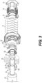
- Fig. 3 shows an exploded view of the piston 40 including the FAO valve assembly 90.
- Fig. 4 shows a perspective view of the guiding sleeve 92.
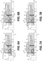
- Fig. 5A shows an enlarged cross-sectional fragmentary view of the piston 40, showing fluid flow therethrough during application of a low-frequency excitation, below a predetermined frequency.
- the throttling effect of the control orifice 146 is low, so the tappet chamber 118 surrounded is effectively fed with fluid through the valve control disc 144 and the balance passages 98, 104.
- Pressure in the tappet chamber 118 is relatively high, and the tappet 110 is forced against the FAO cover member 132, thus increasing its preload.
- Fig. 5B shows an enlarged cross-sectional fragmentary view of the piston 40, showing fluid flow therethrough with the damper assembly 20 during application of a high-frequency excitation, above the predetermined frequency.
- the FAO cover member 132 throttles the flow of fluid, and so there is high pressure drop between the rebound chamber 34 and the tappet chamber 118. Pressure acting on the tappet 110, and thereby preload of the FAO cover member 132 is relatively small, making the FAO valve assembly 90 less stiff.
- Fig. 6A shows an enlarged cross-sectional fragmentary view of the piston 40 during a rebound stroke, in a low-frequency state, and showing fluid flow therethrough.
- Fig. 6A shows the FAO valve assembly 90 in an inactive state, with the FAO cover member 132 blocking fluid flow through the second FAO passage 128.
- the FAO cover member 132 may be biased to block the second FAO passage 128 during the rebound stroke, preventing fluid flow therethrough.
- the tappet 110 may press the FAO cover member 132 to block the second FAO passage 128 by fluid pressure in the tappet chamber 118 being greater than a fluid pressure in the FAO chamber 120.
- FIG. 6B shows an enlarged cross-sectional fragmentary view of the piston 40 during a rebound stroke, in a high-frequency state, and showing fluid flow therethrough.
- the FAO valve assembly 90 may allow fluid flow through one or more FAO passages 126, 128 in response to application of a high-frequency excitation above a predetermined frequency.
- the predetermined frequency may also be called a cutoff frequency.
- the FAO valve assembly 90 provides a rebound bypass fluid path from the rebound chamber 34 to the compression chamber 32, bypassing the rebound valve assembly 68, in response to a high-frequency rebound excitation applied to the piston 40.
- the FAO valve assembly thereby reduces the force generated by the damper assembly 20 in response to the high-frequency rebound excitation by allowing fluid flow through the rebound bypass fluid path.
- the FAO valve assembly 90 also blocks the rebound bypass fluid path in response to a low-frequency rebound excitation applied to the piston 40, as shown in Fig. 6A .
- the rebound bypass fluid path through the FAO valve assembly 90 is illustrated in Fig. 6B and includes the FAO passages 126, 128. More specifically, the rebound bypass fluid path includes fluid flow from the rebound chamber 34, through the rebound passage 64 and the second FAO passage 128, past the FAO cover member 132 and into the FAO chamber 120. The rebound bypass fluid path then includes the fluid flowing from the FAO chamber 120 through the first FAO passage 126 and the compression passage 66 and then to the compression chamber 32. In this case, rebound damping force is decreased.
- Fig. 7A shows an enlarged cross-sectional fragmentary view of the piston 40 during a compression stroke, in a low-frequency state, and showing fluid flow therethrough.
- Fig. 7A shows the FAO valve assembly 90 in an inactive state, with the FAO cover member 132 blocking fluid flow through the second FAO passage 128.
- the FAO cover member 132 may be biased to block the second FAO passage 128 during the compression stroke, preventing fluid flow therethrough.
- the FAO cover member 132 may be deflected to block the second FAO passage 128 by fluid pressure in the FAO chamber 120 being greater than a fluid pressure in the second FAO passage 128.
- Fig. 7B shows an enlarged cross-sectional fragmentary view of the piston 40 during a compression stroke, in a high-frequency state, and showing fluid flow therethrough.
- the FAO valve assembly 90 provides compression bypass fluid path from the compression chamber 32 to the rebound chamber 34, bypassing the compression valve assembly 80, in response to a high-frequency compression excitation applied to the piston 40.
- the FAO valve assembly thereby reduces the force generated by the damper assembly 20 in response to a high-frequency compression excitation by allowing fluid flow through the compression bypass fluid path.
- the FAO valve assembly 90 also blocks the compression bypass fluid path in response to a low-frequency compression excitation, as shown in Fig. 7A .
- the compression bypass fluid path through the FAO valve assembly 90 is illustrated in Fig. 7B and includes the FAO passages 126, 128. More specifically, the compression bypass fluid path includes fluid flow from the compression chamber 32, through the compression passage 66 and the first FAO passage 126, and into the FAO chamber 120. The compression bypass fluid path then includes the fluid flowing from the FAO chamber 120, past the FAO cover member 132, through the second FAO passage 128 and the rebound passage 64, and then to the rebound chamber 34.
- the indentations 106 in the distal tubular portion 102 of the guiding sleeve 92 may provide a path for fluid flow from the FAO chamber 120 and to the second FAO passage 128 when the FAO cover member 132 is deflected toward the piston body 60, as shown in Fig. 7B .
- the operating characteristics of the FAO valve assembly 90 can be adjusted by one or more of: oil flow area of the control orifice 146 (e.g. number and width of slots), a number and thickness of working discs comprising the FAO cover member 132, a number and/or cross-sectional area of the first FAO passages 126 and/or second FAO passages 128 in the piston body 60, and/or a thickness of the FAO spacer 134 that defines a nominal working disc preload of the FAO cover member 132.
- Fig. 8 shows a first graph 200 illustrating rebound force vs. velocity characteristics of a damper with the frequency-adaptive orifice valve of the present disclosure under standard and high-frequency conditions.
- the first graph 200 includes a first plot 202 showing force vs. velocity for the damper under low-frequency excitation conditions.
- the first graph 200 also includes a second plot 204 showing force vs. velocity for the damper under high-frequency excitation conditions.
- Fig. 9 shows a second graph 250 with a plot 252 showing rebound force vs. stroking frequency of a damper with the frequency-adaptive orifice valve of the present disclosure and at constant velocity.
- the FAO valve assembly 90 may be adjusted or tuned to provide any predetermined cutoff frequency ranging from about 2.0 Hz to about 12 Hz.
- the FAO valve assembly 90 of the present disclosure is shown and described as located within a compression side of the piston 40. However, other configurations are possible. For example, the FAO valve assembly 90 may be located on the rebound side of the piston 40 or on both sides of the piston 40, simultaneously.
- an FAO valve may be disposed within a compression valve assembly (i.e. a base valve assembly) of a twin-tube damper assembly.
- a twin-tube damper may include an inner tube disposed within the housing 22 and defining a main chamber within the inner tube and an exterior chamber between the inner tube and the housing 22, wherein the piston divides the main chamber into a compression chamber and a rebound chamber.
- a twin-tube damper may also include a base assembly including a base valve configured to regulate fluid flow between the main chamber and the exterior chamber.
- the base assembly may include the body that defines the FAO passage.
- a damper assembly includes a housing having a tubular shape extending along a center axis; a piston movable through the housing along the center axis; a body defining a frequency-adaptive orifice (FAO) passage providing fluid communication between a first chamber and a second chamber; and an FAO valve assembly having an FAO cover member configured to selectively cover the FAO passage to block fluid flow therethrough in response to application of a low-frequency excitation below a predetermined frequency, the FAO valve assembly further configured to allow fluid flow through the FAO passage in response to application of a high-frequency excitation above the predetermined frequency.
- FEO frequency-adaptive orifice
- the FAO valve assembly further comprises a tappet configured to translate relative to the body to bias the FAO cover member to selectively cover the FAO passage in response to the application of the low-frequency excitation in an at least one of a compression direction or a rebound direction opposite the compression direction.
- the housing defines a main chamber
- the piston divides the main chamber into a compression chamber and a rebound chamber
- the first chamber includes the compression chamber
- the second chamber includes the rebound chamber.
- the piston includes a piston body and the piston body is the body defining the FAO passage.
- the tappet is configured to bias the FAO cover member to selectively cover the FAO passage in response to the application of the low-frequency excitation in the rebound direction.
- the piston body defines an FAO chamber with the tappet disposed therein; and the FAO chamber is in fluid communication with the compression chamber.
- the piston body defines a rebound passage in fluid communication with the rebound chamber; the piston further comprises a rebound valve assembly including a rebound disc stack covering an end of the rebound passage to regulate fluid flow from the rebound chamber to the compression chamber during a rebound stroke; and the FAO passage extends between the rebound passage and the FAO chamber to provide fluid communication therebetween.
- the damper assembly further includes a damper rod extending along the center axis and including a rod end located within the main chamber; the piston is attached to the damper rod adjacent to the rod end; the piston further comprises a guiding sleeve disposed about the damper rod; and the tappet has ring shape disposed around and engaging the guiding sleeve.
- the piston further comprises a compression valve assembly configured to regulate fluid flow from the compression chamber to the rebound chamber during a compression stroke, the compression valve assembly including a compression disc stack disposed annularly around the guiding sleeve.
- the guiding sleeve includes a distal tubular portion disposed coaxially with and tightly against the damper rod; and the tappet is disposed around the distal tubular portion and is configured to slide therealong.
- the distal tubular portion of the guiding sleeve includes an outer surface defining a first seal slot receiving a first O-ring seal for sealing against an inner surface of the tappet.
- the guiding sleeve further includes a disc-shaped portion that extends annularly around the damper rod and radially outwardly from the distal tubular portion;
- the tappet includes an inner tubular portion disposed around the distal tubular portion of the guiding sleeve and configured to slide therealong;
- the tappet further includes a flange portion and an outer tubular portion, the flange portion having an annular shape extending radially outwardly from the inner tubular portion, the outer tubular portion extending annularly around the flange portion; and the outer tubular portion of the tappet is disposed annularly around the disc-shaped portion of the guiding sleeve and configured to slide therealong.
- the tappet and the guiding sleeve together define a tappet chamber extending between the flange portion of the tappet and the disc-shaped portion of the guiding sleeve; and the tappet chamber is in fluid communication with the rebound chamber via a balance passage.
- the disc-shaped portion of the guiding sleeve includes an outer surface defining a second seal slot with a second O-ring seal disposed therein and sealing against an inner surface of the outer tubular portion of the tappet.
- the tappet defines, at least in part, a tappet chamber; wherein the tappet chamber is in fluid communication with the rebound chamber via a balance passage; and the guiding sleeve defines, at least in part, the balance passage.
- the guiding sleeve includes a proximal tubular portion having a tubular shape disposed around the damper rod and spaced apart therefrom to define, at least in part, the balance passage therebetween.
- the tappet defines, at least in part, a tappet chamber; the tappet chamber is in fluid communication with the rebound chamber via a balance passage; and the FAO valve assembly further comprises a control orifice configured to restrict fluid flow between the rebound chamber and the tappet chamber.
- the damper assembly further comprises a damper rod extending along the center axis and including a rod end located within the main chamber; the piston is attached to the damper rod adjacent to the rod end; the damper rod includes a rod body having a first diameter, a rod shoulder spaced apart from and facing toward the rod end, and a rod extension extending from the rod shoulder to the rod end and having a second diameter smaller than the first diameter; and the FAO valve assembly further comprises a valve control disc disposed around the rod extension and defining, at least in part, the control orifice.
- a piston for a damper assembly includes: a piston body defining a frequency-adaptive orifice (FAO) passage for providing fluid communication between a compression chamber and a rebound chamber; an FAO valve assembly having an FAO cover member configured to selectively cover the FAO passage to block fluid flow therethrough in response to application of a low-frequency excitation below a predetermined frequency, the FAO valve assembly further configured to allow fluid flow through the FAO passage in response to application of a high-frequency excitation above the predetermined frequency; and the FAO valve assembly further includes a tappet configured to translate relative to the piston body to bias the FAO cover member to selectively cover the FAO passage in response to the application of the low-frequency excitation in an at least one of a compression direction or a rebound direction opposite the compression direction.
- FEO frequency-adaptive orifice
- the piston further includes a guiding sleeve; and the tappet has ring shape disposed around and engaging the guiding sleeve.
- the guiding sleeve includes a distal tubular portion having a tubular shape; and the tappet is disposed around the distal tubular portion and is configured to slide therealong.
- the guiding sleeve further includes a disc-shaped portion that extends radially outwardly from the distal tubular portion;
- the tappet includes an inner tubular portion disposed around the distal tubular portion of the guiding sleeve and configured to slide therealong;
- the tappet further includes a flange portion and an outer tubular portion, the flange portion having an annular shape extending radially outwardly from the inner tubular portion, the outer tubular portion extending annularly around the flange portion; and the outer tubular portion of the tappet is disposed annularly around the disc-shaped portion of the guiding sleeve and configured to slide therealong.
Landscapes
- Engineering & Computer Science (AREA)
- General Engineering & Computer Science (AREA)
- Physics & Mathematics (AREA)
- Fluid Mechanics (AREA)
- Mechanical Engineering (AREA)
- Fluid-Damping Devices (AREA)
Applications Claiming Priority (2)
| Application Number | Priority Date | Filing Date | Title |
|---|---|---|---|
| CN202210267856.XA CN114738422B (zh) | 2022-03-18 | 2022-03-18 | 阻尼器组件及用于阻尼器组件的活塞 |
| US17/723,421 US20230296157A1 (en) | 2022-03-18 | 2022-04-18 | Damper assembly with frequency adaptive orifice |
Publications (1)
| Publication Number | Publication Date |
|---|---|
| EP4246010A1 true EP4246010A1 (fr) | 2023-09-20 |
Family
ID=85641006
Family Applications (1)
| Application Number | Title | Priority Date | Filing Date |
|---|---|---|---|
| EP23161669.9A Pending EP4246010A1 (fr) | 2022-03-18 | 2023-03-14 | Ensemble amortisseur à orifice adaptatif en fréquence |
Country Status (1)
| Country | Link |
|---|---|
| EP (1) | EP4246010A1 (fr) |
Citations (4)
| Publication number | Priority date | Publication date | Assignee | Title |
|---|---|---|---|---|
| US5706920A (en) | 1996-08-15 | 1998-01-13 | General Motors Corporation | Monotube damper |
| US9534653B2 (en) * | 2014-03-28 | 2017-01-03 | Mando Corporation | Piston assembly for shock absorber |
| US20200215864A1 (en) * | 2019-01-04 | 2020-07-09 | Kyb Europe Gmbh, Sucursal En Navarra | Shock Absorber with Hydraulic Load Regulation Simultaneously Depending on Speed and Frequency |
| US10774895B2 (en) * | 2016-01-01 | 2020-09-15 | Plush Ride Gmbh | Clamped frequency dependent piston assembly |
-
2023
- 2023-03-14 EP EP23161669.9A patent/EP4246010A1/fr active Pending
Patent Citations (4)
| Publication number | Priority date | Publication date | Assignee | Title |
|---|---|---|---|---|
| US5706920A (en) | 1996-08-15 | 1998-01-13 | General Motors Corporation | Monotube damper |
| US9534653B2 (en) * | 2014-03-28 | 2017-01-03 | Mando Corporation | Piston assembly for shock absorber |
| US10774895B2 (en) * | 2016-01-01 | 2020-09-15 | Plush Ride Gmbh | Clamped frequency dependent piston assembly |
| US20200215864A1 (en) * | 2019-01-04 | 2020-07-09 | Kyb Europe Gmbh, Sucursal En Navarra | Shock Absorber with Hydraulic Load Regulation Simultaneously Depending on Speed and Frequency |
Similar Documents
| Publication | Publication Date | Title |
|---|---|---|
| US6918473B2 (en) | Stroke dependent bypass | |
| US8256586B2 (en) | Shock absorber having a continuously variable valve with base line valving | |
| CN107091294B (zh) | 具有用于孔口通路的止回盘的减振器 | |
| US11326663B2 (en) | Damper assembly and a piston for a damper assembly | |
| CN111902654B (zh) | 具有阀预载限制器的阻尼器 | |
| US10989268B2 (en) | Damper with hydraulic end stop | |
| WO2005036016A1 (fr) | Support supplementaire destine a un disque de soupape | |
| US6230858B1 (en) | Internally slotted orifice disc for low speed control in automotive dampers | |
| WO2005033546A1 (fr) | Zone d'appui d'appoint pour disque de soupape | |
| CN111971487B (zh) | 具有浮动活塞泄放通道的阻尼器 | |
| WO2020069440A1 (fr) | Amortisseur à disque flottant souple | |
| EP1664581B1 (fr) | Amortisseur | |
| CN112360913B (zh) | 液压阻尼器和用于液压阻尼器组件的活塞 | |
| EP4246010A1 (fr) | Ensemble amortisseur à orifice adaptatif en fréquence | |
| US20230296157A1 (en) | Damper assembly with frequency adaptive orifice | |
| EP3967899A1 (fr) | Ensemble d'amortisseur télescopique | |
| EP4421348A1 (fr) | Ensemble amortisseur avec soupape serrée dépendant de la fréquence | |
| US20240288047A1 (en) | Damper assembly with clamped frequency dependent valve |
Legal Events
| Date | Code | Title | Description |
|---|---|---|---|
| PUAI | Public reference made under article 153(3) epc to a published international application that has entered the european phase |
Free format text: ORIGINAL CODE: 0009012 |
|
| STAA | Information on the status of an ep patent application or granted ep patent |
Free format text: STATUS: THE APPLICATION HAS BEEN PUBLISHED |
|
| AK | Designated contracting states |
Kind code of ref document: A1 Designated state(s): AL AT BE BG CH CY CZ DE DK EE ES FI FR GB GR HR HU IE IS IT LI LT LU LV MC ME MK MT NL NO PL PT RO RS SE SI SK SM TR |
|
| STAA | Information on the status of an ep patent application or granted ep patent |
Free format text: STATUS: REQUEST FOR EXAMINATION WAS MADE |
|
| 17P | Request for examination filed |
Effective date: 20240320 |
|
| RBV | Designated contracting states (corrected) |
Designated state(s): AL AT BE BG CH CY CZ DE DK EE ES FI FR GB GR HR HU IE IS IT LI LT LU LV MC ME MK MT NL NO PL PT RO RS SE SI SK SM TR |