EP4245665A2 - Gekapselte lagerblockkonstruktion für einstellbare hakenverschlüsse - Google Patents
Gekapselte lagerblockkonstruktion für einstellbare hakenverschlüsse Download PDFInfo
- Publication number
- EP4245665A2 EP4245665A2 EP23186383.8A EP23186383A EP4245665A2 EP 4245665 A2 EP4245665 A2 EP 4245665A2 EP 23186383 A EP23186383 A EP 23186383A EP 4245665 A2 EP4245665 A2 EP 4245665A2
- Authority
- EP
- European Patent Office
- Prior art keywords
- hook body
- hook
- boss
- latch mechanism
- bearing block
- Prior art date
- Legal status (The legal status is an assumption and is not a legal conclusion. Google has not performed a legal analysis and makes no representation as to the accuracy of the status listed.)
- Pending
Links
Images



Classifications
-
- E—FIXED CONSTRUCTIONS
- E05—LOCKS; KEYS; WINDOW OR DOOR FITTINGS; SAFES
- E05C—BOLTS OR FASTENING DEVICES FOR WINGS, SPECIALLY FOR DOORS OR WINDOWS
- E05C19/00—Other devices specially designed for securing wings, e.g. with suction cups
- E05C19/10—Hook fastenings; Fastenings in which a link engages a fixed hook-like member
- E05C19/12—Hook fastenings; Fastenings in which a link engages a fixed hook-like member pivotally mounted around an axis
- E05C19/14—Hook fastenings; Fastenings in which a link engages a fixed hook-like member pivotally mounted around an axis with toggle action
- E05C19/145—Hook fastenings; Fastenings in which a link engages a fixed hook-like member pivotally mounted around an axis with toggle action flush
-
- B—PERFORMING OPERATIONS; TRANSPORTING
- B64—AIRCRAFT; AVIATION; COSMONAUTICS
- B64D—EQUIPMENT FOR FITTING IN OR TO AIRCRAFT; FLIGHT SUITS; PARACHUTES; ARRANGEMENT OR MOUNTING OF POWER PLANTS OR PROPULSION TRANSMISSIONS IN AIRCRAFT
- B64D29/00—Power-plant nacelles, fairings or cowlings
- B64D29/06—Attaching of nacelles, fairings or cowlings
-
- E—FIXED CONSTRUCTIONS
- E05—LOCKS; KEYS; WINDOW OR DOOR FITTINGS; SAFES
- E05B—LOCKS; ACCESSORIES THEREFOR; HANDCUFFS
- E05B63/00—Locks or fastenings with special structural characteristics
- E05B63/0056—Locks with adjustable or exchangeable lock parts
-
- E—FIXED CONSTRUCTIONS
- E05—LOCKS; KEYS; WINDOW OR DOOR FITTINGS; SAFES
- E05B—LOCKS; ACCESSORIES THEREFOR; HANDCUFFS
- E05B63/00—Locks or fastenings with special structural characteristics
- E05B63/06—Locks or fastenings with special structural characteristics with lengthwise-adjustable bolts ; with adjustable backset, i.e. distance from door edge
-
- Y—GENERAL TAGGING OF NEW TECHNOLOGICAL DEVELOPMENTS; GENERAL TAGGING OF CROSS-SECTIONAL TECHNOLOGIES SPANNING OVER SEVERAL SECTIONS OF THE IPC; TECHNICAL SUBJECTS COVERED BY FORMER USPC CROSS-REFERENCE ART COLLECTIONS [XRACs] AND DIGESTS
- Y10—TECHNICAL SUBJECTS COVERED BY FORMER USPC
- Y10T—TECHNICAL SUBJECTS COVERED BY FORMER US CLASSIFICATION
- Y10T292/00—Closure fasteners
- Y10T292/08—Bolts
- Y10T292/0911—Hooked end
- Y10T292/0913—Sliding and swinging
- Y10T292/0914—Operating means
- Y10T292/0917—Lever
Definitions
- the present disclosure relates generally to latch mechanisms and, more particularly, to aircraft latch mechanisms exhibiting anti-rotation and alignment features.
- latching mechanisms exist for use in aircraft as aircraft have many components, such as fuselage panels, including cowlings and the like, which must be opened and closed securely.
- tension latches mounted on a first panel are typically configured to cinch to a keeper on a second panel to hold the first panel, which may be a moveable panel, closed relative to the second panel.
- Other latches include sliding toggle linkages to minimize the kinematic envelope of the latch. These linkages rotate around a mounting pin to produce the latch reach.
- the complexity of certain aircraft latches makes them relatively large and heavy, which is disfavored on aircraft. Accordingly, it is desirable to provide a latch having a reduced size and weight, but that exhibits the strength and other features of larger and heavier latches.
- a latch mechanism is disclosed according to an aspect of the invention.
- the latch mechanism includes a hook body, the hook body having a hook body load bearing plate; a hook mechanism, the hook mechanism having a hook with a threaded shaft, the shaft defining a longitudinal axis with respect to the hook body; an adjustment mechanism configured to adjust an axial position of the hook with respect to the hook body; and a bearing block, the bearing block having a block load bearing plate disposed between the adjustment mechanism and the hook body load bearing plate, the bearing block including a first boss configured for engagement with the adjustment mechanism, a second boss configured for engagement with the hook body plate aperture, an inner diameter hole that allows the hook shaft threads to engage with the adjustment mechanism but provides suitable clearance within the second boss inner diameter to prevent the hook shaft threads from bearing out as required in Aerospace design.
- the bearing block provides axial alignment for multiple structural components as the bearing block load bearing plate disposed between the adjustment mechanism and the hook body load bearing plate with included hollowed out bosses mates the aforementioned component parts providing axial alignment of the hook shaft, hook body plate aperture, and adjustment mechanism (nut) about the center of aperture of the bearing block.
- the hook body includes a plate aperture that extends in an axial direction through the hook body load bearing plate.
- the bearing block includes a second boss configured for engagement with the plate aperture.
- the second boss defines a second boss outer diameter and the plate aperture defines a plate aperture inner diameter, the plate aperture inner diameter being within a press-fit tolerance of the second boss outer diameter.
- the press-fit tolerance is between one or two thousandths of an inch ( ⁇ 25 to 50 microns).
- the bearing block first boss is configured to engage a recess within the adjustment mechanism.
- the adjustment mechanism includes an adjustment nut configured for threaded engagement with the hook shank threads.
- the bearing block includes a second boss, the second boss defining a second boss inner diameter, and wherein the hook shank threads defines an outer diameter, the hook shank thread outer diameter having sufficient clearance within the second boss inner diameter as to prevent the hook shank threads from bearing on the smooth second boss inner diameter as is a requirement in Aerospace design.
- the adjustment mechanism and the block load bearing plate are configured to provide a lock mechanism, the lock mechanism being configured to prevent rotation of the adjustment mechanism about the longitudinal axis.
- a latch mechanism for an aircraft panel includes a hook body, the hook body including a plurality of longitudinal members, each of the plurality of longitudinal members extending in an axial direction with respect to the hook body, the hook body further having a hook body load bearing plate connected to the plurality of longitudinal members and being oriented perpendicular to the axial direction; a hook mechanism, the hook mechanism having a hook with a threaded shaft, the shaft extending in the axial direction with respect to the hook body; an adjustment mechanism configured to adjust an axial position of the hook with respect to the hook body; and bearing block, the bearing block having a load bearing plate disposed between the adjustment mechanism and the hook body load bearing plate with included hollowed out bosses that allows for axial alignment of the hook shaft, hook body plate aperture, and adjustment mechanism(nut) about the center of aperture of the bearing block.
- the hook body includes a plate aperture that extends in the axial direction through the hook body load bearing plate.
- the bearing block includes a boss (e.g., a first boss) configured for engagement with the plate aperture.
- the first boss defines a first boss outer diameter and the plate aperture defines a plate aperture inner diameter, the plate aperture inner diameter being within a press-fit tolerance of the first boss outer diameter.
- the press-fit tolerance is between one or two thousandths of an inch ( ⁇ 25 to 50 microns).
- the bearing block includes a boss (e.g., a second boss) configured for engagement with the adjustment mechanism.
- the adjustment mechanism includes an adjustment nut configured for threaded engagement with the shaft.
- the first boss defines a first boss inner diameter and the shaft defines a shaft outer diameter, the shaft outer diameter being within a sliding-fit tolerance of the first boss inner diameter.
- the sliding tolerance is between five and ten thousandths of an inch ( ⁇ 125 to 250 microns).
- the adjustment mechanism and the block load bearing plate are configured to provide a lock mechanism, the lock mechanism being configured to prevent rotation of the adjustment mechanism about the axial direction.
- references to "a,” “an” or “the” may include one or more than one and that reference to an item in the singular may also include the item in the plural. Further, all ranges may include upper and lower values and all ranges and ratio limits disclosed herein may be combined.
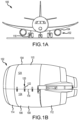
- FIGS. 1A and 1B provide schematic illustrations of an aircraft 100 having and an aircraft propulsion system 102, in accordance with various embodiments.
- the aircraft propulsion system 102 may include various systems, such as, for example, a gas turbine engine system housed within a nacelle 104.
- the nacelle 104 typically comprises a plurality of aerodynamic panels, such as, for example, one or more core cowl panels 106 ( e.g. , a first core cowl panel 108 and a second core cowl panel 110), one or more thrust reverser panels 112 and one or more fan cowl panels 114, each of which may be removable, hinged, or otherwise configurable to enable access to internal components of the aircraft 100 or the aircraft propulsion system 102.
- the aircraft 100 may also include various additional systems, such as, for example, one or more landing gear 116, which generally support the aircraft 100 when the aircraft 100 is not flying, allowing the aircraft 100 to taxi, takeoff or land without damage.
- the first core cowl panel 108 and the second core cowl panel 110 are coupled, in various embodiments, along a seam 118 by a latch mechanism 120 (or a plurality of latch mechanisms).
- a latch handle 122 of the latch mechanism 120 may sit relatively flush or may be recessed within an aerodynamic panel surface 124 defined by the first core cowl panel 108 and the second core cowl panel 110.
- the latch handle 122 of the latch mechanism 120 may protrude above or outside of the aerodynamic panel surface 124.
- latch mechanism 120 is presented with reference to the first core cowl panel 108 and the second core cowl panel 110, a similar description may be provided with reference to other panel assemblies of the aircraft 100 or the aircraft propulsion system 102, including, for example, the one or more thrust reverser panels 112 and the one or more fan cowl panels 114.
- a latch mechanism 220 (e.g. , a latch mechanism for an aircraft panel), similar to the latch mechanism 120 described above with reference to FIG. 1B , is illustrated and its operation described.
- the latch mechanism 220 comprises a latch handle 222 coupled to a latch linkage 224 and a hook body 230.
- the latch linkage 224 includes a first link 226 (or a forward link) and a second link 228 (or an aft link).
- the latch handle 222 includes an upper surface 232 extending between a first face 234 and a second face (opposite the first face 234) to define, in cross section through the ZX-plane, a relatively U-shaped latch handle.
- the latch mechanism 220 also includes a hook mechanism 236, including a hook 238 adjustably coupled ( i.e., in the Y-direction or a longitudinal direction) to the hook body 230, configured to removably couple with a mating pin 240 coupled to a cowl panel, such as, for example, the first core cowl panel 108 (or the second core cowl panel 110) described above.
- the first link 226 is configured to pivot about an axle 242 and to slide in an axial direction ( i.e., in the Y-direction) with respect to an axial cutout 244 of the hook body 230.
- the axle 242 extends through the axial cutout 244 and is typically connected to a cowl panel, such as, for example, the second core cowl panel 110 described above, via a first pin 246 (or a forward pin) that extends through the axle 242.
- the second link 228 is pivotally connected to the latch handle 222 and to the hook body 230 via a second pin 248 (or an aft pin), while both the first link 226 and the second link 228 are pivotally connected to each other via a third pin 250.
- the latch handle 222 In operation, ( e.g ., when decoupling the first core cowl panel 108 and the second core cowl panel 110), the latch handle 222 is rotated about the second pin 248 and away from the hook body 230, causing the first link 226 and the second link 228 to articulate with respect to each other about the third pin 250.
- the mutual articulation about the third pin 250 caused by engagement of a channel 252 cut into the latch handle 222 with the third pin 250, thereby further causes the hook body 230, together with the hook mechanism 236, to be urged in an axial direction (i.e., the Y-direction) with respect to the first pin 246, which remains stationary with respect to the cowl panel to which the latch mechanism 220 is connected ( e.g ., the second core cowl panel 110).
- the hook mechanism 236 or the hook 238 is decoupled from the mating pin 240, the first core cowl panel 108 and the second core cowl panel 110 may be decoupled. Coupling the first core cowl panel 108 and the second core cowl panel 110 is accomplished by reversing the operational steps above described.
- the coupling and decoupling of the latch mechanism 220 to the mating pin 240 may be adjusted by adjusting the location of the hook 238 with respect to the hook body 230 using an adjustment mechanism 254 that comprises, for example, an adjustment nut 256 threadedly coupled to a shaft 258 that is connected to the hook 238.
- an adjustment mechanism 254 that comprises, for example, an adjustment nut 256 threadedly coupled to a shaft 258 that is connected to the hook 238.
- Rotating the adjustment nut 256 in a first direction for example, increases the distance (or axial position) between the hook 238 and the hook body 230, while rotating the adjustment nut 256 in a second direction decreases the distance (or axial position) between the hook 238 and the hook body 230.
- a bearing block 255 is positioned between the adjustment nut 256 and a hook body load bearing plate 257 of the hook body 230, while a bias element 259 (e.g., a wave spring) is disposed aft of the adjustment nut 256 and configured to bias the adjustment nut 256 toward the bearing block 255 and the hook body load bearing plate 257 when the latch mechanism 220 assumes a decoupled or an unloaded state.
- a bias element 259 e.g., a wave spring
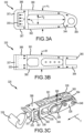
- FIGS. 3A, 3B and 3C various schematic views of a latch mechanism 320, or components thereof, similar to the latch mechanism 220 above described, are provided.
- a side view and an overhead view, respectively, of a hook body 330 similar to the hook body 230 described above, are provided, while a perspective view of various components of the latch mechanism 320, including the hook body 330, is provided in FIG. 3C .
- the hook body includes a first upper longitudinal beam 360 and a first lower longitudinal beam 362 and a second upper longitudinal beam 361 and a second lower longitudinal beam (hidden) (or a plurality of longitudinal members).
- the disclosure contemplates the various beams being parallel with a longitudinal direction Y (e.g., the Y-direction shown in FIG. 2 ) or within a deviation ranging between about zero degrees (0°) and about twenty (20°) from being parallel to the longitudinal direction (e.g., the deviation being in the Z or X directions shown in FIG. 2 ).
- the first upper longitudinal beam 360 and the first lower longitudinal beam 362 are connected to a first aft flange 364, while the second upper longitudinal beam 361 and the second lower longitudinal beam are connected to a second aft flange 365.
- the first aft flange 364 and the second aft flange 365 are coupled to a first aft link 328 and a second aft link 329, respectively, via an aft pin 348, similar to the second pin 248 (or aft pin) described above, which is also coupled to a latch handle, similar to the latch handle 222 described above.
- aft pin 348 similar to the second pin 248 (or aft pin) described above
- latch handle similar to the latch handle 222 described above.
- first upper longitudinal beam 360 and the second upper longitudinal beam 361 are connected to a forward upper plate 366, while the first lower longitudinal beam 362 and the second lower longitudinal beam are connected to a forward lower plate 367.
- the forward upper plate 366 and the forward lower plate 367 are connected to a hook body load bearing plate 357, similar to the hook body load bearing plate 257 described above.
- the latch mechanism 320 includes an adjustment nut 356 threadedly engaged with a shaft 358 that is connected to a hook 338.
- a bearing block 355 is positioned between the adjustment nut 356 and the hook body load bearing plate 357.
- the bearing block 355 receives the axial load place on the adjustment nut 356 when the latch mechanism 320 assumes a deployed or a loaded state and distributes the load throughout the hook body load bearing plate 357. As described further below, the distributed load is then transferred via the longitudinal beams to the first aft flange 364 and to the second aft flange 365 and ultimately to the aft pin 348 via an efficient load transfer design of the hook body 330.
- FIGS. 3A-3C the load paths resulting from a load placed on the latch mechanism 320 are illustrated.
- a compressive load F is translated through the bearing block 355 and into the hook body load bearing plate 357.
- the compressive load on the hook body load bearing plate 357 is then translated into tensile loads that are distributed throughout the various structural components of the hook body 330.
- the tensile load is distributed and translated through the forward upper plate 366 and the forward lower plate 367 and then through, respectively, the first upper longitudinal beam 360 and the second upper longitudinal beam 361 and the first lower longitudinal beam 362 and the second lower longitudinal beam.
- the tensile load is then distributed and translated through the first aft flange 364 and to the second aft flange 365 and ultimately to the aft pin 348.
- each of the first upper longitudinal beam 360, the second upper longitudinal beam 361, the first lower longitudinal beam 362 and the second lower longitudinal beam are oriented essentially in the axial direction, from the forward upper plate 366 and the forward lower plate 367 to the first aft flange 364 and to the second aft flange 365.
- the hook body 330 does not exhibit any elements within the structure where the load paths deviate substantially from the axial direction, which is the same direction the load paths traverse.
- the box-like structure that results in the efficient load path described above is a result of the hook body 330 having a constant or essentially constant height Hi (or hook body height) and a constant or essentially constant width W (or hook body width), both of which are essentially orthogonal to the axial load paths extending through the various structural elements above described.
- an axial cutout 344 similar to the axial cutout 244 described above with reference to FIG. 2 , also exhibits an essentially longitudinal or axial configuration. As illustrated in FIG. 3A , for example, the axial cutout 344 exhibits a constant or essentially constant height H 2 (or axial cutout height) along an axial length L of the axial cutout 344.
- FIGS. 4A, 4B and 4C various schematic views of a latch mechanism 420, or components thereof, similar to the latch mechanism 220 and the latch mechanism 320 above described, are provided.
- FIGS. 4A and 4B for example, a side view and an overhead view, respectively, of a hook body 430, similar to the hook body 230 and the hook body 330 described above, are provided, while a perspective view of various components of the latch mechanism 420, including the hook body 430, is provided in FIG. 4C .
- the hook body includes an upper longitudinal beam 460 and a lower longitudinal beam 462 (or a plurality of longitudinal members).
- the upper longitudinal beam 460 and the lower longitudinal beam 462 are connected to an aft flange 464.
- the aft flange 464 is coupled to a first aft link 428 and a second aft link 429 via an aft pin 448, similar to the second pin 248 (or aft pin) described above, which is also coupled to a latch handle, similar to the latch handle 222 described above.
- the disclosure contemplates the various beams being parallel with a longitudinal direction Y (e.g., the Y-direction shown in FIG.
- the disclosure contemplates the various longitudinal beams being substantially straight and running parallel with respect to a longitudinal direction or within a deviation ranging between about zero degrees (0°) and about twenty (20°) from running parallel to the longitudinal direction.
- the upper longitudinal beam 460 is connected to a forward upper plate 466, while the lower longitudinal beam 462 is connected to a forward lower plate 467.
- the forward upper plate 466 and the forward lower plate 467 are connected to a hook body load bearing plate 457, similar to the hook body load bearing plate 257 and to the hook body load bearing plate 357 described above.
- the forward upper plate 466 lies or is disposed within an upper plane that is substantially perpendicular to the hook body load bearing plate 457 and extends in the longitudinal direction away from the load bearing plate ( i.e., toward an aft direction).
- the forward lower plate 467 lies or is disposed within a lower plane that is substantially perpendicular to the hook body load bearing plate 457 and extends in the longitudinal direction away from the load bearing plate ( i.e., toward the aft direction).
- the latch mechanism 420 includes an adjustment nut 456 threadedly engaged with a shaft 458 that is connected to a hook 438.
- a bearing block 455 is positioned between the adjustment nut 456 and the hook body load bearing plate 457.
- the bearing block 455 receives the axial load placed on the adjustment nut 456 when the latch mechanism 420 assumes a deployed or a loaded state and distributes the load throughout the hook body load bearing plate 457.
- the distributed load is then transferred via the longitudinal beams to the aft flange 464 and ultimately to the aft pin 448 via an efficient load transfer design of the hook body 430.
- FIGS. 4A, 4B and 4C the load paths resulting from a load placed on the latch mechanism 420 are illustrated.
- a compressive load F e.g., as illustrated in FIG. 4A
- the compressive load on the hook body load bearing plate 457 is then translated into tensile loads that are distributed throughout the various structural components of the hook body 430.
- the tensile load is distributed and translated through the forward upper plate 466 and the forward lower plate 467 and then through, respectively, the upper longitudinal beam 460 and the lower longitudinal beam 462.
- the tensile load is then distributed and translated through the aft flange 464 and ultimately to the aft pin 448.
- each of the upper longitudinal beam 460 and the lower longitudinal beam 462 are oriented essentially in the axial direction, from the forward upper plate 466 and the forward lower plate 467 to the aft flange 464.
- the hook body 430 does not exhibit any elements within the structure where the load paths deviate substantially from the axial direction.
- the box-like structure that results in the efficient load path described above is a result of the hook body 430 having a constant or essentially constant height Hi (or hook body height) and a constant or essentially constant width W (or hook body width), both of which are essentially orthogonal to the axial load paths extending through the various structural elements above described.
- an axial cutout 444 similar to the axial cutout 244 and the axial cutout 344 described above, also exhibits an essentially longitudinal or axial configuration. As illustrated in FIG. 4A , for example, the axial cutout 444 exhibits a constant or essentially constant height H 2 (or axial cutout height) along an axial length L of the axial cutout 444.
- the latch mechanism 520 includes a hook body 530 having similar structural elements and characteristics as the hook body 330 or the hook body 430 described above, so those elements and characteristics are not repeated here.
- the bearing block 555 includes a block load bearing plate 501 having a first side 503 (or an aft side) and a protrusion 505 (or a plurality of protrusions) configured to engage an aperture 507 (or one of a plurality of apertures) that extends into a first side 509 (or a forward side) of the adjustment nut 556.
- the protrusion 505 and the aperture 507 are configured to define a lock mechanism (e.g ., a detent mechanism) that locks or maintains the position of the adjustment nut 556 with respect to the bearing block 555 or, in other words, selectively prevents rotation of an adjustment mechanism (e.g ., the adjustment nut 556) about the longitudinal axis.
- a lock mechanism e.g ., a detent mechanism
- the bearing block 555 further includes a first boss 515 (or an aft boss) configured to engage a recess 517 that extends axially ( e.g ., in an axial direction along a longitudinal axis A) into the first side 509 of the adjustment nut 556 and a second boss 511 (or a forward boss) configured to engage a plate aperture 513 that extends axially through a hook body load bearing plate 557 of the hook body 530.
- a first boss 515 or an aft boss
- a recess 517 that extends axially (e.g ., in an axial direction along a longitudinal axis A) into the first side 509 of the adjustment nut 556
- a second boss 511 or a forward boss
- a bearing block 575 may include an aperture 579 (or a plurality of apertures) that extends into the block load bearing plate, while an adjustment nut 576 may include a protrusion 578 (or a plurality of protrusions) configured to engage the aperture 579 (or one of the plurality of apertures).
- an outer diameter 519 of the second boss 511 (or a second boss outer diameter) is defined and configured to tightly engage an interior surface of the plate aperture 513, where the interior surface of the plate aperture 513 is defined by an inner diameter 521 (or a plate aperture inner diameter).
- the inner diameter 521 of the plate aperture 513 and the outer diameter 519 of the second boss 511 define a press-fit tolerance of within five or ten thousandths of an inch ( ⁇ 125 to 250 microns) or, in various embodiments, within one or two thousandths of an inch ( ⁇ 25 to 50 microns).
- an inner diameter 523 of the second boss 511 (or a second boss inner diameter) and an outer diameter 525 of a shaft 558 (or a shaft outer diameter) coupled to a hook 538, where the shaft 558 and the hook 538 comprise a hook mechanism 536 define a suitable sliding-fit tolerance of within twenty or forty thousandths of an inch ( ⁇ 500 to 1000 microns) or, in various embodiments, within five or ten thousandths of an inch ( ⁇ 125 to 250 microns) clearance as to prevent the hook shaft threads from bearing out in the second boss inner diameter.
- outer diameter 525 of the shaft 558 may be based on an outer diameter of a threaded shaft, the important feature being the shaft 558 is configured to slide axially or longitudinally within the second boss 511 without substantial lateral movement with respect to the longitudinal axis A and without bearing against the second boss 511.
- the hook 538 and the shaft 558 are described as separate components, the disclosure contemplates the two components can be and has been described as being a single-piece, monolithic component.
- an outer diameter 527 of the first boss 515 is defined and configured to engage an interior surface of the recess 517 of the adjustment nut 556, where the interior surface of the recess 517 is defined by an inner diameter 529.
- the inner diameter 529 of the recess 517 and the outer diameter 527 of the first boss 515 define a sliding-fit tolerance of within twenty or forty thousandths of an inch ( ⁇ 500 to 1000 microns) or, in various embodiments, within five or ten thousandths of an inch ( ⁇ 125 to 250 microns).
- An inner diameter 531 of the first boss 515 is typically equal to the inner diameter 523 of the second boss 511, which provides the same sliding-fit tolerance of within twenty or forty thousandths of an inch ( ⁇ 500 to 1000 microns) or, in various embodiments, within five or ten thousandths of an inch ( ⁇ 125 to 250 microns) between the inner diameter 531 of the first boss 515 and the outer diameter 525 of the shaft 558 coupled to the hook 538.
- the sliding-fit tolerance between the inner diameter 529 of the recess 517 and the outer diameter 527 of the first boss 515 permit the two associated components (i.e ., the bearing block 555 and the adjustment nut 556) to remain tightly and precisely aligned in an axial direction along the longitudinal axis A with minimal ability to move with respect to one another in a lateral direction with respect to the longitudinal axis A.
- the press-fit tolerance and the sliding-fit tolerance values above defined enable a center point 533 of the hook 538 and a center point of a forward pin 546 (similar to the first pin 246 (or the forward pin) described above with reference to FIG. 2 ) to be maintained on the longitudinal axis A that extends along the latch mechanism 520. Maintaining this orientation serves to redistribute the load from the adjustment nut 556, through the bearing block 555, and to the structural elements and beams that make up the hook body 530. Maintaining the orientation also serves to tightly and precisely align the hook 538 and the shaft 558 with the hook body 530 along the longitudinal axis A, thereby preventing various moments or torques that might otherwise occur when loading a similar latch mechanism without the disclosed features of the bearing block 555.
- the bearing block 555 and, in particular, the block load bearing plate 501 is configured to distribute the loads placed on it throughout the hook body load bearing plate 557, thus enabling the loads to be evenly distributed throughout the longitudinal beams, with the loads being primarily tensile loads in the axial direction without moments or torques placed on the beams.
- the load distribution facilitates smaller, lighter and more compact hook bodies to be incorporated into a latch mechanism.
- the disclosure saves cost associated with designing around tolerance stack-ups occurring between multiple apertures in a hook body, a bearing block without first and second bosses and an adjustment nut to maintain alignment of a shaft within the hook body, as all the tolerances are now essentially confined between the first boss 515 and the adjustment nut 556, the second boss 511 and the hook body load bearing plate 557 and between the first boss 515, the second boss 511 and the shaft 558, each of which may be more readily controlled without concern to tolerance stack-ups.
- the second boss 511 also enables a substantial reduction or elimination of torques or moments with respect to the hook body 530, while both the first boss 515 and the second boss 511, in conjunction with the tolerances they provide with respect to adjoining components (e.g ., the shaft 558 and the adjustment nut 556) precisely center the shaft 558 with respect to the longitudinal axis A and maintain a precise axial disposition of the shaft 558 with respect to the longitudinal axis A.
- a reduction or elimination of such torques or moments also serves to maintain minimum stress levels within the hook body 530, particularly at the portions where the hook body load bearing plate 557 adjoins other various members of the hook body 530. Additionally, the added bearing block bosses significantly reduces the stress at the hook body weakest section i.e., the hook body aperture by increasing the moment of inertia (I) through the critical section.
- a hook body comprising a plurality of elements, such as, for example, longitudinal beams, aft flanges, upper and lower plate members and load bearing plates
- the disclosure contemplates embodiments where each of the various elements is incorporated into a single-piece, monolithic component when fabricated.
- the longitudinal beams include the plate members as well as the aft flanges into single-piece, monolithic longitudinal members.
- the term longitudinal member may be construed to include each (or one or more of) of a plate, a longitudinal beam and an aft flange.
- references to "one embodiment,” “an embodiment,” “various embodiments,” etc. indicate that the embodiment described may include a particular feature, structure, or characteristic, but every embodiment may not necessarily include the particular feature, structure, or characteristic. Moreover, such phrases are not necessarily referring to the same embodiment. Further, when a particular feature, structure, or characteristic is described in connection with an embodiment, it is submitted that it is within the knowledge of one skilled in the art to affect such feature, structure, or characteristic in connection with other embodiments whether or not explicitly described. After reading the description, it will be apparent to one skilled in the relevant art(s) how to implement the disclosure in alternative embodiments.
- Numbers, percentages, or other values stated herein are intended to include that value, and also other values that are about or approximately equal to the stated value, as would be appreciated by one of ordinary skill in the art encompassed by various embodiments of the present disclosure.
- a stated value should therefore be interpreted broadly enough to encompass values that are at least close enough to the stated value to perform a desired function or achieve a desired result.
- the stated values include at least the variation to be expected in a suitable industrial process, and may include values that are within 10%, within 5%, within 1%, within 0.1%, or within 0.01% of a stated value.
- the terms “substantially,” “about” or “approximately” as used herein represent an amount close to the stated amount that still performs a desired function or achieves a desired result.
- the term “substantially,” “about” or “approximately” may refer to an amount that is within 10% of, within 5% of, within 1% of, within 0.1% of, and within 0.01% of a stated amount or value
Landscapes
- Engineering & Computer Science (AREA)
- Aviation & Aerospace Engineering (AREA)
- Mechanical Engineering (AREA)
- Structural Engineering (AREA)
- Connection Of Plates (AREA)
- Hooks, Suction Cups, And Attachment By Adhesive Means (AREA)
Applications Claiming Priority (2)
| Application Number | Priority Date | Filing Date | Title |
|---|---|---|---|
| US17/132,489 US11668124B2 (en) | 2020-12-23 | 2020-12-23 | Encapsulated bearing block design for adjustable hook latch |
| EP21211334.4A EP4019720B1 (de) | 2020-12-23 | 2021-11-30 | Gekapselte lagerblockkonstruktion für einstellbare hakenverschlüsse |
Related Parent Applications (2)
| Application Number | Title | Priority Date | Filing Date |
|---|---|---|---|
| EP21211334.4A Division-Into EP4019720B1 (de) | 2020-12-23 | 2021-11-30 | Gekapselte lagerblockkonstruktion für einstellbare hakenverschlüsse |
| EP21211334.4A Division EP4019720B1 (de) | 2020-12-23 | 2021-11-30 | Gekapselte lagerblockkonstruktion für einstellbare hakenverschlüsse |
Publications (2)
| Publication Number | Publication Date |
|---|---|
| EP4245665A2 true EP4245665A2 (de) | 2023-09-20 |
| EP4245665A3 EP4245665A3 (de) | 2024-01-24 |
Family
ID=78844556
Family Applications (2)
| Application Number | Title | Priority Date | Filing Date |
|---|---|---|---|
| EP21211334.4A Active EP4019720B1 (de) | 2020-12-23 | 2021-11-30 | Gekapselte lagerblockkonstruktion für einstellbare hakenverschlüsse |
| EP23186383.8A Pending EP4245665A3 (de) | 2020-12-23 | 2021-11-30 | Gekapselte lagerblockkonstruktion für einstellbare hakenverschlüsse |
Family Applications Before (1)
| Application Number | Title | Priority Date | Filing Date |
|---|---|---|---|
| EP21211334.4A Active EP4019720B1 (de) | 2020-12-23 | 2021-11-30 | Gekapselte lagerblockkonstruktion für einstellbare hakenverschlüsse |
Country Status (2)
| Country | Link |
|---|---|
| US (1) | US11668124B2 (de) |
| EP (2) | EP4019720B1 (de) |
Families Citing this family (8)
| Publication number | Priority date | Publication date | Assignee | Title |
|---|---|---|---|---|
| US12359479B2 (en) | 2014-03-13 | 2025-07-15 | Qrp, Inc. | Hook latch with adjustable throw |
| EP4316990B1 (de) * | 2022-08-03 | 2026-05-06 | Rohr, Inc. | Einstellbarer haken mit indexierendem lagerbock |
| US12012790B2 (en) * | 2022-09-02 | 2024-06-18 | Rohr, Inc. | Latch assembly |
| CN115306238B (zh) * | 2022-09-07 | 2025-07-22 | 西安艾力特航空科技有限公司 | 一种用于飞机发动机罩的钩子锁 |
| FR3140864A1 (fr) * | 2022-10-14 | 2024-04-19 | Lisi Aerospace | Verrou à crochet pour panneau d’aéronef |
| US12371180B2 (en) * | 2023-04-03 | 2025-07-29 | Rohr, Inc. | Long throw latch for aircraft system |
| US12420938B2 (en) | 2023-05-01 | 2025-09-23 | Rohr, Inc. | Misalignment latch for an aircraft system |
| FR3151838A1 (fr) * | 2023-07-31 | 2025-02-07 | Safran Nacelles | Verrou pour nacelle d’ensemble propulsif |
Family Cites Families (20)
| Publication number | Priority date | Publication date | Assignee | Title |
|---|---|---|---|---|
| US2904141A (en) * | 1957-04-22 | 1959-09-15 | Clark Hartwell | Adjustable hook latch |
| US4183564A (en) * | 1978-03-01 | 1980-01-15 | Hartwell Corporation | Externally accessible adjuster for flush latches |
| US4320912A (en) * | 1979-09-10 | 1982-03-23 | Rohr Industries, Inc. | Cowl door latch adjustment fitting assembly |
| US4478446A (en) * | 1979-12-17 | 1984-10-23 | Avibank Mfg., Inc. | Adjustable keeper assembly |
| US4530529A (en) * | 1980-05-27 | 1985-07-23 | Hartwell Corporation | Externally accessible adjuster for flush latches |
| US4798408A (en) * | 1986-04-23 | 1989-01-17 | Rexnord Inc. | Adjustable latching mechanism |
| US5620212A (en) * | 1995-08-28 | 1997-04-15 | Hartwell Corporation | Low profile hook latch assembly |
| US5984382A (en) | 1998-03-13 | 1999-11-16 | Hartwell Corporation | Extended reach latch |
| WO2011115792A1 (en) * | 2010-03-18 | 2011-09-22 | Alcoa Inc. | Latch with adjustable handle |
| US8870149B2 (en) * | 2010-03-29 | 2014-10-28 | Carlisle Interconnect Technologies, Inc. | Hold-down assembly |
| FR2966555B1 (fr) * | 2010-10-25 | 2013-08-16 | Lisi Aerospace Sas | Verrou a crochet muni d'un dispositif de positionnement et procede de montage d'un tel verrou |
| FR2991669B1 (fr) * | 2012-06-11 | 2014-07-11 | Lisi Aerospace | Verrou a crochet |
| US9273488B1 (en) * | 2013-07-15 | 2016-03-01 | Avibank Manufacturing, Inc. | Positive locking keeper |
| US10173782B2 (en) | 2015-03-13 | 2019-01-08 | Qrp, Inc. | Toggle link latch |
| ES2876924T3 (es) * | 2015-09-01 | 2021-11-15 | Hartwell Corp | Pestillo de gancho de enlace único |
| US10760304B2 (en) * | 2015-09-01 | 2020-09-01 | Howmet Aerospace Inc. | Adjustable hook latch |
| ES2805826T3 (es) * | 2016-03-10 | 2021-02-15 | Hartwell Corp | Cerrojo de gancho con alto desplazamiento |
| US20180128028A1 (en) * | 2016-11-08 | 2018-05-10 | Centrix Aero, LLC | Latch system with a highly visible hook latch and method for operating said hook latch |
| WO2020159920A1 (en) * | 2019-01-28 | 2020-08-06 | Hartwell Corporation | Clevis-sensing adjustable hook latch |
| US11866189B2 (en) * | 2020-03-26 | 2024-01-09 | Hartwell Corporation | Latching system with movable anti-shear mechanism |
-
2020
- 2020-12-23 US US17/132,489 patent/US11668124B2/en active Active
-
2021
- 2021-11-30 EP EP21211334.4A patent/EP4019720B1/de active Active
- 2021-11-30 EP EP23186383.8A patent/EP4245665A3/de active Pending
Also Published As
| Publication number | Publication date |
|---|---|
| US20220195765A1 (en) | 2022-06-23 |
| US11668124B2 (en) | 2023-06-06 |
| EP4019720A1 (de) | 2022-06-29 |
| EP4019720B1 (de) | 2023-08-30 |
| EP4245665A3 (de) | 2024-01-24 |
Similar Documents
| Publication | Publication Date | Title |
|---|---|---|
| US11668124B2 (en) | Encapsulated bearing block design for adjustable hook latch | |
| EP4015394B1 (de) | Verstellbarer hakenverschluss mit effizienter laststrecke | |
| EP4269251A1 (de) | Flugzeugsicherheitshalter zur verriegelungsverwendung | |
| EP3705394B1 (de) | Gehäuse einer hilfsstromeinheit und verfahren zur herstellung davon | |
| AU2019201978B2 (en) | Wing flap with torque member and method for forming thereof | |
| US11933353B2 (en) | Three piece failsafe clevis | |
| US6328256B1 (en) | Low-height tunable tilt rotor downstop | |
| US20220185449A1 (en) | Apparatus, system and method for supporting a wing flap of an aircraft | |
| AU2019201979B2 (en) | Wing flap with torque member and method for forming thereof | |
| US20190300148A1 (en) | Wing flap with torque member and method for forming thereof | |
| US10882629B2 (en) | Roll load bearing aircraft propulsor moveable panel systems and methods | |
| EP0126840A1 (de) | Struktur eines Scharniers | |
| EP4180333A1 (de) | Flugzeugsicherheitsverriegelung | |
| US12428870B2 (en) | Handle assembly for escape hatch | |
| US11787533B2 (en) | Rotor assemblies for rotorcraft | |
| US20240327010A1 (en) | Long throw latch for aircraft system | |
| US12173668B2 (en) | Articulating slider for nacelle | |
| US20260048831A1 (en) | Joint assembly | |
| US20250020156A1 (en) | Nut design for actuator system | |
| CA2314835A1 (en) | Low-height tunable tilt rotor downstop | |
| CN121626401A (zh) | 一种对开飞机舱门 |
Legal Events
| Date | Code | Title | Description |
|---|---|---|---|
| PUAI | Public reference made under article 153(3) epc to a published international application that has entered the european phase |
Free format text: ORIGINAL CODE: 0009012 |
|
| STAA | Information on the status of an ep patent application or granted ep patent |
Free format text: STATUS: THE APPLICATION HAS BEEN PUBLISHED |
|
| AC | Divisional application: reference to earlier application |
Ref document number: 4019720 Country of ref document: EP Kind code of ref document: P |
|
| AK | Designated contracting states |
Kind code of ref document: A2 Designated state(s): AL AT BE BG CH CY CZ DE DK EE ES FI FR GB GR HR HU IE IS IT LI LT LU LV MC MK MT NL NO PL PT RO RS SE SI SK SM TR |
|
| REG | Reference to a national code |
Ref country code: DE Ref legal event code: R079 Free format text: PREVIOUS MAIN CLASS: B64D0029060000 Ipc: E05B0063060000 |
|
| PUAL | Search report despatched |
Free format text: ORIGINAL CODE: 0009013 |
|
| AK | Designated contracting states |
Kind code of ref document: A3 Designated state(s): AL AT BE BG CH CY CZ DE DK EE ES FI FR GB GR HR HU IE IS IT LI LT LU LV MC MK MT NL NO PL PT RO RS SE SI SK SM TR |
|
| RIC1 | Information provided on ipc code assigned before grant |
Ipc: B64D 29/06 20060101ALI20231218BHEP Ipc: E05C 19/14 20060101ALI20231218BHEP Ipc: E05B 63/06 20060101AFI20231218BHEP |
|
| STAA | Information on the status of an ep patent application or granted ep patent |
Free format text: STATUS: REQUEST FOR EXAMINATION WAS MADE |
|
| 17P | Request for examination filed |
Effective date: 20240724 |
|
| RBV | Designated contracting states (corrected) |
Designated state(s): AL AT BE BG CH CY CZ DE DK EE ES FI FR GB GR HR HU IE IS IT LI LT LU LV MC MK MT NL NO PL PT RO RS SE SI SK SM TR |
|
| REG | Reference to a national code |
Ref country code: DE Ref legal event code: R079 Free format text: PREVIOUS MAIN CLASS: E05B0063060000 Ipc: B64D0029060000 |
|
| RIC1 | Information provided on ipc code assigned before grant |
Ipc: B64D 29/06 20060101AFI20260223BHEP Ipc: E05C 19/14 20060101ALI20260223BHEP Ipc: E05B 63/06 20060101ALI20260223BHEP |
|
| GRAP | Despatch of communication of intention to grant a patent |
Free format text: ORIGINAL CODE: EPIDOSNIGR1 |
|
| STAA | Information on the status of an ep patent application or granted ep patent |
Free format text: STATUS: GRANT OF PATENT IS INTENDED |
|
| INTG | Intention to grant announced |
Effective date: 20260414 |