US6328256B1 - Low-height tunable tilt rotor downstop - Google Patents
Low-height tunable tilt rotor downstop Download PDFInfo
- Publication number
- US6328256B1 US6328256B1 US09/408,337 US40833799A US6328256B1 US 6328256 B1 US6328256 B1 US 6328256B1 US 40833799 A US40833799 A US 40833799A US 6328256 B1 US6328256 B1 US 6328256B1
- Authority
- US
- United States
- Prior art keywords
- assembly
- tilt rotor
- downstop
- striker
- low
- Prior art date
- Legal status (The legal status is an assumption and is not a legal conclusion. Google has not performed a legal analysis and makes no representation as to the accuracy of the status listed.)
- Expired - Lifetime
Links
Images


Classifications
-
- B—PERFORMING OPERATIONS; TRANSPORTING
- B64—AIRCRAFT; AVIATION; COSMONAUTICS
- B64C—AEROPLANES; HELICOPTERS
- B64C27/00—Rotorcraft; Rotors peculiar thereto
- B64C27/32—Rotors
- B64C27/322—Blade travel limiting devices, e.g. droop stops
-
- B—PERFORMING OPERATIONS; TRANSPORTING
- B64—AIRCRAFT; AVIATION; COSMONAUTICS
- B64C—AEROPLANES; HELICOPTERS
- B64C29/00—Aircraft capable of landing or taking-off vertically, e.g. vertical take-off and landing [VTOL] aircraft
- B64C29/0008—Aircraft capable of landing or taking-off vertically, e.g. vertical take-off and landing [VTOL] aircraft having its flight directional axis horizontal when grounded
- B64C29/0016—Aircraft capable of landing or taking-off vertically, e.g. vertical take-off and landing [VTOL] aircraft having its flight directional axis horizontal when grounded the lift during taking-off being created by free or ducted propellers or by blowers
- B64C29/0033—Aircraft capable of landing or taking-off vertically, e.g. vertical take-off and landing [VTOL] aircraft having its flight directional axis horizontal when grounded the lift during taking-off being created by free or ducted propellers or by blowers the propellers being tiltable relative to the fuselage
-
- Y—GENERAL TAGGING OF NEW TECHNOLOGICAL DEVELOPMENTS; GENERAL TAGGING OF CROSS-SECTIONAL TECHNOLOGIES SPANNING OVER SEVERAL SECTIONS OF THE IPC; TECHNICAL SUBJECTS COVERED BY FORMER USPC CROSS-REFERENCE ART COLLECTIONS [XRACs] AND DIGESTS
- Y10—TECHNICAL SUBJECTS COVERED BY FORMER USPC
- Y10T—TECHNICAL SUBJECTS COVERED BY FORMER US CLASSIFICATION
- Y10T403/00—Joints and connections
- Y10T403/32—Articulated members
- Y10T403/32606—Pivoted
- Y10T403/32861—T-pivot, e.g., wrist pin, etc.
- Y10T403/32868—Floating pin
Definitions
- the present invention relates generally to conversion assemblies for use on tilt rotor aircraft for converting from a helicopter mode to an airplane mode, and vice versa.
- the present invention relates to a method and apparatus for stabilizing the articulating rotor portion relative to the stationary structure of the aircraft while in the airplane mode.
- Tilt rotor aircraft are hybrids between traditional helicopters and traditional propeller driven aircraft.
- Typical tilt rotor aircraft have rotor systems that are capable of articulating relative to the aircraft fuselage. This articulating portion is referred to as a nacelle.
- Tilt rotor aircraft are capable of converting from a helicopter mode, in which the aircraft can take-off, hover, and land like a helicopter; to an airplane mode, in which the aircraft can fly forward like a fixed-wing airplane.
- tilt rotor aircraft poses unique problems not associated with either helicopters or propeller driven aircraft.
- certain static and dynamic loads are generated by the tilt rotor assemblies that are not present in either conventional helicopters or fixed wing aircraft.
- aircraft stability is maintained by a support assembly referred to as a “downstop” assembly.
- the downstop assembly has two main purposes. First, the downstop assembly must provide vertical stiffness in order to react against the downward forces required to keep the nacelle from rising throughout the flight envelope. Second, the downstop assembly must provide enough lateral stiffness to ensure flight stability. The exact amount of lateral stiffness is based upon aircraft geometry, flight envelope requirements, adjacent part stiffness, and several other factors that are unknown until flight testing is underway.
- the downstop assembly be tunable in such a way that redesign of adjacent parts is not required as a result of the need to increase or decrease the lateral stiffness. If the lateral stiffness is matched or tuned to a particular aircraft's minimum lateral stiffness requirement, then the aircraft's wing structure can be isolated from damaging lateral static and oscillatory loads.
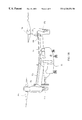
- FIG. 1A is a perspective view of a tilt rotor aircraft in an airplane mode.
- FIG. 1B is a perspective view of a tilt rotor aircraft in a helicopter mode.
- FIG. 2A is an exploded perspective view of a striker assembly of a low-height tunable tilt rotor downstop according to the present invention.
- FIG. 2B is an assembled perspective view of the striker assembly of FIG. 2 A.
- FIG. 2C is a cut-away view of Joint A of the striker assembly of FIG. 2 A.
- FIG. 3 is a front view of the striker arm of the striker assembly of FIGS. 2A and 2B.
- FIG. 4 is an exploded perspective view illustrating the attachment of the striker assembly of FIGS. 2A and 2B to a prop-rotor gear box assembly.
- FIG. 5 is an exploded perspective view of a cradle assembly of the low-height tunable tilt rotor downstop according to the present invention.
- FIG. 6 is a perspective view illustrating the attachment of the cradle assembly of FIG. 5 to an outboard wing rib and a forward wing spar.
- FIG. 7 is a perspective view of the assembled low-height tunable tilt rotor downstop according to the present invention, including the striker assembly of FIGS. 2A and 2B and the cradle assembly of FIGS. 5 and 6.
- Tilt rotor aircraft 11 has an airframe 13 and wings 15 a and 15 b coupled to airframe 13 .
- wings 15 a and 15 b terminate with tilt rotor assemblies 17 a and 17 b, respectively.
- Fairings 18 a and 18 b for reducing drag are disposed between tilt rotor assemblies 17 a and 17 b and wings 15 a and 15 b.
- Tilt rotor assemblies 17 a and 17 b each may include an engine, a transmission, and a gear box (see FIG. 5) for driving prop-rotors 19 a and 19 b.
- Conversion actuators see FIG.
- tilt rotor aircraft 11 can be flown and operated like a conventional fixed-wing propeller driven aircraft.
- tilt rotor aircraft 11 can take-off, hover, land, and be operated like a conventional rotary wing aircraft or helicopter.
- a striker assembly 31 includes a base member 33 configured to receive an angled, tunable striker arm 35 .
- Base member 33 is preferably made of aluminum, but may be made of any other sufficiently rigid material.
- Base member 33 includes a plurality of mounting apertures 36 .
- Striker arm 35 is generally L-shaped having a post portion 37 and an leg portion 39 .
- Striker arm 35 is preferably made of titanium, but may be made of other materials for which the mechanical properties, in particular bending stiffness, may be adjusted, or “tuned,” by altering the geometrical dimensions of striker arm 35 . This tuning feature of striker arm 35 plays a central role in the present invention, and will be discussed in more detail below.
- Post portion 37 and leg portion 39 of striker arm 35 intersect at a generally cylindrical corner portion 41 .
- Corner portion 41 includes a cylindrical bore 43 that passes transversely through corner portion 41 along an axis 45 .
- Bushings 47 are coupled to the interior of bore 43 on each end of bore 43 .
- Bushings 47 are preferably anti-friction bushings, such as bushings having a teflon lining.
- Bushings 47 have an interference fit with bore 43 , but may be coupled to bore 43 by other well known means.
- Leg portion 39 has a transverse width w that is generally constant over the length of leg portion 39 .
- Post portion 37 preferably tapers inwardly from corner portion 41 to a tip portion 49 .
- Tip portion 49 is generally cylindrical along an axis 51 .
- Leg portion 39 extends away from corner portion 41 and terminates at a forked end 53 having an upper flat 53 a and a generally parallel lower flat 53 b. Striker arm 35 will be explained in more detail below
- Base member 33 includes a plurality of lugs 55 a and 55 b .
- Lugs 55 a and 55 b are generally parallel.
- Lugs 55 a and 55 b include bores 57 a and 57 b, respectively, passing therethrough.
- Bushings 61 a and 61 b are coupled to the interior of bores 57 a and 57 b, respectively, along an axis 59 .
- Bushings 61 a and 61 b are similar in construction to bushings 47 .
- Bushings 61 a and 61 b are preferably anti-friction bushings, such as bushings having a teflon lining.
- Bushings 61 a and 61 b are preferably interference fit into bores 57 a and 57 b, but may be coupled to lugs 55 a and 55 b by other well known means.
- a slip bushing 63 is received by bushing 61 a.
- Slip bushing 63 is held in place between a bushing flange 61 c of bushing 61 b and a washer 65 a.
- a bolt 67 passes along axis 59 through washer 65 b, bushing 61 b, bushing 63 , and washer 65 a; and is releasably received by a nut 69 having a pin 71 . In this manner, an anti-friction pivot joint A (see FIG. 2C) is created, about which post portion 37 and leg portion 39 pivot.
- base member 33 includes a second plurality of lugs 73 a and 73 b.
- Lugs 73 a and 73 b are generally parallel to each other and parallel to axis 59 .
- Lugs 73 a and 73 b include bores 75 a and 75 b, respectively, passing therethrough.
- Bushings 79 a and 79 b are coupled to the interior of bores 75 a and 75 b, respectively, along an axis 77 .
- Bushings 79 a and 79 b are similar in construction to bushings 47 .
- Bushings 79 a and 79 b are preferably anti-friction bushings, such as bushings having a teflon lining.
- Bushings 79 a and 79 b are preferably interference fit into bores 75 a and 75 b, but may be coupled to lugs 73 a and 73 b by other well known means.
- a retainer pin 81 is received through bushings 79 a and 79 b .
- Retainer pin 81 has a pair of recessed flats 83 a and 83 b.
- Flats 83 a and 83 b are generally parallel to each other and parallel to axis 59 . It is preferred that at least recessed portions 83 a and 83 b of retainer pin 81 are coated with an anti-friction material, such as KARON, which is commercially available from the Kamatics Corporation of Bloomfield, Conn.
- Retainer pin 81 is free to rotate within tabs 73 a and 73 b about axis 77 .
- Flat recessed portions 83 a and 83 b are configured to slidingly receive fork 53 , thereby forming a sliding and pivoting joint B (see FIG. 2 B). Because fork 53 is allowed to slide relative to retainer pin 81 , and rotate relative to axis 77 , leg portion 39 will flex by bending as a lateral load is applied to post portion 37 . However, leg portion 39 has sufficient stiffness to prevent flats 53 a and 53 b from translating enough relative to tabs 73 a and 73 b such that fork 53 releases from retainer pin 81 . In other words, the sliding connection of fork 53 with retainer pin 81 allows post portion 37 to pivot about axis 59 , i.e., joint A.
- slot 90 allows leg portion 39 of striker arm 35 to remain in a generally horizontal position and flex or bend in a vertical plane without restriction. Slot 90 is configured to accommodate variations in the vertical thickness of leg portion 39 , as will be explained in more detail below. In addition, slot 90 allows striker assembly 31 to maintain an overall low vertical height or profile.
- striker arm 35 is illustrated in a front view.
- post member 37 and leg member 39 form an angle ⁇ about axis 45 .
- Angle ⁇ is not restricted; however, angles greater than 115° may adversely effect the low-height feature of the present invention.
- Post portion 37 has a vertical height h, as measured from the lowest point of tip portion 49 to axis 45 ; and leg portion 39 has a length l, as measured from the end of fork 53 to axis 45 . Due to the low-height feature of the present invention, height h is smaller than length l.
- axis 45 about which corner portion 41 is concentric, and axis 51 , about which tip portion 49 is concentric, do not have to be parallel. In general it is preferred that axis 51 be made parallel to the mast centerline of tilt rotor assemblies 17 a and 17 b . It should be understood that for certain tilt rotor aircraft, axis 45 and axis 51 may be parallel without significantly affecting the functionality of striker arm 35 .
- Leg portion 39 has a selected vertical height, or thickness t, as measured from a lower surface 91 to an upper surface 93 . Based upon thickness t, the leg portion 39 has a selected vertical cross-section, or thickness profile. It is preferred that striker arm 35 be made of a rigid material, for which the bending stiffness of leg portion 39 may be selectively varied according to thickness t, and the corresponding thickness profile. It is preferred that width w and length l of leg portion 39 remain constant so as not to require changes to retainer pin 81 or slot 90 (see FIG. 2 B).
- leg portion 39 of striker arm 35 is made of titanium, has length l of about 7.0 inches, height h of about 2.5 inches, and thickness t varying from about 0.66 inches near corner portion 41 to about 0.38 inches near fork 53 , then leg portion 39 of has a bending stiffness range of about 50,000 pounds per inch to about 150,000 pounds per inch.
- the bending stiffness of leg portion 39 may be selectively determined by altering thickness t of leg portion 39 .
- striker arm 35 may be tuned to a selective bending stiffness by altering the thickness profile of leg portion 39 .
- the bending stiffness of leg portion 39 will increase as thickness t increases.
- the bending stiffness of leg portion 39 is greater for a thickness profile having a variable thickness t 1 , than for a thickness profile having a variable thickness t; and the bending stiffness of leg portion 39 is less for a thickness profile having a variable thickness t 2 , than for a thickness profile having a variable thickness t.
- tip portion 49 of post portion 37 be coated with a very hard material, such as tungsten carbide, to resist fretting against the surface of a V-block 115 (see FIG. 5 ).
- a very hard material such as tungsten carbide
- FIG. 4 assembled striker assembly 31 of FIG. 2B is shown being coupled to a prop-rotor gear box assembly 101 .
- a prop-rotor gear box assembly 101 is disposed within each tilt rotor assembly 17 a and 17 b (see FIGS. 1 A and 1 B).
- Prop-rotor gear box assemblies 101 drive rotor hubs 19 a and 19 b.
- Each prop-rotor gear box assembly 101 is adapted to be coupled to striker assembly 31 , preferably by the inclusion of studs 103 disposed on a coupling portion 104 . Studs 103 are aligned with and releasably received by mounting means 36 of base member 33 .
- a shear boss 105 is coupled to base member 33 to provide additional support against shear forces acting between striker assembly 31 and prop-rotor gear assembly 101 .
- a scrim 107 preferably an epoxy scrim, is bonded to base member 33 to provide fretting protection.
- a solid shim 109 preferably made of a metallic material, is disposed between scrim 107 of base member 33 and coupling portion 104 of prop-rotor gear assembly 101 to provide adjustment capability.
- Cradle assembly 111 includes an attachment portion 113 and yaw restraint portion, or V-block 115 .
- Attachment portion 113 is preferably made of a rigid metallic material, such as aluminum.
- V-block 115 is carried in a trough portion 117 of attachment portion 113 .
- V-block 115 is adjustably coupled to attachment portion 113 by fasteners, preferably bolts 119 .
- Trough portion 117 is preferably lined with shims 121 a and 121 b.
- Shims 121 a and 121 b are preferably aluminum peel shims which allow vertical and lateral adjustment, respectively, of V-block 115 .
- a spacer plate 123 is disposed on a forward internal face 125 of trough portion 117 . Spacer plate 123 is necessary on forward internal face 125 because tilt rotor assemblies 17 a and 17 b exert rotor thrust forces upon V-block 115 in the forward direction. Spacer plate 123 preferably includes an epoxy coating to prevent fretting. Spacer plate 123 is coupled to trough portion 117 by conventional fastening means 127 , such as bolts or rivets.
- V-block 115 is made of a rigid metallic material, such as titanium.
- V-block 115 has a rounded V-shaped groove interface portion 129 configured to releasably receive tip portion 49 of post portion 37 as tip portion 49 rotates downward with each tilt rotor assembly 17 a and 17 b during conversion into airplane mode.
- Striker interface portion 129 includes inclined surfaces 130 a and 130 b that converge to form a generally longitudinal trough 130 c. Trough 130 c is generally transverse to the lateral loads, or yaw loads, shown in FIG. 2 B. Because striker interface portion 129 is subjected to oscillatory loads from tip portion 49 , it is desirable that striker interface portion 129 have a very hard surface to resist fretting.
- V-block 115 be made of a hard metallic material, and that at least striker interface portion 129 be coated with a very hard material, such as tungsten carbide. To ensure that V-block 115 does not fret relative to attachment portion, it is preferred that V-block 115 be coated with an adhesive material, such as epoxy, on all surfaces that are in contact with shims 121 a and 121 b. Attachment portion 113 includes mounting apertures 131 .
- cradle assembly 111 is illustrated coupled to wing 15 a.
- Attachment portion 113 of cradle assembly 111 is adapted to be coupled to at least one wing spar and at least one wing rib.
- Cradle assembly 111 does not intrude into the interior of wing 15 a.
- attachment portion 113 is coupled to a forward wing spar 135 and an outboard wing rib 137 by conventional fastening means 133 , such as bolts or rivets, through mounting apertures 131 .
- trough portion 117 may extend outboard in a cantilevered fashion beyond outboard wing rib 137 to ensure that the low-height feature of the present invention is maintained.
- Attachment portion 113 is configured to allow attachment of cradle assembly 111 to wing 15 a, while not interfering with other components of wing 15 a, such as aperture 139 through which a conversion actuator spindle 143 (see FIG. 7) passes.
- cradle assembly 111 has been shown and described as being coupled to forward wing spar 135 , it should be understood that cradle assembly 111 may be coupled to other components of wing 15 a or 15 b.
- FIG. 7 the components of FIGS. 2A-6 are illustrated in an assembled fashion.
- Conventional hydraulic conversion actuators 141 are used to convert tilt rotor assemblies 17 a and 17 b between the airplane mode and the helicopter mode.
- Conversion actuators 141 pivot about spindles 143 as conversion actuators 141 actuate tilt rotor assemblies 17 a and 17 b by exerting forces on pylons 145 .
- Tilt rotor assemblies 17 a and 17 b pivot about spindles 147 that pass through rear portions 149 of wings 15 a and 15 b.
- cradle assembly 111 may be coupled to coupling portion 104 of prop-rotor gear assembly 101 , and striker assembly 31 may be coupled to wings 15 a and 15 b without affecting the functionality, tunability, or low-height feature of the present invention.
- tilt rotor assemblies 17 a and 17 b are rotated downward from the helicopter mode (see FIG. 1B) to the airplane mode (see FIG. 1 A). It is preferred that tip portion 49 be forced against V-block 115 at a selected preload while tilt rotor aircraft 11 is in the airplane mode (see FIG. 1 A). Because striker assembly 31 is coupled to prop-rotor gear assembly 101 via coupling portion 104 , as tilt rotor assemblies 17 a and 17 b reach the airplane mode, tip portions 49 of post portion 37 of striker arm 35 are forced into contact with V-blocks 115 . In this manner, the selected preload is transferred from cradle assembly 111 to wing 15 a.
- tilt rotor aircraft 11 will remain stable in the aircraft mode. If the selected preload is not maintained, tilt rotor aircraft will become unstable due to the oscillatory loads.
- the present invention provides a means of reacting the vertical preload between wings 15 a , 15 b and tilt rotor assemblies 17 a , 17 b ; and a means of isolating and absorbing both static and dynamic lateral flight loads between wings 15 a , 15 b and tilt rotor assemblies 17 a , 17 b . It is desirable that tilt rotor assemblies 17 a and 17 b receive a selected downward preload from conversion actuator 141 (see FIG. 7) such that tip portions 49 remain in contact with V-block 115 throughout the flight envelope of the aircraft.
- V-block 115 does not latch onto or lock onto tip portion 49 . It should be understood that latching or locking mechanisms may be desirable in certain situations or installations.
- cradle assembly 111 wraps around forward wing spar 135 and outboard wing rib 137 . This allows cradle assembly 111 to maintain a low-height.
Abstract
Description
Claims (32)
Priority Applications (8)
| Application Number | Priority Date | Filing Date | Title |
|---|---|---|---|
| US09/408,337 US6328256B1 (en) | 1999-09-29 | 1999-09-29 | Low-height tunable tilt rotor downstop |
| KR1020000044511A KR20010049953A (en) | 1999-08-12 | 2000-08-01 | Low-height tunable tilt rotor downstop |
| DE10037539A DE10037539B4 (en) | 1999-08-12 | 2000-08-02 | Adjustable swivel rotor down stop with low height |
| CA002314835A CA2314835A1 (en) | 1999-08-12 | 2000-08-02 | Low-height tunable tilt rotor downstop |
| GB0018823A GB2353018B (en) | 1999-08-12 | 2000-08-03 | Low height tunable tilt rotor downstop |
| IT2000MI001822A IT1318726B1 (en) | 1999-08-12 | 2000-08-04 | LOWER STOP GROUP OF AN ADJUSTABLE TILTING ROTOR SMALL HEIGHT |
| JP2000238214A JP2001080587A (en) | 1999-08-12 | 2000-08-07 | Tilt rotor down stop assembly |
| FR0010477A FR2797430B1 (en) | 1999-08-12 | 2000-08-09 | A TILT ROTOR AIRCRAFT HAVING A STOP ARRANGEMENT TOWARDS THE TILT ROTOR |
Applications Claiming Priority (1)
| Application Number | Priority Date | Filing Date | Title |
|---|---|---|---|
| US09/408,337 US6328256B1 (en) | 1999-09-29 | 1999-09-29 | Low-height tunable tilt rotor downstop |
Publications (1)
| Publication Number | Publication Date |
|---|---|
| US6328256B1 true US6328256B1 (en) | 2001-12-11 |
Family
ID=23615853
Family Applications (1)
| Application Number | Title | Priority Date | Filing Date |
|---|---|---|---|
| US09/408,337 Expired - Lifetime US6328256B1 (en) | 1999-08-12 | 1999-09-29 | Low-height tunable tilt rotor downstop |
Country Status (1)
| Country | Link |
|---|---|
| US (1) | US6328256B1 (en) |
Cited By (16)
| Publication number | Priority date | Publication date | Assignee | Title |
|---|---|---|---|---|
| US6607161B1 (en) * | 1999-09-14 | 2003-08-19 | Eurocopter | Convertible aircraft with tilting rotors |
| US20070241228A1 (en) * | 2004-09-30 | 2007-10-18 | Haynes Davie F | Compact Tiltrotor Pylon-Conversion Actuation System |
| US20090256026A1 (en) * | 2008-04-11 | 2009-10-15 | Karem Aircraft, Inc. | Tilt Actuation for a Rotorcraft |
| US20100193644A1 (en) * | 2008-04-25 | 2010-08-05 | Abe Karem | Aircraft with Integrated Lift and Propulsion System |
| US20110024552A1 (en) * | 2008-04-25 | 2011-02-03 | Karem Aircraft, Inc. | Anhedral Tip Blades for Tiltrotor Aircraft |
| US20110177748A1 (en) * | 2010-01-21 | 2011-07-21 | Zhihong Luo | Vtol model aircraft |
| CN102310942A (en) * | 2010-05-27 | 2012-01-11 | 奥格斯塔股份公司 | The non-rotation Hooke's coupling that is used for the autogyro driver element |
| US8864062B2 (en) | 2005-08-15 | 2014-10-21 | Abe Karem | Aircraft with integrated lift and propulsion system |
| USD731395S1 (en) * | 2013-10-24 | 2015-06-09 | Bell Helicopter Textron Inc. | Tiltrotor aircraft tail section |
| USD731394S1 (en) * | 2013-10-24 | 2015-06-09 | Bell Helicopter Textron Inc. | Tiltrotor aircraft with fixed engines |
| USD739335S1 (en) * | 2013-10-24 | 2015-09-22 | Bell Helicopter Textron Inc. | Tiltrotor aircraft with forward-swept wings |
| US9377784B2 (en) | 2014-07-25 | 2016-06-28 | The Boeing Company | Adaptable automatic nacelle conversion for tilt rotor aircraft |
| US10318904B2 (en) | 2016-05-06 | 2019-06-11 | General Electric Company | Computing system to control the use of physical state attainment of assets to meet temporal performance criteria |
| US10518595B2 (en) | 2013-03-15 | 2019-12-31 | Terrafugia, Inc. | Combined flying/driving vehicle with vertical takeoff and fixed-wing cruise capabilities |
| US20210122463A1 (en) * | 2019-10-29 | 2021-04-29 | Bell Textron Inc. | Conversion actuation systems and methods for tiltrotor aircraft |
| US11067164B2 (en) | 2016-04-15 | 2021-07-20 | Terrafugia, Inc. | Electronic gear shifter assembly for a dual-mode flying and driving vehicle |
Citations (5)
| Publication number | Priority date | Publication date | Assignee | Title |
|---|---|---|---|---|
| US5054716A (en) * | 1989-10-16 | 1991-10-08 | Bell Helicopter Textron Inc. | Drive system for tiltrotor aircraft |
| US5352090A (en) * | 1992-08-07 | 1994-10-04 | The United States Of America As Represented By The Administrator Of The National Aeronautics And Space Administration | System for determining aerodynamic imbalance |
| US5642982A (en) | 1995-12-11 | 1997-07-01 | Sikorsky Aircraft Corporation | Retraction/extension mechanism for variable diameter rotors |
| US5823470A (en) * | 1996-07-16 | 1998-10-20 | Mcdonnell Douglas Helicopter Co. | Split torque proprotor transmission |
| US6161800A (en) * | 1999-05-04 | 2000-12-19 | The Boeing Company | Pivoting spanwise-flow redirector for tiltrotor aircraft |
-
1999
- 1999-09-29 US US09/408,337 patent/US6328256B1/en not_active Expired - Lifetime
Patent Citations (5)
| Publication number | Priority date | Publication date | Assignee | Title |
|---|---|---|---|---|
| US5054716A (en) * | 1989-10-16 | 1991-10-08 | Bell Helicopter Textron Inc. | Drive system for tiltrotor aircraft |
| US5352090A (en) * | 1992-08-07 | 1994-10-04 | The United States Of America As Represented By The Administrator Of The National Aeronautics And Space Administration | System for determining aerodynamic imbalance |
| US5642982A (en) | 1995-12-11 | 1997-07-01 | Sikorsky Aircraft Corporation | Retraction/extension mechanism for variable diameter rotors |
| US5823470A (en) * | 1996-07-16 | 1998-10-20 | Mcdonnell Douglas Helicopter Co. | Split torque proprotor transmission |
| US6161800A (en) * | 1999-05-04 | 2000-12-19 | The Boeing Company | Pivoting spanwise-flow redirector for tiltrotor aircraft |
Cited By (28)
| Publication number | Priority date | Publication date | Assignee | Title |
|---|---|---|---|---|
| US6607161B1 (en) * | 1999-09-14 | 2003-08-19 | Eurocopter | Convertible aircraft with tilting rotors |
| US7913947B2 (en) * | 2004-09-30 | 2011-03-29 | Textron Innovations Inc. | Compact tiltrotor pylon-conversion actuation system |
| US20070241228A1 (en) * | 2004-09-30 | 2007-10-18 | Haynes Davie F | Compact Tiltrotor Pylon-Conversion Actuation System |
| US8864062B2 (en) | 2005-08-15 | 2014-10-21 | Abe Karem | Aircraft with integrated lift and propulsion system |
| US8517302B2 (en) | 2005-08-15 | 2013-08-27 | Abe Karem | Aircraft with integrated lift and propulsion system |
| US8939393B2 (en) | 2005-08-15 | 2015-01-27 | Abe Karem | Aircraft with integrated lift and propulsion system |
| US20110036955A1 (en) * | 2005-08-15 | 2011-02-17 | Abe Karem | Aircraft with Integrated Lift and Propulsion System |
| US7871033B2 (en) * | 2008-04-11 | 2011-01-18 | Karem Aircraft, Inc | Tilt actuation for a rotorcraft |
| US20090256026A1 (en) * | 2008-04-11 | 2009-10-15 | Karem Aircraft, Inc. | Tilt Actuation for a Rotorcraft |
| US8066219B2 (en) | 2008-04-25 | 2011-11-29 | Karem Aircraft, Inc. | Anhedral tip blades for tiltrotor aircraft |
| US20100193644A1 (en) * | 2008-04-25 | 2010-08-05 | Abe Karem | Aircraft with Integrated Lift and Propulsion System |
| US20110024552A1 (en) * | 2008-04-25 | 2011-02-03 | Karem Aircraft, Inc. | Anhedral Tip Blades for Tiltrotor Aircraft |
| US7861967B2 (en) * | 2008-04-25 | 2011-01-04 | Abe Karem | Aircraft with integrated lift and propulsion system |
| US20110177748A1 (en) * | 2010-01-21 | 2011-07-21 | Zhihong Luo | Vtol model aircraft |
| CN102310942B (en) * | 2010-05-27 | 2015-11-25 | 奥格斯塔股份公司 | For the non-rotating Hooke's coupling of autogyro driver element |
| CN102310942A (en) * | 2010-05-27 | 2012-01-11 | 奥格斯塔股份公司 | The non-rotation Hooke's coupling that is used for the autogyro driver element |
| US8591136B2 (en) * | 2010-05-27 | 2013-11-26 | Agusta S.P.A. | Non-rotating universal joint for a helicopter drive unit |
| US11014418B2 (en) | 2013-03-15 | 2021-05-25 | Terrafugia, Inc. | Combined flying/driving vehicle with vertical takeoff and fixed-wing cruise capabilities |
| US10518595B2 (en) | 2013-03-15 | 2019-12-31 | Terrafugia, Inc. | Combined flying/driving vehicle with vertical takeoff and fixed-wing cruise capabilities |
| USD731395S1 (en) * | 2013-10-24 | 2015-06-09 | Bell Helicopter Textron Inc. | Tiltrotor aircraft tail section |
| USD739335S1 (en) * | 2013-10-24 | 2015-09-22 | Bell Helicopter Textron Inc. | Tiltrotor aircraft with forward-swept wings |
| USD731394S1 (en) * | 2013-10-24 | 2015-06-09 | Bell Helicopter Textron Inc. | Tiltrotor aircraft with fixed engines |
| US9377784B2 (en) | 2014-07-25 | 2016-06-28 | The Boeing Company | Adaptable automatic nacelle conversion for tilt rotor aircraft |
| US11067164B2 (en) | 2016-04-15 | 2021-07-20 | Terrafugia, Inc. | Electronic gear shifter assembly for a dual-mode flying and driving vehicle |
| US10318904B2 (en) | 2016-05-06 | 2019-06-11 | General Electric Company | Computing system to control the use of physical state attainment of assets to meet temporal performance criteria |
| US10318903B2 (en) | 2016-05-06 | 2019-06-11 | General Electric Company | Constrained cash computing system to optimally schedule aircraft repair capacity with closed loop dynamic physical state and asset utilization attainment control |
| US20210122463A1 (en) * | 2019-10-29 | 2021-04-29 | Bell Textron Inc. | Conversion actuation systems and methods for tiltrotor aircraft |
| US11505313B2 (en) * | 2019-10-29 | 2022-11-22 | Textron Innovations Inc. | Conversion actuation systems and methods for tiltrotor aircraft |
Similar Documents
| Publication | Publication Date | Title |
|---|---|---|
| US6328256B1 (en) | Low-height tunable tilt rotor downstop | |
| US6220545B1 (en) | Method and apparatus for sensing preload in a tilt rotor downstop | |
| US10472057B2 (en) | Rotor assembly with high lock-number blades | |
| US5035379A (en) | Movable aircraft engine cowling | |
| US7950605B2 (en) | Torsionally de-coupled engine mount system | |
| US11618557B2 (en) | Centrifugal force bearing with piezo clutch | |
| CA2314835A1 (en) | Low-height tunable tilt rotor downstop | |
| US11299265B2 (en) | Rotor blade folding system | |
| US4681511A (en) | Low vibration helicopter rotor | |
| US20220299063A1 (en) | Three piece failsafe clevis | |
| US11027834B2 (en) | Inboard centrifugal force bearing attachment | |
| US3944170A (en) | Apparatus for producing pivotal movement | |
| EP3345829B1 (en) | Rotor assembly with high lock-number blades | |
| US10960970B2 (en) | Inboard beam with pin system for anti-rotation and centrifugal force retention | |
| EP3392134B1 (en) | Horizontal stabilizer mount for a rotorcraft | |
| EP3216695B1 (en) | Rotor assembly with high lock-number blades | |
| US11603183B2 (en) | Compliant tail structure for rotorcraft | |
| EP4001102B1 (en) | Rotor assemblies for rotorcraft | |
| CA2995295C (en) | Rotor assembly with high lock-number blades | |
| GB2059897A (en) | Helicopter rotor blade-to-hub connections | |
| Jeffery et al. | Compensating linkage for main rotor control | |
| Davidson et al. | Fan-in-Fin Antitorque Concept Study |
Legal Events
| Date | Code | Title | Description |
|---|---|---|---|
| AS | Assignment |
Owner name: BELL HELICOPTER TEXTRON INC., TEXAS Free format text: ASSIGNMENT OF ASSIGNORS INTEREST;ASSIGNORS:RYAN, MICHAEL J.;ZIMMERMAN, BRETT R.;REEL/FRAME:010495/0803;SIGNING DATES FROM 19991202 TO 19991203 |
|
| STCF | Information on status: patent grant |
Free format text: PATENTED CASE |
|
| FEPP | Fee payment procedure |
Free format text: PAYOR NUMBER ASSIGNED (ORIGINAL EVENT CODE: ASPN); ENTITY STATUS OF PATENT OWNER: LARGE ENTITY |
|
| AS | Assignment |
Owner name: TEXTRON IPMP L.P., MICHIGAN Free format text: ASSIGNMENT OF ASSIGNORS INTEREST;ASSIGNOR:BELL HELLCOPTER MICHIGAN, INC.;REEL/FRAME:016283/0404 Effective date: 20010401 Owner name: BELL HELICOPTER MICHIGAN, INC., MICHIGAN Free format text: ASSIGNMENT OF ASSIGNORS INTEREST;ASSIGNOR:BELL HELICOPTER TEXTRON, INC.;REEL/FRAME:016283/0439 Effective date: 20010401 |
|
| FPAY | Fee payment |
Year of fee payment: 4 |
|
| FPAY | Fee payment |
Year of fee payment: 8 |
|
| FPAY | Fee payment |
Year of fee payment: 12 |