US10760304B2 - Adjustable hook latch - Google Patents
Adjustable hook latch Download PDFInfo
- Publication number
- US10760304B2 US10760304B2 US15/251,535 US201615251535A US10760304B2 US 10760304 B2 US10760304 B2 US 10760304B2 US 201615251535 A US201615251535 A US 201615251535A US 10760304 B2 US10760304 B2 US 10760304B2
- Authority
- US
- United States
- Prior art keywords
- star wheel
- housing
- hook
- holes
- flange
- Prior art date
- Legal status (The legal status is an assumption and is not a legal conclusion. Google has not performed a legal analysis and makes no representation as to the accuracy of the status listed.)
- Active, expires
Links
- 230000006835 compression Effects 0.000 claims abstract description 16
- 238000007906 compression Methods 0.000 claims abstract description 16
- 238000012986 modification Methods 0.000 description 2
- 230000004048 modification Effects 0.000 description 2
- 230000000994 depressogenic effect Effects 0.000 description 1
Images


Classifications
-
- E—FIXED CONSTRUCTIONS
- E05—LOCKS; KEYS; WINDOW OR DOOR FITTINGS; SAFES
- E05B—LOCKS; ACCESSORIES THEREFOR; HANDCUFFS
- E05B63/00—Locks or fastenings with special structural characteristics
- E05B63/06—Locks or fastenings with special structural characteristics with lengthwise-adjustable bolts ; with adjustable backset, i.e. distance from door edge
-
- E—FIXED CONSTRUCTIONS
- E05—LOCKS; KEYS; WINDOW OR DOOR FITTINGS; SAFES
- E05C—BOLTS OR FASTENING DEVICES FOR WINGS, SPECIALLY FOR DOORS OR WINDOWS
- E05C19/00—Other devices specially designed for securing wings, e.g. with suction cups
- E05C19/10—Hook fastenings; Fastenings in which a link engages a fixed hook-like member
- E05C19/12—Hook fastenings; Fastenings in which a link engages a fixed hook-like member pivotally mounted around an axis
- E05C19/14—Hook fastenings; Fastenings in which a link engages a fixed hook-like member pivotally mounted around an axis with toggle action
- E05C19/145—Hook fastenings; Fastenings in which a link engages a fixed hook-like member pivotally mounted around an axis with toggle action flush
Definitions
- the present invention relates to latches and, more particularly, adjustable hook latches.
- the technical problem to be solved by the present invention is to provide an adjustable latch that offers a constant torque for adjusting the distance between two mounting points.
- a latch including a housing having a first end, a second end opposite the first end, a first chamber that extends from the first end to a location intermediate the first and second ends, a second chamber that extends from the first end to a location intermediate the first and second ends; a cylinder positioned within the first chamber, wherein the cylinder includes a body having a hollow portion, a compression spring positioned within the hollow portion of the body, and a ball positioned at one end of the compression spring proximate to the first end of the housing; a hook positioned slidably within the second chamber of the housing and including a shaft and a hook head at one end of the shaft; a star wheel positioned around the shaft of the hook and further positioned at the first end of the housing, wherein the star wheel includes a shaft and a flange located at one end of the shaft and having a face juxtaposed with the first end of the housing and a first plurality of holes formed within the face, wherein the ball aligns with and engages one of the
- the handle is attached to the housing by a pivot pin.
- a mounting distance of the hook measured from a center of the pivot pin to a center point of the head of the hook is adjusted when the star wheel is rotated.
- the cylinder includes a flange formed at one end of the body and having an opening
- the star wheel includes an annular portion, wherein a portion of the flange of the cylinder is positioned between the annular portion of the star wheel and the flange of the star wheel, and wherein the portion of the flange of the cylinder is positioned against a face of the annular portion of the star wheel, and wherein the ball protrudes through the opening of the flange of the cylinder.
- the first plurality of holes of the star wheel is formed in a circular pattern.
- the star wheel includes a circumferential edge and second plurality of holes formed within the circumferential edge, each of the second plurality of holes being adapted to receive an external tool for rotating the star wheel relative to the housing
- the handle is moveable between a closed position, in which the handle is attached releasably to the housing, and an open position, in which the handle is detached from the housing.
- the housing includes a catch pin, and wherein the handle includes a trigger that is releasably engageable with the catch pin of the housing when the handle is in its closed position.
- the handle includes a pair of opposing side members, each of which includes a slot formed therein, a pair of links, each having a first end and a second end opposite the first end of the link, and a bushing interconnecting the first ends of the links to one another, and wherein the second ends of the links are attached to the pivot pin, and wherein one end of the bushing extends through one of the slots and the other end of the bushing extends through the other one of the slots.
- the hook is retracted when the handle is moved from its open position to its closed position.
- a latch including a housing having a first end, a second end opposite the first end, a first chamber that extends from the first end to a location intermediate the first and second ends, a second chamber that extends from the first end to a location intermediate the first and second ends; a cylinder positioned within the first chamber, wherein the cylinder includes a body having a hollow portion, a compression spring positioned within the hollow portion of the body, and a ball positioned at one end of the compression spring proximate to the first end of the housing; a hook positioned slidably within the second chamber of the housing and including a shaft and a hook head at one end of the shaft; and a star wheel positioned around the shaft of the hook and at the first end of the housing, wherein the star wheel includes a shaft and a flange located at one end of the shaft and having a face juxtaposed with the first end of the housing and a first plurality of holes formed within the face, wherein the ball aligns with and engages one of the first pluralit
- an adjustable hook latch having an anti-rotation feature that offers a constant torque for adjusting the distance between two mounting points.
- the anti-rotation feature is self-enclosed so as to prevent damage thereto.
- the hook latch is adapted for use in the aerospace field, such as aerospace doors, nacelles, etc. In other embodiments, the latch can be used in other fields and applications.
- the latch of the present invention is advantageous over prior art latches in that it includes an adjustment feature, namely, a star wheel that is moveable rotatably such that the ball disengages one of the holes of the star wheel to enable the hook to move axially and be adjusted relative to the housing, while providing constant torque.
- the ball is adapted to engage another of the holes of the star wheel to retain the star wheel in place and prevent inadvertent rotation thereof.
- FIG. 1 is a bottom perspective view of an adjustable hook latch in accordance with an embodiment, the hook latch being shown in a closed position;
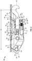
- FIG. 2 is a side cross-sectional view of the hook latch shown in FIG. 1 ;
- FIG. 3 is a bottom perspective view of the hook latch shown in FIG. 1 , but shown in an open position.
- a hook latch 10 having a housing 12 with a first end 14 and a second end 16 opposite the first end 14 .
- the housing 12 includes a first chamber 18 that extends from the first end 14 to a location intermediate the first and second ends 14 , 16 of the housing 12 .
- the first chamber 18 is sized and shaped to receive slidably a cylinder 20 .
- the cylinder 20 includes an elongated body 22 and a flange 24 located at one end of the body 22 .
- the flange 24 is circular in shape.
- the flange 24 includes a circular-shaped, centralized opening 25 formed therein.
- the body 22 of the cylinder 20 includes a hollow portion 26 that is sized and shaped to receive a compression spring 28 and a ball 30 positioned at one end of the compression spring 28 and proximate to the first end 14 of the housing 12 .
- the opening 25 of the flange 24 is in communication with the hollow portion 26 of the cylinder 20 .
- the compression spring 28 and the ball 30 nest in the hollow portion 26 of the cylinder 20 which is guided by the first chamber 18 .
- a surface of the ball 30 protrudes through the opening 25 of the flange 24 of the body 22 .
- the housing 12 includes a second chamber 32 that extends from the first end 14 to a point intermediate the first and second ends 14 , 16 .
- the second chamber 32 is positioned above the first chamber 18 relative to a longitudinal axis A-A of the housing 12 , as oriented and shown in the Figures.
- the second chamber 32 is sized and shaped to receive a hook 34 having a shaft 35 and a hook head 36 formed on an end of the shaft 35 .
- the second chamber 32 is sized and shaped to receive slidably the shaft 35 of the hook 34 .
- a catch pin 38 extends through one end of the shaft 35 of the hook 34 transversely to the longitudinal axis A-A of the housing 12 and protrudes outwardly from the housing 12 at opposite side portions 40 thereof (only one side portion 40 shown in FIG. 1 ).
- a star wheel 42 is positioned on the shaft 35 of the hook 34 and juxtaposed with the first end 14 of the housing 12 .
- the star wheel 42 includes a hollow, elongated shaft 43 which is sized and shaped to receive the shaft 35 of the hook 34 , a flange 44 located at one end of the shaft 35 , and an annular portion 45 extending outwardly from the shaft 35 and located proximate to the flange 44 .
- a portion of the flange 24 of the cylinder 20 is positioned between the annular portion 45 and the flange 44 of the star wheel 42 .
- the flange 44 of the star wheel 42 includes a face 46 with a first plurality of holes 48 that are each sized and shaped to receive the portion of the ball 30 exposed through the flange 24 of the cylinder 20 , and a circumferential edge 50 having a second plurality of holes 52 that are each sized and shaped to receive an adjusting tool.
- the holes of the first plurality of holes 48 are spaced apart from one another and form a circular pattern.
- the star wheel 42 is adjustable rotatably either clockwise or counterclockwise relative to the longitudinal axis A-A of the housing 12 .
- a portion of the flange 24 of the cylinder 20 is positioned and trapped between the flange 44 of the star wheel 42 and the annular portion 45 of the star wheel 42 and against a face of the annular portion 45 of the star wheel 42 while under the load of the compression spring 28 , while the ball 30 aligns with and engages one of the first plurality of holes 48 of the star wheel 42 .
- pressure from the compression spring 28 on the ball 30 prevents the star wheel 42 from rotating relative to the longitudinal axis A-A.
- the hook latch 10 includes a handle 54 attached rotatably to the second end 16 of the housing 12 by a pivot pin 56 extending through the second end 16 of the housing 12 and is moveable from a closed position to an open position, and vice-versa.
- the handle 54 includes a trigger 58 having detents 60 that engage the catch pin 38 when the handle 54 is in its closed position.
- the trigger 58 includes a trigger spring 59 .
- the handle 54 includes a pair of opposing side members 53 , each of which includes a slot 57 formed therethrough.
- each of the slots 57 is rounded rectangular-shaped and includes a first end 57 a and a second end 57 b opposite the first end 57 a .
- each of the slots 57 can be rectangular in shape or consist of any other suitable shape.
- the handle 54 includes a pair of links 61 and a cylindrical-shaped bushing 63 interconnecting one end of each of the links 61 to one another.
- one end 63 a of the bushing 63 extends through one of the slots 57 and the other end 63 b of the bushing 63 extends through the other one of the slots 57 .
- opposite ends of the links 61 are connected rotatably to the pivot pin 56 . When the handle 54 is in its closed position, the ends 63 a , 63 b of the bushing 63 are positioned proximate to the ends 57 a of the slots 57 .
- the detents 60 disengage the catch pin 38 to enable the handle 54 to move from the closed position to the open position, and, thus, retract the hook 34 from a first position to a second position.
- the slots 57 move over the ends 63 a , 63 b of the bushing until the ends 63 a , 63 b engage the ends 57 b of the slots 57 in order to rotate the links 61 , which, in turn, retract the hook 34 .
- a back spring 62 surrounds the pivot pin 56 in order to maintain the handle 54 in its open position.
- the mounting distance D of the hook 34 along the longitudinal axis A-A (i.e., measured from the center of the pivot pin 56 to a center point of the hook head 36 ) can be adjusted by turning the star wheel 42 with a standard tool, which engages one or more of the second plurality of holes 52 .
- turning the star wheel 42 moves the star wheel 42 in a longitudinal direction along axis A-A and drives the cylinder 20 along with it, while the ball 30 disengages one of the first plurality of holes 48 of the star wheel 42 and then engages another (e.g., the next adjacent one) of the first plurality of holes 48 under constant spring load from the compression spring 28 .
Abstract
Description
Claims (8)
Priority Applications (1)
| Application Number | Priority Date | Filing Date | Title |
|---|---|---|---|
| US15/251,535 US10760304B2 (en) | 2015-09-01 | 2016-08-30 | Adjustable hook latch |
Applications Claiming Priority (2)
| Application Number | Priority Date | Filing Date | Title |
|---|---|---|---|
| US201562212669P | 2015-09-01 | 2015-09-01 | |
| US15/251,535 US10760304B2 (en) | 2015-09-01 | 2016-08-30 | Adjustable hook latch |
Publications (2)
| Publication Number | Publication Date |
|---|---|
| US20170058568A1 US20170058568A1 (en) | 2017-03-02 |
| US10760304B2 true US10760304B2 (en) | 2020-09-01 |
Family
ID=56896805
Family Applications (1)
| Application Number | Title | Priority Date | Filing Date |
|---|---|---|---|
| US15/251,535 Active 2039-04-12 US10760304B2 (en) | 2015-09-01 | 2016-08-30 | Adjustable hook latch |
Country Status (5)
| Country | Link |
|---|---|
| US (1) | US10760304B2 (en) |
| EP (1) | EP3344833B1 (en) |
| CN (2) | CN106481169B (en) |
| ES (1) | ES2789576T3 (en) |
| WO (1) | WO2017040496A1 (en) |
Cited By (2)
| Publication number | Priority date | Publication date | Assignee | Title |
|---|---|---|---|---|
| US11072433B2 (en) * | 2018-09-12 | 2021-07-27 | Airbus Operations (S.A.S.) | Aircraft cowl locking system |
| US20220195765A1 (en) * | 2020-12-23 | 2022-06-23 | Rohr, Inc. | Encapsulated bearing block design for adjustable hook latch |
Families Citing this family (3)
| Publication number | Priority date | Publication date | Assignee | Title |
|---|---|---|---|---|
| ES2789576T3 (en) * | 2015-09-01 | 2020-10-26 | Arconic Inc | Adjustable hook closure |
| FR3093783B1 (en) * | 2019-03-14 | 2021-04-02 | Lisi Aerospace | Locking device for a threaded rod in a threaded tube |
| US11866189B2 (en) * | 2020-03-26 | 2024-01-09 | Hartwell Corporation | Latching system with movable anti-shear mechanism |
Citations (95)
| Publication number | Priority date | Publication date | Assignee | Title |
|---|---|---|---|---|
| US491908A (en) * | 1893-02-14 | Cornelius starz | ||
| DE202220C (en) | 1908-02-07 | 1908-09-29 | ||
| US1119321A (en) * | 1914-06-01 | 1914-12-01 | Frederick Schmidgall | Lock-keeper. |
| US1206342A (en) | 1915-06-22 | 1916-11-28 | Christina O Linborg | Sash-lock. |
| GB191493A (en) | 1921-10-15 | 1923-01-15 | Albert Hoare | Improvements in means for bolting doors |
| US2712955A (en) | 1952-09-15 | 1955-07-12 | Clark Hartwell | Draw-in type flush latch |
| US2726889A (en) | 1952-07-24 | 1955-12-13 | Melpar Inc | Latch |
| US2904141A (en) * | 1957-04-22 | 1959-09-15 | Clark Hartwell | Adjustable hook latch |
| US2927812A (en) | 1957-06-14 | 1960-03-08 | Clark Hartwell | Pivotable bolt latch |
| US2944848A (en) | 1958-02-10 | 1960-07-12 | Langley Corp | Latch |
| US3070395A (en) | 1960-09-13 | 1962-12-25 | Boeing Co | Latch mechanism |
| US3212746A (en) * | 1964-01-02 | 1965-10-19 | United Carr Inc | Locking clamping assembly |
| US3259412A (en) | 1963-12-17 | 1966-07-05 | Camloc Fastener Corp | Safety device for toggle latch |
| US3259411A (en) | 1963-12-17 | 1966-07-05 | Camloc Fastener Corp | Drawhook toggle latch |
| US3341239A (en) | 1964-07-23 | 1967-09-12 | Camloc Fastener Corp | Handle-operated shear pin latch |
| US3347578A (en) | 1964-11-18 | 1967-10-17 | Boeing Co | Flush-type safety latch |
| US3473693A (en) | 1968-08-26 | 1969-10-21 | Harvey Dental Specialty Co | Pressure chamber cover latch |
| US3664696A (en) * | 1971-01-15 | 1972-05-23 | Hartwell Corp | Latch adjuster |
| US3917327A (en) | 1974-02-05 | 1975-11-04 | Micro Devices Corp | Thermally actuated device and door latch means utilizing the same or the like |
| US4053177A (en) | 1976-06-08 | 1977-10-11 | Tridair Industries | Adjustable latch |
| GB1497982A (en) | 1975-05-28 | 1978-01-12 | Hesterberg & Soehne F | Sliding bolt fastening for a wall or tailboard of a utility vehicle |
| US4099751A (en) | 1976-08-26 | 1978-07-11 | Hartwell Corporation | Pin latch structure |
| US4116479A (en) | 1977-01-17 | 1978-09-26 | Hartwell Corporation | Adjustable flush mounted hook latch |
| US4130307A (en) | 1977-11-04 | 1978-12-19 | Hartwell Corporation | Pin latch and safety lock therefor |
| GB1537410A (en) | 1976-08-26 | 1978-12-29 | Hartwell Corp | Pin latch structure |
| FR2397503A1 (en) | 1977-07-13 | 1979-02-09 | Alsthom Atlantique | Hand lever operated bolt for door of public vehicle - has safety catch with rocking lever permitting movement of hand lever |
| US4183564A (en) * | 1978-03-01 | 1980-01-15 | Hartwell Corporation | Externally accessible adjuster for flush latches |
| US4220364A (en) | 1978-03-01 | 1980-09-02 | Hartwell Corporation | Flush type latches |
| US4361057A (en) * | 1980-02-28 | 1982-11-30 | John Sigan | Handlebar adjusting device |
| US4421349A (en) * | 1981-12-28 | 1983-12-20 | The Boeing Company | Cowling latch |
| US4478446A (en) * | 1979-12-17 | 1984-10-23 | Avibank Mfg., Inc. | Adjustable keeper assembly |
| USRE31935E (en) * | 1978-03-01 | 1985-07-02 | Hartwell Corporation | Externally accessible adjuster for flush latches |
| US4530529A (en) * | 1980-05-27 | 1985-07-23 | Hartwell Corporation | Externally accessible adjuster for flush latches |
| US4538843A (en) * | 1983-03-04 | 1985-09-03 | The Boeing Company | Preloaded latch |
| US4602812A (en) | 1983-05-20 | 1986-07-29 | Hartwell Corporation | Adjustable double hook latch |
| US4641868A (en) | 1984-08-22 | 1987-02-10 | Computerized Security Systems, Inc. | Recentering for shafts of locks and other mechanisms |
| US4691952A (en) * | 1986-10-06 | 1987-09-08 | Rexnord Inc. | Clutching adjustable keeper mechanism |
| US4798408A (en) * | 1986-04-23 | 1989-01-17 | Rexnord Inc. | Adjustable latching mechanism |
| US4826221A (en) | 1987-04-03 | 1989-05-02 | Hartwell Corporation | Tension and shear latching mechanism |
| US4828299A (en) | 1987-03-31 | 1989-05-09 | Hartwell Corporation | Latch |
| US4852923A (en) * | 1987-02-27 | 1989-08-01 | Rexnord Holdings Inc. | Vertical access adjustable latching mechanism externally accessible adjustable keeper mechanism |
| US4858970A (en) | 1987-12-18 | 1989-08-22 | Rexnord Holdings Inc. | Low profile latch |
| US4906037A (en) * | 1987-09-08 | 1990-03-06 | V.S.I. Corp. | Externally accessible, clutching adjustable keeper mechanism |
| US4911488A (en) | 1987-12-02 | 1990-03-27 | Kiekert Gmbh & Co. Kommanditgesellschaft | Motor-vehicle door latch with built-in switch |
| US5016931A (en) * | 1989-06-20 | 1991-05-21 | The Hartwell Corporation | Latching mechanism having a pre-adjusted load |
| US5152926A (en) | 1989-06-02 | 1992-10-06 | Union Carbide Chemicals & Plastics Technology Corporation | Refrigerant lubricant compositions |
| US5177988A (en) * | 1991-07-31 | 1993-01-12 | Bushnell Raymond B | Security lock mechanism incorporating hydraulic dead locking |
| US5228730A (en) | 1992-09-02 | 1993-07-20 | Security People, Inc. | Apparatus for converting mechanical locks to operate electrically using momentary power |
| US5341752A (en) | 1992-06-04 | 1994-08-30 | Brian Hambleton | Security safe with improved door locking features |
| US5609373A (en) | 1992-02-20 | 1997-03-11 | Southco, Inc. | Lever latch |
| US5620212A (en) * | 1995-08-28 | 1997-04-15 | Hartwell Corporation | Low profile hook latch assembly |
| US5660295A (en) | 1995-03-06 | 1997-08-26 | Gpe Controls, Inc. | Covers for gauging and sampling openings |
| US5765883A (en) * | 1995-07-14 | 1998-06-16 | Hartwell Corporation | Adjustable pressure relief latch |
| DE29807738U1 (en) | 1998-04-29 | 1998-07-23 | Hesterberg & Soehne Gmbh & Co | Lateral edging for side walls of commercial vehicles with an integrated bolt lock |
| US5984382A (en) * | 1998-03-13 | 1999-11-16 | Hartwell Corporation | Extended reach latch |
| US6123370A (en) | 1999-03-31 | 2000-09-26 | Hartwell Corporation | Increased strength dogging mechanism |
| EP1091059A2 (en) | 1999-10-05 | 2001-04-11 | Hartwell Corporation | Latch with sensor providing visual indication of the latch position |
| US20020000726A1 (en) | 1998-07-11 | 2002-01-03 | Albert Zintler | Locking device in particular for motor vehicle doors |
| US6343815B1 (en) | 2000-10-04 | 2002-02-05 | Hartwell Corporation | Cinch-up latch |
| US6361090B1 (en) | 2000-01-18 | 2002-03-26 | Fang-Yi Fan | Lock apparatus |
| US6382690B1 (en) * | 2000-09-27 | 2002-05-07 | Hartwell Corporation | Keeper mechanism |
| US6513841B1 (en) * | 2000-10-10 | 2003-02-04 | Hartwell Corporation | Blowout latch |
| US6755448B2 (en) * | 2001-06-20 | 2004-06-29 | Hartwell Corporation | Blowout latch |
| FR2852049A1 (en) | 2003-03-04 | 2004-09-10 | Laperche Sa | Locking assembly for service pipes of train, has lock with locking unit movable between locking and unlocking positions, and preventing blocking bolt from taking up unblocking position in locking position |
| US6866226B2 (en) * | 2001-10-04 | 2005-03-15 | Hartwell Corporation | Pressure responsive blowout latch |
| US20050087996A1 (en) | 2003-10-27 | 2005-04-28 | Jackson Frank T. | Rotary latch mechanism |
| US7029038B2 (en) | 2001-12-07 | 2006-04-18 | Attwood Mobile Products, Inc. | Egress window latching mechanism |
| US20060214431A1 (en) | 2005-03-25 | 2006-09-28 | Helsley Thomas J | Latch mechanism |
| US7156429B2 (en) | 2002-10-30 | 2007-01-02 | Lars Eriksson | Retainer for an over-centre fastener |
| US20080129056A1 (en) | 2006-11-30 | 2008-06-05 | Hartwell Corporation | Command Latch and Pin Latch System |
| EP2031157A1 (en) | 2007-08-29 | 2009-03-04 | Enzo Anselmi | Safety lockset |
| US7504601B2 (en) | 2003-07-15 | 2009-03-17 | Arvinmeritor Light Vehicle Systems - France | Sensor module for releasing vehicle windows and the like |
| WO2010033026A1 (en) | 2008-09-19 | 2010-03-25 | Newthex Ned. B.V. | Locking element and locking system for a ship's door, ship's window or ship's hatch |
| US7857362B2 (en) | 2004-11-02 | 2010-12-28 | Valeo Securite Habitacle | Lock for two-notch locking bolt comprising a single switch |
| WO2010149905A1 (en) | 2009-06-22 | 2010-12-29 | Airbus Operations | Aircraft latch comprising a hook and a handle |
| US20110109103A1 (en) | 2009-11-12 | 2011-05-12 | Cessna Aircraft Company | Fuselage Door Self-Locking Pin Latch |
| US8016327B2 (en) * | 2006-08-09 | 2011-09-13 | Hartwell Corporation | Bifurcated latching system |
| CN102191876A (en) | 2010-03-18 | 2011-09-21 | 美铝公司 | Latch with adjustable handle |
| US8113551B2 (en) * | 2007-06-13 | 2012-02-14 | Avibank Manufacturing, Inc. | Radome latch and keeper |
| EP2444575A1 (en) | 2010-10-25 | 2012-04-25 | Lisi Aerospace SAS | Pawl lock provided with a positioning device and method for installing such a lock |
| US20120242096A1 (en) * | 2009-12-04 | 2012-09-27 | Hartwell Corporation | Pressure relief latch mechanism |
| CN202926055U (en) | 2011-12-02 | 2013-05-08 | 美铝公司 | Pin type bolt lock |
| US8479543B2 (en) | 2009-12-01 | 2013-07-09 | Zaifu Yang | Door locking system with an idle handle |
| US20130328326A1 (en) | 2012-06-11 | 2013-12-12 | Lisi Aerospace | Hook latch |
| US8646819B2 (en) | 2011-10-31 | 2014-02-11 | Alcoa Inc. | Rotary-handle latch |
| US8727390B2 (en) | 2010-02-09 | 2014-05-20 | Alcoa Inc. | Side-driven action pin latch |
| US20150184544A1 (en) | 2014-01-02 | 2015-07-02 | Airbus Operations (Sas) | Fan cowl locking system |
| US20150184543A1 (en) | 2014-01-02 | 2015-07-02 | Airbus Operations (Sas) | Fan cowl locking system |
| US9273488B1 (en) * | 2013-07-15 | 2016-03-01 | Avibank Manufacturing, Inc. | Positive locking keeper |
| US9353559B2 (en) * | 2014-04-22 | 2016-05-31 | Airbus Operations (Sas) | Latching system for securing two components |
| CN206053629U (en) | 2015-09-01 | 2017-03-29 | 美铝公司 | Adjustable hook breech lock |
| US10173782B2 (en) * | 2015-03-13 | 2019-01-08 | Qrp, Inc. | Toggle link latch |
| US10240389B2 (en) * | 2015-09-30 | 2019-03-26 | Arconic Inc. | Pressure relief door |
| US10309126B2 (en) * | 2016-01-21 | 2019-06-04 | Arconic Inc. | Pawl latch |
| US10443279B2 (en) * | 2015-09-01 | 2019-10-15 | Hartwell Corporation | Single link hook latch |
-
2016
- 2016-08-30 ES ES16763658T patent/ES2789576T3/en active Active
- 2016-08-30 US US15/251,535 patent/US10760304B2/en active Active
- 2016-08-30 WO PCT/US2016/049434 patent/WO2017040496A1/en unknown
- 2016-08-30 EP EP16763658.8A patent/EP3344833B1/en active Active
- 2016-08-31 CN CN201610792212.7A patent/CN106481169B/en active Active
- 2016-08-31 CN CN201621026074.3U patent/CN206053629U/en not_active Withdrawn - After Issue
Patent Citations (107)
| Publication number | Priority date | Publication date | Assignee | Title |
|---|---|---|---|---|
| US491908A (en) * | 1893-02-14 | Cornelius starz | ||
| DE202220C (en) | 1908-02-07 | 1908-09-29 | ||
| US1119321A (en) * | 1914-06-01 | 1914-12-01 | Frederick Schmidgall | Lock-keeper. |
| US1206342A (en) | 1915-06-22 | 1916-11-28 | Christina O Linborg | Sash-lock. |
| GB191493A (en) | 1921-10-15 | 1923-01-15 | Albert Hoare | Improvements in means for bolting doors |
| US2726889A (en) | 1952-07-24 | 1955-12-13 | Melpar Inc | Latch |
| US2712955A (en) | 1952-09-15 | 1955-07-12 | Clark Hartwell | Draw-in type flush latch |
| US2904141A (en) * | 1957-04-22 | 1959-09-15 | Clark Hartwell | Adjustable hook latch |
| US2927812A (en) | 1957-06-14 | 1960-03-08 | Clark Hartwell | Pivotable bolt latch |
| US2944848A (en) | 1958-02-10 | 1960-07-12 | Langley Corp | Latch |
| US3070395A (en) | 1960-09-13 | 1962-12-25 | Boeing Co | Latch mechanism |
| US3259412A (en) | 1963-12-17 | 1966-07-05 | Camloc Fastener Corp | Safety device for toggle latch |
| US3259411A (en) | 1963-12-17 | 1966-07-05 | Camloc Fastener Corp | Drawhook toggle latch |
| US3212746A (en) * | 1964-01-02 | 1965-10-19 | United Carr Inc | Locking clamping assembly |
| US3341239A (en) | 1964-07-23 | 1967-09-12 | Camloc Fastener Corp | Handle-operated shear pin latch |
| US3347578A (en) | 1964-11-18 | 1967-10-17 | Boeing Co | Flush-type safety latch |
| US3473693A (en) | 1968-08-26 | 1969-10-21 | Harvey Dental Specialty Co | Pressure chamber cover latch |
| US3664696A (en) * | 1971-01-15 | 1972-05-23 | Hartwell Corp | Latch adjuster |
| US3917327A (en) | 1974-02-05 | 1975-11-04 | Micro Devices Corp | Thermally actuated device and door latch means utilizing the same or the like |
| GB1497982A (en) | 1975-05-28 | 1978-01-12 | Hesterberg & Soehne F | Sliding bolt fastening for a wall or tailboard of a utility vehicle |
| US4053177A (en) | 1976-06-08 | 1977-10-11 | Tridair Industries | Adjustable latch |
| GB1537410A (en) | 1976-08-26 | 1978-12-29 | Hartwell Corp | Pin latch structure |
| US4099751A (en) | 1976-08-26 | 1978-07-11 | Hartwell Corporation | Pin latch structure |
| US4116479A (en) | 1977-01-17 | 1978-09-26 | Hartwell Corporation | Adjustable flush mounted hook latch |
| FR2397503A1 (en) | 1977-07-13 | 1979-02-09 | Alsthom Atlantique | Hand lever operated bolt for door of public vehicle - has safety catch with rocking lever permitting movement of hand lever |
| US4130307A (en) | 1977-11-04 | 1978-12-19 | Hartwell Corporation | Pin latch and safety lock therefor |
| US4183564A (en) * | 1978-03-01 | 1980-01-15 | Hartwell Corporation | Externally accessible adjuster for flush latches |
| US4220364A (en) | 1978-03-01 | 1980-09-02 | Hartwell Corporation | Flush type latches |
| USRE31935E (en) * | 1978-03-01 | 1985-07-02 | Hartwell Corporation | Externally accessible adjuster for flush latches |
| US4478446A (en) * | 1979-12-17 | 1984-10-23 | Avibank Mfg., Inc. | Adjustable keeper assembly |
| US4361057A (en) * | 1980-02-28 | 1982-11-30 | John Sigan | Handlebar adjusting device |
| US4530529A (en) * | 1980-05-27 | 1985-07-23 | Hartwell Corporation | Externally accessible adjuster for flush latches |
| US4421349A (en) * | 1981-12-28 | 1983-12-20 | The Boeing Company | Cowling latch |
| US4538843A (en) * | 1983-03-04 | 1985-09-03 | The Boeing Company | Preloaded latch |
| US4602812A (en) | 1983-05-20 | 1986-07-29 | Hartwell Corporation | Adjustable double hook latch |
| US4641868A (en) | 1984-08-22 | 1987-02-10 | Computerized Security Systems, Inc. | Recentering for shafts of locks and other mechanisms |
| US4798408A (en) * | 1986-04-23 | 1989-01-17 | Rexnord Inc. | Adjustable latching mechanism |
| US4691952A (en) * | 1986-10-06 | 1987-09-08 | Rexnord Inc. | Clutching adjustable keeper mechanism |
| US4852923A (en) * | 1987-02-27 | 1989-08-01 | Rexnord Holdings Inc. | Vertical access adjustable latching mechanism externally accessible adjustable keeper mechanism |
| US4828299A (en) | 1987-03-31 | 1989-05-09 | Hartwell Corporation | Latch |
| US4826221A (en) | 1987-04-03 | 1989-05-02 | Hartwell Corporation | Tension and shear latching mechanism |
| US4906037A (en) * | 1987-09-08 | 1990-03-06 | V.S.I. Corp. | Externally accessible, clutching adjustable keeper mechanism |
| US4911488A (en) | 1987-12-02 | 1990-03-27 | Kiekert Gmbh & Co. Kommanditgesellschaft | Motor-vehicle door latch with built-in switch |
| US4858970A (en) | 1987-12-18 | 1989-08-22 | Rexnord Holdings Inc. | Low profile latch |
| US5152926A (en) | 1989-06-02 | 1992-10-06 | Union Carbide Chemicals & Plastics Technology Corporation | Refrigerant lubricant compositions |
| US5016931A (en) * | 1989-06-20 | 1991-05-21 | The Hartwell Corporation | Latching mechanism having a pre-adjusted load |
| US5177988A (en) * | 1991-07-31 | 1993-01-12 | Bushnell Raymond B | Security lock mechanism incorporating hydraulic dead locking |
| US5609373A (en) | 1992-02-20 | 1997-03-11 | Southco, Inc. | Lever latch |
| US5664813A (en) | 1992-02-20 | 1997-09-09 | Southco, Inc. | Lever latch |
| US5341752A (en) | 1992-06-04 | 1994-08-30 | Brian Hambleton | Security safe with improved door locking features |
| US5228730A (en) | 1992-09-02 | 1993-07-20 | Security People, Inc. | Apparatus for converting mechanical locks to operate electrically using momentary power |
| US5660295A (en) | 1995-03-06 | 1997-08-26 | Gpe Controls, Inc. | Covers for gauging and sampling openings |
| US5765883A (en) * | 1995-07-14 | 1998-06-16 | Hartwell Corporation | Adjustable pressure relief latch |
| US5620212A (en) * | 1995-08-28 | 1997-04-15 | Hartwell Corporation | Low profile hook latch assembly |
| US5984382A (en) * | 1998-03-13 | 1999-11-16 | Hartwell Corporation | Extended reach latch |
| DE29807738U1 (en) | 1998-04-29 | 1998-07-23 | Hesterberg & Soehne Gmbh & Co | Lateral edging for side walls of commercial vehicles with an integrated bolt lock |
| US20020000726A1 (en) | 1998-07-11 | 2002-01-03 | Albert Zintler | Locking device in particular for motor vehicle doors |
| US20020060459A1 (en) | 1998-07-11 | 2002-05-23 | Mannesmann Vdo Ag | Locking device, in particular for motor vehicle doors |
| US6123370A (en) | 1999-03-31 | 2000-09-26 | Hartwell Corporation | Increased strength dogging mechanism |
| EP1091059A2 (en) | 1999-10-05 | 2001-04-11 | Hartwell Corporation | Latch with sensor providing visual indication of the latch position |
| US6361090B1 (en) | 2000-01-18 | 2002-03-26 | Fang-Yi Fan | Lock apparatus |
| US6382690B1 (en) * | 2000-09-27 | 2002-05-07 | Hartwell Corporation | Keeper mechanism |
| US6343815B1 (en) | 2000-10-04 | 2002-02-05 | Hartwell Corporation | Cinch-up latch |
| US6513841B1 (en) * | 2000-10-10 | 2003-02-04 | Hartwell Corporation | Blowout latch |
| US6755448B2 (en) * | 2001-06-20 | 2004-06-29 | Hartwell Corporation | Blowout latch |
| US6866226B2 (en) * | 2001-10-04 | 2005-03-15 | Hartwell Corporation | Pressure responsive blowout latch |
| US7029038B2 (en) | 2001-12-07 | 2006-04-18 | Attwood Mobile Products, Inc. | Egress window latching mechanism |
| US7156429B2 (en) | 2002-10-30 | 2007-01-02 | Lars Eriksson | Retainer for an over-centre fastener |
| FR2852049A1 (en) | 2003-03-04 | 2004-09-10 | Laperche Sa | Locking assembly for service pipes of train, has lock with locking unit movable between locking and unlocking positions, and preventing blocking bolt from taking up unblocking position in locking position |
| US7504601B2 (en) | 2003-07-15 | 2009-03-17 | Arvinmeritor Light Vehicle Systems - France | Sensor module for releasing vehicle windows and the like |
| US20050087996A1 (en) | 2003-10-27 | 2005-04-28 | Jackson Frank T. | Rotary latch mechanism |
| US6913297B2 (en) | 2003-10-27 | 2005-07-05 | Hartwell Corporation | Rotary latch mechanism |
| US7857362B2 (en) | 2004-11-02 | 2010-12-28 | Valeo Securite Habitacle | Lock for two-notch locking bolt comprising a single switch |
| US20060214431A1 (en) | 2005-03-25 | 2006-09-28 | Helsley Thomas J | Latch mechanism |
| US8016327B2 (en) * | 2006-08-09 | 2011-09-13 | Hartwell Corporation | Bifurcated latching system |
| US20080129056A1 (en) | 2006-11-30 | 2008-06-05 | Hartwell Corporation | Command Latch and Pin Latch System |
| US8925979B2 (en) * | 2006-11-30 | 2015-01-06 | Hartwell Corporation | Command latch and pin latch system |
| US8113551B2 (en) * | 2007-06-13 | 2012-02-14 | Avibank Manufacturing, Inc. | Radome latch and keeper |
| EP2031157A1 (en) | 2007-08-29 | 2009-03-04 | Enzo Anselmi | Safety lockset |
| WO2010033026A1 (en) | 2008-09-19 | 2010-03-25 | Newthex Ned. B.V. | Locking element and locking system for a ship's door, ship's window or ship's hatch |
| WO2010149905A1 (en) | 2009-06-22 | 2010-12-29 | Airbus Operations | Aircraft latch comprising a hook and a handle |
| US20120102842A1 (en) | 2009-06-22 | 2012-05-03 | Airbus Operations (S.A.S) | Aircraft latch comprising a hook and a handle |
| US8864189B2 (en) * | 2009-06-22 | 2014-10-21 | Airbus Operations (S.A.S.) | Aircraft latch comprising a hook and a handle |
| US20110109103A1 (en) | 2009-11-12 | 2011-05-12 | Cessna Aircraft Company | Fuselage Door Self-Locking Pin Latch |
| US8479543B2 (en) | 2009-12-01 | 2013-07-09 | Zaifu Yang | Door locking system with an idle handle |
| US20120242096A1 (en) * | 2009-12-04 | 2012-09-27 | Hartwell Corporation | Pressure relief latch mechanism |
| US8727390B2 (en) | 2010-02-09 | 2014-05-20 | Alcoa Inc. | Side-driven action pin latch |
| US20110227350A1 (en) | 2010-03-18 | 2011-09-22 | Thai Do | Latch with adjustable handle |
| CN102191876A (en) | 2010-03-18 | 2011-09-21 | 美铝公司 | Latch with adjustable handle |
| US8864185B2 (en) * | 2010-03-18 | 2014-10-21 | Alcoa Inc. | Latch with adjustable handle |
| EP2444575A1 (en) | 2010-10-25 | 2012-04-25 | Lisi Aerospace SAS | Pawl lock provided with a positioning device and method for installing such a lock |
| US20120151724A1 (en) | 2010-10-25 | 2012-06-21 | Defrance Vincent | Hook latch fitted with a positioning device and a method for assembling such a latch |
| US9567784B2 (en) * | 2010-10-25 | 2017-02-14 | Lisi Aerospace | Hook latch fitted with a positioning device and a method for assembling such a latch |
| US8646819B2 (en) | 2011-10-31 | 2014-02-11 | Alcoa Inc. | Rotary-handle latch |
| CN202926055U (en) | 2011-12-02 | 2013-05-08 | 美铝公司 | Pin type bolt lock |
| EP2674362A1 (en) | 2012-06-11 | 2013-12-18 | Lisi Aerospace | Pawl lock |
| US20130328326A1 (en) | 2012-06-11 | 2013-12-12 | Lisi Aerospace | Hook latch |
| US9677306B2 (en) * | 2012-06-11 | 2017-06-13 | Lisi Aerospace | Hook latch |
| US9273488B1 (en) * | 2013-07-15 | 2016-03-01 | Avibank Manufacturing, Inc. | Positive locking keeper |
| US20150184544A1 (en) | 2014-01-02 | 2015-07-02 | Airbus Operations (Sas) | Fan cowl locking system |
| US20150184543A1 (en) | 2014-01-02 | 2015-07-02 | Airbus Operations (Sas) | Fan cowl locking system |
| US9353559B2 (en) * | 2014-04-22 | 2016-05-31 | Airbus Operations (Sas) | Latching system for securing two components |
| US10173782B2 (en) * | 2015-03-13 | 2019-01-08 | Qrp, Inc. | Toggle link latch |
| CN206053629U (en) | 2015-09-01 | 2017-03-29 | 美铝公司 | Adjustable hook breech lock |
| US10443279B2 (en) * | 2015-09-01 | 2019-10-15 | Hartwell Corporation | Single link hook latch |
| US10240389B2 (en) * | 2015-09-30 | 2019-03-26 | Arconic Inc. | Pressure relief door |
| US10309126B2 (en) * | 2016-01-21 | 2019-06-04 | Arconic Inc. | Pawl latch |
Non-Patent Citations (14)
| Title |
|---|
| Aerospace Latching Systems, Alcoa Fastening Systems, http://www.alcoa.com/fastening_systems/aerospace/en/product.asp?cat_id=213&prod_id=500,pp. I1-I2, 159-160, and i-iii (8 pages). |
| Alcoa Camloc/RAM Catalog, pp. I-13 to I-17 (3 pages). |
| Alcoa Fastening Systems, Document TL22028 Rev. P, dated Jun. 18, 2015 (2 pages). |
| English-language translation of WO 2010/149905 A1 (8 pages). |
| Fairchild Fasteners, Aerospace Mechanisms, "RAM™ Aerospace Latch Mechanism", 2000 (4 pages). |
| International Search Report and Written Opinion dated Dec. 29, 2011, issued by the European Patent Office in connection with International Patent Application No. PCT/US2011/027871 entitled "Latch With Adjustable Handle" (17 pages). |
| International Search Report and Written Opinion dated Feb. 25, 2013, issued by the European Patent Office in connection with International Patent Application No. PCT/US2012/066039 entitled "Pin Latch With Detection Device and Movable Catch-Pin and Intermediate Position With Automatic Return Mechanism" (15 pages). |
| International Search Report and Written Opinion dated Jan. 18, 2013, issued by the European Patent Office in connection with International Patent Application No. PCT/US2012/059206 entitled "Rotary-Handle Latch" (9 pages). |
| International Search Report and Written Opinion dated Jul. 15, 2011, issued by the European Patent Office in connection with International Patent Application No. PCT/US2011/027671 entitled "Latch With Adjustable Handle" (8 pages). |
| International Search Report and Written Opinion dated Jul. 20, 2012, issued by the European Patent Office in connection with International Patent Application No. PCT/US2012/028418 entitled "Pin Latch Having Intermediate Position" (13 pages). |
| International Search Report and Written Opinion dated Jun. 7, 2011, issued by the European Patent Office in connection with International Patent Application No. PCT/US2011/024031 entitled "Side-Driven Action Pin Latch" (9 pages). |
| International Search Report and Written Opinion dated Jun. 9, 2016, issued by the European Patent Office in connection with International Patent Application No. PCT/US2016/024836 (13 pages). |
| International Search Report and Written Opinion dated Nov. 23, 2016, issued by the European Patent Office in International (PCT) Application No. PCT/US2016/049434 filed Aug. 30, 2016 (10 pages). |
| Rotary Latch #TL18261, Alcoa Fastening Systems, Mar. 2005 (1 page). |
Cited By (3)
| Publication number | Priority date | Publication date | Assignee | Title |
|---|---|---|---|---|
| US11072433B2 (en) * | 2018-09-12 | 2021-07-27 | Airbus Operations (S.A.S.) | Aircraft cowl locking system |
| US20220195765A1 (en) * | 2020-12-23 | 2022-06-23 | Rohr, Inc. | Encapsulated bearing block design for adjustable hook latch |
| US11668124B2 (en) * | 2020-12-23 | 2023-06-06 | Rohr, Inc. | Encapsulated bearing block design for adjustable hook latch |
Also Published As
| Publication number | Publication date |
|---|---|
| ES2789576T3 (en) | 2020-10-26 |
| EP3344833B1 (en) | 2020-04-15 |
| CN106481169A (en) | 2017-03-08 |
| WO2017040496A1 (en) | 2017-03-09 |
| EP3344833A1 (en) | 2018-07-11 |
| CN106481169B (en) | 2018-03-06 |
| CN206053629U (en) | 2017-03-29 |
| US20170058568A1 (en) | 2017-03-02 |
Similar Documents
| Publication | Publication Date | Title |
|---|---|---|
| US10760304B2 (en) | Adjustable hook latch | |
| US8763206B1 (en) | Hinge | |
| US7540140B1 (en) | Shackle apparatus | |
| US9764183B2 (en) | Quick-release clamp assembly for weightlifting bar | |
| ITVR20130006A1 (en) | ADJUSTABLE SPHERICAL JOINT | |
| KR20200003886A (en) | Restraining devices | |
| US10309126B2 (en) | Pawl latch | |
| EP3278745A3 (en) | Adapter assemblies for surgical devices | |
| US10780592B2 (en) | Knife | |
| US20160368125A1 (en) | Pliers for distortion prevention tool | |
| US8434750B2 (en) | Positioning device for workpieces | |
| US20160146571A1 (en) | Multi-Axis Swivel Connector | |
| US9200474B1 (en) | Locking device | |
| US10369591B2 (en) | Pipe painter assembly | |
| US10478976B2 (en) | Handle and knife having the same | |
| US9848862B2 (en) | Retractor blade assembly | |
| US9873188B1 (en) | Pliers for loop clamp | |
| US11041331B2 (en) | Latch having tool recess in trigger | |
| US918062A (en) | Extensible shaft-coupling. | |
| US20180103732A1 (en) | Double lock mechanism | |
| US20130167866A1 (en) | Hair accessory | |
| JP2017500181A5 (en) | ||
| GB2539101B (en) | Pliers for loop clamp | |
| WO2020086915A3 (en) | Handed spiral slotted scalpet array | |
| TWI445896B (en) | Mobile platform with six degrees of freedom |
Legal Events
| Date | Code | Title | Description |
|---|---|---|---|
| AS | Assignment |
Owner name: ALCOA INC., PENNSYLVANIA Free format text: ASSIGNMENT OF ASSIGNORS INTEREST;ASSIGNOR:DO, THAI;REEL/FRAME:039993/0444 Effective date: 20151008 |
|
| AS | Assignment |
Owner name: ARCONIC INC., PENNSYLVANIA Free format text: CHANGE OF NAME;ASSIGNOR:ALCOA INC.;REEL/FRAME:040599/0309 Effective date: 20161031 |
|
| STPP | Information on status: patent application and granting procedure in general |
Free format text: DOCKETED NEW CASE - READY FOR EXAMINATION |
|
| STPP | Information on status: patent application and granting procedure in general |
Free format text: NON FINAL ACTION MAILED |
|
| STPP | Information on status: patent application and granting procedure in general |
Free format text: NOTICE OF ALLOWANCE MAILED -- APPLICATION RECEIVED IN OFFICE OF PUBLICATIONS |
|
| AS | Assignment |
Owner name: HOWMET AEROSPACE INC., PENNSYLVANIA Free format text: CHANGE OF NAME;ASSIGNOR:ARCONIC INC.;REEL/FRAME:053086/0762 Effective date: 20200331 |
|
| STPP | Information on status: patent application and granting procedure in general |
Free format text: PUBLICATIONS -- ISSUE FEE PAYMENT RECEIVED |
|
| STCF | Information on status: patent grant |
Free format text: PATENTED CASE |
|
| MAFP | Maintenance fee payment |
Free format text: PAYMENT OF MAINTENANCE FEE, 4TH YEAR, LARGE ENTITY (ORIGINAL EVENT CODE: M1551); ENTITY STATUS OF PATENT OWNER: LARGE ENTITY Year of fee payment: 4 |