EP4245450A1 - Method for fabricating additively manufactured object - Google Patents
Method for fabricating additively manufactured object Download PDFInfo
- Publication number
- EP4245450A1 EP4245450A1 EP21917647.6A EP21917647A EP4245450A1 EP 4245450 A1 EP4245450 A1 EP 4245450A1 EP 21917647 A EP21917647 A EP 21917647A EP 4245450 A1 EP4245450 A1 EP 4245450A1
- Authority
- EP
- European Patent Office
- Prior art keywords
- correction
- height
- torch
- weld beads
- correction ratio
- Prior art date
- Legal status (The legal status is an assumption and is not a legal conclusion. Google has not performed a legal analysis and makes no representation as to the accuracy of the status listed.)
- Pending
Links
- 238000000034 method Methods 0.000 title claims description 30
- 238000012937 correction Methods 0.000 claims abstract description 143
- 239000011324 bead Substances 0.000 claims abstract description 81
- 238000003466 welding Methods 0.000 claims abstract description 65
- 238000012545 processing Methods 0.000 claims abstract description 39
- 238000000151 deposition Methods 0.000 claims abstract description 33
- 230000008021 deposition Effects 0.000 claims abstract description 23
- 238000005259 measurement Methods 0.000 claims abstract description 20
- 238000004519 manufacturing process Methods 0.000 claims description 28
- 239000000945 filler Substances 0.000 claims description 18
- 239000000463 material Substances 0.000 claims description 18
- 230000008018 melting Effects 0.000 claims description 5
- 238000002844 melting Methods 0.000 claims description 5
- 238000010586 diagram Methods 0.000 description 6
- 229910000831 Steel Inorganic materials 0.000 description 5
- 238000010438 heat treatment Methods 0.000 description 5
- 239000002184 metal Substances 0.000 description 5
- 229910052751 metal Inorganic materials 0.000 description 5
- 239000010959 steel Substances 0.000 description 5
- 230000015572 biosynthetic process Effects 0.000 description 3
- 238000006243 chemical reaction Methods 0.000 description 3
- CURLTUGMZLYLDI-UHFFFAOYSA-N Carbon dioxide Chemical compound O=C=O CURLTUGMZLYLDI-UHFFFAOYSA-N 0.000 description 2
- 229910001209 Low-carbon steel Inorganic materials 0.000 description 2
- 238000010894 electron beam technology Methods 0.000 description 2
- 239000007769 metal material Substances 0.000 description 2
- 239000007787 solid Substances 0.000 description 2
- RTAQQCXQSZGOHL-UHFFFAOYSA-N Titanium Chemical compound [Ti] RTAQQCXQSZGOHL-UHFFFAOYSA-N 0.000 description 1
- 230000037237 body shape Effects 0.000 description 1
- 229910002092 carbon dioxide Inorganic materials 0.000 description 1
- 239000001569 carbon dioxide Substances 0.000 description 1
- 230000000694 effects Effects 0.000 description 1
- 238000002474 experimental method Methods 0.000 description 1
- 238000012423 maintenance Methods 0.000 description 1
- 239000000155 melt Substances 0.000 description 1
- 230000003647 oxidation Effects 0.000 description 1
- 238000007254 oxidation reaction Methods 0.000 description 1
- 239000000843 powder Substances 0.000 description 1
- 238000012827 research and development Methods 0.000 description 1
- 230000035945 sensitivity Effects 0.000 description 1
- 238000007778 shielded metal arc welding Methods 0.000 description 1
- 238000003860 storage Methods 0.000 description 1
- 239000010936 titanium Substances 0.000 description 1
- 229910052719 titanium Inorganic materials 0.000 description 1
- 230000001052 transient effect Effects 0.000 description 1
Images


Classifications
-
- B—PERFORMING OPERATIONS; TRANSPORTING
- B23—MACHINE TOOLS; METAL-WORKING NOT OTHERWISE PROVIDED FOR
- B23K—SOLDERING OR UNSOLDERING; WELDING; CLADDING OR PLATING BY SOLDERING OR WELDING; CUTTING BY APPLYING HEAT LOCALLY, e.g. FLAME CUTTING; WORKING BY LASER BEAM
- B23K9/00—Arc welding or cutting
- B23K9/04—Welding for other purposes than joining, e.g. built-up welding
-
- B—PERFORMING OPERATIONS; TRANSPORTING
- B33—ADDITIVE MANUFACTURING TECHNOLOGY
- B33Y—ADDITIVE MANUFACTURING, i.e. MANUFACTURING OF THREE-DIMENSIONAL [3-D] OBJECTS BY ADDITIVE DEPOSITION, ADDITIVE AGGLOMERATION OR ADDITIVE LAYERING, e.g. BY 3-D PRINTING, STEREOLITHOGRAPHY OR SELECTIVE LASER SINTERING
- B33Y10/00—Processes of additive manufacturing
-
- B—PERFORMING OPERATIONS; TRANSPORTING
- B22—CASTING; POWDER METALLURGY
- B22F—WORKING METALLIC POWDER; MANUFACTURE OF ARTICLES FROM METALLIC POWDER; MAKING METALLIC POWDER; APPARATUS OR DEVICES SPECIALLY ADAPTED FOR METALLIC POWDER
- B22F10/00—Additive manufacturing of workpieces or articles from metallic powder
- B22F10/20—Direct sintering or melting
- B22F10/22—Direct deposition of molten metal
-
- B—PERFORMING OPERATIONS; TRANSPORTING
- B22—CASTING; POWDER METALLURGY
- B22F—WORKING METALLIC POWDER; MANUFACTURE OF ARTICLES FROM METALLIC POWDER; MAKING METALLIC POWDER; APPARATUS OR DEVICES SPECIALLY ADAPTED FOR METALLIC POWDER
- B22F10/00—Additive manufacturing of workpieces or articles from metallic powder
- B22F10/30—Process control
- B22F10/38—Process control to achieve specific product aspects, e.g. surface smoothness, density, porosity or hollow structures
-
- B—PERFORMING OPERATIONS; TRANSPORTING
- B22—CASTING; POWDER METALLURGY
- B22F—WORKING METALLIC POWDER; MANUFACTURE OF ARTICLES FROM METALLIC POWDER; MAKING METALLIC POWDER; APPARATUS OR DEVICES SPECIALLY ADAPTED FOR METALLIC POWDER
- B22F12/00—Apparatus or devices specially adapted for additive manufacturing; Auxiliary means for additive manufacturing; Combinations of additive manufacturing apparatus or devices with other processing apparatus or devices
- B22F12/90—Means for process control, e.g. cameras or sensors
-
- B—PERFORMING OPERATIONS; TRANSPORTING
- B23—MACHINE TOOLS; METAL-WORKING NOT OTHERWISE PROVIDED FOR
- B23K—SOLDERING OR UNSOLDERING; WELDING; CLADDING OR PLATING BY SOLDERING OR WELDING; CUTTING BY APPLYING HEAT LOCALLY, e.g. FLAME CUTTING; WORKING BY LASER BEAM
- B23K26/00—Working by laser beam, e.g. welding, cutting or boring
- B23K26/02—Positioning or observing the workpiece, e.g. with respect to the point of impact; Aligning, aiming or focusing the laser beam
- B23K26/03—Observing, e.g. monitoring, the workpiece
- B23K26/032—Observing, e.g. monitoring, the workpiece using optical means
-
- B—PERFORMING OPERATIONS; TRANSPORTING
- B23—MACHINE TOOLS; METAL-WORKING NOT OTHERWISE PROVIDED FOR
- B23K—SOLDERING OR UNSOLDERING; WELDING; CLADDING OR PLATING BY SOLDERING OR WELDING; CUTTING BY APPLYING HEAT LOCALLY, e.g. FLAME CUTTING; WORKING BY LASER BEAM
- B23K26/00—Working by laser beam, e.g. welding, cutting or boring
- B23K26/08—Devices involving relative movement between laser beam and workpiece
- B23K26/0869—Devices involving movement of the laser head in at least one axial direction
- B23K26/0876—Devices involving movement of the laser head in at least one axial direction in at least two axial directions
- B23K26/0884—Devices involving movement of the laser head in at least one axial direction in at least two axial directions in at least in three axial directions, e.g. manipulators, robots
-
- B—PERFORMING OPERATIONS; TRANSPORTING
- B23—MACHINE TOOLS; METAL-WORKING NOT OTHERWISE PROVIDED FOR
- B23K—SOLDERING OR UNSOLDERING; WELDING; CLADDING OR PLATING BY SOLDERING OR WELDING; CUTTING BY APPLYING HEAT LOCALLY, e.g. FLAME CUTTING; WORKING BY LASER BEAM
- B23K26/00—Working by laser beam, e.g. welding, cutting or boring
- B23K26/34—Laser welding for purposes other than joining
- B23K26/342—Build-up welding
-
- B—PERFORMING OPERATIONS; TRANSPORTING
- B23—MACHINE TOOLS; METAL-WORKING NOT OTHERWISE PROVIDED FOR
- B23K—SOLDERING OR UNSOLDERING; WELDING; CLADDING OR PLATING BY SOLDERING OR WELDING; CUTTING BY APPLYING HEAT LOCALLY, e.g. FLAME CUTTING; WORKING BY LASER BEAM
- B23K26/00—Working by laser beam, e.g. welding, cutting or boring
- B23K26/70—Auxiliary operations or equipment
-
- B—PERFORMING OPERATIONS; TRANSPORTING
- B23—MACHINE TOOLS; METAL-WORKING NOT OTHERWISE PROVIDED FOR
- B23K—SOLDERING OR UNSOLDERING; WELDING; CLADDING OR PLATING BY SOLDERING OR WELDING; CUTTING BY APPLYING HEAT LOCALLY, e.g. FLAME CUTTING; WORKING BY LASER BEAM
- B23K31/00—Processes relevant to this subclass, specially adapted for particular articles or purposes, but not covered by only one of the preceding main groups
- B23K31/02—Processes relevant to this subclass, specially adapted for particular articles or purposes, but not covered by only one of the preceding main groups relating to soldering or welding
-
- B—PERFORMING OPERATIONS; TRANSPORTING
- B23—MACHINE TOOLS; METAL-WORKING NOT OTHERWISE PROVIDED FOR
- B23K—SOLDERING OR UNSOLDERING; WELDING; CLADDING OR PLATING BY SOLDERING OR WELDING; CUTTING BY APPLYING HEAT LOCALLY, e.g. FLAME CUTTING; WORKING BY LASER BEAM
- B23K9/00—Arc welding or cutting
- B23K9/02—Seam welding; Backing means; Inserts
- B23K9/032—Seam welding; Backing means; Inserts for three-dimensional seams
-
- B—PERFORMING OPERATIONS; TRANSPORTING
- B23—MACHINE TOOLS; METAL-WORKING NOT OTHERWISE PROVIDED FOR
- B23K—SOLDERING OR UNSOLDERING; WELDING; CLADDING OR PLATING BY SOLDERING OR WELDING; CUTTING BY APPLYING HEAT LOCALLY, e.g. FLAME CUTTING; WORKING BY LASER BEAM
- B23K9/00—Arc welding or cutting
- B23K9/04—Welding for other purposes than joining, e.g. built-up welding
- B23K9/044—Built-up welding on three-dimensional surfaces
-
- B—PERFORMING OPERATIONS; TRANSPORTING
- B23—MACHINE TOOLS; METAL-WORKING NOT OTHERWISE PROVIDED FOR
- B23K—SOLDERING OR UNSOLDERING; WELDING; CLADDING OR PLATING BY SOLDERING OR WELDING; CUTTING BY APPLYING HEAT LOCALLY, e.g. FLAME CUTTING; WORKING BY LASER BEAM
- B23K9/00—Arc welding or cutting
- B23K9/095—Monitoring or automatic control of welding parameters
- B23K9/0953—Monitoring or automatic control of welding parameters using computing means
-
- B—PERFORMING OPERATIONS; TRANSPORTING
- B23—MACHINE TOOLS; METAL-WORKING NOT OTHERWISE PROVIDED FOR
- B23K—SOLDERING OR UNSOLDERING; WELDING; CLADDING OR PLATING BY SOLDERING OR WELDING; CUTTING BY APPLYING HEAT LOCALLY, e.g. FLAME CUTTING; WORKING BY LASER BEAM
- B23K9/00—Arc welding or cutting
- B23K9/095—Monitoring or automatic control of welding parameters
- B23K9/0956—Monitoring or automatic control of welding parameters using sensing means, e.g. optical
-
- B—PERFORMING OPERATIONS; TRANSPORTING
- B33—ADDITIVE MANUFACTURING TECHNOLOGY
- B33Y—ADDITIVE MANUFACTURING, i.e. MANUFACTURING OF THREE-DIMENSIONAL [3-D] OBJECTS BY ADDITIVE DEPOSITION, ADDITIVE AGGLOMERATION OR ADDITIVE LAYERING, e.g. BY 3-D PRINTING, STEREOLITHOGRAPHY OR SELECTIVE LASER SINTERING
- B33Y30/00—Apparatus for additive manufacturing; Details thereof or accessories therefor
-
- B—PERFORMING OPERATIONS; TRANSPORTING
- B33—ADDITIVE MANUFACTURING TECHNOLOGY
- B33Y—ADDITIVE MANUFACTURING, i.e. MANUFACTURING OF THREE-DIMENSIONAL [3-D] OBJECTS BY ADDITIVE DEPOSITION, ADDITIVE AGGLOMERATION OR ADDITIVE LAYERING, e.g. BY 3-D PRINTING, STEREOLITHOGRAPHY OR SELECTIVE LASER SINTERING
- B33Y50/00—Data acquisition or data processing for additive manufacturing
- B33Y50/02—Data acquisition or data processing for additive manufacturing for controlling or regulating additive manufacturing processes
-
- B—PERFORMING OPERATIONS; TRANSPORTING
- B22—CASTING; POWDER METALLURGY
- B22F—WORKING METALLIC POWDER; MANUFACTURE OF ARTICLES FROM METALLIC POWDER; MAKING METALLIC POWDER; APPARATUS OR DEVICES SPECIALLY ADAPTED FOR METALLIC POWDER
- B22F2999/00—Aspects linked to processes or compositions used in powder metallurgy
-
- Y—GENERAL TAGGING OF NEW TECHNOLOGICAL DEVELOPMENTS; GENERAL TAGGING OF CROSS-SECTIONAL TECHNOLOGIES SPANNING OVER SEVERAL SECTIONS OF THE IPC; TECHNICAL SUBJECTS COVERED BY FORMER USPC CROSS-REFERENCE ART COLLECTIONS [XRACs] AND DIGESTS
- Y02—TECHNOLOGIES OR APPLICATIONS FOR MITIGATION OR ADAPTATION AGAINST CLIMATE CHANGE
- Y02P—CLIMATE CHANGE MITIGATION TECHNOLOGIES IN THE PRODUCTION OR PROCESSING OF GOODS
- Y02P10/00—Technologies related to metal processing
- Y02P10/25—Process efficiency
Definitions
- the present invention relates to a method for manufacturing an additively-manufactured object.
- a 3D printer using a metal material melts metal powder or metal wires using a heat source such as a laser or an arc, and deposits the molten metal to build a built object.
- Patent Literature 1 discloses a technique of measuring a height of the built object having already been formed using a measurement unit, and feedback-controlling processing conditions when a new deposition is made at a measurement position according to a measurement result.
- Patent Literature 1 JP6576593B1
- an object of the present invention is to provide a method for manufacturing an additively-manufactured object that is capable of building a good built object by constantly forming weld beads in a stable manner by appropriately performing feedback control.
- the present invention includes the following configuration.
- a method for manufacturing an additively-manufactured object in which weld beads obtained by melting and solidifying a filler material is deposited with a torch while moving the torch to build a built object, the method including:
- the present invention is capable of building a good built object by constantly forming weld beads in a stable manner by appropriately performing feedback control.
- Fig. 1 is a schematic configuration diagram of a manufacturing system 100 for manufacturing an additively-manufactured object by a manufacturing method according to the embodiment of the present invention.
- the manufacturing system 100 for an additively-manufactured object having the present configuration includes a welding robot 11, a robot controller 13, a filler material supply unit 15, a welding power source 19, and a control unit 21.
- the welding robot 11 is an articulated robot, and includes a tip shaft on which a torch 23 is supported. Position and posture of the torch 23 can be freely set three-dimensionally within a range of degrees of freedom of a robot arm.
- the torch 23 holds the filler material (welding wire) M continuously supplied from the filler material supply unit 15 in a state of protruding from a tip of the torch.
- a shape sensor 25 is provided on the tip shaft of the welding robot 11 together with the torch 23.
- the torch 23 includes a shield nozzle (not shown), and shield gas is supplied from the shield nozzle to a weld part.
- An arc welding method may be a consumable electrode type such as shielded metal arc welding and carbon dioxide gas arc welding, or a non-consumable electrode type such as TIG welding and plasma arc welding, and is appropriately selected depending on an additively-manufactured object to be manufactured.
- a contact tip is disposed inside the shield nozzle, and the filler material M to which a melting current is supplied is held on the contact tip.
- the torch 23 While holding the filler material M, the torch 23 generates an arc from a tip end of the filler material M in a shield gas atmosphere.
- the filler material M is fed to the torch 23 by a delivery mechanism (not shown) mounted on the robot arm or the like. Then, when the continuously fed filler material M is melted and solidified while the torch 23 is moved, weld beads 29, which are melted and solidified bodies of the filler material M, are formed on a base plate 27.
- the base plate 27 is made of a metal plate such as a steel plate, and is basically larger than a bottom surface (lowermost layer surface) of an additively-manufactured object W.
- the base plate 27 is not limited to a plate-like shape base, and may be of other shapes such as a block body shape and a rod-like shape.
- a heat source for melting the filler material M is not limited to the above-described arc.
- a heat source using another method such as a heating method using an arc and a laser together, a heating method using plasma, or a heating method using an electron beam or a laser may be used.
- a heating amount may be controlled more finely to keep each weld bead in a more proper state, thereby contributing to further improvement in quality of the additively-manufactured object.
- any commercially available welding wire can be used as the filler material M.
- wires defined in MAG welding solid wires and MIG welding solid wires for mild steel, high tensile steel, and cryogenic steel (JIS Z 3312), arc welding flux-cored wires for mild steel, high tensile steel, and cryogenic steel (JIS Z 3313) and the like can be used.
- An active metal such as titanium can also be used as the filler material M. In this case, it is necessary to put the weld part into the shield gas atmosphere in order to avoid oxidation and nitridation due to reaction with the atmosphere during welding.
- the shape sensor 25 is disposed in parallel with the torch 23 and is moved together with the torch 23.
- the shape sensor 25 is a sensor for measuring a shape of a portion serving as a base when forming weld beads B.
- a laser sensor that acquires reflected light of emitted laser light as height data is used.
- a three-dimensional shape measuring camera may be used as the shape sensor 25.
- the robot controller 13 receives an instruction from the control unit 21 to drive each portion of the welding robot 11 and controls an output of the welding power source 19 as necessary.
- the control unit 21 is implemented by a computer device including a CPU, a memory, a storage, and the like, and executes a drive program prepared in advance or a drive program created under desired conditions to drive each portion of the welding robot 11 and the like.
- the additively-manufactured object W having a multi-layer structure is built by moving the torch 23 according to the drive program and depositing the weld beads 29 in multiple layers on the base plate 27 based on a created deposition plan.
- a database 17 is also connected to the control unit 21. In this database 17, data of a plurality of correction ratios in a welding condition during feedback correction is stored in advance.
- Fig. 2 is a schematic side view of an additively-manufactured object in which the linear weld beads 29 are deposited on the base plate 27 to build a wall portion Wo.
- Fig. 3 is a step diagram illustrating a building step of building the wall portion Wo by depositing the weld beads 29.
- a thickness of the formed weld beads 29 tends to be unstable. Specifically, the weld beads 29 tend to thicken and swell in the starting area As, and the weld beads 29 tend to thin and droop in the ending area Ae. Therefore, in the starting area As and the ending area Ae where the thickness is unstable, the normal feedback correction may not be able to make correction in time.
- the correction ratio of the welding condition in the feedback correction may be increased, but in the middle area Am where the weld beads 29 can be stably formed, abrupt correction rather causes large unevenness.
- the following feedback correction is performed in the building step of depositing the weld beads 29.
- the shape sensor 25 measures a height of the base at a position where the torch 23 is to be moved when the weld beads 29 are deposited. Then, a measured height Hr, which is the height of the base measured by the shape sensor 25, is obtained.
- Selection from the plurality of correction ratios set in advance is performed according to a shape characteristic of the position where the torch 23 is to be moved.
- the plurality of correction ratios is pre-determined by, for example, experiments or the like in order to stably form the weld beads 29 with respect to various shape characteristics, and are stored in the database 17. Then, based on a selected correction ratio, a correction ratio in the welding condition (for example, a ratio of increase or decrease in a travel speed with respect to the differential height ⁇ H) is updated.
- correction ratios corresponding to the shape characteristics of these portions are selected and retrieved from the database 17, and the correction ratio of the welding condition is updated to the selected correction ratios.
- this correction ratio update processing when the position where the torch 23 is to be moved has a shape characteristic that does not require updating the correction ratio of the welding condition, the correction ratio in the welding condition set in the welding condition setting processing is maintained without selecting any correction ratio.
- the portion where the thickness is stable such as the middle area Am when building the wall portion Wo
- the correction ratio in the welding condition set in the welding condition setting processing is maintained.
- a maintenance period for maintaining a state in which the correction ratio is changed for a predetermined period may also be set.
- the correction interval ⁇ t may be set in terms of time or length along a path.
- a unique correction interval ⁇ t may be set only for a specific correction ratio.
- correction control is performed in a short period of time in accordance with local changes in height of the existing weld beads (height of base), and depending on a condition, the correction control may be a transient reaction. In that case, a height of a newly formed weld bead may be greater than local unevenness of the base.
- Fig. 4 is a graph illustrating correction ratios in a welding condition.
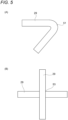
- Fig. 5 is a schematic plan view illustrating shapes of the weld beads 29.
- the shape sensor 25 disposed in parallel with the torch 23 is disposed at the starting portion of a base U of a built body WA on which the weld beads 29 are already deposited, and the shape sensor 25 and the torch 23 are moved along the built body WA. Then, the shape sensor 25 measures a height of the starting area As of the base U in the built body WA to acquire the measured height Hr (base measurement processing).
- Fig. 4 illustrates the correction ratio between the differential height ⁇ H and the travel speed in the feedback correction, and for example, the control unit 21 sets a welding condition of a correction ratio Fa (a solid line in Fig. 4 ) for the normal feedback correction.
- the control unit 21 performs the correction ratio update processing for updating the correction ratio in the welding condition. Specifically, since the starting area As is an area having a shape characteristic with a large amount of change in height, a correction ratio Fb (a dotted line in Fig. 4 ) corresponding to the shape characteristic of the starting area As is selected from the plurality of correction ratios set for each of shape characteristics stored in the database 17. Then, the correction ratio Fa in the welding condition is updated to the selected correction ratio Fb.
- This correction ratio Fb has a larger travel speed change rate with respect to the differential height ⁇ H than that of the correction ratio Fa, and therefore, by updating to this correction ratio Fb, it becomes possible to quickly change the travel speed with respect to the differential height ⁇ H in the feedback correction.
- the shape sensor 25 and the torch 23 are moved along the built body WA toward the ending side, and the weld beads 29 are deposited on the starting area As of the base U by the torch 23.
- the feedback correction is performed by the correction ratio Fb that enables the travel speed to be changed quickly with respect to the differential height ⁇ H. Therefore, the height of the weld beads 29 formed by the torch 23 can be quickly corrected with respect to shape change with a large differential height ⁇ H.
- the control unit 21 performs the correction ratio update processing for updating the correction ratio in the welding condition.
- the middle area Am is an area having a stable shape characteristic with a relatively small amount of change in height
- the control unit 21 does not select any correction ratio from the database 17, and maintains the correction ratio Fa (the solid line in Fig. 4 ) in the welding condition set in the welding condition setting processing.
- the shape sensor 25 and the torch 23 are moved along the built body WA toward the ending side, and the weld beads 29 are deposited on the middle area Am of the base U by the torch 23.
- the feedback correction is performed by the correction ratio Fa that gently changes the travel speed with respect to the differential height ⁇ H. Therefore, the height of the weld beads 29 formed by the torch 23 can be smoothly corrected with respect to shape change with a small differential height ⁇ H.
- the control unit 21 performs the correction ratio update processing for updating the correction ratio in the welding condition. Specifically, since the ending area Ae is an area having a shape characteristic with a large amount of change in height, the control unit 21 selects the correction ratio Fb (the dotted line in Fig. 4 ) corresponding to the shape characteristic of the ending area Ae from the plurality of correction ratios set for each of the shape characteristics stored in the database 17, and updates the correction ratio Fa in the welding condition to the selected correction ratio Fb.
- the correction ratio corresponding to the shape characteristic of the ending area Ae is set as the correction ratio Fb corresponding to the shape characteristic of the starting area As. Note that the correction ratios corresponding to the shape characteristics of the starting area As and the ending area Ae may be different.
- the weld beads 29 are deposited on the ending area Ae by the torch 23 that reaches the ending area Ae.
- the feedback correction is performed by the correction ratio Fb that enables the travel speed to be changed quickly with respect to the differential height ⁇ H. Therefore, the height of the weld beads 29 formed by the torch 23 can be quickly corrected with respect to shape change with a large differential height ⁇ H.
- the correction ratio of the welding condition in the feedback correction which reduces the differential height ⁇ H between the planned height Hp based on the deposition plan and the measured height Hr actually measured, is updated to the correction ratio selected from the plurality of correction ratios set and prepared in advance.
- the weld beads 29 can be stably formed by performing the feedback correction at appropriately selected correction ratios for cases of various height deviations.
- the weld beads 29 can be stably formed in an appropriate control mode according to the shape characteristic of a portion where the weld beads 29 are built.
- correction ratio is not limited to being set in advance and in plural according to the shape characteristics.
- a plurality of correction ratios may be set in advance according to positions specified based on the deposition plan.
- the specified positions include, for example, positions where variations are likely to occur locally in a frame, a filling portion within a frame, a corner of a frame, an overhang, or the like.
- the deposition height of the weld beads 29 tends to vary locally. Therefore, the bent portion 51, the crossing portion 53, or both of the two are taken as the specified positions, and the correction ratios corresponding to the specified positions are set. Then, when forming the weld beads 29, at the specified position such as the bent portion 51 or the crossing portion 53, a correction ratio corresponding to the specified position is selected, and the correction ratio in the welding condition for feedback correction is updated to the selected correction ratio. As a result, the weld beads 29 can be formed while dealing with an abrupt height variation at the specified position such as the bent portion 51 or the crossing portion 53.
- Abase profile may be obtained from the measurement result of the shape sensor 25 on a front side in a movement direction of the torch 23, and the shape characteristic of the position where the torch 23 is to be moved may be obtained in real time from this base profile and a target profile obtained from the deposition plan. Then, in the correction ratio update processing, a correction ratio corresponding to the shape characteristic obtained during building may be selected from the plurality of correction ratios set in advance, and the correction ratio in the welding condition may be updated based on the selected correction ratio.
- the weld beads 29 can be stably formed in an appropriate control mode even for an unexpected large height deviation and local unevenness, while sensing the shape of the base in real time.
- the correction ratio of the travel speed with respect to the differential height ⁇ H is used as a parameter in the feedback correction, but the parameter of the correction ratio with respect to the differential height ⁇ H is not limited to the travel speed, and may be a feeding speed of the filler material M or a heat input for generating the arc.
- a formed height of the weld beads 29 can be increased by increasing the feeding speed, and the formed height of the weld beads 29 can be reduced by reducing the feeding speed.
- the formed height of the weld beads 29 can be reduced by increasing the heat input, and the formed height of the weld beads 29 can be increased by reducing the heat input.
- the shape sensor 25 is disposed in parallel with the torch 23 as an example, but the shape sensor 25 may be disposed not in parallel with the torch 23.
- a robot that moves the shape sensor 25 may be provided separately from the welding robot 11, and this robot may measure the shape of the base on the front side in the movement direction of the torch 23 forming the weld beads 29.
- the present invention is not limited to the above-described embodiments, and the present invention intends to combine the configurations of the embodiments with each other, and is also intended to be changed and applied by those skilled in the art based on the description of the specification and a well-known technique, which are included in the scope required to be protected.
- the shape characteristic of the position where the torch is to be moved is obtained in real time from the base profile and the target profile, and the correction ratio is selected according to the shape characteristic. That is, the weld beads can be stably formed in an appropriate control mode even for an unexpected large height deviation and local unevenness, while sensing the shape of the base in real time.
Abstract
In a building step, a base measurement processing of acquiring a measured height by measuring, using a shape sensor, a height of a base at a position where a torch is to be moved when depositing weld beads; a welding condition setting processing of obtaining a planned height of the base at the position where the torch is to be moved from a deposition plan, comparing the measured height acquired in the base measurement processing and the planned height to obtain a differential height, and setting a welding condition in a feedback correction for reducing the differential height; and a correction ratio update processing of performing a selection from a plurality of correction ratios set in advance and updating a correction ratio in the welding condition based on a selected correction ratio are executed.
Description
- The present invention relates to a method for manufacturing an additively-manufactured object.
- In recent years, a need for 3D printers as a means of production increases, and research and development are carried out for practical application in the aircraft industry and the like, especially for application to metal materials. A 3D printer using a metal material melts metal powder or metal wires using a heat source such as a laser or an arc, and deposits the molten metal to build a built object.
- As a technique for building such a built object by welding, Patent Literature 1 discloses a technique of measuring a height of the built object having already been formed using a measurement unit, and feedback-controlling processing conditions when a new deposition is made at a measurement position according to a measurement result.
- Patent Literature 1:
JP6576593B1 - However, in the feedback control when building a built object by depositing beads, when a deviation in height of a base portion is locally larger than expected, normal feedback control is not able to correct the processing conditions in time and it may be difficult to stably deposit the beads. For example, at a starting portion and an ending portion of the beads, the heights of the beads in lower layers tend to deviate greatly, which is difficult to deal with by the normal feedback control.
- Accordingly, an object of the present invention is to provide a method for manufacturing an additively-manufactured object that is capable of building a good built object by constantly forming weld beads in a stable manner by appropriately performing feedback control.
- The present invention includes the following configuration.
- A method for manufacturing an additively-manufactured object, in which weld beads obtained by melting and solidifying a filler material is deposited with a torch while moving the torch to build a built object, the method including:
- a building step of moving the torch to deposit the weld beads based on a deposition plan that defines a shape of the weld beads obtained from a target shape of the built object and a trajectory of the torch for forming the weld beads, in which
- in the building step,
- a base measurement processing of acquiring a measured height by measuring, using a shape sensor, a height of a base at a position where the torch is to be moved when depositing the weld beads,
- a welding condition setting processing of obtaining a planned height of the base at the position where the torch is to be moved from the deposition plan, comparing the measured height acquired in the base measurement processing and the planned height to obtain a differential height, and setting a welding condition in a feedback correction for reducing the differential height, and
- a correction ratio update processing of performing a selection from a plurality of correction ratios set in advance and updating a correction ratio in the welding condition based on a selected correction ratio
- are executed.
- The present invention is capable of building a good built object by constantly forming weld beads in a stable manner by appropriately performing feedback control.
-
- [
Fig. 1] Fig. 1 is a schematic configuration diagram of a manufacturing system for manufacturing an additively-manufactured object by a manufacturing method according to an embodiment of the present invention. - [
Fig. 2] Fig. 2 is a diagram illustrating wall portions formed by depositing weld beads, in which (A) and (B) are both schematic side views. - [
Fig. 3] Fig. 3 is a diagram illustrating a building step of building a wall portion by depositing weld beads, in which (A) to (E) are all schematic side views of the wall portion. - [
Fig. 4] Fig. 4 is a graph illustrating correction ratios in a welding condition. - [
Fig. 5] Fig. 5 is a diagram illustrating shapes of weld beads, in which (A) is a schematic plan view of a weld bead including a bent portion, and (B) is a schematic plan view of a weld bead including a crossing portion. - Hereinafter, an embodiment of the present invention will be described in detail with reference to the drawings.
-
Fig. 1 is a schematic configuration diagram of amanufacturing system 100 for manufacturing an additively-manufactured object by a manufacturing method according to the embodiment of the present invention. - The
manufacturing system 100 for an additively-manufactured object having the present configuration includes awelding robot 11, arobot controller 13, a fillermaterial supply unit 15, awelding power source 19, and acontrol unit 21. - The
welding robot 11 is an articulated robot, and includes a tip shaft on which atorch 23 is supported. Position and posture of thetorch 23 can be freely set three-dimensionally within a range of degrees of freedom of a robot arm. Thetorch 23 holds the filler material (welding wire) M continuously supplied from the fillermaterial supply unit 15 in a state of protruding from a tip of the torch. Ashape sensor 25 is provided on the tip shaft of thewelding robot 11 together with thetorch 23. - The
torch 23 includes a shield nozzle (not shown), and shield gas is supplied from the shield nozzle to a weld part. An arc welding method may be a consumable electrode type such as shielded metal arc welding and carbon dioxide gas arc welding, or a non-consumable electrode type such as TIG welding and plasma arc welding, and is appropriately selected depending on an additively-manufactured object to be manufactured. - For example, in the case of the consumable electrode type, a contact tip is disposed inside the shield nozzle, and the filler material M to which a melting current is supplied is held on the contact tip. While holding the filler material M, the
torch 23 generates an arc from a tip end of the filler material M in a shield gas atmosphere. The filler material M is fed to thetorch 23 by a delivery mechanism (not shown) mounted on the robot arm or the like. Then, when the continuously fed filler material M is melted and solidified while thetorch 23 is moved,weld beads 29, which are melted and solidified bodies of the filler material M, are formed on abase plate 27. - The
base plate 27 is made of a metal plate such as a steel plate, and is basically larger than a bottom surface (lowermost layer surface) of an additively-manufactured object W. Thebase plate 27 is not limited to a plate-like shape base, and may be of other shapes such as a block body shape and a rod-like shape. - A heat source for melting the filler material M is not limited to the above-described arc. A heat source using another method such as a heating method using an arc and a laser together, a heating method using plasma, or a heating method using an electron beam or a laser may be used. In the case of heating by an electron beam or a laser, a heating amount may be controlled more finely to keep each weld bead in a more proper state, thereby contributing to further improvement in quality of the additively-manufactured object.
- Any commercially available welding wire can be used as the filler material M. For example, wires defined in MAG welding solid wires and MIG welding solid wires for mild steel, high tensile steel, and cryogenic steel (JIS Z 3312), arc welding flux-cored wires for mild steel, high tensile steel, and cryogenic steel (JIS Z 3313) and the like can be used.
- An active metal such as titanium can also be used as the filler material M. In this case, it is necessary to put the weld part into the shield gas atmosphere in order to avoid oxidation and nitridation due to reaction with the atmosphere during welding.
- The
shape sensor 25 is disposed in parallel with thetorch 23 and is moved together with thetorch 23. Theshape sensor 25 is a sensor for measuring a shape of a portion serving as a base when forming weld beads B. As theshape sensor 25, for example, a laser sensor that acquires reflected light of emitted laser light as height data is used. Note that a three-dimensional shape measuring camera may be used as theshape sensor 25. - The
robot controller 13 receives an instruction from thecontrol unit 21 to drive each portion of thewelding robot 11 and controls an output of thewelding power source 19 as necessary. - The
control unit 21 is implemented by a computer device including a CPU, a memory, a storage, and the like, and executes a drive program prepared in advance or a drive program created under desired conditions to drive each portion of thewelding robot 11 and the like. As a result, the additively-manufactured object W having a multi-layer structure is built by moving thetorch 23 according to the drive program and depositing theweld beads 29 in multiple layers on thebase plate 27 based on a created deposition plan. Adatabase 17 is also connected to thecontrol unit 21. In thisdatabase 17, data of a plurality of correction ratios in a welding condition during feedback correction is stored in advance. - Next, a case where the additively-manufactured object W is manufactured by the
manufacturing system 100 will be described. -
Fig. 2 is a schematic side view of an additively-manufactured object in which thelinear weld beads 29 are deposited on thebase plate 27 to build a wall portion Wo.Fig. 3 is a step diagram illustrating a building step of building the wall portion Wo by depositing theweld beads 29. - As illustrated in (A) of
Fig. 2 , when building the wall portion Wo, one end (a left end in (A) ofFig. 2 ) side is used as a starting, and thetorch 23 is moved from this starting to start forming theweld beads 29, and thetorch 23 is moved to an ending on the other end (a right end in (A) ofFig. 2 ) side to complete the formation of theweld beads 29. Then, the formation of thelinear weld beads 29 is repeated to build the wall portion Wo in which the plurality oflinear weld beads 29 are deposited. In this case, thecontrol unit 21 measures the shape of the base with theshape sensor 25 disposed in parallel with thetorch 23, and performs the feedback correction for correcting the welding condition based on a measurement result. - As illustrated in (B) of
Fig. 2 , when theweld beads 29 are formed by moving thetorch 23 from the starting to the ending, in a middle portion between a starting portion and an ending portion of theweld beads 29, the formation of theweld beads 29 by thetorch 23 is stabilized. Therefore, in a middle area Am, it is possible to build into a shape with less unevenness along a target shape based on the deposition plan. As a result, the middle area Am, which can be formed with this stable thickness, can be dealt with by normal feedback correction. - On the other hand, in a starting area As and an ending area Ae, a thickness of the formed
weld beads 29 tends to be unstable. Specifically, theweld beads 29 tend to thicken and swell in the starting area As, and theweld beads 29 tend to thin and droop in the ending area Ae. Therefore, in the starting area As and the ending area Ae where the thickness is unstable, the normal feedback correction may not be able to make correction in time. - In this case, in order to deal with the starting area As and the ending area Ae, the correction ratio of the welding condition in the feedback correction may be increased, but in the middle area Am where the
weld beads 29 can be stably formed, abrupt correction rather causes large unevenness. - For this reason, in the manufacturing method according to the present embodiment, the following feedback correction is performed in the building step of depositing the
weld beads 29. - The
shape sensor 25 measures a height of the base at a position where thetorch 23 is to be moved when theweld beads 29 are deposited. Then, a measured height Hr, which is the height of the base measured by theshape sensor 25, is obtained. - A planned height Hp of the base at the position where the
torch 23 is to be moved is obtained from the deposition plan, and a differential height ΔH (ΔH = Hr - Hp) is obtained by comparing the measured height Hr acquired in the base measurement processing and the planned height Hp, and the welding condition is set so as to reduce the differential height ΔH. - Selection from the plurality of correction ratios set in advance is performed according to a shape characteristic of the position where the
torch 23 is to be moved. The plurality of correction ratios is pre-determined by, for example, experiments or the like in order to stably form theweld beads 29 with respect to various shape characteristics, and are stored in thedatabase 17. Then, based on a selected correction ratio, a correction ratio in the welding condition (for example, a ratio of increase or decrease in a travel speed with respect to the differential height ΔH) is updated. For example, in portions where the thickness is unstable, such as the starting area As and the ending area Ae, when building the wall portion Wo, correction ratios corresponding to the shape characteristics of these portions are selected and retrieved from thedatabase 17, and the correction ratio of the welding condition is updated to the selected correction ratios. Note that in this correction ratio update processing, when the position where thetorch 23 is to be moved has a shape characteristic that does not require updating the correction ratio of the welding condition, the correction ratio in the welding condition set in the welding condition setting processing is maintained without selecting any correction ratio. For example, in the portion where the thickness is stable, such as the middle area Am when building the wall portion Wo, the correction ratio in the welding condition set in the welding condition setting processing is maintained. - When updating the above-described correction ratio, a maintenance period (correction interval Δt) for maintaining a state in which the correction ratio is changed for a predetermined period may also be set. The correction interval Δt may be set in terms of time or length along a path. A unique correction interval Δt may be set only for a specific correction ratio.
- When the correction interval Δt is not set, correction control is performed in a short period of time in accordance with local changes in height of the existing weld beads (height of base), and depending on a condition, the correction control may be a transient reaction. In that case, a height of a newly formed weld bead may be greater than local unevenness of the base.
- Therefore, by reducing sensitivity of the correction control by setting the correction interval Δt, it is possible to mitigate the reaction so as to form a gently uneven base shape without causing a local steep height change. In this way, it becomes relatively easy to correct a height of a layer (an upper layer) to be formed next.
- Next, an example of the feedback correction in the building step when building the wall portion Wo will be described.
-
Fig. 4 is a graph illustrating correction ratios in a welding condition.Fig. 5 is a schematic plan view illustrating shapes of theweld beads 29. - As illustrated in (A) of
Fig. 3 , theshape sensor 25 disposed in parallel with thetorch 23 is disposed at the starting portion of a base U of a built body WA on which theweld beads 29 are already deposited, and theshape sensor 25 and thetorch 23 are moved along the built body WA. Then, theshape sensor 25 measures a height of the starting area As of the base U in the built body WA to acquire the measured height Hr (base measurement processing). - The
control unit 21 obtains the planned height Hp of the base U from the deposition plan, and compares the measured height Hr acquired by theshape sensor 25 with the planned height Hp. Then, the measured height Hr, the planned height Hp, and the differential height ΔH (ΔH = Hr - Hp) are obtained, and the welding condition is set so as to reduce the differential height ΔH (welding condition setting processing). - Here,
Fig. 4 illustrates the correction ratio between the differential height ΔH and the travel speed in the feedback correction, and for example, thecontrol unit 21 sets a welding condition of a correction ratio Fa (a solid line inFig. 4 ) for the normal feedback correction. - Next, the
control unit 21 performs the correction ratio update processing for updating the correction ratio in the welding condition. Specifically, since the starting area As is an area having a shape characteristic with a large amount of change in height, a correction ratio Fb (a dotted line inFig. 4 ) corresponding to the shape characteristic of the starting area As is selected from the plurality of correction ratios set for each of shape characteristics stored in thedatabase 17. Then, the correction ratio Fa in the welding condition is updated to the selected correction ratio Fb. This correction ratio Fb has a larger travel speed change rate with respect to the differential height ΔH than that of the correction ratio Fa, and therefore, by updating to this correction ratio Fb, it becomes possible to quickly change the travel speed with respect to the differential height ΔH in the feedback correction. - As illustrated in (B) of
Fig. 3 , theshape sensor 25 and thetorch 23 are moved along the built body WA toward the ending side, and theweld beads 29 are deposited on the starting area As of the base U by thetorch 23. In this case, the feedback correction is performed by the correction ratio Fb that enables the travel speed to be changed quickly with respect to the differential height ΔH. Therefore, the height of theweld beads 29 formed by thetorch 23 can be quickly corrected with respect to shape change with a large differential height ΔH. - When the
torch 23 forms theweld beads 29 in the starting area As, theshape sensor 25 disposed in parallel with thetorch 23 continues to measure a height of the middle area Am of the base U (base measurement processing). Then, the measured height Hr and the planned height Hp are compared to obtain the differential height ΔH (ΔH = Hr - Hp), and for example, the welding condition of the correction ratio Fa (the solid line inFig. 4 ) for the normal feedback correction is set so as to reduce the differential height ΔH (welding condition setting processing). - Next, the
control unit 21 performs the correction ratio update processing for updating the correction ratio in the welding condition. Here, since the middle area Am is an area having a stable shape characteristic with a relatively small amount of change in height, in the correction ratio update processing, thecontrol unit 21 does not select any correction ratio from thedatabase 17, and maintains the correction ratio Fa (the solid line inFig. 4 ) in the welding condition set in the welding condition setting processing. - As illustrated in (C) of
Fig. 3 , theshape sensor 25 and thetorch 23 are moved along the built body WA toward the ending side, and theweld beads 29 are deposited on the middle area Am of the base U by thetorch 23. In this case, the feedback correction is performed by the correction ratio Fa that gently changes the travel speed with respect to the differential height ΔH. Therefore, the height of theweld beads 29 formed by thetorch 23 can be smoothly corrected with respect to shape change with a small differential height ΔH. - As illustrated in (D) of
Fig. 3 , when theshape sensor 25 reaches the ending area Ae of the base U of the built body WA, the height of the ending area Ae is measured by theshape sensor 25 to acquire the measured height Hr (base measurement processing). Then, the measured height Hr and the planned height Hp of the base U from the deposition plan are compared to obtain the differential height ΔH (ΔH=Hr-Hp), and the welding condition of the correction ratio Fa (the solid line inFig. 4 ) is set so as to reduce the differential height ΔH (welding condition setting processing). - Next, the
control unit 21 performs the correction ratio update processing for updating the correction ratio in the welding condition. Specifically, since the ending area Ae is an area having a shape characteristic with a large amount of change in height, thecontrol unit 21 selects the correction ratio Fb (the dotted line inFig. 4 ) corresponding to the shape characteristic of the ending area Ae from the plurality of correction ratios set for each of the shape characteristics stored in thedatabase 17, and updates the correction ratio Fa in the welding condition to the selected correction ratio Fb. Here, the correction ratio corresponding to the shape characteristic of the ending area Ae is set as the correction ratio Fb corresponding to the shape characteristic of the starting area As. Note that the correction ratios corresponding to the shape characteristics of the starting area As and the ending area Ae may be different. - As illustrated in (E) of
Fig. 3 , theweld beads 29 are deposited on the ending area Ae by thetorch 23 that reaches the ending area Ae. In this case, the feedback correction is performed by the correction ratio Fb that enables the travel speed to be changed quickly with respect to the differential height ΔH. Therefore, the height of theweld beads 29 formed by thetorch 23 can be quickly corrected with respect to shape change with a large differential height ΔH. - As described above, according to the method for manufacturing an additively-manufactured object according to the present embodiment, the correction ratio of the welding condition in the feedback correction, which reduces the differential height ΔH between the planned height Hp based on the deposition plan and the measured height Hr actually measured, is updated to the correction ratio selected from the plurality of correction ratios set and prepared in advance. In this way, the
weld beads 29 can be stably formed by performing the feedback correction at appropriately selected correction ratios for cases of various height deviations. - For example, by setting a small correction ratio for a position with an average and moderate height deviation and setting a large correction ratio for a local and large height deviation, the
weld beads 29 can be stably formed in an appropriate control mode according to the shape characteristic of a portion where theweld beads 29 are built. - Note that the correction ratio is not limited to being set in advance and in plural according to the shape characteristics. A plurality of correction ratios may be set in advance according to positions specified based on the deposition plan. The specified positions include, for example, positions where variations are likely to occur locally in a frame, a filling portion within a frame, a corner of a frame, an overhang, or the like.
- For example, at a
bent portion 51 when theweld beads 29 are bent and deposited as illustrated in (A) ofFig. 5 , at a crossingportion 53 when theweld beads 29 are crossed in a cross shape and deposited as illustrated in (B) ofFig. 5 , or the like, the deposition height of theweld beads 29 tends to vary locally. Therefore, thebent portion 51, the crossingportion 53, or both of the two are taken as the specified positions, and the correction ratios corresponding to the specified positions are set. Then, when forming theweld beads 29, at the specified position such as thebent portion 51 or the crossingportion 53, a correction ratio corresponding to the specified position is selected, and the correction ratio in the welding condition for feedback correction is updated to the selected correction ratio. As a result, theweld beads 29 can be formed while dealing with an abrupt height variation at the specified position such as thebent portion 51 or the crossingportion 53. - Abase profile may be obtained from the measurement result of the
shape sensor 25 on a front side in a movement direction of thetorch 23, and the shape characteristic of the position where thetorch 23 is to be moved may be obtained in real time from this base profile and a target profile obtained from the deposition plan. Then, in the correction ratio update processing, a correction ratio corresponding to the shape characteristic obtained during building may be selected from the plurality of correction ratios set in advance, and the correction ratio in the welding condition may be updated based on the selected correction ratio. - In this way, when forming the
weld beads 29, theweld beads 29 can be stably formed in an appropriate control mode even for an unexpected large height deviation and local unevenness, while sensing the shape of the base in real time. - Note that in the above embodiment, the correction ratio of the travel speed with respect to the differential height ΔH is used as a parameter in the feedback correction, but the parameter of the correction ratio with respect to the differential height ΔH is not limited to the travel speed, and may be a feeding speed of the filler material M or a heat input for generating the arc.
- For example, when the feeding speed of the filler material M is used as the parameter, a formed height of the
weld beads 29 can be increased by increasing the feeding speed, and the formed height of theweld beads 29 can be reduced by reducing the feeding speed. When the heat input is used as the parameter, the formed height of theweld beads 29 can be reduced by increasing the heat input, and the formed height of theweld beads 29 can be increased by reducing the heat input. - In the above embodiment, the
shape sensor 25 is disposed in parallel with thetorch 23 as an example, but theshape sensor 25 may be disposed not in parallel with thetorch 23. For example, a robot that moves theshape sensor 25 may be provided separately from thewelding robot 11, and this robot may measure the shape of the base on the front side in the movement direction of thetorch 23 forming theweld beads 29. - Therefore, the present invention is not limited to the above-described embodiments, and the present invention intends to combine the configurations of the embodiments with each other, and is also intended to be changed and applied by those skilled in the art based on the description of the specification and a well-known technique, which are included in the scope required to be protected.
- As described above, the present description discloses the following matters.
- (1) A method for manufacturing an additively-manufactured object, in which weld beads obtained by melting and solidifying a filler material is deposited with a torch while moving the torch to build a built object, the method including:
- a building step of moving the torch to deposit the weld beads based on a deposition plan that defines a shape of the weld beads obtained from a target shape of the built object and a trajectory of the torch for forming the weld beads, in which
- in the building step,
- a base measurement processing of acquiring a measured height by measuring, using a shape sensor, a height of a base at a position where the torch is to be moved when depositing the weld beads,
- a welding condition setting processing of obtaining a planned height of the base at the position where the torch is to be moved from the deposition plan, comparing the measured height acquired in the base measurement processing and the planned height to obtain a differential height, and setting a welding condition in a feedback correction for reducing the differential height, and
- a correction ratio update processing of performing a selection from a plurality of correction ratios set in advance and updating a correction ratio in the welding condition based on a selected correction ratio
- are executed.
- According to the method for manufacturing an additively-manufactured object, the correction ratio of the welding condition in the feedback correction, which reduces the differential height between the planned height based on the deposition plan and the measured height actually measured, is updated to the correction ratio selected from the plurality of correction ratios set and prepared in advance. In this way, the weld beads can be stably formed by performing the feedback correction at appropriately selected correction ratios for cases of various height deviations.
- (2) The method for manufacturing an additively-manufactured object according to (1), in which the plurality of correction ratios is set according to a shape characteristic of a position where the weld beads are deposited.
According to the method for manufacturing an additively-manufactured object, for example, by setting a small correction ratio for a position with an average and moderate height deviation and setting a large correction ratio for a local and large height deviation, the weld beads can be stably formed in an appropriate control mode according to the shape characteristic of a portion where the weld beads are built. - (3) The method for manufacturing an additively-manufactured object according to (2), in which the plurality of correction ratios is set in advance according to a shape characteristic of a position specified based on the deposition plan.
According to the method for manufacturing an additively-manufactured object, the weld beads can be stably formed in an appropriate control mode according to a position that can be recognized in advance based on the deposition plan. - (4) The method for manufacturing an additively-manufactured object according to (2), in which in the correction ratio update processing, a base profile is obtained from a measurement result of the shape sensor, a shape characteristic of the position where the torch is to be moved is obtained from the base profile and a target profile obtained from the deposition plan, the selection from the plurality of correction ratios set in advance is performed according to the shape characteristic, and the correction ratio in the welding condition is updated based on the selected correction ratio.
- According to the method for manufacturing an additively-manufactured object, the shape characteristic of the position where the torch is to be moved is obtained in real time from the base profile and the target profile, and the correction ratio is selected according to the shape characteristic. That is, the weld beads can be stably formed in an appropriate control mode even for an unexpected large height deviation and local unevenness, while sensing the shape of the base in real time.
- The present application is based on a
Japanese Patent Application (Patent Application No. 2021-000993) filed on January 6, 2021 -
- 23 torch
- 29 weld bead
- 25 shape sensor
- Fa, Fb correction ratio
- ΔH differential height
- M filler material
- U base
- W additively-manufactured object
Claims (6)
- A method for manufacturing an additively-manufactured object, wherein weld beads obtained by melting and solidifying a filler material is deposited with a torch while moving the torch to build a built object, the method comprising:a building step of moving the torch to deposit the weld beads based on a deposition plan that defines a shape of the weld beads obtained from a target shape of the built object and a trajectory of the torch for forming the weld beads, whereinin the building step,a base measurement processing of acquiring a measured height by measuring, using a shape sensor, a height of a base at a position where the torch is to be moved when depositing the weld beads,a welding condition setting processing of obtaining a planned height of the base at the position where the torch is to be moved from the deposition plan, comparing the measured height acquired in the base measurement processing and the planned height to obtain a differential height, and setting a welding condition in a feedback correction for reducing the differential height, anda correction ratio update processing of performing a selection from a plurality of correction ratios set in advance and updating a correction ratio in the welding condition based on a selected correction ratioare executed.
- The method for manufacturing an additively-manufactured object according to claim 1, wherein
the plurality of correction ratios is set according to a shape characteristic of a position where the weld beads are deposited. - The method for manufacturing an additively-manufactured object according to claim 1, wherein
a correction interval is provided for maintaining a state in which the correction ratio is changed for a predetermined period. - The method for manufacturing an additively-manufactured object according to claim 2, wherein
a correction interval is provided for maintaining a state in which the correction ratio is changed for a predetermined period. - The method for manufacturing an additively-manufactured object according to any one of claims 2 to 4, wherein
the plurality of correction ratios is set in advance according to a shape characteristic of a position specified based on the deposition plan. - The method for manufacturing an additively-manufactured object according to any one of claims 2 to 4, wherein
in the correction ratio update processing, a base profile is obtained from a measurement result of the shape sensor, a shape characteristic of the position where the torch is to be moved is obtained from the base profile and a target profile obtained from the deposition plan, the selection from the plurality of correction ratios set in advance is performed according to the shape characteristic, and the correction ratio in the welding condition is updated based on the selected correction ratio.
Applications Claiming Priority (2)
| Application Number | Priority Date | Filing Date | Title |
|---|---|---|---|
| JP2021000993A JP2022106172A (en) | 2021-01-06 | 2021-01-06 | Laminate molded article manufacturing method |
| PCT/JP2021/046395 WO2022149426A1 (en) | 2021-01-06 | 2021-12-15 | Method for fabricating additively manufactured object |
Publications (1)
| Publication Number | Publication Date |
|---|---|
| EP4245450A1 true EP4245450A1 (en) | 2023-09-20 |
Family
ID=82357265
Family Applications (1)
| Application Number | Title | Priority Date | Filing Date |
|---|---|---|---|
| EP21917647.6A Pending EP4245450A1 (en) | 2021-01-06 | 2021-12-15 | Method for fabricating additively manufactured object |
Country Status (5)
| Country | Link |
|---|---|
| US (1) | US20240051052A1 (en) |
| EP (1) | EP4245450A1 (en) |
| JP (1) | JP2022106172A (en) |
| CN (1) | CN116685430A (en) |
| WO (1) | WO2022149426A1 (en) |
Family Cites Families (2)
| Publication number | Priority date | Publication date | Assignee | Title |
|---|---|---|---|---|
| WO2020095454A1 (en) | 2018-11-09 | 2020-05-14 | 三菱電機株式会社 | Layering/molding device |
| JP6765569B1 (en) * | 2019-08-07 | 2020-10-07 | 三菱電機株式会社 | Laminated modeling equipment, laminated modeling method, and laminated modeling program |
-
2021
- 2021-01-06 JP JP2021000993A patent/JP2022106172A/en active Pending
- 2021-12-15 US US18/258,170 patent/US20240051052A1/en active Pending
- 2021-12-15 EP EP21917647.6A patent/EP4245450A1/en active Pending
- 2021-12-15 WO PCT/JP2021/046395 patent/WO2022149426A1/en active Application Filing
- 2021-12-15 CN CN202180087883.2A patent/CN116685430A/en active Pending
Also Published As
| Publication number | Publication date |
|---|---|
| JP2022106172A (en) | 2022-07-19 |
| WO2022149426A1 (en) | 2022-07-14 |
| CN116685430A (en) | 2023-09-01 |
| US20240051052A1 (en) | 2024-02-15 |
Similar Documents
| Publication | Publication Date | Title |
|---|---|---|
| CN111417485B (en) | Method and apparatus for manufacturing shaped object | |
| EP3693118B1 (en) | Hybrid additive manufacturing system using laser and arc welding | |
| EP3711887A1 (en) | Method and apparatus for manufacturing layered model | |
| US20230191690A1 (en) | Laminate molding method | |
| US20190388968A1 (en) | Flexible hybrid additive manufacturing for specified alloy creation | |
| US20220226943A1 (en) | Manufacturing method for additive manufactured article and additive manufactured article | |
| EP3711889A1 (en) | Method for producing molded article, production device, and molded article | |
| JP6810018B2 (en) | Manufacturing method of laminated model | |
| EP4245450A1 (en) | Method for fabricating additively manufactured object | |
| EP3871820B1 (en) | Method for manufacturing laminated molding | |
| US11292071B2 (en) | Method for producing molded article, production device, and molded article | |
| JP6859471B1 (en) | Manufacturing method of laminated model | |
| US20230286074A1 (en) | System for manufacturing additively-manufactured object, method for manufacturing additively-manufactured object, and non-transitory computer readable medium storing a program for manufacturing additively-manufactured object | |
| CN115867407A (en) | Machine learning device, laminate modeling system, machine learning method for welding conditions, adjustment method for welding conditions, and program | |
| JP2022039535A (en) | Manufacturing method of molded article and molded article | |
| EP4177002A1 (en) | Method for manufacturing multi-layer molded article | |
| EP4219058A1 (en) | Stacking plan creating method | |
| EP4306321A1 (en) | Additive manufacturing method, additive manufacturing apparatus, and program for manufacturing additively manufactured article | |
| US20230294191A1 (en) | Molded object manufacturing method and molded object | |
| JP2022117176A (en) | Method for manufacturing laminated molding and display device | |
| JP2024013526A (en) | Control information modification method, control information modification device and program |
Legal Events
| Date | Code | Title | Description |
|---|---|---|---|
| STAA | Information on the status of an ep patent application or granted ep patent |
Free format text: STATUS: THE INTERNATIONAL PUBLICATION HAS BEEN MADE |
|
| PUAI | Public reference made under article 153(3) epc to a published international application that has entered the european phase |
Free format text: ORIGINAL CODE: 0009012 |
|
| STAA | Information on the status of an ep patent application or granted ep patent |
Free format text: STATUS: REQUEST FOR EXAMINATION WAS MADE |
|
| 17P | Request for examination filed |
Effective date: 20230616 |
|
| AK | Designated contracting states |
Kind code of ref document: A1 Designated state(s): AL AT BE BG CH CY CZ DE DK EE ES FI FR GB GR HR HU IE IS IT LI LT LU LV MC MK MT NL NO PL PT RO RS SE SI SK SM TR |
|
| RIN1 | Information on inventor provided before grant (corrected) |
Inventor name: YOSHIKAWA, AKINORI |
|
| DAV | Request for validation of the european patent (deleted) | ||
| DAX | Request for extension of the european patent (deleted) |