EP4245187A2 - Pull-out guide for a movable furniture part - Google Patents
Pull-out guide for a movable furniture part Download PDFInfo
- Publication number
- EP4245187A2 EP4245187A2 EP23190508.4A EP23190508A EP4245187A2 EP 4245187 A2 EP4245187 A2 EP 4245187A2 EP 23190508 A EP23190508 A EP 23190508A EP 4245187 A2 EP4245187 A2 EP 4245187A2
- Authority
- EP
- European Patent Office
- Prior art keywords
- depth adjustment
- pull
- out guide
- rail
- carrier
- Prior art date
- Legal status (The legal status is an assumption and is not a legal conclusion. Google has not performed a legal analysis and makes no representation as to the accuracy of the status listed.)
- Pending
Links
- 230000033001 locomotion Effects 0.000 claims abstract description 27
- 230000005540 biological transmission Effects 0.000 claims description 10
- 230000007246 mechanism Effects 0.000 claims description 4
- 238000006073 displacement reaction Methods 0.000 description 3
- 238000003825 pressing Methods 0.000 description 3
- 238000001746 injection moulding Methods 0.000 description 2
- 238000004519 manufacturing process Methods 0.000 description 2
- 230000008859 change Effects 0.000 description 1
- 238000006243 chemical reaction Methods 0.000 description 1
- 238000007906 compression Methods 0.000 description 1
- 230000001419 dependent effect Effects 0.000 description 1
- 230000000694 effects Effects 0.000 description 1
- 238000003780 insertion Methods 0.000 description 1
- 230000037431 insertion Effects 0.000 description 1
- 239000002184 metal Substances 0.000 description 1
- 238000003860 storage Methods 0.000 description 1
- 230000007306 turnover Effects 0.000 description 1
Images


Classifications
-
- A—HUMAN NECESSITIES
- A47—FURNITURE; DOMESTIC ARTICLES OR APPLIANCES; COFFEE MILLS; SPICE MILLS; SUCTION CLEANERS IN GENERAL
- A47B—TABLES; DESKS; OFFICE FURNITURE; CABINETS; DRAWERS; GENERAL DETAILS OF FURNITURE
- A47B88/00—Drawers for tables, cabinets or like furniture; Guides for drawers
- A47B88/40—Sliding drawers; Slides or guides therefor
- A47B88/407—Adjustably or detachably mounted drawers
-
- A—HUMAN NECESSITIES
- A47—FURNITURE; DOMESTIC ARTICLES OR APPLIANCES; COFFEE MILLS; SPICE MILLS; SUCTION CLEANERS IN GENERAL
- A47B—TABLES; DESKS; OFFICE FURNITURE; CABINETS; DRAWERS; GENERAL DETAILS OF FURNITURE
- A47B88/00—Drawers for tables, cabinets or like furniture; Guides for drawers
- A47B88/40—Sliding drawers; Slides or guides therefor
- A47B88/453—Actuated drawers
- A47B88/46—Actuated drawers operated by mechanically-stored energy, e.g. by springs
- A47B88/463—Actuated drawers operated by mechanically-stored energy, e.g. by springs self-opening
-
- A—HUMAN NECESSITIES
- A47—FURNITURE; DOMESTIC ARTICLES OR APPLIANCES; COFFEE MILLS; SPICE MILLS; SUCTION CLEANERS IN GENERAL
- A47B—TABLES; DESKS; OFFICE FURNITURE; CABINETS; DRAWERS; GENERAL DETAILS OF FURNITURE
- A47B88/00—Drawers for tables, cabinets or like furniture; Guides for drawers
- A47B88/40—Sliding drawers; Slides or guides therefor
- A47B88/483—Sliding drawers; Slides or guides therefor with single extensible guides or parts
-
- A—HUMAN NECESSITIES
- A47—FURNITURE; DOMESTIC ARTICLES OR APPLIANCES; COFFEE MILLS; SPICE MILLS; SUCTION CLEANERS IN GENERAL
- A47B—TABLES; DESKS; OFFICE FURNITURE; CABINETS; DRAWERS; GENERAL DETAILS OF FURNITURE
- A47B2210/00—General construction of drawers, guides and guide devices
- A47B2210/0002—Guide construction for drawers
- A47B2210/0018—Buffers, stop blocks or latches for single drawer slides
-
- A—HUMAN NECESSITIES
- A47—FURNITURE; DOMESTIC ARTICLES OR APPLIANCES; COFFEE MILLS; SPICE MILLS; SUCTION CLEANERS IN GENERAL
- A47B—TABLES; DESKS; OFFICE FURNITURE; CABINETS; DRAWERS; GENERAL DETAILS OF FURNITURE
- A47B2210/00—General construction of drawers, guides and guide devices
- A47B2210/0002—Guide construction for drawers
- A47B2210/0051—Guide position
- A47B2210/0059—Guide located at the side of the drawer
-
- A—HUMAN NECESSITIES
- A47—FURNITURE; DOMESTIC ARTICLES OR APPLIANCES; COFFEE MILLS; SPICE MILLS; SUCTION CLEANERS IN GENERAL
- A47B—TABLES; DESKS; OFFICE FURNITURE; CABINETS; DRAWERS; GENERAL DETAILS OF FURNITURE
- A47B2220/00—General furniture construction, e.g. fittings
- A47B2220/0022—Slides
-
- A—HUMAN NECESSITIES
- A47—FURNITURE; DOMESTIC ARTICLES OR APPLIANCES; COFFEE MILLS; SPICE MILLS; SUCTION CLEANERS IN GENERAL
- A47B—TABLES; DESKS; OFFICE FURNITURE; CABINETS; DRAWERS; GENERAL DETAILS OF FURNITURE
- A47B88/00—Drawers for tables, cabinets or like furniture; Guides for drawers
- A47B88/40—Sliding drawers; Slides or guides therefor
- A47B88/473—Braking devices, e.g. linear or rotational dampers or friction brakes; Buffers; End stops
- A47B88/477—Buffers; End stops
Definitions
- the present invention relates to a pull-out guide for a furniture part that can be moved relative to a furniture body, in particular for a drawer, with a body rail to be connected to the furniture body, a drawer rail movably mounted on the body rail, which can be connected to the movable furniture part and has a longitudinal axis, wherein the drawer rail is movable along the longitudinal axis in the opening and closing direction of the movable furniture part, a drive device for moving the drawer rail and the movable furniture part connectable thereto at least in a partial area of the movement path between a closed position and an open position and a depth adjustment device for adjusting the closed position of the drawer rail relatively to the body rail, wherein the depth adjustment device has a carrier, a stop element movable relative to the carrier along the longitudinal axis and a depth adjustment wheel rotatably mounted on the carrier about an axis of rotation for moving the stop element along the longitudinal axis.
- the present invention relates to a piece of furniture with a furniture body, a
- the AT 512 748 B1 shows an adjusting device for adjusting a position of a drawer relative to a drawer pull-out guide with a stop that can be moved by an adjusting wheel to rest on the drawer pull-out guide. This means that it is not the relative position between the drawer rail and the cabinet rail that is set in the closed position, but rather the relative position of the drawer to the drawer rail. No ejection device is described.
- the adjustment wheel rotates about an axis of rotation which is aligned transversely to the longitudinal axis of the shutter rail.
- the adjusting wheel can be rotated about an axis of rotation which is aligned parallel to the longitudinal axis of the drawer rail.
- the ejection device described has a force-applied drive element.
- the position of this drive element relative to a driver can be adjusted using a knurled nut can be adjusted to adjust the closing position of the movable furniture part.
- the ejection device including the drive element and knurled nut is either completely fixed to the furniture body or fixed to the movable furniture part.
- An example is shown with ejectors attached to the bottom of the drawer on both sides.
- the disadvantage of the variant fixed to the furniture body is, among other things, that the knurled nut in the depth of the furniture body is very difficult or difficult to reach by hand.
- the disadvantage of the variant fixed to the furniture body is, among other things, that the ejection device takes up a relatively large amount of space on the drawer and that the entire furniture fitting (pull-out guide including ejection device) therefore has to be relatively wide.
- the ejection device in order to be able to adjust the gap between the front panel and the furniture body, an adjustment mechanism for the ejection stop is provided on the carriage, which has an adjustment path. By turning the nut, the ejection stop can be moved in the closing or opening direction. The adjustment of the panel gap can be carried out either with the thrust element open or closed, with better access to the nut on the underside of the drawer when the thrust element is open.
- the disadvantage is that the entire furniture fitting takes up a lot of space and is relatively wide.
- a similar embodiment variant is shown in the DE 20 2015 104 436 U1 shown embodiment, in which the ejector unit and the adjustment arrangement attached to this ejector unit are attached to the underside of a drawer.
- the device can also be attached to guide means of the furniture part and/or to the furniture body.
- the adjustment arrangement it is also stated that this can be designed independently of other elements, such as an ejector or a trigger of the energy accumulator of the device on the furniture and/or on the movable furniture part and/or on guide means of the furniture part. It is not stated that the adjustment arrangement is designed or arranged independently of the entire ejector unit.
- the EP 1 996 046 B1 shows a device for influencing the movement of furniture parts that can move towards one another.
- Adjustment means are provided for adjusting the position of a positioning element on the movement rail, on which a pull-pressure element acts to apply the drive effect to the furniture part.
- the adjusting element is fixed to an attachment element, this attachment element in turn being attached to the drawer rail.
- the displacement rod of the pull-compression element is attached to the base rail part (corresponds to the body rail) via a guide profile.
- the adjusting element is therefore assigned to the drawer rail, while the pull-push element including the displacement rod (corresponds to the ejection device) is assigned to the body rail. What is complicated with this state of the art is that the sliding rod must be fixed to the adjusting element.
- the object of the present invention is to create an alternative pull-out guide to the known prior art.
- the disadvantages of the prior art should be eliminated or avoided as far as possible.
- the axis of rotation of the depth adjustment wheel is aligned parallel to the longitudinal axis. This allows the depth adjustment wheel to be operated in a simple manner.
- the drive device is mounted on the body rail.
- the drive device can remain assigned to the furniture body and does not have to be moved with the movable furniture part when opening and closing
- the carrier of the depth adjustment device is mounted on the drawer rail. This means that the depth adjustment device can be easily accessed.
- the depth adjustment device can be easily and quickly reached by hand, especially when the movable furniture part is open.
- the depth adjustment device is therefore not “hidden” somewhere inaccessible in the depths of the furniture body.
- the stop element rests against a stop counterpart of the drive device in the closed position and can be detached from the stop counterpart during the movement path from the closed position to an open position.
- the stop element therefore does not have to be in constant contact with the stop counterpart.
- the stop element does not have to follow the entire opening and closing path of the shutter rail.
- the stop element is detachably connected to the stop counterpart. Specifically, this configuration ensures that the stop element is spaced from the stop counterpart of the drive device once a certain open position has been reached. The stop element therefore only moves with the stop counterpart over a partial area of the opening and closing path.
- the stop element has a driver and has a motion transmission area connected to the depth adjustment wheel.
- the driver can be designed as a simple, flat stop surface. However, it is preferably provided that the driver is bolt-shaped.
- the bolt-shaped driver extends at right angles to the longitudinal axis and - when installed in the furniture body - in the vertical direction.
- the movement transmission area is designed as an external thread wound around the axis of rotation.
- the depth adjustment wheel is at least partially sleeve-shaped around the axis of rotation.
- the depth adjustment wheel has an internal thread wound around the axis of rotation, this internal thread corresponding to the external thread of the motion transmission area.
- the internal thread is formed on an inner surface of the depth adjustment wheel which occupies an angle of a maximum of 180 ° about the axis of rotation and that the depth adjustment wheel has a recess in that area which is radially opposite the said inner surface.
- the depth adjustment wheel has an exemption (recess or opening) in the area radially opposite the internal thread. This exemption ensures that the depth adjustment wheel and its thread do not have to be laboriously turned out during production in an injection molding tool. This makes demoulding the depth adjustment wheel much easier.
- the depth adjustment wheel has an actuation area which is formed by the lateral surface of the depth adjustment wheel formed around the axis of rotation. This actuation area is therefore not formed on an end face of the depth adjustment wheel, but on its lateral surface. This means that the depth adjustment wheel can be turned and operated manually without tools.
- the depth adjustment wheel has a knurl on its outside, preferably on its lateral surface, preferably aligned along the longitudinal axis. This makes it easier to grip and operate the depth adjustment wheel with your fingers.
- the depth adjustment device has a latching knob and latching recesses corresponding to the latching knob, preferably arranged at regular intervals around the longitudinal axis. This can create a “rattling” feeling when actuated. The operator can therefore better estimate how far the depth adjustment wheel has already been turned. Each snap into another snap recess corresponds to one further change in depth by a certain distance (e.g. 0.1 mm to 0.5 mm).
- the depth adjustment device has an anti-rotation mechanism for the stop element in the carrier.
- the drive device can be designed as a retraction device for retracting the movable furniture part from an open position into a closed position.
- the pull-in device can have a carrier attached to the body rail, a pull-in slide that is movable relative to the carrier, and a pull-in force accumulator connected to the carrier and the pull-in slide.
- the retraction device can also have a damper to dampen the retraction movement, ensuring gentle and smooth closing.
- the drive device is designed as an ejection device for ejecting the drawer rail from the closed position into an open position.
- the ejection device has a carrier attached to the body rail, an ejection carriage that is movable relative to the carrier and an ejection force accumulator connected to the carrier and the ejection carriage.
- the ejection device has a locking device for locking the ejection carriage in a locking position.
- the locking device By over-pressing the movable furniture part into an over-pressing position behind the closed position, the locking device is unlocked and the ejection force store ejects the ejection carriage together with the movable furniture part in the opening direction.
- the locking device can have a heart-shaped locking track and a locking pin that can be moved in this locking track.
- other locking variants are also possible, for example in the form of the ballpoint pen principle.
- the ejection carriage of the ejection device rests on the stop element of the depth adjustment device via the stop counterpart formed on the ejection carriage. If the ejection carriage is in the closed position at a certain relative position to the drawer rail (and thus to the furniture body), the relative position of the drawer rail to the cabinet rail can be changed by adjusting the stop element along the longitudinal axis. This in turn causes the depth position of the movable furniture part and its front panel to be adjusted relative to the furniture body and can be adjusted accordingly.
- the ejection carriage has a stop counterpart has co-forming catch lever, which in the closed position engages around the driver of the stop element and holds it in a form-fitting manner.
- a certain open position e.g. after an opening distance of approx. 30 mm to 120 mm
- the detachable connection between the catch lever and the driver is released again.
- Protection is also provided for a piece of furniture with a furniture body, a movable furniture part and a pull-out guide according to the invention.
- the movable furniture part is movably mounted on the furniture body via two pull-out guides mounted on opposite sides of the furniture body and preferably designed mirror-symmetrically to one another.
- a piece of furniture 8 is shown with a furniture body 3 and a total of four movable furniture parts 2 in the form of drawers.
- Each drawer consists of at least one drawer 10 and a front panel 11.
- the drawers have a (drawer) pull-out guide 1, consisting of a drawer rail 5 and a body rail 4 (and possibly a middle rail, not shown) attached to the furniture body 3.
- a drive device 6 is shown schematically in the top drawer.
- the drive device 6 has a carrier 62.
- this carrier 62 is attached to the drawer rail 5.
- the drive device 6 is - in contrast to Fig. 1 - attached to the body rail 4.
- the drive device 6 is designed as an ejection device 61, with the ejection carriage 63 and the ejection force accumulator 65 of this ejection device 6 being shown schematically.
- the locking device 66 has a guide track 67 formed in the carrier 62 and the locking pin 68 guided in the (in this case heart-shaped) guide track 67.
- a driver 74 is arranged on the body rail 4 (or on the furniture body 3 itself), with which the ejection device 61 engages at least in sections. According to the invention, the arrangement is reversed: That is, the drive device 6 is assigned to the body rail 4, while the driver 74 is assigned to the movable furniture part 2. This top drawer is in the open position OS.
- the locking pin 68 moves in a closing section of the guide track 67.
- the ejection force accumulator 65 is tensioned by a relative movement between the ejection carriage 63 and the carrier 62.
- the ejection force accumulator 65 is fully tensioned.
- This closed position SS can be achieved by a purely manual closing movement.
- the drawer - if present - can be moved or retracted into the closed position SS by the retraction device 69, which is only shown schematically and is integrated into the pull-out guide 1.
- the drawer moves into the push-over position ÜS (bottom drawer in.) by pressing on the drawer Fig. 1 ). This results in the unlocking of the locking device 66.
- the drawer is ejected by the drive device 6 in the opening direction OR. This brings the drawer into the open position OS according to the second drawer from above. In this position the drawer can e.g. B. can be gripped over the front panel 11 and moved further by hand into the position according to the first drawer from above.
- FIG. 2 A drawer (movable furniture part 2) with a drawer 10 and a front panel 11 is shown in perspective.
- an arrangement of two pull-out guides 1, each with two drawer rails 5 and two body rails 4, is shown, with one drawer rail 5 and one body rail 4 of the pull-out guide 1 being provided on both sides of the drawer.
- a drive device 6 The drive device 6 is attached to the body rail 4.
- This drive device 6 extends in the closing direction SR of the drawer.
- This closing direction also corresponds to the longitudinal axis L of the drawer rail 5 or the entire pull-out guide 1.
- This drive device 6 is assigned to the drawer. This can (as shown) be assigned to the right-hand pull-out guide 1 (but also to the left-hand pull-out guide 1).
- FIG. 3 A movable furniture part 2 including drawer rail 5 and body rail 4 is shown in perspective.
- the circle shown shows the depth adjustment device 7, which is mounted on the drawer rail 5.
- Fig. 4 shows that in Fig. 3 Detail shown in a circle in an enlarged form.
- This depth adjustment device 7 is composed of the carrier 71, the stop element 72 and the depth adjustment wheel 73.
- the carrier 71 is firmly connected to the drawer rail 5.
- the stop element 72 is mounted in the carrier so as to be displaceable along the longitudinal axis L.
- the depth adjustment wheel 73 can in turn be rotated about the axis of rotation D. As can be seen, the axis of rotation D and the longitudinal axis L are aligned parallel to one another.
- the movable furniture part 2 with the pull-out guide 1 is shown from above and in the closed position SS, with the differently adjusted depth adjustment device 7 generating a different dimension for the front panel gap F.
- the movable furniture part 2 is partially hidden, so that a view in the direction of the depth adjustment device 7 and the drive device 6 is given.
- the stop element 72 is moved linearly relative to the carrier 71. In Fig. 7 and the associated detail 8, this results in a smaller front panel gap F in the closed position SS.
- Fig. 11 and according to the associated detail Fig. 12 the pull-out guide 1 is shown in perspective.
- the Drive device 6 is located between the drawer rail 5 and the body rail 4.
- the furniture fitting is relatively narrow overall.
- the furniture fitting is therefore limited laterally by the two rails 4 and 5, the drive device 6 does not protrude laterally.
- the pull-out guide 1 is shown as a (vertical) section. It can be seen that the body rail 4 and the drawer rail 4 are each designed as curved metal profiles.
- the drawer rail 5 is movably mounted on the body rail 4 via rollers 9.
- the carrier 71 and its attachment to the drawer rail 5 as well as the stop element 72 can be seen.
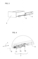
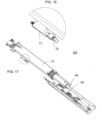
- the Fig. 15 to 18 show in perspective and in detail a further embodiment variant of the pull-out guide 1.
- This embodiment variant differs from the previous one in the design of the drive device 6.
- the drive device 6 is designed as a pull-in device 69
- the drive device 6 is designed as an ejection device 61.
- the drive device 6 combines both functions and functions both as an ejection device 61 and as a retraction device 69.
- the pull-out guide 1 is in the closed position SS, whereas in Fig. 17 the pull-out guide is shown in an open position OS.
- the stop element 72 lies on the stop counterpart 60 of the drive device 6.
- the stop element 72 is spaced from the stop counterpart 60 and thus released.
- Said stop counterpart 60 can be formed on a catch lever.
- the catch lever engages around the driver 74 of the stop element 72 and holds it in a form-fitting manner.
- the positive connection is canceled by pivoting the catch lever.
- drawer rail 12 serves as a connecting device for connecting the drawer container 10 to the drawer rail 5.
- the Fig. 19 to 38 show a first exemplary embodiment of a depth adjustment device 7 in different representations, perspectives, (partial) sections and details.
- Fig. 19 the components of the depth adjustment device 7 can be seen in an exploded view.
- the carrier 71 is designed as a, preferably metallic, curved bracket.
- This carrier 71 has a base region 711 and two holding tabs 712, which protrude essentially at right angles from the base region 711, each with guide openings 713 formed therein.
- an opening 714 for the locking element 7c is formed in the carrier 71.
- the stop element 72 is mounted in the guide openings 713 so as to be displaceable along the longitudinal axis L.
- the stop element 72 has a bolt-shaped driver 74 and a movement transmission area 75.
- the movement transmission area 75 is designed as an external thread 76 wound around the axis of rotation D.
- the stop element 72 has lateral projections 721. These projections 721, together with corresponding recesses in the area of the guide opening 713, form an anti-rotation mechanism for the stop element 72 in the carrier 71, so that the stop element 72 does not turn over the axis of rotation D can rotate.
- the depth adjustment wheel 73 is at least partially sleeve-shaped around the axis of rotation D and has an elongated opening with an internal thread 77 wound around the axis of rotation D.
- This internal thread 77 corresponds to the external thread 76 of the motion transmission area 75 of the stop element 72.
- On its outside - in particular on its lateral surface - the depth adjustment wheel has a knurl 79.
- This knurling 79 is lamellar or rib-shaped, with the lamellar or ribs extending along the longitudinal axis L.
- Locking recesses 7b are formed on the depth adjustment wheel 73 (these correspond to the “slat valleys”). These locking recesses 7b correspond to the locking knob 7a of the locking element 7c. When turning the depth adjustment wheel 73, a “ratcheting feeling” is created via this latching knob 7a.
- the depth adjustment wheel is 72 held in its position by the locking element 7c, so that it cannot rotate around the stop element 72 when vibrations occur and would thereby undesirably adjust the depth position or the front panel gap F.
- Fig. 20 The depth adjustment device is shown in an assembled state.
- the stop element 72 is guided through the two guide openings 713 and the depth adjustment wheel 73 is rotatably mounted on the stop element 72, with movement of the depth adjustment wheel 73 along the longitudinal axis L being prevented by the retaining tabs 712 of the carrier 71.
- Fig. 21 shows again the same representation as Fig. 20 .
- Fig. 22 a better view of the depth adjustment wheel 73 is given. It can be seen that the depth adjustment wheel 73 has a recess 78. This is advantageous for the production of the depth adjustment wheel 73 and its internal thread 77 in a plastic injection molding process.
- Fig. 23 shows a view through this recess 78 of the depth adjustment wheel 23, with a small part of the internal thread 77 and a larger area of the external thread 76 being visible. The knurling 79 on the lateral surface of the depth adjustment wheel 23 is also clearly visible.
- Fig. 23 The detail according to Fig. 23 comes from the perspective view of the depth adjustment device 7 from Fig. 24 .
- the Fig. 25 and 26 show the depth adjustment device 7 cut off in the middle from different perspectives.
- Fig. 27 It can be seen that the stop element 72 is flattened on one side in the area of the external thread 76. This makes the rotation of the depth adjustment wheel 73 on the external thread 76 smoother because there is less friction.
- Fig. 28 shows a to Fig. 29 relevant detail of the depth adjustment device 7.
- the depth adjustment wheel 73 is shown in different perspectives.
- the thread elevations of the internal thread 77 stand out from the remaining inner surface of the depth adjustment wheel 73 in the direction of the axis of rotation D. This enables a relatively smooth rotational movement.
- the internal thread 77 is not formed on the full circumference, but only on half the circumference of the inner surface of the depth adjustment wheel 73.
- the recess 78 is located radially opposite this internal thread 77.
- Fig. 35 a section through the depth adjustment device 7 is shown, which is shown in Fig. 36 is shown.
- the internal thread 77 as well as the corresponding external thread 76 are clearly visible.
- the locking element 7c with its locking knob 7a, the bolt-shaped driver 74 and the carrier 71 can also be seen.
- the depth adjusting device 7 By rotating the adjusting wheel 73 about the axis of rotation D, the depth adjusting device 7 reaches the position according to 37 and 38 .
- Fig. 39 shows a further exemplary embodiment of a depth adjustment device 7.
- the stop element 72 including the driver 74 and movement transmission area 75 is designed practically identically to the previous exemplary embodiment.
- Fig. 40 is the depth adjustment device 7 according to Fig. 39 shown in assembled condition.
- Fig. 42 shows a top view of a half-cut depth adjustment wheel 73. This provides a clear view of the three separate internal threads 77, which are each arranged radially opposite a recess 78.
- the in Fig. 44 marked cut is in Fig. 45 shown.
- the three half-shell-shaped internal threads 77 are each opposite the recesses 78 arranged and correspond to the external thread 76 of the stop element 72.
- the Fig. 46 to 49 show a third exemplary embodiment of the depth adjustment device 7.
- an expanding element 722 is arranged at the end of the stop element 72 remote from the driver. This prevents the stop element 72 from being able to be completely unscrewed from the carrier 71 and the depth adjustment wheel 73.
- Fig. 48 the different design of the locking element 7c can be seen. According to the details Fig. 49 the locking knob 7a is held between the lamellar knurls 79 on the lateral surface of the depth adjustment wheel 73.
Abstract
Ausziehführung (1) für ein relativ zu einem Möbelkorpus (3) bewegbares Möbelteil (2), insbesondere für eine Schublade, mit einer mit dem Möbelkorpus (3) zu verbindenden Korpusschiene (4), einer an der Korpusschiene (4) bewegbar gelagerten Ladenschiene (5), welche mit dem bewegbaren Möbelteil (2) verbindbar ist und eine Längsachse (L) aufweist, wobei die Ladenschiene (5) entlang der Längsachse (L) in Öffnungs- und Schließrichtung (OR, SR) des bewegbaren Möbelteils (2) bewegbar ist, einer Antriebsvorrichtung (6) zum Bewegen der Ladenschiene (5) und des damit verbindbaren bewegbaren Möbelteils (2) zumindest in einem Teilbereich des Bewegungsweges zwischen einer Schließstellung (SS) und einer Offenstellung (OS) und einer Tiefenverstelleinrichtung (7) zum Einstellen der Schließstellung (SS) der Ladenschiene (5) relativ zur Korpusschiene (4), wobei die Tiefenverstelleinrichtung (7) einen Träger (71), ein relativ zum Träger (71) entlang der Längsachse (L) bewegbares Anschlagelement (72) und ein am Träger (71) um eine Drehachse (D) drehbar gelagertes Tiefenverstellrad (73) zum Bewegen des Anschlagelements (72) entlang der Längsachse (L) aufweist, wobei die Drehachse (D) des Tiefenverstellrads (73) parallel zur Längsachse (L) ausgerichtet ist, die Antriebsvorrichtung (6) an der Korpusschiene (4) montiert ist, der Träger (71) der Tiefenverstelleinrichtung (7) an der Ladenschiene (5) montiert ist und das Anschlagelement (72) in Schließstellung (SS) an einem Anschlag-Gegenstück (60) der Antriebsvorrichtung (6) anliegt und während des Bewegungswegs von der Schließstellung (SS) in eine Offenstellung (OS) vom Anschlag-Gegenstück (60) lösbar ist.Pull-out guide (1) for a furniture part (2) that can be moved relative to a furniture body (3), in particular for a drawer, with a body rail (4) to be connected to the furniture body (3), a drawer rail movably mounted on the body rail (4) ( 5), which can be connected to the movable furniture part (2) and has a longitudinal axis (L), the drawer rail (5) being movable along the longitudinal axis (L) in the opening and closing directions (OR, SR) of the movable furniture part (2). is, a drive device (6) for moving the drawer rail (5) and the movable furniture part (2) that can be connected to it at least in a partial area of the movement path between a closed position (SS) and an open position (OS) and a depth adjustment device (7) for adjusting the Closed position (SS) of the drawer rail (5) relative to the body rail (4), the depth adjustment device (7) having a carrier (71), a stop element (72) movable relative to the carrier (71) along the longitudinal axis (L) and a stop element (72) on the carrier (71) has a depth adjustment wheel (73) rotatably mounted about an axis of rotation (D) for moving the stop element (72) along the longitudinal axis (L), the axis of rotation (D) of the depth adjustment wheel (73) being aligned parallel to the longitudinal axis (L), the drive device (6) is mounted on the body rail (4), the carrier (71) of the depth adjustment device (7) is mounted on the drawer rail (5) and the stop element (72) in the closed position (SS) on a stop counterpart (60 ) rests on the drive device (6) and can be released from the stop counterpart (60) during the movement path from the closed position (SS) to an open position (OS).
Description
Die vorliegende Erfindung betrifft eine Ausziehführung für ein relativ zu einem Möbelkorpus bewegbares Möbelteil, insbesondere für eine Schublade, mit einer mit dem Möbelkorpus zu verbindenden Korpusschiene, einer an der Korpusschiene bewegbar gelagerten Ladenschiene, welche mit dem bewegbaren Möbelteil verbindbar ist und eine Längsachse aufweist, wobei die Ladenschiene entlang der Längsachse in Öffnungs- und Schließrichtung des bewegbaren Möbelteils bewegbar ist, einer Antriebsvorrichtung zum Bewegen der Ladenschiene und des damit verbindbaren bewegbaren Möbelteils zumindest in einem Teilbereich des Bewegungsweges zwischen einer Schließstellung und einer Offenstellung und einer Tiefenverstelleinrichtung zum Einstellen der Schließstellung der Ladenschiene relativ zur Korpusschiene, wobei die Tiefenverstelleinrichtung einen Träger, ein relativ zum Träger entlang der Längsachse bewegbares Anschlagelement und ein am Träger um eine Drehachse drehbar gelagertes Tiefenverstellrad zum Bewegen des Anschlagelements entlang der Längsachse aufweist. Zudem betrifft die vorliegende Erfindung ein Möbel mit einem Möbelkorpus, einem bewegbaren Möbelteil und einer solchen Ausziehführung.The present invention relates to a pull-out guide for a furniture part that can be moved relative to a furniture body, in particular for a drawer, with a body rail to be connected to the furniture body, a drawer rail movably mounted on the body rail, which can be connected to the movable furniture part and has a longitudinal axis, wherein the drawer rail is movable along the longitudinal axis in the opening and closing direction of the movable furniture part, a drive device for moving the drawer rail and the movable furniture part connectable thereto at least in a partial area of the movement path between a closed position and an open position and a depth adjustment device for adjusting the closed position of the drawer rail relatively to the body rail, wherein the depth adjustment device has a carrier, a stop element movable relative to the carrier along the longitudinal axis and a depth adjustment wheel rotatably mounted on the carrier about an axis of rotation for moving the stop element along the longitudinal axis. In addition, the present invention relates to a piece of furniture with a furniture body, a movable furniture part and such a pull-out guide.
Bei Ausziehführungen und generell bei Möbeln ist es wichtig, dass im verbauten Zustand die einzelnen Komponenten ein möglichst einheitliches Design haben und regelmäßig angeordnet sind. Vor allem sollen die Möbelfronten ein einheitliches Blendenbild ergeben. Das heißt, alle Möbelfronten von nebeneinander oder übereinander angeordneten Schubladen sollen in der jeweiligen Schließstellung in derselben (vertikalen) Ebene liegen. Um dies bei Möbeln mit verbauten Ausziehführungen bewerkstelligen zu können, sind sogenannte Tiefenverstelleinrichtungen vorgesehen, mit welchen die in der Schließstellung gegebene Relativposition zwischen Korpusschiene und Ladenschiene (in horizontaler Richtung) verändert und eingestellt werden kann.When it comes to pull-out runners and furniture in general, it is important that when installed, the individual components have as uniform a design as possible and are arranged regularly. Above all, the furniture fronts should create a uniform appearance. This means that all furniture fronts of drawers arranged next to one another or one above the other should be in the respective one Closed position lie in the same (vertical) plane. In order to be able to accomplish this on furniture with built-in pull-out guides, so-called depth adjustment devices are provided, with which the relative position between the body rail and the drawer rail (in the horizontal direction) given in the closed position can be changed and adjusted.
Die
Eine ganz ähnliche Vorrichtung geht aus der
Demgegenüber geht ein Beispiel für ein Möbel mit einer Tiefenverstellmöglichkeit zum Einstellen der Relativposition zwischen der Ladenschiene und der Korpusschiene aus der
In ganz ähnlicher Weise ist die Ausstoßvorrichtung gemäß der
Eine ähnliche Ausführungsvariante geht aus dem in der
Die
Die Aufgabe der vorliegenden Erfindung besteht darin, eine zum bekannten Stand der Technik alternative Ausziehführung zu schaffen. Insbesondere sollen die beim Stand der Technik gegeben Nachteile möglichst behoben bzw. vermieden werden.The object of the present invention is to create an alternative pull-out guide to the known prior art. In particular, the disadvantages of the prior art should be eliminated or avoided as far as possible.
Dies wird durch eine Ausziehführung mit den Merkmalen von Anspruch 1 gelöst.This is solved by a pull-out guide with the features of
Bei der erfindungsgemäßen Ausziehführung ist vorgesehen, dass die Drehachse des Tiefenverstellrads parallel zur Längsachse ausgerichtet ist. Dadurch kann auf einfache Art und Weise eine Betätigung des Tiefenverstellrads erfolgen.In the pull-out guide according to the invention it is provided that the axis of rotation of the depth adjustment wheel is aligned parallel to the longitudinal axis. This allows the depth adjustment wheel to be operated in a simple manner.
Weiters ist erfindungsgemäß vorgesehen, dass die Antriebsvorrichtung an der Korpusschiene montiert ist. Dadurch kann die Antriebsvorrichtung dem Möbelkorpus zugeordnet bleiben und muss beim Öffnen und Schließen nicht mit dem bewegbaren Möbelteil mitbewegt werden Erfindungsgemäß ist auch vorgesehen, dass der Träger der Tiefenverstelleinrichtung an der Ladenschiene montiert ist. Dadurch kann die Tiefenverstelleinrichtung einfach erreicht werden. Vor allem bei geöffnetem bewegbarem Möbelteil kann die Tiefenverstelleinrichtung einfach und schnell mit der Hand erreicht werden. Die Tiefenverstelleinrichtung ist also nicht irgendwo unzugänglich in der Tiefe des Möbelkorpus "versteckt".Furthermore, according to the invention it is provided that the drive device is mounted on the body rail. As a result, the drive device can remain assigned to the furniture body and does not have to be moved with the movable furniture part when opening and closing According to the invention it is also provided that the carrier of the depth adjustment device is mounted on the drawer rail. This means that the depth adjustment device can be easily accessed. The depth adjustment device can be easily and quickly reached by hand, especially when the movable furniture part is open. The depth adjustment device is therefore not “hidden” somewhere inaccessible in the depths of the furniture body.
Zudem ist erfindungsgemäß vorgesehen, dass das Anschlagelement in Schließstellung an einem Anschlag-Gegenstück der Antriebsvorrichtung anliegt und während des Bewegungswegs von der Schließstellung in eine Offenstellung vom Anschlag-Gegenstück lösbar ist. Somit muss das Anschlagelement nicht in ständigem Kontakt mit dem Anschlag-Gegenstück stehen. Das Anschlagelement muss also nicht den gesamten Öffnungs- und Schließweg der Ladenschiene mitmachen. Anders ausgedrückt ist das Anschlagelement lösbar mit dem Anschlag-Gegenstück verbunden. Konkret wird durch diese Ausgestaltung erreicht, dass das Anschlagelement ab Erreichen einer bestimmten Offenstellung vom Anschlag-Gegenstück der Antriebsvorrichtung beabstandet ist. Das Anschlagelement bewegt sich also nur auf einem Teilbereich des Öffnungs- und Schließweges mit dem Anschlag-Gegenstück mit.In addition, it is provided according to the invention that the stop element rests against a stop counterpart of the drive device in the closed position and can be detached from the stop counterpart during the movement path from the closed position to an open position. The stop element therefore does not have to be in constant contact with the stop counterpart. The stop element does not have to follow the entire opening and closing path of the shutter rail. In other words, the stop element is detachably connected to the stop counterpart. Specifically, this configuration ensures that the stop element is spaced from the stop counterpart of the drive device once a certain open position has been reached. The stop element therefore only moves with the stop counterpart over a partial area of the opening and closing path.
Bevorzugte Ausführungsbeispiele der vorliegenden Erfindung sind in den abhängigen Ansprüchen näher definiert.Preferred embodiments of the present invention are defined in more detail in the dependent claims.
Für eine einfache Ausbildung der Tiefenverstelleinrichtung ist vorgesehen, dass das Anschlagelement einen Mitnehmer und einen mit dem Tiefenverstellrad in Verbindung stehenden Bewegungsübertragungsbereich aufweist.For a simple design of the depth adjustment device, it is provided that the stop element has a driver and has a motion transmission area connected to the depth adjustment wheel.
Der Mitnehmer kann als einfache, möglichst flache Anschlagfläche ausgebildet sein. Bevorzugt ist allerdings vorgesehen, dass der Mitnehmer bolzenförmig ausgebildet ist.The driver can be designed as a simple, flat stop surface. However, it is preferably provided that the driver is bolt-shaped.
Es ist bevorzugt vorgesehen, dass sich der bolzenförmige Mitnehmer rechtwinkelig zur Längsachse und - in im Möbelkorpus eingebautem Zustand - in vertikaler Richtung erstreckt.It is preferably provided that the bolt-shaped driver extends at right angles to the longitudinal axis and - when installed in the furniture body - in the vertical direction.
Um eine Bewegungsumwandlung zu ermöglichen, ist bevorzugt vorgesehen, dass der Bewegungsübertragungsbereich als um die Drehachse gewundenes Außengewinde ausgebildet ist.In order to enable movement conversion, it is preferably provided that the movement transmission area is designed as an external thread wound around the axis of rotation.
Gemäß einem bevorzugten Ausführungsbeispiel ist vorgesehen, dass das Tiefenverstellrad zumindest bereichsweise hülsenförmig um die Drehachse ausgebildet ist.According to a preferred exemplary embodiment, it is provided that the depth adjustment wheel is at least partially sleeve-shaped around the axis of rotation.
Besonders bevorzugt ist vorgesehen, dass das Tiefenverstellrad ein um die Drehachse gewundenes Innengewinde aufweist, wobei dieses Innengewinde mit dem Außengewinde des Bewegungsübertragungsbereichs korrespondiert.It is particularly preferably provided that the depth adjustment wheel has an internal thread wound around the axis of rotation, this internal thread corresponding to the external thread of the motion transmission area.
Weiters ist bevorzugt vorgesehen, dass das Innengewinde an einer einen Winkel von maximal 180 ° um die Drehachse einnehmenden Innenoberfläche des Tiefenverstellrads ausgebildet ist und das Tiefenverstellrad in jenem Bereich eine Ausnehmung aufweist, welche der besagten Innenoberfläche radial gegenüberliegt. Anders ausgedrückt weist das Tiefenverstellrad in dem dem Innengewinde radial gegenüberliegenden Bereich eine Freistellung (Ausnehmung bzw. Öffnung) auf. Diese Freistellung dient dazu, dass das Tiefenverstellrad und dessen Gewinde bei der Herstellung in einem Spritzgießwerkzeug nicht umständlich ausgedreht werden muss. Die Entformung des Tiefenverstellrads ist dadurch wesentlich einfacher.Furthermore, it is preferably provided that the internal thread is formed on an inner surface of the depth adjustment wheel which occupies an angle of a maximum of 180 ° about the axis of rotation and that the depth adjustment wheel has a recess in that area which is radially opposite the said inner surface. Expressed differently The depth adjustment wheel has an exemption (recess or opening) in the area radially opposite the internal thread. This exemption ensures that the depth adjustment wheel and its thread do not have to be laboriously turned out during production in an injection molding tool. This makes demoulding the depth adjustment wheel much easier.
Besonders bevorzugt ist vorgesehen, dass das Tiefenverstellrad einen Betätigungsbereich aufweist, der von der um die Drehachse ausgebildeten Mantelfläche des Tiefenverstellrads gebildet ist. Dieser Betätigungsbereich ist daher nicht an einer Stirnfläche des Tiefenverstellrads ausgebildet, sondern an dessen Mantelfläche. Dadurch kann das Tiefenverstellrad direkt manuell, ohne Werkzeug gedreht und somit betätigt werden.It is particularly preferably provided that the depth adjustment wheel has an actuation area which is formed by the lateral surface of the depth adjustment wheel formed around the axis of rotation. This actuation area is therefore not formed on an end face of the depth adjustment wheel, but on its lateral surface. This means that the depth adjustment wheel can be turned and operated manually without tools.
Gemäß einem bevorzugten Ausführungsbeispiel ist vorgesehen, dass das Tiefenverstellrad an seiner Außenseite, vorzugsweise an seiner Mantelfläche, eine, vorzugsweise entlang der Längsachse ausgerichtete, Rändelung aufweist. Dadurch kann das Tiefenverstellrad besser mit den Fingern gegriffen und betätigt werden.According to a preferred exemplary embodiment, it is provided that the depth adjustment wheel has a knurl on its outside, preferably on its lateral surface, preferably aligned along the longitudinal axis. This makes it easier to grip and operate the depth adjustment wheel with your fingers.
Es ist bevorzugt vorgesehen, dass die Tiefenverstelleinrichtung eine Einrastnoppe und mit der Einrastnoppe korrespondierende, vorzugsweise in regelmäßigen Abständen um die Längsachse angeordnete, Einrastvertiefungen aufweist. Dadurch kann beim Betätigen ein "Ratschgefühl" erzeugt werden. Der Bediener kann also besser einschätzen, wie weit das Tiefenverstellrad bereits gedreht wurde. Jedes Einrasten in eine weitere Einrastvertiefung entspricht einer weiteren Tiefenveränderung um eine bestimmte Distanz (z. B. 0,1 mm bis 0,5 mm).It is preferably provided that the depth adjustment device has a latching knob and latching recesses corresponding to the latching knob, preferably arranged at regular intervals around the longitudinal axis. This can create a “rattling” feeling when actuated. The operator can therefore better estimate how far the depth adjustment wheel has already been turned. Each snap into another snap recess corresponds to one further change in depth by a certain distance (e.g. 0.1 mm to 0.5 mm).
Um zu verhindern, dass sich das Anschlagelement beim Drehen des Tiefenverstellrads mitdreht, ist vorgesehen, dass die Tiefenverstelleinrichtung einen Anti-Dreh-Mechanismus für das Anschlagelement im Träger aufweist.In order to prevent the stop element from rotating when the depth adjustment wheel is rotated, it is provided that the depth adjustment device has an anti-rotation mechanism for the stop element in the carrier.
Die Antriebsvorrichtung kann als Einziehvorrichtung zum Einziehen des bewegbaren Möbelteils aus einer Offenstellung in eine Schließstellung ausgebildet sein.The drive device can be designed as a retraction device for retracting the movable furniture part from an open position into a closed position.
Bevorzugt kann die Einziehvorrichtung einen an der Korpusschiene angebrachten Träger, einen relativ zum Träger bewegbaren Einziehschlitten und einen mit dem Träger und dem Einziehschlitten verbundenen Einziehkraftspeicher aufweisen.Preferably, the pull-in device can have a carrier attached to the body rail, a pull-in slide that is movable relative to the carrier, and a pull-in force accumulator connected to the carrier and the pull-in slide.
Die Einziehvorrichtung kann auch einen Dämpfer zum Dämpfen der Einziehbewegung aufweisen, wodurch ein sanftes und leichtgängiges Schließen gewährleistet wird.The retraction device can also have a damper to dampen the retraction movement, ensuring gentle and smooth closing.
Alternativ (oder zusätzlich) zur Ausstoßvorrichtung kann vorgesehen sein, dass die Antriebsvorrichtung als Ausstoßvorrichtung zum Ausstoßen der Ladenschiene aus der Schließstellung in eine Offenstellung ausgebildet ist.As an alternative (or in addition) to the ejection device, it can be provided that the drive device is designed as an ejection device for ejecting the drawer rail from the closed position into an open position.
Bevorzugt ist vorgesehen, dass die Ausstoßvorrichtung einen an der Korpusschiene angebrachten Träger, einen relativ zum Träger bewegbaren Ausstoßschlitten und einen mit dem Träger und dem Ausstoßschlitten verbundenen Ausstoßkraftspeicher aufweist.It is preferably provided that the ejection device has a carrier attached to the body rail, an ejection carriage that is movable relative to the carrier and an ejection force accumulator connected to the carrier and the ejection carriage.
Bevorzugt ist auch vorgesehen, dass die Ausstoßvorrichtung eine Verriegelungsvorrichtung zum Verriegeln des Ausstoßschlittens in einer Verriegelungsstellung aufweist. Durch Überdrücken des bewegbaren Möbelteils in eine hinter der Schließstellung liegende Überdrückstellung wird die Verriegelungsvorrichtung entriegelt und der Ausstoßkraftspeichert stößt den Ausstoßschlitten samt bewegbarem Möbelteil in Öffnungsrichtung aus. Die Verriegelungsvorrichtung kann eine herzkurvenförmige Verriegelungsbahn und einen in dieser Verriegelungsbahn bewegbaren Verriegelungszapfen aufweisen. Es sind aber auch andere Verriegelungsvarianten möglich, beispielsweise in Form des Kugelschreiberprinzips.It is also preferably provided that the ejection device has a locking device for locking the ejection carriage in a locking position. By over-pressing the movable furniture part into an over-pressing position behind the closed position, the locking device is unlocked and the ejection force store ejects the ejection carriage together with the movable furniture part in the opening direction. The locking device can have a heart-shaped locking track and a locking pin that can be moved in this locking track. However, other locking variants are also possible, for example in the form of the ballpoint pen principle.
Weiters ist bevorzugt vorgesehen, dass in Schließstellung der Ausstoßschlitten der Ausstoßvorrichtung über das am Ausstoßschlitten ausgebildete Anschlag-Gegenstück am Anschlagelement der Tiefenverstelleinrichtung anliegt. Wenn sich der Ausstoßschlitten in der Schließstellung an einer bestimmten Relativposition zur Ladenschiene (und somit zum Möbelkorpus) befindet, kann durch Verstellen des Anschlagselements entlang der Längsachse die Relativposition der Ladenschiene zur Korpusschiene verändert werden. Dies bewirkt wiederum, dass die Tiefenposition des bewegbaren Möbelteils und dessen Frontblende relativ zum Möbelkorpus verstellt wird und entsprechend einstellbar ist.Furthermore, it is preferably provided that in the closed position the ejection carriage of the ejection device rests on the stop element of the depth adjustment device via the stop counterpart formed on the ejection carriage. If the ejection carriage is in the closed position at a certain relative position to the drawer rail (and thus to the furniture body), the relative position of the drawer rail to the cabinet rail can be changed by adjusting the stop element along the longitudinal axis. This in turn causes the depth position of the movable furniture part and its front panel to be adjusted relative to the furniture body and can be adjusted accordingly.
Um ein sicheres Mitbewegen des Mitnehmers mit dem Ausstoßschlitten sowohl in Öffnungsrichtung als auch in Schließrichtung zu gewährleisten, ist bevorzugt vorgesehen, dass der Ausstoßschlitten einen das Anschlag-Gegenstück mitbildenden Fanghebel aufweist, welcher in Schließstellung den Mitnehmer des Anschlagelements umgreift und formschlüssig hält. Bei Erreichen einer bestimmten Offenstellung (z. B. nach einem Öffnungsweg von ca. 30 mm bis 120 mm) wird die lösbare Verbindung zwischen dem Fanghebel und dem Mitnehmer wieder aufgehoben.In order to ensure safe movement of the driver with the ejection carriage both in the opening direction and in the closing direction, it is preferably provided that the ejection carriage has a stop counterpart has co-forming catch lever, which in the closed position engages around the driver of the stop element and holds it in a form-fitting manner. When a certain open position is reached (e.g. after an opening distance of approx. 30 mm to 120 mm), the detachable connection between the catch lever and the driver is released again.
Schutz wird auch begeht für ein Möbel mit einem Möbelkorpus, einem bewegbaren Möbelteil und einer erfindungsgemäßen Ausziehführung.Protection is also provided for a piece of furniture with a furniture body, a movable furniture part and a pull-out guide according to the invention.
Besonders bevorzugt ist vorgesehen, dass das bewegbare Möbelteil über zwei an gegenüberliegenden Seiten des Möbelkorpus montierten, vorzugsweise spiegelsymmetrisch zueinander ausgebildeten, Ausziehführungen am Möbelkorpus bewegbar gelagert ist.Particularly preferably, it is provided that the movable furniture part is movably mounted on the furniture body via two pull-out guides mounted on opposite sides of the furniture body and preferably designed mirror-symmetrically to one another.
Weitere Einzelheiten und Vorteile der vorliegenden Erfindung werden anhand der Figurenbeschreibung unter Bezugnahme auf die in den Zeichnungen dargestellten Ausführungsbeispiele im Folgenden näher erläutert. Darin zeigen:
- Fig. 1
- schematisch ein Möbel mit mehreren übereinander angeordneten bewegbaren Möbelteilen in verschiedenen Stellungen,
- Fig. 2
- perspektivisch ein bewegbares Möbelteil mit zwei Ausziehführungen samt Antriebsvorrichtung,
- Fig. 3
- perspektivisch ein bewegbares Möbelteil samt Ausziehführung,
- Fig. 4
- ein Detail aus
Fig. 3 , - Fig. 5-10
- eine Draufsicht auf das bewegbare Möbelteil samt Ausziehführung mit der Tiefenverstelleinrichtung jeweils in unterschiedlichen Stellungen und Details der Tiefenverstelleinrichtungen,
- Fig. 11
- perspektivisch eine Ausziehführung mit einer ersten Variante der Antriebsvorrichtung,
- Fig. 12
- ein Detail aus
Fig. 11 , - Fig. 13
- einen vertikalen Schnitt durch die Ausziehführung gemäß
Fig. 11 , - Fig. 14
- ein Detail aus
Fig. 13 , - Fig. 15
- perspektivisch eine Ausziehführung in Schließstellung mit einer zweiten Variante der Antriebsvorrichtung,
- Fig. 16
- ein Detail aus
Fig. 15 , - Fig. 17
- die Ausziehführung gemäß
Fig. 15 in einer Offenstellung, - Fig. 18
- ein Detail aus
Fig. 17 , - Fig. 19-38
- unterschiedliche Darstellungen, Perspektiven, Schnitte und Details eines ersten Ausführungsbeispiels der Tiefenverstelleinrichtung,
- Fig. 39-45
- unterschiedliche Darstellungen, Perspektiven, Schnitte und Details eines zweiten Ausführungsbeispiels der Tiefenverstelleinrichtung und
- Fig. 46-49
- unterschiedliche Darstellungen, Perspektiven und Details eines dritten Ausführungsbeispiels der Tiefenverstelleinrichtung.
- Fig. 1
- schematically a piece of furniture with several movable furniture parts arranged one above the other in different positions,
- Fig. 2
- perspectively a movable furniture part with two pull-out guides including a drive device,
- Fig. 3
- in perspective a movable piece of furniture including a pull-out guide,
- Fig. 4
- a detail
Fig. 3 , - Fig. 5-10
- a top view of the movable furniture part including the pull-out guide with the depth adjustment device each in different positions and details of the depth adjustment devices,
- Fig. 11
- perspectively a pull-out guide with a first variant of the drive device,
- Fig. 12
- a detail
Fig. 11 , - Fig. 13
- a vertical section through the pull-out guide
Fig. 11 , - Fig. 14
- a detail
Fig. 13 , - Fig. 15
- perspectively a pull-out guide in the closed position with a second variant of the drive device,
- Fig. 16
- a detail
Fig. 15 , - Fig. 17
- the pull-out guide accordingly
Fig. 15 in an open position, - Fig. 18
- a detail
Fig. 17 , - Fig. 19-38
- different representations, perspectives, cuts and details of a first exemplary embodiment of the depth adjustment device,
- Fig. 39-45
- different representations, perspectives, cuts and details of a second embodiment of the depth adjustment device and
- Fig. 46-49
- different representations, perspectives and details of a third embodiment of the depth adjustment device.
In
Bei der obersten Schublade ist schematisch eine Antriebsvorrichtung 6 dargestellt. Die Antriebsvorrichtung 6 weist einen Träger 62 auf. In diesem Fall ist dieser Träger 62 an der Ladenschiene 5 angebracht. Erfindungsgemäß ist die Antriebsvorrichtung 6 aber - im Gegensatz zur
Wenn die Schublade von dieser Offenstellung OS in Schließrichtung SR bewegt wird, so verfährt der Verriegelungszapfen 68 in einem Schließabschnitt der Führungsbahn 67. Dabei wird der Ausstoßkraftspeicher 65 durch eine Relativbewegung zwischen Ausstoßschlitten 63 und Träger 62 gespannt.When the drawer is moved from this open position OS in the closing direction SR, the locking
In der Schließstellung SS (dritte Schublade von oben) ist der Ausstoßkraftspeicher 65 voll gespannt. Diese Schließstellung SS kann durch eine rein händische Schließbewegung erreicht werden. Alternativ kann die Schublade - wenn vorhanden - von der nur schematisch dargestellten und in die Ausziehführung 1 integrierten Einziehvorrichtung 69 in die Schließstellung SS bewegt bzw. eingezogen werden.In the closed position SS (third drawer from the top), the
Ausgehend von dieser Schließstellung SS gelangt die Schublade durch Drücken auf die Schublade in die Überdrückstellung ÜS (unterste Schublade in
In
Diese Antriebsvorrichtung 6 (bzw. dessen Träger 62) erstreckt sich in Schließrichtung SR der Schublade. Diese Schließrichtung entspricht auch der Längsachse L der Ladenschiene 5 bzw. der gesamten Ausziehführung 1. Vor allem bei kleineren oder schmaleren Schubladen 2 reicht es aus, wenn der Schublade nur eine Antriebsvorrichtung 6 zugeordnet ist. Diese kann (wie dargestellt) der rechtsseitigen Ausziehführung 1 (aber auch der linksseitigen Ausziehführung 1) zugeordnet sein.This drive device 6 (or its carrier 62) extends in the closing direction SR of the drawer. This closing direction also corresponds to the longitudinal axis L of the
In
In den
In
Wenn die Tiefenverstelleinrichtung 7 über das Tiefenverstellrad 73 betätigt wird, so wird das Anschlagelement 72 relativ zum Träger 71 linear bewegt. In
Wenn das Tiefenverstellrad 73 weiter in dieselbe Richtung gedreht wird, so ergibt sich bald eine Position wie in
Aus einem Vergleich der
In
In
Die
Es kann auch vorgesehen sein, dass die Antriebsvorrichtung 6 beide Funktionen vereint und sowohl als Ausstoßvorrichtung 61 als auch als Einziehvorrichtung 69 fungiert.It can also be provided that the
In
Besagtes Anschlag-Gegenstück 60 kann an einem Fanghebel ausgebildet sein. Der Fanghebel umgreift in Schließstellung SS den Mitnehmer 74 des Anschlagelements 72 hält diesen formschlüssig. Bei einer Bewegung in Öffnungsrichtung OR wird die formschlüssige Verbindung durch Verschwenken des Fanghebels aufgehoben.Said
In den
Die
In
Der Träger 71 ist als, vorzugsweise metallischer, gebogener Bügel ausgebildet. Dieser Träger 71 weist einen Basisbereich 711 und zwei, im Wesentlichen rechtwinkelig vom Basisbereich 711 abstehende Haltelaschen 712 mit jeweils darin ausgebildet Führungsöffnungen 713 auf. Zudem ist im Träger 71 eine Öffnung 714 für das Arretierelement 7c ausgebildet.The
Das Anschlagelement 72 ist in den Führungsöffnungen 713 entlang der Längsachse L verschiebbar gelagert. Das Anschlagelement 72 weist einen bolzenförmigen Mitnehmer 74 und einen Bewegungsübertragungsbereich 75 auf. Der Bewegungsübertragungsbereich 75 ist als um die Drehachse D gewundenes Außengewinde 76 ausgebildet.The
Zwischen dem Mitnehmer 74 und diesem Außengewinde 76 weist das Anschlagelement 72 seitliche Vorsprünge 721. Diese Vorsprünge 721 bilden zusammen mit korrespondierenden Vertiefungen im Bereich der Führungsöffnung 713 einen Anti-Dreh-Mechanismus für das Anschlagelement 72 im Träger 71, sodass sich das Anschlagelement 72 nicht um die Drehachse D drehen kann.Between the
Das Tiefenverstellrad 73 ist zumindest bereichsweise hülsenförmig um die Drehachse D ausgebildet und weist eine längliche Öffnung mit einem um die Drehachse D gewundenen Innengewinde 77 auf. Diese Innengewinde 77 korrespondiert mit dem Außengewinde 76 des Bewegungsübertragungsbereichs 75 des Anschlagelements 72. An seiner Außenseite - im Speziellen an seiner Mantelfläche - weist das Tiefenverstellrad eine Rändelung 79 auf. Diese Rändelung 79 ist lamellenförmig oder rippenförmig ausgebildet, wobei sich die Lamellen oder Rippen entlang der Längsachse L erstrecken.The
Am Tiefenverstellrad 73 sind Einrastvertiefungen 7b ausgebildet (diese stimmen mit den "Lamellentälern" überein). Diese Einrastvertiefungen 7b korrespondieren mit der Einrastnoppe 7a des Arretierelements 7c. Beim Drehen des Tiefenverstellrads 73 wird über diese Einrastnoppe 7a ein "Ratschgefühl" erzeugt. Zudem wird das Tiefenverstellrad 72 durch das Arretierelement 7c in seiner Stellung gehalten, sodass es sich nicht bei auftretenden Vibrationen von selbst um das Anschlagelement 72 drehen kann und dadurch ungewünscht die Tiefenposition bzw. den Frontblendenspalt F verstellen würde.Locking
In
In
Das Detail gemäß
Die
In
In den
In
Durch Drehen des Verstellrads 73 um die Drehachse D gelangt die Tiefenverstelleinrichtung 7 in die Position gemäß den
In
In den
Im Schnitt gemäß
Der in
Die
In
- 11
- AusziehführungPull-out guide
- 22
- bewegbaren Möbelteilmovable furniture part
- 33
- MöbelkorpusFurniture body
- 44
- KorpusschieneBody rail
- 55
- LadenschieneShop rail
- 66
- AntriebsvorrichtungDrive device
- 6060
- Anschlag-GegenstückStop counterpart
- 6161
- AusstoßvorrichtungEjector
- 6262
- Trägercarrier
- 6363
- AusstoßschlittenEjection carriage
- 6565
- AusstoßkraftspeicherEjection force storage
- 6666
- VerriegelungsvorrichtungLocking device
- 6767
- Führungsbahnguideway
- 6868
- VerriegelungszapfenLocking pin
- 6969
- EinziehvorrichtungRetraction device
- 77
- TiefenverstelleinrichtungDepth adjustment device
- 7171
- Trägercarrier
- 711711
- BasisbereichBasic area
- 712712
- Haltelaschenretaining tabs
- 713713
- FührungsöffnungenGuide openings
- 714714
- Öffnungopening
- 7272
- Anschlagelementstop element
- 721721
- VorsprüngeProjections
- 722722
- Aufspreizelementexpanding element
- 7373
- TiefenverstellradDepth adjustment wheel
- 7474
- Mitnehmertaker
- 7575
- BewegungsübertragungsbereichMotion transfer area
- 7676
- AußengewindeExternal thread
- 7777
- Innengewindeinner thread
- 7878
- Ausnehmungrecess
- 7979
- RändelungKnurling
- 7a7a
- EinrastnoppeSnap-in knob
- 7b7b
- EinrastvertiefungenSnap-in recesses
- 7c7c
- ArretierelementLocking element
- 88th
- MöbelFurniture
- 1010
- SchubbehältnisPush container
- 1111
- FrontblendeFront panel
- 1212
- SchubladenschieneDrawer runner
- LL
- LängsachseLongitudinal axis
- OROR
- ÖffnungsrichtungOpening direction
- SRS.R
- SchließrichtungClosing direction
- OSO.S
- Offenstellungopen position
- SSSS
- SchließstellungClosed position
- ÜSO.S
- Überdrückstellungoverpressure position
- DD
- DrehachseAxis of rotation
- FF
- FrontblendenspaltFront panel gap
Claims (15)
Applications Claiming Priority (3)
| Application Number | Priority Date | Filing Date | Title |
|---|---|---|---|
| ATA50388/2020A AT523789B1 (en) | 2020-05-07 | 2020-05-07 | Pull-out guide for a movable furniture part |
| EP21722748.7A EP4146041B1 (en) | 2020-05-07 | 2021-04-22 | Pull-out guide for a movable furniture part |
| PCT/AT2021/060137 WO2021222958A1 (en) | 2020-05-07 | 2021-04-22 | Pull-out guide for a movable furniture part |
Related Parent Applications (1)
| Application Number | Title | Priority Date | Filing Date |
|---|---|---|---|
| EP21722748.7A Division EP4146041B1 (en) | 2020-05-07 | 2021-04-22 | Pull-out guide for a movable furniture part |
Publications (2)
| Publication Number | Publication Date |
|---|---|
| EP4245187A2 true EP4245187A2 (en) | 2023-09-20 |
| EP4245187A3 EP4245187A3 (en) | 2023-12-13 |
Family
ID=75769515
Family Applications (2)
| Application Number | Title | Priority Date | Filing Date |
|---|---|---|---|
| EP21722748.7A Active EP4146041B1 (en) | 2020-05-07 | 2021-04-22 | Pull-out guide for a movable furniture part |
| EP23190508.4A Pending EP4245187A3 (en) | 2020-05-07 | 2021-04-22 | Pull-out guide for a movable furniture part |
Family Applications Before (1)
| Application Number | Title | Priority Date | Filing Date |
|---|---|---|---|
| EP21722748.7A Active EP4146041B1 (en) | 2020-05-07 | 2021-04-22 | Pull-out guide for a movable furniture part |
Country Status (8)
| Country | Link |
|---|---|
| US (1) | US20230059249A1 (en) |
| EP (2) | EP4146041B1 (en) |
| JP (1) | JP2023524540A (en) |
| CN (1) | CN115515458B (en) |
| AT (1) | AT523789B1 (en) |
| ES (1) | ES2965370T3 (en) |
| TW (1) | TWI767690B (en) |
| WO (1) | WO2021222958A1 (en) |
Citations (6)
| Publication number | Priority date | Publication date | Assignee | Title |
|---|---|---|---|---|
| EP2654507B1 (en) | 2010-12-22 | 2015-03-04 | Paul Hettich GmbH & Co. KG | Opening and closing device for movable furniture parts |
| EP2661194B1 (en) | 2011-01-05 | 2015-12-23 | Julius Blum GmbH | Device for adjusting a drawer frontpanel |
| DE202015104436U1 (en) | 2015-08-21 | 2016-11-22 | Grass Gmbh | Device for moving a movable furniture part in an opening direction with respect to a furniture body of a piece of furniture |
| AT512748B1 (en) | 2012-04-13 | 2017-04-15 | Blum Gmbh Julius | Adjustment device for adjusting a position of a drawer |
| DE102016120586A1 (en) | 2016-10-27 | 2018-05-03 | Paul Hettich Gmbh & Co. Kg | Furniture |
| EP1996046B1 (en) | 2006-03-22 | 2018-08-01 | Grass GmbH | Device for influencing the movement of furniture pieces which can be displaced in relation to each other and furniture |
Family Cites Families (7)
| Publication number | Priority date | Publication date | Assignee | Title |
|---|---|---|---|---|
| DE202010013193U1 (en) * | 2010-12-22 | 2012-03-26 | Paul Hettich Gmbh & Co. Kg | Opening and closing device for movable furniture parts and ejection device |
| AT511294B1 (en) * | 2011-04-11 | 2013-06-15 | Blum Gmbh Julius | drawer |
| AT515265B1 (en) * | 2014-01-09 | 2018-07-15 | Blum Gmbh Julius | drawer |
| TWI538638B (en) * | 2015-11-12 | 2016-06-21 | 川湖科技股份有限公司 | Drive mechanism and method for furniture parts |
| DE102016113116A1 (en) * | 2016-07-15 | 2018-01-18 | Paul Hettich Gmbh & Co. Kg | Drive device for a movable furniture part and method for opening and closing a movable furniture part |
| TW201932049A (en) * | 2018-01-18 | 2019-08-16 | 川湖科技股份有限公司 | Furniture and slide rail assembly thereof |
| CN109077466B (en) * | 2018-10-18 | 2021-06-25 | 王鸳 | Tea table with storage function |
-
2020
- 2020-05-07 AT ATA50388/2020A patent/AT523789B1/en active
-
2021
- 2021-04-22 JP JP2022567325A patent/JP2023524540A/en active Pending
- 2021-04-22 EP EP21722748.7A patent/EP4146041B1/en active Active
- 2021-04-22 ES ES21722748T patent/ES2965370T3/en active Active
- 2021-04-22 WO PCT/AT2021/060137 patent/WO2021222958A1/en unknown
- 2021-04-22 CN CN202180033418.0A patent/CN115515458B/en active Active
- 2021-04-22 EP EP23190508.4A patent/EP4245187A3/en active Pending
- 2021-05-06 TW TW110116320A patent/TWI767690B/en active
-
2022
- 2022-10-31 US US17/977,579 patent/US20230059249A1/en active Pending
Patent Citations (6)
| Publication number | Priority date | Publication date | Assignee | Title |
|---|---|---|---|---|
| EP1996046B1 (en) | 2006-03-22 | 2018-08-01 | Grass GmbH | Device for influencing the movement of furniture pieces which can be displaced in relation to each other and furniture |
| EP2654507B1 (en) | 2010-12-22 | 2015-03-04 | Paul Hettich GmbH & Co. KG | Opening and closing device for movable furniture parts |
| EP2661194B1 (en) | 2011-01-05 | 2015-12-23 | Julius Blum GmbH | Device for adjusting a drawer frontpanel |
| AT512748B1 (en) | 2012-04-13 | 2017-04-15 | Blum Gmbh Julius | Adjustment device for adjusting a position of a drawer |
| DE202015104436U1 (en) | 2015-08-21 | 2016-11-22 | Grass Gmbh | Device for moving a movable furniture part in an opening direction with respect to a furniture body of a piece of furniture |
| DE102016120586A1 (en) | 2016-10-27 | 2018-05-03 | Paul Hettich Gmbh & Co. Kg | Furniture |
Also Published As
| Publication number | Publication date |
|---|---|
| AT523789A1 (en) | 2021-11-15 |
| EP4146041B1 (en) | 2023-08-23 |
| AT523789B1 (en) | 2024-04-15 |
| EP4146041A1 (en) | 2023-03-15 |
| US20230059249A1 (en) | 2023-02-23 |
| JP2023524540A (en) | 2023-06-12 |
| TWI767690B (en) | 2022-06-11 |
| WO2021222958A1 (en) | 2021-11-11 |
| TW202205999A (en) | 2022-02-16 |
| CN115515458B (en) | 2024-01-02 |
| EP4245187A3 (en) | 2023-12-13 |
| ES2965370T3 (en) | 2024-04-15 |
| CN115515458A (en) | 2022-12-23 |
Similar Documents
| Publication | Publication Date | Title |
|---|---|---|
| EP1959792B1 (en) | Piece of furniture having at least a first and a second furniture part | |
| DE19935120C2 (en) | Device for opening and closing a drawer | |
| EP2252178B1 (en) | Immobilization device for locking a furniture part movably supported in or on a piece of furniture | |
| EP1978842B1 (en) | Drive mechanism for a furniture part mounted in a movable manner on a piece of furniture | |
| AT521260B1 (en) | Guide system for guiding a movably mounted door leaf | |
| WO2008131466A1 (en) | Spring buffer for a piece of furniture | |
| AT504765B1 (en) | EJECTOR LEVER FOR AN EJECTOR | |
| DE202005006724U1 (en) | Drawer mounting system comprises carcass rail, drawer rail and optionally intermediate connecting rail, gap between front of drawer and its front panel being adjusting using knurled screw in mounting attached to drawer rail | |
| EP3289155A1 (en) | Ejection device for a movable furniture part | |
| AT517603A4 (en) | Feeding device for movable furniture parts | |
| WO2020186276A1 (en) | Drive device for a moveable furniture part | |
| EP2560520B1 (en) | Ejector for ejecting a movable furniture part | |
| DE202007006549U1 (en) | Spring buffer for a furniture | |
| EP3941313B1 (en) | Drive device for a moveable furniture part | |
| EP3307974B1 (en) | Push-out device for a movable furniture part | |
| EP4146041B1 (en) | Pull-out guide for a movable furniture part | |
| EP3518707B1 (en) | Retraction device for a drawer pullout | |
| EP3945936B1 (en) | Retraction or ejection device | |
| DE10105847B4 (en) | Carrying device for pull-out furniture floor | |
| EP3578737A1 (en) | Door for a domestic appliance with a movable door handle fixed to both sides of a wall element of the door, and domestic appliance | |
| DE4103923C2 (en) | ||
| EP3745916B1 (en) | Arrangement of sliding rails, railsynchronisationdevice and actuacting pin | |
| DE202011104525U1 (en) | Furniture and device for moving a furniture part | |
| WO2017079771A1 (en) | Drive device for a movable furniture part |
Legal Events
| Date | Code | Title | Description |
|---|---|---|---|
| PUAI | Public reference made under article 153(3) epc to a published international application that has entered the european phase |
Free format text: ORIGINAL CODE: 0009012 |
|
| STAA | Information on the status of an ep patent application or granted ep patent |
Free format text: STATUS: THE APPLICATION HAS BEEN PUBLISHED |
|
| AC | Divisional application: reference to earlier application |
Ref document number: 4146041 Country of ref document: EP Kind code of ref document: P |
|
| AK | Designated contracting states |
Kind code of ref document: A2 Designated state(s): AL AT BE BG CH CY CZ DE DK EE ES FI FR GB GR HR HU IE IS IT LI LT LU LV MC MK MT NL NO PL PT RO RS SE SI SK SM TR |
|
| REG | Reference to a national code |
Ref country code: DE Ref legal event code: R079 Free format text: PREVIOUS MAIN CLASS: A47B0088453000 Ipc: A47B0088407000 |
|
| P01 | Opt-out of the competence of the unified patent court (upc) registered |
Effective date: 20231004 |
|
| PUAL | Search report despatched |
Free format text: ORIGINAL CODE: 0009013 |
|
| AK | Designated contracting states |
Kind code of ref document: A3 Designated state(s): AL AT BE BG CH CY CZ DE DK EE ES FI FR GB GR HR HU IE IS IT LI LT LU LV MC MK MT NL NO PL PT RO RS SE SI SK SM TR |
|
| RIC1 | Information provided on ipc code assigned before grant |
Ipc: A47B 88/453 20170101ALI20231103BHEP Ipc: A47B 88/407 20170101AFI20231103BHEP |