EP4245119A1 - Tube rail cart - Google Patents
Tube rail cart Download PDFInfo
- Publication number
- EP4245119A1 EP4245119A1 EP23159960.6A EP23159960A EP4245119A1 EP 4245119 A1 EP4245119 A1 EP 4245119A1 EP 23159960 A EP23159960 A EP 23159960A EP 4245119 A1 EP4245119 A1 EP 4245119A1
- Authority
- EP
- European Patent Office
- Prior art keywords
- platform
- tube rail
- rail cart
- locking mechanism
- cart according
- Prior art date
- Legal status (The legal status is an assumption and is not a legal conclusion. Google has not performed a legal analysis and makes no representation as to the accuracy of the status listed.)
- Granted
Links
Images



Classifications
-
- A—HUMAN NECESSITIES
- A01—AGRICULTURE; FORESTRY; ANIMAL HUSBANDRY; HUNTING; TRAPPING; FISHING
- A01D—HARVESTING; MOWING
- A01D45/00—Harvesting of standing crops
- A01D45/006—Harvesting of standing crops of tomatoes
-
- A—HUMAN NECESSITIES
- A01—AGRICULTURE; FORESTRY; ANIMAL HUSBANDRY; HUNTING; TRAPPING; FISHING
- A01D—HARVESTING; MOWING
- A01D46/00—Picking of fruits, vegetables, hops, or the like; Devices for shaking trees or shrubs
- A01D46/20—Platforms with lifting and lowering devices
-
- B—PERFORMING OPERATIONS; TRANSPORTING
- B61—RAILWAYS
- B61D—BODY DETAILS OR KINDS OF RAILWAY VEHICLES
- B61D15/00—Other railway vehicles, e.g. scaffold cars; Adaptations of vehicles for use on railways
-
- B—PERFORMING OPERATIONS; TRANSPORTING
- B61—RAILWAYS
- B61D—BODY DETAILS OR KINDS OF RAILWAY VEHICLES
- B61D3/00—Wagons or vans
- B61D3/04—Wagons or vans with movable floors, e.g. rotatable or floors which can be raised or lowered
-
- B—PERFORMING OPERATIONS; TRANSPORTING
- B66—HOISTING; LIFTING; HAULING
- B66F—HOISTING, LIFTING, HAULING OR PUSHING, NOT OTHERWISE PROVIDED FOR, e.g. DEVICES WHICH APPLY A LIFTING OR PUSHING FORCE DIRECTLY TO THE SURFACE OF A LOAD
- B66F7/00—Lifting frames, e.g. for lifting vehicles; Platform lifts
- B66F7/06—Lifting frames, e.g. for lifting vehicles; Platform lifts with platforms supported by levers for vertical movement
- B66F7/0625—Lifting frames, e.g. for lifting vehicles; Platform lifts with platforms supported by levers for vertical movement with wheels for moving around the floor
-
- B—PERFORMING OPERATIONS; TRANSPORTING
- B66—HOISTING; LIFTING; HAULING
- B66F—HOISTING, LIFTING, HAULING OR PUSHING, NOT OTHERWISE PROVIDED FOR, e.g. DEVICES WHICH APPLY A LIFTING OR PUSHING FORCE DIRECTLY TO THE SURFACE OF A LOAD
- B66F7/00—Lifting frames, e.g. for lifting vehicles; Platform lifts
- B66F7/06—Lifting frames, e.g. for lifting vehicles; Platform lifts with platforms supported by levers for vertical movement
- B66F7/065—Scissor linkages, i.e. X-configuration
-
- F—MECHANICAL ENGINEERING; LIGHTING; HEATING; WEAPONS; BLASTING
- F16—ENGINEERING ELEMENTS AND UNITS; GENERAL MEASURES FOR PRODUCING AND MAINTAINING EFFECTIVE FUNCTIONING OF MACHINES OR INSTALLATIONS; THERMAL INSULATION IN GENERAL
- F16M—FRAMES, CASINGS OR BEDS OF ENGINES, MACHINES OR APPARATUS, NOT SPECIFIC TO ENGINES, MACHINES OR APPARATUS PROVIDED FOR ELSEWHERE; STANDS; SUPPORTS
- F16M11/00—Stands or trestles as supports for apparatus or articles placed thereon ; Stands for scientific apparatus such as gravitational force meters
- F16M11/02—Heads
- F16M11/04—Means for attachment of apparatus; Means allowing adjustment of the apparatus relatively to the stand
- F16M11/043—Allowing translations
- F16M11/046—Allowing translations adapted to upward-downward translation movement
-
- F—MECHANICAL ENGINEERING; LIGHTING; HEATING; WEAPONS; BLASTING
- F16—ENGINEERING ELEMENTS AND UNITS; GENERAL MEASURES FOR PRODUCING AND MAINTAINING EFFECTIVE FUNCTIONING OF MACHINES OR INSTALLATIONS; THERMAL INSULATION IN GENERAL
- F16M—FRAMES, CASINGS OR BEDS OF ENGINES, MACHINES OR APPARATUS, NOT SPECIFIC TO ENGINES, MACHINES OR APPARATUS PROVIDED FOR ELSEWHERE; STANDS; SUPPORTS
- F16M11/00—Stands or trestles as supports for apparatus or articles placed thereon ; Stands for scientific apparatus such as gravitational force meters
- F16M11/02—Heads
- F16M11/18—Heads with mechanism for moving the apparatus relatively to the stand
-
- F—MECHANICAL ENGINEERING; LIGHTING; HEATING; WEAPONS; BLASTING
- F16—ENGINEERING ELEMENTS AND UNITS; GENERAL MEASURES FOR PRODUCING AND MAINTAINING EFFECTIVE FUNCTIONING OF MACHINES OR INSTALLATIONS; THERMAL INSULATION IN GENERAL
- F16M—FRAMES, CASINGS OR BEDS OF ENGINES, MACHINES OR APPARATUS, NOT SPECIFIC TO ENGINES, MACHINES OR APPARATUS PROVIDED FOR ELSEWHERE; STANDS; SUPPORTS
- F16M11/00—Stands or trestles as supports for apparatus or articles placed thereon ; Stands for scientific apparatus such as gravitational force meters
- F16M11/20—Undercarriages with or without wheels
- F16M11/22—Undercarriages with or without wheels with approximately constant height, e.g. with constant length of column or of legs
-
- F—MECHANICAL ENGINEERING; LIGHTING; HEATING; WEAPONS; BLASTING
- F16—ENGINEERING ELEMENTS AND UNITS; GENERAL MEASURES FOR PRODUCING AND MAINTAINING EFFECTIVE FUNCTIONING OF MACHINES OR INSTALLATIONS; THERMAL INSULATION IN GENERAL
- F16M—FRAMES, CASINGS OR BEDS OF ENGINES, MACHINES OR APPARATUS, NOT SPECIFIC TO ENGINES, MACHINES OR APPARATUS PROVIDED FOR ELSEWHERE; STANDS; SUPPORTS
- F16M11/00—Stands or trestles as supports for apparatus or articles placed thereon ; Stands for scientific apparatus such as gravitational force meters
- F16M11/20—Undercarriages with or without wheels
- F16M11/24—Undercarriages with or without wheels changeable in height or length of legs, also for transport only, e.g. by means of tubes screwed into each other
- F16M11/38—Undercarriages with or without wheels changeable in height or length of legs, also for transport only, e.g. by means of tubes screwed into each other by folding, e.g. pivoting or scissors tong mechanisms
-
- F—MECHANICAL ENGINEERING; LIGHTING; HEATING; WEAPONS; BLASTING
- F16—ENGINEERING ELEMENTS AND UNITS; GENERAL MEASURES FOR PRODUCING AND MAINTAINING EFFECTIVE FUNCTIONING OF MACHINES OR INSTALLATIONS; THERMAL INSULATION IN GENERAL
- F16M—FRAMES, CASINGS OR BEDS OF ENGINES, MACHINES OR APPARATUS, NOT SPECIFIC TO ENGINES, MACHINES OR APPARATUS PROVIDED FOR ELSEWHERE; STANDS; SUPPORTS
- F16M11/00—Stands or trestles as supports for apparatus or articles placed thereon ; Stands for scientific apparatus such as gravitational force meters
- F16M11/42—Stands or trestles as supports for apparatus or articles placed thereon ; Stands for scientific apparatus such as gravitational force meters with arrangement for propelling the support stands on wheels
Definitions
- the present invention relates to a tube rail cart.
- the invention is intended for a tube rail cart in a tube rail system as used in horticulture for cultivating and harvesting crops in greenhouses, such as flowers, tomatoes or the like.
- Said heating tubes are also used as rails for moving the tube rail carts between the crops.
- the crops can be treated, pruned or harvested from these tube rail carts, either by workers or automatically.
- Such tube rail carts are therefore often provided with all kinds of accessories such as leaf sliders for removing pruning waste, harvest bins, a sprinkler system or the like.
- tube rail carts are provided with four flanged wheels with which the tube rail cart can move forward or is moved forward on the rails of the heating tubes.
- the tube rail carts are sometimes also provided with one or more swivel castors, as specified in Belgian patent application 2021/5803 .
- a disadvantage is that the classic tube carts have a fixed platform with a fixed height. However, different actions require different working heights. The working height for harvesting tomatoes is not the same as the working height for cutting leaves, for example.
- Tube carts with a scissor lift such that different working heights can be reached are also known.
- Such tube cart with hydraulic scissor lift and electric drive is known from CN209635845U and CN113212479A , for example.
- a scissor lift with manual height adjustment is known from CN210519478U and CN111115500A .
- the height adjustments disclosed in said documents are cumbersome in use and furthermore changing the height with said height adjustments is very time-consuming.
- the purpose of the present invention is to provide a solution to the aforementioned and other disadvantages.
- the invention relates to a tube rail cart comprising a chassis and scissor lift mounted thereon with a manually height-adjustable platform between a lowered position with minimum height and an extended position with maximum height and which is provided with a lock for locking the platform in several height positions, whereby the lock comprises two different locking mechanisms, respectively a first locking mechanism for locking the platform in an intermediary position between the lowered position and the extended position and a second locking mechanism for locking the platform in the extended position.
- the scissor lift is very simple to adjust in height and this with a minimum of muscle strength.
- the platform is lockable using the first locking mechanism in one or more height positions between the intermediary position and the lowered position and the platform is lockable in one or more height positions between the intermediary position and the extended position using the second locking mechanism.
- the two different locking mechanisms allow the platform to be locked at both low and high heights.
- the first and the second locking mechanism are controlled by one and the same control device.
- the number of different height positions is located between two and fifteen, ideally the platform can be locked in seven different height positions.
- Such number of different height positions offers the worker more than a sufficiently big choice of height positions which are not only dependent on the type of work the worker must perform but also on the size of the worker.
- the first three height positions starting with the lowered position, are lockable with the first locking mechanism and the other four height positions are lockable with the second locking mechanism.
- the scissor lift is formed by two pairs of legs which are each hingeably connected to each other around a centrally located pivotal point and whereby two of the lower ends of the scissor lift are hingeably connected to the chassis.
- the two other lower ends are then provided with a slider or roller guide for moving the legs on the chassis and whereby the platform is mounted freely hingeably on two of the upper ends of the legs.
- the platform is hingeably connected around the upper ends of the legs which are hingeably connected to the chassis.
- the platform is executed as a flat panel.
- control device comprises a rod with a rotatable handle with a spring therein.
- the rotational movement of the handle is guided by one or more slots in the handle which cooperate with one or more bolts which are provided on a frame to this end on which the platform is mounted.
- the scissor lift is provided next to an elevation of the chassis.
- the end of the rod opposite to the end on which the handle is provided, can cooperate with one or more holes in the elevation of the chassis to form the first locking mechanism.
- the handle can be used to guide the platform upward or downward until the desired height position is reached.
- a passage is provided in the flat panel, along which the handle is accessible. Consequently, the handle can also be controlled from above.
- said passage is covered by a removable or hingeable hatch, which prevents a user from stepping in the passage with their foot and possibly hurting themselves or losing their balance.
- the horizontal frame is provided with one or more grooves that can cooperate with one or more bushings provided on the upper ends of the legs of the scissor lift to form the second locking mechanism.
- the scissor lift is provided with one or more gas springs.
- the tube rail cart comprises four flanged wheels, of which two driven wheels and two idler wheels and whereby two swivel castors are provided on a width-adjustable suspension which is located on the side of the idler wheels.
- the width-adjustable suspension of the swivel castors allows the swivel castors to be set sufficiently far outside the heating tubes such that they do not constitute a hindrance when the tube rail cart is moved forward on the heating tubes.
- the idler wheels are located between the swivel castors and the driven wheels.
- the chassis and/or the platform are provided with one or more tubes for mounting attachments which are necessary for harvesting crops, pruning activities and the like, such as a leaf slider or harvest bin.
- the platform can also be interchangeable depending on the mounted features for harvesting and tending to crops.
- the platform has one or more pedals which control the drive of the tube rail cart.
- the tube rail cart 1 shown in figure 1 comprises a chassis 2 and a scissor lift 3 mounted thereon with a manually height-adjustable platform 4.
- Said platform 4 is adjustable between a lowered position with minimum height, as shown in figure 2 and an extended position with maximum height, as shown in figure 8 .
- the tube rail cart 1 is provided with a lock for locking the platform 4 in several height positions.
- the lock comprises two locking mechanisms, a first locking mechanism 5 and a second locking mechanism 6 respectively.
- the first locking mechanism 5 is used to lock the platform 4 in an intermediary position. This is a position located between the lowered position and the extended position.
- the second locking mechanism 6 serves as a lock of the platform 4 in the extended position.
- the platform 4 is also lockable using the first locking mechanism 5 in a position between the lowered position and the intermediary position, which is shown in figure 3 .
- FIGS 5 to 7 show that in this case the platform 4 is also lockable in different height positions between the intermediary position and the extended position and this using the second locking mechanism 6.
- the first three height positions are lockable with the first locking mechanism 5 and the other four with the second locking mechanism 6.
- FIG 9 shows the scissor lift 3 and the frame 11 separately. Note in this case that the scissor lift 3 is formed by two pairs of legs 7 which are each hingeably connected to each other around a centrally located pivotal point 8.
- Two of the lower ends of the scissor lift 3 are hingeably connected to the chassis 2 whereas the other two lower ends are provided with a roller guide 9 for moving on the chassis 2.
- roller guide 9 can also be executed in other ways, for example as slider guide.
- the frame 11 is mounted freely hingedly on two of the upper ends of the legs 7 of the scissor lift 3. In this case but not necessarily around the upper ends of the legs 7 which are hingedly connected to the chassis 2.
- the scissor lift 3 is provided next to an elevation 10 of the chassis 2, which is clearly shown in figures 1 to 8 .
- the platform 4 which is executed as a flat panel 12, is mounted on top of the frame 11.
- both the first locking mechanism 5 and the second locking mechanism 6 are controlled by one and the same control device 13.
- Said control device 13 is shown in figure 9 together with the scissor lift 3 and the frame 11.
- the control device 13 comprises a rod 14 whose thickened end 15 is enclosed in a handle 16.
- Said thickened end 15 is provided with a peg 17 in the extension of the rod 14.
- a spring 18 is mounted which is tensioned in a chamber 19 of the handle 16.
- the handle 16 is provided with two slots 20 in which two bolts 21 of the frame 11 are slidably mounted.
- the shift of the bolts 21 in the openings 22 ensures that the frame 11 is guided upward when the handle 16 is rotated.
- the end of the rod 14, opposite to the end on which the handle 16 is provided, can cooperate with one or more holes 23 in the aforementioned elevation 10 of the chassis 2. In this way the first locking mechanism 5 is formed.
- the horizontal frame 11 is, in this case, but not necessarily, provided with five grooves 24. Said grooves 24 can cooperate with two bushings 25 provided on the upper ends of the legs 7 which are hingedly connected to the chassis 2, to form the second locking mechanism 6.
- Said gas springs 26 prevent the platform 4 from suddenly dropping when adjusting the height position and furthermore help to move the platform 4 upward when it is unlocked.
- the tube rail cart 1 comprises four flanged wheels 27, two of which on a communal shaft 28 which is driven by an electric motor 29. These are the driven flanged wheels 27A. The other two flanged wheels 27 are so-called idler wheels 30 and do not have a drive.
- the shown flanged wheels 27 are outer flange wheels 27, but inner flange wheels are also possible of course. Also note that the driven flanged wheels 27A could be provided with a separate electric motor 29 and separate shaft.
- two swivel castors 31 can also be distinguished. These are mounted on a width-adjustable suspension 32. Said adjustable suspension 32 is provided at the side of the tube rail cart 1 on which the idler wheels 30 are also mounted.
- the idler wheels 30 are located here between the swivel castors 31 and the driven flanged wheels 27A.
- the chassis 2 and/or the platform 4 can also be provided with one or more tubes 33 for mounting attachments 34 which are handy for harvesting crops, pruning activities and the like.
- Figure 10 shows different views of a tube rail cart 1 according to the invention with said tubes 33 along both sides of the platform 4 on each of which a leaf slider 35 is mounted in this case. This is particularly useful for pruning activities. Indeed, cut leaves are then guided down to the ground using the leaf slider 35, where they can be simply swept up.
- FIG. 12 An alternative embodiment is shown in figure 12 .
- said tubes 33 are mounted on the platform 4 and provided with rose harvest bins 36. Harvested roses can thus be simply stored in said bins 36.
- both the leaf sliders 35 and the rose harvest bins 36 are height-adjustable along the tubes 33. This allows a worker to always set said tools to an ideal height.
- platform 4 can also be executed interchangeably depending on the functionalities mounted thereon that are required at that moment.
- the platform 4 can have pedals which control the drive of the tube rail cart 1.
- the operation of the tube cart with height-adjustable platform 4 is very simple and as follows.
- the platform 4 is, for example, locked on the intermediary position whereas the worker or user wants to set the platform 4 one position lower.
- the worker takes hold of the handle 16 and executes a short rotational movement.
- the rotational movement is guided by the slots 20 in the thickened end 15 of the rod 14 and the handle 16 and as a result of said rotational movement the spring 18 in the chamber 19 is tensioned further.
- the slots 20 in the thickened end 15 ensure that the rotational movement of the handle 16 is transposed into an axial displacement of the rod 14.
- the worker holds the handle 16 in said rotated position to prevent the handle 16 from rotating back under the influence of the spring 18 such that the rod 14 would move back in the opposite axial direction in the direction of the hole 23.
- the platform 4 can now be moved upward and downward.
- the worker can realise this in a simple way with the handle 16, by moving said handle 16 upward and downward.
- the platform will not drop abruptly and is furthermore simple to move upward and downward using the gas springs 26.
- the worker moves the platform 4 one position lower.
- the worker cancels the reverse rotational movement by rotating the handle 16 in the opposite direction or by simply letting go of the handle 16. Said opposite rotational movement is aided under the influence of the previously tensioned spring 18.
- the rod 14 now rotates back to its original resting position, such that the rod 14 again undergoes an axial displacement, this time toward the elevation 10 of the chassis 2.
- the end of the rod 14 now moves in a hole 23 that is subjacent to the hole 23 of the intermediary position.
- the platform 4 is locked again now, but this time in a lower position.
- the lock with rod 14 and hole 23 is the first locking mechanism as described above.
- the first locking mechanism 5 unlocks the platform 4 as above, after which the user lifts the platform 4 to the desired height using the handle 16.
- the tube rail cart 1 is provided with the second locking mechanism 6.
- the user unlocks the platform 4 with a rotational movement of the handle 16 and lifts the platform 4 to the desired height position.
- the second locking mechanism 6 unlocks. This is because the slots 20 in the handle 16 not only ensure an axial displacement of the rod 14 but also a displacement of the bolts 21 according to the same direction as the rod 14. The displacement of the bolts 21 guides the frame 11 upward via the openings 22.
- the user subsequently rotates the handle 16 in the opposite direction or simply lets go of the handle 16.
- the spring 18, which is tensioned in the chamber 19, will move the rod 14 and consequently also the bolts 21 back in the opposite direction.
- the frame 11 subsequently is lowered onto the bushings 25 which are provided on the legs 7.
- Said bushings 25 hook into the grooves 24 of the frame 11 as it were such that the frame 11 is locked. To leave said height position again, rotating the handle 16 such that the frame 11 is lifted a few centimetres again and the bushings 25 no longer hook into the grooves 24, suffices.
- the first locking mechanism 5 is necessary because at low height positions and thus small angles of the legs 7, there is insufficient horizontal displacement. In other words, there is insufficient distance for providing grooves 24 in the frame 11 at small angles between the legs 7.
- the second locking mechanism 6 is important as the elevation 10 of the chassis 2 next to the platform 4 is limited. With greater height positions there is thus no hole 23 in which the rod 14 could ensure a lock.
Landscapes
- Engineering & Computer Science (AREA)
- General Engineering & Computer Science (AREA)
- Mechanical Engineering (AREA)
- Life Sciences & Earth Sciences (AREA)
- Geology (AREA)
- Structural Engineering (AREA)
- Transportation (AREA)
- Environmental Sciences (AREA)
- Handcart (AREA)
Abstract
Description
- The present invention relates to a tube rail cart.
- In particular, the invention is intended for a tube rail cart in a tube rail system as used in horticulture for cultivating and harvesting crops in greenhouses, such as flowers, tomatoes or the like.
- Traditionally in such cultivations, the crops are cultivated in parallel rows between which heating tubes are mounted.
- Said heating tubes are also used as rails for moving the tube rail carts between the crops. The crops can be treated, pruned or harvested from these tube rail carts, either by workers or automatically.
- Such tube rail carts are therefore often provided with all kinds of accessories such as leaf sliders for removing pruning waste, harvest bins, a sprinkler system or the like.
- Traditionally, tube rail carts are provided with four flanged wheels with which the tube rail cart can move forward or is moved forward on the rails of the heating tubes.
- For moving on a concrete path or the like, the tube rail carts are sometimes also provided with one or more swivel castors, as specified in
Belgian patent application 2021/5803 - A disadvantage is that the classic tube carts have a fixed platform with a fixed height. However, different actions require different working heights. The working height for harvesting tomatoes is not the same as the working height for cutting leaves, for example.
- Furthermore, not all workers are as tall such that they sometimes have to work in an unergonomic position for a longer period of time.
- Tube carts with a scissor lift such that different working heights can be reached are also known.
- However, the known tube carts with a scissor lift are adjusted in height hydraulically or electrically.
- Consequently, said tube carts are heavy, expensive and require specialist maintenance.
- Such tube cart with hydraulic scissor lift and electric drive is known from
CN209635845U andCN113212479A , for example. - A scissor lift with manual height adjustment is known from
CN210519478U andCN111115500A . However, the height adjustments disclosed in said documents are cumbersome in use and furthermore changing the height with said height adjustments is very time-consuming. - The purpose of the present invention is to provide a solution to the aforementioned and other disadvantages.
- To this end, the invention relates to a tube rail cart comprising a chassis and scissor lift mounted thereon with a manually height-adjustable platform between a lowered position with minimum height and an extended position with maximum height and which is provided with a lock for locking the platform in several height positions, whereby the lock comprises two different locking mechanisms, respectively a first locking mechanism for locking the platform in an intermediary position between the lowered position and the extended position and a second locking mechanism for locking the platform in the extended position.
- This has the advantage that the scissor lift can be executed very compactly and particularly affordably.
- Furthermore, there is no need for an electric or hydraulic drive of the scissor lift, which not only saves on weight but also cost of maintenance.
- The scissor lift is very simple to adjust in height and this with a minimum of muscle strength.
- In a preferred embodiment, the platform is lockable using the first locking mechanism in one or more height positions between the intermediary position and the lowered position and the platform is lockable in one or more height positions between the intermediary position and the extended position using the second locking mechanism.
- The two different locking mechanisms allow the platform to be locked at both low and high heights.
- Preferably, the first and the second locking mechanism are controlled by one and the same control device.
- This allows a very simple control of the height adjustment of the scissor lift.
- According to the invention, preferably the number of different height positions is located between two and fifteen, ideally the platform can be locked in seven different height positions.
- Such number of different height positions offers the worker more than a sufficiently big choice of height positions which are not only dependent on the type of work the worker must perform but also on the size of the worker.
- In the case of seven different height positions, preferably the first three height positions, starting with the lowered position, are lockable with the first locking mechanism and the other four height positions are lockable with the second locking mechanism.
- This allows a stepped but almost linear height adjustment between the lowered and extended position.
- In a preferred embodiment, the scissor lift is formed by two pairs of legs which are each hingeably connected to each other around a centrally located pivotal point and whereby two of the lower ends of the scissor lift are hingeably connected to the chassis.
- Preferably, the two other lower ends are then provided with a slider or roller guide for moving the legs on the chassis and whereby the platform is mounted freely hingeably on two of the upper ends of the legs.
- In the most preferred embodiment, the platform is hingeably connected around the upper ends of the legs which are hingeably connected to the chassis.
- This allows the legs of the scissor lift to move in a simple way relative to each other and consequently to adjust the angle of the scissor lift.
- Preferably, the platform is executed as a flat panel.
- This allows a simple construction of the platform.
- Preferably, the control device comprises a rod with a rotatable handle with a spring therein. The rotational movement of the handle is guided by one or more slots in the handle which cooperate with one or more bolts which are provided on a frame to this end on which the platform is mounted.
- According to a special aspect of the invention, the scissor lift is provided next to an elevation of the chassis.
- The end of the rod, opposite to the end on which the handle is provided, can cooperate with one or more holes in the elevation of the chassis to form the first locking mechanism.
- The consequence of rotating the handle is that the rod is pulled in the direction away from the elevation. A simple rotation of the handle consequently unlocks the first locking mechanism.
- Furthermore, the handle can be used to guide the platform upward or downward until the desired height position is reached.
- In a preferred embodiment a passage is provided in the flat panel, along which the handle is accessible. Consequently, the handle can also be controlled from above. Preferably, said passage is covered by a removable or hingeable hatch, which prevents a user from stepping in the passage with their foot and possibly hurting themselves or losing their balance.
- Preferably, the horizontal frame is provided with one or more grooves that can cooperate with one or more bushings provided on the upper ends of the legs of the scissor lift to form the second locking mechanism.
- As the elevation of the chassis is limited in height, positions higher than the intermediary position cannot be locked with the first locking mechanism, to this end the tube rail cart is equipped with the second locking mechanism.
- This allows more height positions.
- In a preferred embodiment, the scissor lift is provided with one or more gas springs.
- This has the advantage that the platform will not drop down abruptly when the platform is unlocked. Furthermore, the one or more gas springs help to propel the platform upwards.
- Consequently, the worker or labourer does not have to bear the weight of the platform when adjusting the height of the platform which is considerably more ergonomic.
- Preferably, the tube rail cart comprises four flanged wheels, of which two driven wheels and two idler wheels and whereby two swivel castors are provided on a width-adjustable suspension which is located on the side of the idler wheels.
- This has the advantage that the tube rail cart is able to drive on the heating tubes with its four flanged wheels but that the tube rail cart is manoeuvrable with its swivel castors over a concrete path or the like. Because of the low arrangement of the swivel castors, the idler wheels do not make any contact with the surface when the tube rail cart is moved forward on a concrete path or the like.
- The width-adjustable suspension of the swivel castors allows the swivel castors to be set sufficiently far outside the heating tubes such that they do not constitute a hindrance when the tube rail cart is moved forward on the heating tubes.
- Preferably, the idler wheels are located between the swivel castors and the driven wheels.
- Preferably, the chassis and/or the platform are provided with one or more tubes for mounting attachments which are necessary for harvesting crops, pruning activities and the like, such as a leaf slider or harvest bin.
- This allows the tube rail cart to be provided in a quick and handy way with extra features and applications specific to harvesting and tending to crops.
- Preferably, the platform can also be interchangeable depending on the mounted features for harvesting and tending to crops.
- This has the advantage that the tube rail carts can be developed more uniformly and that the functionalities can be applied and changed depending on the task that needs to be performed with them.
- Consequently, fewer different types of tube rail carts are required which implies considerable cost savings.
- Preferably, the platform has one or more pedals which control the drive of the tube rail cart.
- This allows a handy control of the tube rail cart using one's feet, such that the hands of the worker remain free for performing the work, for example pruning or harvesting crops.
- With the intention of better showing the characteristics of the invention, a preferred embodiment of a tube rail cart according to the invention is described hereinafter, by way of an example without any limiting nature, with reference to the accompanying drawings wherein:
-
figure 1 schematically shows a perspective view of a tube rail cart according to the invention in different views; -
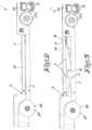
figure 2 to 8 show different height positions of the tube rail cart; -
figure 9 shows a frame with scissor lift and control device; -
figure 10 shows an alternative embodiment of the tube rail cart provided with leaf sliders; -
figure 11 shows an alternative embodiment of the tube rail cart provided with rose harvest bins; -
figure 12 shows a detail of a control device that is made partly transparent. - The tube rail cart 1 shown in
figure 1 comprises achassis 2 and ascissor lift 3 mounted thereon with a manually height-adjustable platform 4. - Said
platform 4 is adjustable between a lowered position with minimum height, as shown infigure 2 and an extended position with maximum height, as shown infigure 8 . - The tube rail cart 1 is provided with a lock for locking the
platform 4 in several height positions. - According to a special aspect of the invention, the lock comprises two locking mechanisms, a
first locking mechanism 5 and a second locking mechanism 6 respectively. - The
first locking mechanism 5 is used to lock theplatform 4 in an intermediary position. This is a position located between the lowered position and the extended position. - The second locking mechanism 6 serves as a lock of the
platform 4 in the extended position. - In this case, but not necessarily, the
platform 4 is also lockable using thefirst locking mechanism 5 in a position between the lowered position and the intermediary position, which is shown infigure 3 . -
Figures 5 to 7 show that in this case theplatform 4 is also lockable in different height positions between the intermediary position and the extended position and this using the second locking mechanism 6. - It is understood that both with the first and the second locking mechanism 6, more or fewer intermediate height positions could be developed and that there are not necessarily seven different height positions.
- In other words, it is thus not necessary either that, in the case of seven height positions like in the embodiment shown, the first three height positions are lockable with the
first locking mechanism 5 and the other four with the second locking mechanism 6. -
Figure 9 shows thescissor lift 3 and theframe 11 separately. Note in this case that thescissor lift 3 is formed by two pairs oflegs 7 which are each hingeably connected to each other around a centrally locatedpivotal point 8. - Two of the lower ends of the
scissor lift 3 are hingeably connected to thechassis 2 whereas the other two lower ends are provided with aroller guide 9 for moving on thechassis 2. - Note that the
aforementioned roller guide 9 can also be executed in other ways, for example as slider guide. - The
frame 11 is mounted freely hingedly on two of the upper ends of thelegs 7 of thescissor lift 3. In this case but not necessarily around the upper ends of thelegs 7 which are hingedly connected to thechassis 2. - The
scissor lift 3 is provided next to anelevation 10 of thechassis 2, which is clearly shown infigures 1 to 8 . - The
platform 4, which is executed as aflat panel 12, is mounted on top of theframe 11. - According to the invention, both the
first locking mechanism 5 and the second locking mechanism 6 are controlled by one and the same control device 13. - Said control device 13 is shown in
figure 9 together with thescissor lift 3 and theframe 11. The control device 13 comprises arod 14 whose thickenedend 15 is enclosed in ahandle 16. Said thickenedend 15 is provided with apeg 17 in the extension of therod 14. Over said peg 17 aspring 18 is mounted which is tensioned in achamber 19 of thehandle 16. - The
handle 16 is provided with twoslots 20 in which twobolts 21 of theframe 11 are slidably mounted. - Using the
slots 20, a rotational movement of thehandle 16 is transposed into a shift of thebolts 21 in theopenings 22. - The shift of the
bolts 21 in theopenings 22 ensures that theframe 11 is guided upward when thehandle 16 is rotated. - The end of the
rod 14, opposite to the end on which thehandle 16 is provided, can cooperate with one ormore holes 23 in theaforementioned elevation 10 of thechassis 2. In this way thefirst locking mechanism 5 is formed. - The
horizontal frame 11 is, in this case, but not necessarily, provided with fivegrooves 24. Saidgrooves 24 can cooperate with twobushings 25 provided on the upper ends of thelegs 7 which are hingedly connected to thechassis 2, to form the second locking mechanism 6. - In the bottom view of
figure 1 it is clearly shown that, in this case, but not necessarily, two gas springs 26 are used. - Said gas springs 26 prevent the
platform 4 from suddenly dropping when adjusting the height position and furthermore help to move theplatform 4 upward when it is unlocked. - The different views of
figure 1 also show that the tube rail cart 1 comprises fourflanged wheels 27, two of which on acommunal shaft 28 which is driven by anelectric motor 29. These are the driven flanged wheels 27A. The other twoflanged wheels 27 are so-calledidler wheels 30 and do not have a drive. - The shown
flanged wheels 27 areouter flange wheels 27, but inner flange wheels are also possible of course. Also note that the driven flanged wheels 27A could be provided with a separateelectric motor 29 and separate shaft. - Apart from the four
flanged wheels 27, twoswivel castors 31 can also be distinguished. These are mounted on a width-adjustable suspension 32. Saidadjustable suspension 32 is provided at the side of the tube rail cart 1 on which theidler wheels 30 are also mounted. - In fact, the
idler wheels 30 are located here between theswivel castors 31 and the driven flanged wheels 27A. - According to a special aspect of the invention, the
chassis 2 and/or theplatform 4 can also be provided with one ormore tubes 33 for mountingattachments 34 which are handy for harvesting crops, pruning activities and the like. -
Figure 10 shows different views of a tube rail cart 1 according to the invention with saidtubes 33 along both sides of theplatform 4 on each of which aleaf slider 35 is mounted in this case. This is particularly useful for pruning activities. Indeed, cut leaves are then guided down to the ground using theleaf slider 35, where they can be simply swept up. - An alternative embodiment is shown in
figure 12 . Here, saidtubes 33 are mounted on theplatform 4 and provided withrose harvest bins 36. Harvested roses can thus be simply stored in saidbins 36. - Note that both the
leaf sliders 35 and therose harvest bins 36 are height-adjustable along thetubes 33. This allows a worker to always set said tools to an ideal height. - In the case of the
rose harvest bins 36, apart from being height-adjustable, they are also tiltable and this in a very simple manner. - Furthermore, the
platform 4 can also be executed interchangeably depending on the functionalities mounted thereon that are required at that moment. - Furthermore, the
platform 4 can have pedals which control the drive of the tube rail cart 1. - The operation of the tube cart with height-
adjustable platform 4 is very simple and as follows. - The
platform 4 is, for example, locked on the intermediary position whereas the worker or user wants to set theplatform 4 one position lower. - To this end, the worker takes hold of the
handle 16 and executes a short rotational movement. The rotational movement is guided by theslots 20 in the thickenedend 15 of therod 14 and thehandle 16 and as a result of said rotational movement thespring 18 in thechamber 19 is tensioned further. Theslots 20 in the thickenedend 15 ensure that the rotational movement of thehandle 16 is transposed into an axial displacement of therod 14. - Consequently, the rotational movement ensures that the
rod 14 is pulled from ahole 23 of thechassis 2. Thefirst locking mechanism 5 is now unlocked and the platform can be moved upward and downward freely. - The worker holds the
handle 16 in said rotated position to prevent thehandle 16 from rotating back under the influence of thespring 18 such that therod 14 would move back in the opposite axial direction in the direction of thehole 23. - The assembly of
handle 16, thickenedend 15 of therod 14, thechamber 19 withpeg 17 andspring 18 are clearly shown infigure 11 , where thehandle 16 is shown in a transparent way. - As aforementioned the
platform 4 can now be moved upward and downward. The worker can realise this in a simple way with thehandle 16, by moving saidhandle 16 upward and downward. The platform will not drop abruptly and is furthermore simple to move upward and downward using the gas springs 26. - In this case, the worker moves the
platform 4 one position lower. When theplatform 4 is at the level of the desired position, the worker cancels the reverse rotational movement by rotating thehandle 16 in the opposite direction or by simply letting go of thehandle 16. Said opposite rotational movement is aided under the influence of the previously tensionedspring 18. - The
rod 14 now rotates back to its original resting position, such that therod 14 again undergoes an axial displacement, this time toward theelevation 10 of thechassis 2. The end of therod 14 now moves in ahole 23 that is subjacent to thehole 23 of the intermediary position. Theplatform 4 is locked again now, but this time in a lower position. The lock withrod 14 andhole 23 is the first locking mechanism as described above. - If the user subsequently wants to raise the
platform 4 to a height position that is higher than the intermediary position he or she rotates thehandle 16 again. Thefirst locking mechanism 5 unlocks theplatform 4 as above, after which the user lifts theplatform 4 to the desired height using thehandle 16. - For height positions above the intermediary position, there is no possibility to lock the
platform 4 with thefirst locking mechanism 5. Indeed, theelevation 10 of thechassis 2 is limited. Consequently, therod 14 can no longer be slid in ahole 23 of saidelevation 10. - To this end the tube rail cart 1 is provided with the second locking mechanism 6. The user unlocks the
platform 4 with a rotational movement of thehandle 16 and lifts theplatform 4 to the desired height position. - During the rotational movement of the
handle 16 not only the first but at the same time also the second locking mechanism 6 unlocks. This is because theslots 20 in thehandle 16 not only ensure an axial displacement of therod 14 but also a displacement of thebolts 21 according to the same direction as therod 14. The displacement of thebolts 21 guides theframe 11 upward via theopenings 22. - The user subsequently rotates the
handle 16 in the opposite direction or simply lets go of thehandle 16. Thespring 18, which is tensioned in thechamber 19, will move therod 14 and consequently also thebolts 21 back in the opposite direction. Theframe 11 subsequently is lowered onto thebushings 25 which are provided on thelegs 7. - Said
bushings 25 hook into thegrooves 24 of theframe 11 as it were such that theframe 11 is locked. To leave said height position again, rotating thehandle 16 such that theframe 11 is lifted a few centimetres again and thebushings 25 no longer hook into thegrooves 24, suffices. - Note that with the rotational movement of the
handle 16 both the first and the second locking mechanism 6 are always simultaneously unlocked. The height adjustment of theframe 11 is thus always with the same control device 13. - It is understood that both locking mechanisms are necessary. The
first locking mechanism 5 is necessary because at low height positions and thus small angles of thelegs 7, there is insufficient horizontal displacement. In other words, there is insufficient distance for providinggrooves 24 in theframe 11 at small angles between thelegs 7. - In turn, the second locking mechanism 6 is important as the
elevation 10 of thechassis 2 next to theplatform 4 is limited. With greater height positions there is thus nohole 23 in which therod 14 could ensure a lock. - It is understood that the invention is not limited to seven different height positions.
- The present invention is by no means limited to the embodiments described as an example and shown in the drawings, but a tube rail cart according to the invention can be realised in all kinds of forms and dimensions, without departing from the scope of the invention.
Claims (15)
- Tube rail cart comprising a chassis (2) and scissor lift (3) mounted thereon with a manually height-adjustable platform (4) between a lowered position with minimum height and an extended position with maximum height and which is provided with a lock for locking the platform (4) in several height positions, characterised in that the lock comprises two different locking mechanisms, respectively a first locking mechanism (5) for locking the platform (4) in an intermediary position between the lowered position and the extended position and a second locking mechanism (6) for locking the platform (4) in the extended position.
- Tube rail cart according to claim 1, characterised in that the platform (4) is lockable in one or more height positions between the intermediary position and the lowered position using the first locking mechanism (5).
- Tube rail cart according to claim 1 or 2, characterised in that the platform (4) is lockable in one or more height positions between the intermediary position and the extended position using the second locking mechanism (6).
- Tube rail cart according to any one of the previous claims, characterised in that the first and the second locking mechanism (6) are controlled by one and the same control device (13).
- Tube rail cart according to any one of the previous claims, characterised in that the number of different height positions, preferably is located between two and fifteen, ideally the platform can be locked in seven different height positions.
- Tube rail cart according to claim 5, characterised in that in the case of seven different height positions, the first three height positions, starting with the lowered position, are lockable with the first locking mechanism (5) and that the other four height positions are lockable with the second locking mechanism (6).
- Tube rail cart according to any one of the previous claims, characterised in that the scissor lift (3) is formed by two pairs of legs (7) which are each hingeably connected to each other around a centrally located pivotal point (8) and whereby two of the lower ends of the scissor lift (3) are hingeably connected to the chassis (2) whereas the two other lower ends are provided with a slider or roller guide (9) for moving on the chassis (2) and whereby the platform (4) is mounted freely hingeably on two of the upper ends of the legs (7).
- Tube rail cart according to any one of the previous claims, characterised in that the platform (4) is hingeable around the upper ends of the legs (7) which are hingeably connected to the chassis (2).
- Tube rail cart according to any one of the previous claims, characterised in that the scissor lift (3) is provided next to an elevation (10) of the chassis (2).
- Tube rail cart according to any one of the previous claims 4 to 9, characterised in that the control device (13) comprises a rod (14) whose thickened end (15) is enclosed in a rotatable handle (16), whereby said thickened end (15) in the extension of the rod (14) is provided with a peg (17) over which a spring (18) is mounted which is tensioned in a chamber (19) of the handle (16) of the rod (14) and whereby the rotational movement of the handle (16) and the thickened end (15) of the rod (14) are guided by one or more slots (20) in the handle (16) and the thickened end (15) which cooperate with one or more bolts (21) which can move upward and downward in openings (22) of the frame (11) provided to this end.
- Tube rail cart according to any one of the previous claims, characterised in that the end of the rod (14), opposite to the end on which the handle (16) is provided, can cooperate with one or more holes (23) in the elevation (10) of the chassis (2) to form the first locking mechanism (5) .
- Tube rail cart according to any one of the previous claims, characterised in that the frame (11) is provided with one or more grooves (24) which can cooperate with one or more bushings (25) which are provided on the upper ends of the legs (7) of the scissor lift (3) to form the second locking mechanism (6).
- Tube rail cart according to any one of the previous claims, characterised in that the scissor lift (3) is provided with one or more gas springs (26) to help raise the platform (4) or to prevent said platform (4) from suddenly dropping when adjusting the height position.
- Tube rail cart according to any one of the previous claims, characterised in that the tube rail cart (1) comprises four flanged wheels (27), of which two driven wheels and two idler wheels (30) and whereby two swivel castors (31) are provided on a width-adjustable suspension (32) which is located on the side of the idler wheels (30).
- Tube rail cart according to any one of the previous claims, characterised in that the chassis (2) and/or the platform (4) is/are provided with one or more tubes (33) for mounting attachments (34) which are necessary for harvesting crops, pruning activities and the like, such as one or several leaf sliders (35).
Applications Claiming Priority (1)
| Application Number | Priority Date | Filing Date | Title |
|---|---|---|---|
| BE20225183A BE1030352B1 (en) | 2022-03-16 | 2022-03-16 | Pipe rail trolley |
Publications (2)
| Publication Number | Publication Date |
|---|---|
| EP4245119A1 true EP4245119A1 (en) | 2023-09-20 |
| EP4245119B1 EP4245119B1 (en) | 2024-06-05 |
Family
ID=80999731
Family Applications (1)
| Application Number | Title | Priority Date | Filing Date |
|---|---|---|---|
| EP23159960.6A Active EP4245119B1 (en) | 2022-03-16 | 2023-03-03 | Tube rail cart |
Country Status (3)
| Country | Link |
|---|---|
| EP (1) | EP4245119B1 (en) |
| BE (1) | BE1030352B1 (en) |
| PL (1) | PL4245119T3 (en) |
Citations (4)
| Publication number | Priority date | Publication date | Assignee | Title |
|---|---|---|---|---|
| CN209635845U (en) | 2019-02-20 | 2019-11-15 | 温州科技职业学院 | A kind of multi-functional greenhouse job platform that do not derail |
| CN111115500A (en) | 2019-12-31 | 2020-05-08 | 嘉兴职业技术学院 | Self-locking mechanism for lift |
| CN210519478U (en) | 2019-09-16 | 2020-05-15 | 高金龙 | Lifting platform for pruning and picking fruits of fruit growers |
| CN113212479A (en) | 2021-05-28 | 2021-08-06 | 中国农业大学 | Multifunctional electric track operation platform for greenhouse |
-
2022
- 2022-03-16 BE BE20225183A patent/BE1030352B1/en not_active IP Right Cessation
-
2023
- 2023-03-03 PL PL23159960.6T patent/PL4245119T3/en unknown
- 2023-03-03 EP EP23159960.6A patent/EP4245119B1/en active Active
Patent Citations (4)
| Publication number | Priority date | Publication date | Assignee | Title |
|---|---|---|---|---|
| CN209635845U (en) | 2019-02-20 | 2019-11-15 | 温州科技职业学院 | A kind of multi-functional greenhouse job platform that do not derail |
| CN210519478U (en) | 2019-09-16 | 2020-05-15 | 高金龙 | Lifting platform for pruning and picking fruits of fruit growers |
| CN111115500A (en) | 2019-12-31 | 2020-05-08 | 嘉兴职业技术学院 | Self-locking mechanism for lift |
| CN113212479A (en) | 2021-05-28 | 2021-08-06 | 中国农业大学 | Multifunctional electric track operation platform for greenhouse |
Also Published As
| Publication number | Publication date |
|---|---|
| BE1030352B1 (en) | 2023-10-17 |
| EP4245119B1 (en) | 2024-06-05 |
| PL4245119T3 (en) | 2024-09-30 |
| BE1030352A1 (en) | 2023-10-10 |
Similar Documents
| Publication | Publication Date | Title |
|---|---|---|
| US2882977A (en) | Gardening machine | |
| EP3259982B1 (en) | Tube rail cart | |
| KR20170055027A (en) | Electric vehicle for harvesting fruits and vegetables | |
| CN112449903A (en) | Automatic trimming means of greenbelt is used in gardens | |
| EP4245119B1 (en) | Tube rail cart | |
| DE3838703A1 (en) | Mobile retaining apparatus for hand tools | |
| US6715272B2 (en) | Device and method for supporting a self-powered hedge cutter | |
| US3338314A (en) | Edger and trimmer | |
| KR101809610B1 (en) | tea plantation cultivator | |
| EP0044602A1 (en) | Raising device | |
| EP3741203B1 (en) | Device for growing mushrooms | |
| NL2027977B1 (en) | Horticulture trolley with upright operator support posts forming part of integrated linear guidance systems for standing plateaus. | |
| KR101621344B1 (en) | Shiitake growing device | |
| CN112616464A (en) | Device capable of cutting multiple cuttage branches at one time | |
| JP2007060935A (en) | Apparatus for tea field husbandry | |
| CN113802696A (en) | Mobile trellis for horticultural planting modular workbench | |
| CN108584811B (en) | A garden pruning tool | |
| CN223730347U (en) | Forestry branch trimming means with adjustable | |
| CN221228306U (en) | Handcart for trimming hedges | |
| KR101493153B1 (en) | Vehicle for farm work | |
| CN220292621U (en) | Afforestation trimming machine | |
| WO2008140329A1 (en) | Improvements in fruit harvesting equipment | |
| KR100845177B1 (en) | Loading box drive for agricultural machinery | |
| CN220342941U (en) | Afforestation trimming machine | |
| CN220986768U (en) | Special pruning tool for landscaping |
Legal Events
| Date | Code | Title | Description |
|---|---|---|---|
| PUAI | Public reference made under article 153(3) epc to a published international application that has entered the european phase |
Free format text: ORIGINAL CODE: 0009012 |
|
| STAA | Information on the status of an ep patent application or granted ep patent |
Free format text: STATUS: THE APPLICATION HAS BEEN PUBLISHED |
|
| AK | Designated contracting states |
Kind code of ref document: A1 Designated state(s): AL AT BE BG CH CY CZ DE DK EE ES FI FR GB GR HR HU IE IS IT LI LT LU LV MC ME MK MT NL NO PL PT RO RS SE SI SK SM TR |
|
| STAA | Information on the status of an ep patent application or granted ep patent |
Free format text: STATUS: REQUEST FOR EXAMINATION WAS MADE |
|
| 17P | Request for examination filed |
Effective date: 20230928 |
|
| RBV | Designated contracting states (corrected) |
Designated state(s): AL AT BE BG CH CY CZ DE DK EE ES FI FR GB GR HR HU IE IS IT LI LT LU LV MC ME MK MT NL NO PL PT RO RS SE SI SK SM TR |
|
| GRAP | Despatch of communication of intention to grant a patent |
Free format text: ORIGINAL CODE: EPIDOSNIGR1 |
|
| STAA | Information on the status of an ep patent application or granted ep patent |
Free format text: STATUS: GRANT OF PATENT IS INTENDED |
|
| RIC1 | Information provided on ipc code assigned before grant |
Ipc: F16M 11/42 20060101ALI20240201BHEP Ipc: F16M 11/38 20060101ALI20240201BHEP Ipc: F16M 11/22 20060101ALI20240201BHEP Ipc: F16M 11/18 20060101ALI20240201BHEP Ipc: F16M 11/04 20060101ALI20240201BHEP Ipc: B66F 11/04 20060101ALI20240201BHEP Ipc: B66F 7/06 20060101ALI20240201BHEP Ipc: B61D 15/00 20060101ALI20240201BHEP Ipc: B61D 3/04 20060101ALI20240201BHEP Ipc: A01D 46/20 20060101ALI20240201BHEP Ipc: A01D 45/00 20180101AFI20240201BHEP |
|
| INTG | Intention to grant announced |
Effective date: 20240216 |
|
| GRAS | Grant fee paid |
Free format text: ORIGINAL CODE: EPIDOSNIGR3 |
|
| GRAA | (expected) grant |
Free format text: ORIGINAL CODE: 0009210 |
|
| STAA | Information on the status of an ep patent application or granted ep patent |
Free format text: STATUS: THE PATENT HAS BEEN GRANTED |
|
| AK | Designated contracting states |
Kind code of ref document: B1 Designated state(s): AL AT BE BG CH CY CZ DE DK EE ES FI FR GB GR HR HU IE IS IT LI LT LU LV MC ME MK MT NL NO PL PT RO RS SE SI SK SM TR |
|
| REG | Reference to a national code |
Ref country code: CH Ref legal event code: EP |
|
| REG | Reference to a national code |
Ref country code: DE Ref legal event code: R096 Ref document number: 602023000129 Country of ref document: DE |
|
| REG | Reference to a national code |
Ref country code: IE Ref legal event code: FG4D |
|
| REG | Reference to a national code |
Ref country code: NL Ref legal event code: FP |
|
| RAP4 | Party data changed (patent owner data changed or rights of a patent transferred) |
Owner name: BOGAERTS NEXT ENGINEERING BV |
|
| REG | Reference to a national code |
Ref country code: LT Ref legal event code: MG9D |
|
| PG25 | Lapsed in a contracting state [announced via postgrant information from national office to epo] |
Ref country code: BG Free format text: LAPSE BECAUSE OF FAILURE TO SUBMIT A TRANSLATION OF THE DESCRIPTION OR TO PAY THE FEE WITHIN THE PRESCRIBED TIME-LIMIT Effective date: 20240605 |
|
| PG25 | Lapsed in a contracting state [announced via postgrant information from national office to epo] |
Ref country code: FI Free format text: LAPSE BECAUSE OF FAILURE TO SUBMIT A TRANSLATION OF THE DESCRIPTION OR TO PAY THE FEE WITHIN THE PRESCRIBED TIME-LIMIT Effective date: 20240605 Ref country code: HR Free format text: LAPSE BECAUSE OF FAILURE TO SUBMIT A TRANSLATION OF THE DESCRIPTION OR TO PAY THE FEE WITHIN THE PRESCRIBED TIME-LIMIT Effective date: 20240605 |
|
| PG25 | Lapsed in a contracting state [announced via postgrant information from national office to epo] |
Ref country code: GR Free format text: LAPSE BECAUSE OF FAILURE TO SUBMIT A TRANSLATION OF THE DESCRIPTION OR TO PAY THE FEE WITHIN THE PRESCRIBED TIME-LIMIT Effective date: 20240906 |
|
| PG25 | Lapsed in a contracting state [announced via postgrant information from national office to epo] |
Ref country code: ES Free format text: LAPSE BECAUSE OF FAILURE TO SUBMIT A TRANSLATION OF THE DESCRIPTION OR TO PAY THE FEE WITHIN THE PRESCRIBED TIME-LIMIT Effective date: 20240605 |
|
| PG25 | Lapsed in a contracting state [announced via postgrant information from national office to epo] |
Ref country code: LV Free format text: LAPSE BECAUSE OF FAILURE TO SUBMIT A TRANSLATION OF THE DESCRIPTION OR TO PAY THE FEE WITHIN THE PRESCRIBED TIME-LIMIT Effective date: 20240605 |
|
| PG25 | Lapsed in a contracting state [announced via postgrant information from national office to epo] |
Ref country code: NO Free format text: LAPSE BECAUSE OF FAILURE TO SUBMIT A TRANSLATION OF THE DESCRIPTION OR TO PAY THE FEE WITHIN THE PRESCRIBED TIME-LIMIT Effective date: 20240905 Ref country code: LV Free format text: LAPSE BECAUSE OF FAILURE TO SUBMIT A TRANSLATION OF THE DESCRIPTION OR TO PAY THE FEE WITHIN THE PRESCRIBED TIME-LIMIT Effective date: 20240605 Ref country code: HR Free format text: LAPSE BECAUSE OF FAILURE TO SUBMIT A TRANSLATION OF THE DESCRIPTION OR TO PAY THE FEE WITHIN THE PRESCRIBED TIME-LIMIT Effective date: 20240605 Ref country code: GR Free format text: LAPSE BECAUSE OF FAILURE TO SUBMIT A TRANSLATION OF THE DESCRIPTION OR TO PAY THE FEE WITHIN THE PRESCRIBED TIME-LIMIT Effective date: 20240906 Ref country code: FI Free format text: LAPSE BECAUSE OF FAILURE TO SUBMIT A TRANSLATION OF THE DESCRIPTION OR TO PAY THE FEE WITHIN THE PRESCRIBED TIME-LIMIT Effective date: 20240605 Ref country code: ES Free format text: LAPSE BECAUSE OF FAILURE TO SUBMIT A TRANSLATION OF THE DESCRIPTION OR TO PAY THE FEE WITHIN THE PRESCRIBED TIME-LIMIT Effective date: 20240605 Ref country code: BG Free format text: LAPSE BECAUSE OF FAILURE TO SUBMIT A TRANSLATION OF THE DESCRIPTION OR TO PAY THE FEE WITHIN THE PRESCRIBED TIME-LIMIT Effective date: 20240605 Ref country code: RS Free format text: LAPSE BECAUSE OF FAILURE TO SUBMIT A TRANSLATION OF THE DESCRIPTION OR TO PAY THE FEE WITHIN THE PRESCRIBED TIME-LIMIT Effective date: 20240905 |
|
| REG | Reference to a national code |
Ref country code: AT Ref legal event code: MK05 Ref document number: 1691715 Country of ref document: AT Kind code of ref document: T Effective date: 20240605 |
|
| PG25 | Lapsed in a contracting state [announced via postgrant information from national office to epo] |
Ref country code: PT Free format text: LAPSE BECAUSE OF FAILURE TO SUBMIT A TRANSLATION OF THE DESCRIPTION OR TO PAY THE FEE WITHIN THE PRESCRIBED TIME-LIMIT Effective date: 20241007 |
|
| PG25 | Lapsed in a contracting state [announced via postgrant information from national office to epo] |
Ref country code: PT Free format text: LAPSE BECAUSE OF FAILURE TO SUBMIT A TRANSLATION OF THE DESCRIPTION OR TO PAY THE FEE WITHIN THE PRESCRIBED TIME-LIMIT Effective date: 20241007 |
|
| PG25 | Lapsed in a contracting state [announced via postgrant information from national office to epo] |
Ref country code: EE Free format text: LAPSE BECAUSE OF FAILURE TO SUBMIT A TRANSLATION OF THE DESCRIPTION OR TO PAY THE FEE WITHIN THE PRESCRIBED TIME-LIMIT Effective date: 20240605 |
|
| PG25 | Lapsed in a contracting state [announced via postgrant information from national office to epo] |
Ref country code: AT Free format text: LAPSE BECAUSE OF FAILURE TO SUBMIT A TRANSLATION OF THE DESCRIPTION OR TO PAY THE FEE WITHIN THE PRESCRIBED TIME-LIMIT Effective date: 20240605 Ref country code: IS Free format text: LAPSE BECAUSE OF FAILURE TO SUBMIT A TRANSLATION OF THE DESCRIPTION OR TO PAY THE FEE WITHIN THE PRESCRIBED TIME-LIMIT Effective date: 20241005 |
|
| PG25 | Lapsed in a contracting state [announced via postgrant information from national office to epo] |
Ref country code: CZ Free format text: LAPSE BECAUSE OF FAILURE TO SUBMIT A TRANSLATION OF THE DESCRIPTION OR TO PAY THE FEE WITHIN THE PRESCRIBED TIME-LIMIT Effective date: 20240605 |
|
| PG25 | Lapsed in a contracting state [announced via postgrant information from national office to epo] |
Ref country code: RO Free format text: LAPSE BECAUSE OF FAILURE TO SUBMIT A TRANSLATION OF THE DESCRIPTION OR TO PAY THE FEE WITHIN THE PRESCRIBED TIME-LIMIT Effective date: 20240605 Ref country code: SK Free format text: LAPSE BECAUSE OF FAILURE TO SUBMIT A TRANSLATION OF THE DESCRIPTION OR TO PAY THE FEE WITHIN THE PRESCRIBED TIME-LIMIT Effective date: 20240605 |
|
| PG25 | Lapsed in a contracting state [announced via postgrant information from national office to epo] |
Ref country code: SM Free format text: LAPSE BECAUSE OF FAILURE TO SUBMIT A TRANSLATION OF THE DESCRIPTION OR TO PAY THE FEE WITHIN THE PRESCRIBED TIME-LIMIT Effective date: 20240605 |
|
| PG25 | Lapsed in a contracting state [announced via postgrant information from national office to epo] |
Ref country code: SM Free format text: LAPSE BECAUSE OF FAILURE TO SUBMIT A TRANSLATION OF THE DESCRIPTION OR TO PAY THE FEE WITHIN THE PRESCRIBED TIME-LIMIT Effective date: 20240605 Ref country code: SK Free format text: LAPSE BECAUSE OF FAILURE TO SUBMIT A TRANSLATION OF THE DESCRIPTION OR TO PAY THE FEE WITHIN THE PRESCRIBED TIME-LIMIT Effective date: 20240605 Ref country code: RO Free format text: LAPSE BECAUSE OF FAILURE TO SUBMIT A TRANSLATION OF THE DESCRIPTION OR TO PAY THE FEE WITHIN THE PRESCRIBED TIME-LIMIT Effective date: 20240605 Ref country code: IS Free format text: LAPSE BECAUSE OF FAILURE TO SUBMIT A TRANSLATION OF THE DESCRIPTION OR TO PAY THE FEE WITHIN THE PRESCRIBED TIME-LIMIT Effective date: 20241005 Ref country code: EE Free format text: LAPSE BECAUSE OF FAILURE TO SUBMIT A TRANSLATION OF THE DESCRIPTION OR TO PAY THE FEE WITHIN THE PRESCRIBED TIME-LIMIT Effective date: 20240605 Ref country code: CZ Free format text: LAPSE BECAUSE OF FAILURE TO SUBMIT A TRANSLATION OF THE DESCRIPTION OR TO PAY THE FEE WITHIN THE PRESCRIBED TIME-LIMIT Effective date: 20240605 Ref country code: AT Free format text: LAPSE BECAUSE OF FAILURE TO SUBMIT A TRANSLATION OF THE DESCRIPTION OR TO PAY THE FEE WITHIN THE PRESCRIBED TIME-LIMIT Effective date: 20240605 |
|
| PG25 | Lapsed in a contracting state [announced via postgrant information from national office to epo] |
Ref country code: IT Free format text: LAPSE BECAUSE OF FAILURE TO SUBMIT A TRANSLATION OF THE DESCRIPTION OR TO PAY THE FEE WITHIN THE PRESCRIBED TIME-LIMIT Effective date: 20240605 |
|
| REG | Reference to a national code |
Ref country code: DE Ref legal event code: R097 Ref document number: 602023000129 Country of ref document: DE |
|
| PLBE | No opposition filed within time limit |
Free format text: ORIGINAL CODE: 0009261 |
|
| STAA | Information on the status of an ep patent application or granted ep patent |
Free format text: STATUS: NO OPPOSITION FILED WITHIN TIME LIMIT |
|
| PG25 | Lapsed in a contracting state [announced via postgrant information from national office to epo] |
Ref country code: DK Free format text: LAPSE BECAUSE OF FAILURE TO SUBMIT A TRANSLATION OF THE DESCRIPTION OR TO PAY THE FEE WITHIN THE PRESCRIBED TIME-LIMIT Effective date: 20240605 |
|
| 26N | No opposition filed |
Effective date: 20250306 |
|
| PG25 | Lapsed in a contracting state [announced via postgrant information from national office to epo] |
Ref country code: SE Free format text: LAPSE BECAUSE OF FAILURE TO SUBMIT A TRANSLATION OF THE DESCRIPTION OR TO PAY THE FEE WITHIN THE PRESCRIBED TIME-LIMIT Effective date: 20240605 |
|
| REG | Reference to a national code |
Ref country code: DE Ref legal event code: R119 Ref document number: 602023000129 Country of ref document: DE |
|
| PG25 | Lapsed in a contracting state [announced via postgrant information from national office to epo] |
Ref country code: MC Free format text: LAPSE BECAUSE OF FAILURE TO SUBMIT A TRANSLATION OF THE DESCRIPTION OR TO PAY THE FEE WITHIN THE PRESCRIBED TIME-LIMIT Effective date: 20240605 |
|
| PG25 | Lapsed in a contracting state [announced via postgrant information from national office to epo] |
Ref country code: LU Free format text: LAPSE BECAUSE OF NON-PAYMENT OF DUE FEES Effective date: 20250303 |
|
| PG25 | Lapsed in a contracting state [announced via postgrant information from national office to epo] |
Ref country code: DE Free format text: LAPSE BECAUSE OF NON-PAYMENT OF DUE FEES Effective date: 20251001 |
|
| PG25 | Lapsed in a contracting state [announced via postgrant information from national office to epo] |
Ref country code: FR Free format text: LAPSE BECAUSE OF NON-PAYMENT OF DUE FEES Effective date: 20250331 |
|
| PG25 | Lapsed in a contracting state [announced via postgrant information from national office to epo] |
Ref country code: IE Free format text: LAPSE BECAUSE OF NON-PAYMENT OF DUE FEES Effective date: 20250303 |
|
| PGFP | Annual fee paid to national office [announced via postgrant information from national office to epo] |
Ref country code: BE Payment date: 20260323 Year of fee payment: 4 |
|
| PGFP | Annual fee paid to national office [announced via postgrant information from national office to epo] |
Ref country code: NL Payment date: 20260323 Year of fee payment: 4 |
|
| PGFP | Annual fee paid to national office [announced via postgrant information from national office to epo] |
Ref country code: PL Payment date: 20260223 Year of fee payment: 4 |
|
| PG25 | Lapsed in a contracting state [announced via postgrant information from national office to epo] |
Ref country code: CY Free format text: LAPSE BECAUSE OF FAILURE TO SUBMIT A TRANSLATION OF THE DESCRIPTION OR TO PAY THE FEE WITHIN THE PRESCRIBED TIME-LIMIT Effective date: 20240605 |
|
| PG25 | Lapsed in a contracting state [announced via postgrant information from national office to epo] |
Ref country code: LT Free format text: LAPSE BECAUSE OF FAILURE TO SUBMIT A TRANSLATION OF THE DESCRIPTION OR TO PAY THE FEE WITHIN THE PRESCRIBED TIME-LIMIT Effective date: 20240605 |
|
| PG25 | Lapsed in a contracting state [announced via postgrant information from national office to epo] |
Ref country code: TR Free format text: LAPSE BECAUSE OF FAILURE TO SUBMIT A TRANSLATION OF THE DESCRIPTION OR TO PAY THE FEE WITHIN THE PRESCRIBED TIME-LIMIT Effective date: 20240605 |