EP4244960B1 - Verfahren zum einbau einer axialflussmaschine - Google Patents
Verfahren zum einbau einer axialflussmaschine Download PDFInfo
- Publication number
- EP4244960B1 EP4244960B1 EP21823723.8A EP21823723A EP4244960B1 EP 4244960 B1 EP4244960 B1 EP 4244960B1 EP 21823723 A EP21823723 A EP 21823723A EP 4244960 B1 EP4244960 B1 EP 4244960B1
- Authority
- EP
- European Patent Office
- Prior art keywords
- rotor
- stator
- motor housing
- axial flux
- flux machine
- Prior art date
- Legal status (The legal status is an assumption and is not a legal conclusion. Google has not performed a legal analysis and makes no representation as to the accuracy of the status listed.)
- Active
Links
Images




Classifications
-
- H—ELECTRICITY
- H02—GENERATION; CONVERSION OR DISTRIBUTION OF ELECTRIC POWER
- H02K—DYNAMO-ELECTRIC MACHINES
- H02K15/00—Processes or apparatus specially adapted for manufacturing, assembling, maintaining or repairing of dynamo-electric machines
-
- H—ELECTRICITY
- H02—GENERATION; CONVERSION OR DISTRIBUTION OF ELECTRIC POWER
- H02K—DYNAMO-ELECTRIC MACHINES
- H02K15/00—Processes or apparatus specially adapted for manufacturing, assembling, maintaining or repairing of dynamo-electric machines
- H02K15/06—Embedding prefabricated windings in the machines
- H02K15/061—Air-gap windings
-
- H—ELECTRICITY
- H02—GENERATION; CONVERSION OR DISTRIBUTION OF ELECTRIC POWER
- H02K—DYNAMO-ELECTRIC MACHINES
- H02K21/00—Synchronous motors having permanent magnets; Synchronous generators having permanent magnets
- H02K21/12—Synchronous motors having permanent magnets; Synchronous generators having permanent magnets with stationary armatures and rotating magnets
- H02K21/24—Synchronous motors having permanent magnets; Synchronous generators having permanent magnets with stationary armatures and rotating magnets with magnets axially facing the armatures, e.g. hub-type cycle dynamos
Definitions
- the invention relates to a method for installing an axial flux machine with at least two active parts in a motor housing, of which a first active part is designed as a rotor with a number of permanent magnets and a second active part is designed as a stator with a number of electrical windings, wherein the rotor and the stator are arranged adjacent to one another and secured against rotation in a transport configuration in a space-saving package formed by the magnetic attraction forces of the permanent magnets, in particular in a stack.
- Axial flux machines usually have at least two active parts.
- one or more stators can be provided for a disk-shaped rotor.
- the rotor is usually equipped with one or more permanent magnets.
- the permanent magnet can also be made in one piece, whereby several poles can be formed, for example, by magnetization.
- An air gap is provided between the rotor and the stator.
- the stator has corresponding poles with coil windings, which, when energized, create a suitable magnetic field. The interaction between the magnetic field of the stator and the magnetic field of the rotor moves the rotor and transmits a torque to a rotor shaft.
- a frameless torque motor with a transport lock is known.
- a transport lock is provided as a spacer between a primary and a secondary part.
- a method for installing an axial flow machine with at least two active parts in a motor housing, of which a first active part is designed as a rotor with a number of permanent magnets and a second active part as a stator with a number of electrical windings, wherein the rotor and the stator are arranged adjacent to one another and secured against rotation in a transport configuration in a space-saving package formed by the magnetic attraction forces of the permanent magnets, in particular in a stack, wherein the rotor and the stator are arranged immediately adjacent to one another in the transport configuration so that at least in partial areas of the rotor, the rotor touches the adjacent stator without play and without an air gap and the package is subsequently introduced into the motor housing and positioned in the motor housing in such a way that thereafter, on the one hand, by means of a first mechanical axial stop arranged on the motor housing, in particular in the direction of the rotor shaft, for at least one of the at least two active parts and on the
- active parts are all those parts of the axial flux machine that are active in the sense of generating and guiding a magnetic field. These include rotors, stators and other electrically/magnetically active parts, for example components for the magnetic return path.
- pre-assembly of the active parts is carried out in such a way that the components are stacked without an air gap. This largely shields the magnetic field of the magnets and there is no longer any long-range effect of the magnetic field. This makes handling during transport and assembly much easier.
- the air gaps are then automatically adjusted according to one embodiment of the invention. Separate handling of the components is not necessary.
- Another advantage according to one embodiment of the invention is that such pre-assembly can be subjected to a so-called end-of-line (EOL) test and, in addition to functional tests, the installation process itself can also be simulated at the customer's site.
- EOL end-of-line
- the rotor is arranged in a positionally secure manner, in particular rotationally secure and/or displacement-proof in the package, due to the magnetic attraction forces between the permanent magnets of the rotor and the magnetic material in the other active parts.
- rotationally secure is defined as an arrangement in which the rotor is prevented from rotating relative to the other active parts by the other components.
- the magnetic attraction creates at least a partial force connection, in particular through the effect of friction, between the active parts.
- the method according to the invention makes it possible to reduce the occurrence of stray fields on the rotor and, due to the direct contact of the active parts, contamination of the rotor on the contact surfaces can be significantly reduced or prevented.
- the stator and/or the rotor can be at least partially overmolded with a plastic and/or a thermoplastic material.
- a plastic and/or a thermoplastic material Such an overmold is integrally connected and remains attached to the active part even during operation.
- the surface of the contacting active parts has a certain unevenness or roughness. For this reason, such contact between the active parts will never be completely flat. Furthermore, it can be provided that the surface of the active parts has a predetermined geometric shape, for example conical surface portions, and/or structure, for example with protruding ribs. In such a case, the contact is established via this structure or its elements, in particular the ribs.
- the rotor and the stator in the transport configuration are in contact with each other over a proportion of at least 20%, at least 50% or at least 80% of the opposing surface areas in the package without an air gap.
- no spacers are arranged between the active parts which contact each other without play.
- the at least two active parts of the axial flow machine are telescopically moved apart from one another during installation and/or assembly in the motor housing, starting from the package-like transport configuration.
- the air gaps between the rotor(s) and the other active parts, which are essential for the operation of the axial flow machine, are set.
- the installation space of the motor housing for positioning the axial flow machine is pot-shaped and the package of at least two active parts in the transport configuration is introduced from a first side into the thus formed at least partially hollow installation space of the motor so that at least the area of contact between stator and rotor is laterally covered by the motor housing.
- At least one of the at least two active parts of the axial flow machine is fastened in the motor housing via the first tension and/or compression element. According to a particular embodiment, the invention thus enables the fastening and/or positioning of all active parts in one operation.
- the first tension and/or compression element is designed as part of a screw connection.
- the stator is positioned in the installation space of the motor housing via the first stop.
- the first tension and/or compression element increases the distance between the rotor and the stator by exerting a tension and/or compression force on the rotor from the side of the motor housing opposite the side where the package is inserted into the motor housing, thereby setting the at least one air gap between the stator and the rotor required for the operation of the axial flow machine.
- the at least two active parts have a return element as a further active element, which is arranged in the package of the transport configuration on the side of the rotor opposite the stator.
- the return element is removed from the rotor by the first tension and/or pressure element and/or a further tension and/or pressure element, whereby a further air gap of the at least one air gap required for the operation of the axial flow machine is set in this case between the rotor and the return element.
- the invention is further characterized by a transport configuration of the active parts of an axial flow machine for use in a method according to one of the preceding claims 1 to 6.
- the invention is further characterized by an axial flow machine in a motor housing, which is installed in the motor housing by a method according to one of claims 1 to 6.
- the active parts in the transport configuration are arranged in the order of installation and/or assembly handling.
- This measure makes the installation of the active parts particularly efficient and time-saving.
- a rotor shaft is provided.
- the package of active parts is already arranged on the rotor shaft in the transport configuration.
- a mechanical stop is provided on a first of the at least two active parts, which can interact with a mechanical stop in the motor housing in order to define the installation position of the first active part in the motor housing.
- a rotor shaft is provided and is exerted via the tension/compression element in interaction with the mechanical stop in the motor housing when the package is installed in the motor housing via a tensile or compressive force which acts against the magnetic attraction forces of the permanent magnets in the direction of the axis of the rotor shaft, so that one or more air gaps are formed, in particular on the rotor.
- the tension/compression element has an adjusting mechanism, preferably with a thread.
- the and/or the air gaps can be adjusted by the adjusting mechanism.
- the first active part is designed as a stator
- the second active part as a rotor
- a third active part is provided as a return part for realizing the magnetic return.
- the invention is characterized by an axial flux machine with a first active part, which is designed as a stator and a second active part, which is designed as a rotor with a number of permanent magnets and a third active part, which is designed as a return part.
- the active parts are arranged adjacent to one another, in particular adjacent, in a transport configuration in a space-saving package formed by the magnetic attraction forces of the permanent magnets, in particular in a stack, such that the rotor is arranged between the stator and the return part, preferably in a rotationally secure manner by the magnetic attraction forces of the permanent magnets of the rotor.
- the invention is characterized in that a mechanical stop is provided on the stator, which interacts with an axial stop surface in the motor housing and the return part also has an axial stop surface, which interacts with a further axial stop surface in the motor housing.
- a tension/pressure element for example a screw connection, is used to create an adjustment mechanism, via which, for example with a thread on the return part during assembly in the engine housing, the tension and/or pressure force exerted by the tension/pressure element of the rotor can be removed in the axial direction so that an air gap can be set between the rotor and the return part.
- a further air gap is created between the stator and the rotor so that the rotor can be rotated in the motor housing when mounted.
- a rotor shaft is provided and the package of active parts is already arranged on the rotor shaft in the transport configuration.
- an axial flux machine is provided with a first active part, which is designed as a first stator and a second active part, which is designed as a rotor with a number of permanent magnets and with a third active part, which is designed as a second stator.
- the active parts are arranged adjacent to one another, in particular adjacent, in a transport configuration in a space-saving package formed by the magnetic attraction forces of the permanent magnets, in particular in a stack, such that the rotor is arranged between the first and second stators, preferably in a rotationally secure manner by the magnetic attraction forces of the permanent magnets.
- a mechanical stop is provided in the motor housing for both the first and the second stator.
- a tension and/or compression element for example a screw connection, is provided, whereby the second stator can be removed from the rotor during assembly with the tension and/or compression force exerted by the tension and/or compression element, so that an air gap is established between the first stator and the rotor on the one hand and the rotor and the second stator on the other hand and the rotor can be rotated in the motor housing in the assembled state.
- an axial flow machine is provided with a first active part, which is designed as a stator, and a second active part, which is designed as a rotor with a number of permanent magnets, wherein the two active parts are arranged adjacent to one another, in particular adjacent to one another in a transport configuration in a space-saving package formed by the magnetic attraction forces of the permanent magnets, in particular in a stack, such that the rotor is preferably connected to the stator in a rotationally secure manner by the magnetic attraction forces and a rotor shaft is provided on which the rotor is arranged.
- the invention is characterized in that a mechanical, in particular axial, stop is provided in the motor housing, which interacts with the rotor shaft, so that, for example, in particular a bearing of the rotor shaft is positioned via the stop.
- a tension and/or compression element in particular with a An adjusting mechanism, for example a thread, is provided, whereby the stator, when mounted in the motor housing, can be removed axially from the rotor with a tensile force of the tensile and/or compressive element, against the attractive forces of the permanent magnets and against the stop or stops, in particular in the direction of the rotor shaft axis, so that an air gap is established between the stator and the rotor and the rotor can be rotated in the motor housing when mounted.
- the invention is characterized by a method for installing an axial flux machine, wherein the active parts of the axial flux machine are transported adjacent to one another, in particular adjacent, in a transport configuration in a space-saving package, in particular in a stack, formed by the magnetic attraction forces of the permanent magnets, wherein the rotor is arranged in the package of active parts, preferably in a rotationally secure manner, by the magnetic attraction forces of the permanent magnets, and the package is subsequently inserted into the motor housing, wherein at least one of the active parts has a mechanical stop for a corresponding stop in the motor housing and a tension and/or compression element, for example a screw connection, is provided in the motor housing, which is designed in such a way that when the package of active parts is installed in the motor housing, the active parts are separated from one another by exerting a tension and/or compression force that acts against the magnetic attraction forces of the permanent magnets and interacts with the stop, and an air gap is set between the rotor and the other active parts by the
- FIG. 1 an axial flow machine 1 is shown partly in a schematic, isometric projection and partly as a section.
- the schematic representation shows a stator 2, a rotor 3 and a rotor return 4.
- stator 2, rotor 3 and rotor yoke 4 lie on top of each other, i.e. there is no air gap between rotor 3 and stator 2 on the one hand and rotor 3 and rotor yoke 4 on the other, whereby there is surface contact between these active parts of the axial flux machine, as far as this is possible due to surface roughness and lack of flatness of the surfaces.
- the active parts of the electric machine are arranged in a compact package, like a stack.
- the permanent magnets of the rotor 3 and the magnetic materials on the stator 2 and/or rotor yoke 4 create magnetic attraction forces that lead to the formation of the package in the transport configuration and, in particular, according to a special embodiment, at least partially fix the rotor and/or the other active parts in this stack, also due to friction, in a rotationally secure or rotationally fixed manner, but also against displacement, in particular at least partially free of play.
- a rotor shaft 5 is already provided in this package.
- the rotor 3 is pressed onto the shaft or connected to the rotor shaft in another form, while one of the other two active parts or both active parts are arranged so as to be movable on and/or relative to the shaft.
- Fig. 1 schematically the electrical connections 6 of the stator and bearings 7 of the rotor shaft.
- Fig. 2 The following shows a first state when installing the axial flow machine 1 in a motor housing 8. As in Fig. 2 As can be seen, the housing 8 has a mechanical stop 9, which interacts with a mechanical stop 10 of the stator 2 or the housing of the stator.
- Fig. 1 schematically the electrical connections 6 of the stator and bearings 7 of the rotor shaft.
- Fig. 2 The following shows a first state when installing the axial flow machine 1 in a motor housing 8.
- the housing 8 has a mechanical stop 9, which interacts with a mechanical stop 10 of the stator 2 or the housing of the stator.
- Fig. 1 schematically the electrical connections 6 of the stator and
- the mechanical stop 10 of the stator 2 is part of a positioning aid of the axial flow machine.
- This positioning aid can be designed in a variety of ways and is explained here using exemplary embodiments only as an example and not as a limitation. In the presented In the exemplary embodiment, the positioning aid has the mechanical stop of the stator in the motor housing 8 shown.
- the mechanical stop 10 of the stator 2 can be designed, for example, as a ring 13 on the housing of the stator 2. The ring then has an axially arranged suitable stop contour or stop surface, which interacts with a mechanical stop 9 of the motor housing 8 designed as a counter stop.
- the active parts of the axial flux machine are still arranged in the stack in this state, i.e. the rotor 3 is still in contact with the stator 2 and the rotor return path 4 without an air gap due to the magnetic forces.
- the motor housing 8 is equipped with a pot-shaped installation space. Side parts of the motor housing at least partially cover active parts and/or air gaps that arise in the installed, positioned state of the axial flux machine in the motor housing. Pot-shaped installation spaces protect the installed machine optimally on the one hand and simplify the ready-to-use installation or assembly of such an axial flux machine on the other.
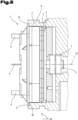
- Fig. 3 The axial flow machine 1 is finally installed or fully integrated into the motor housing 8. While the stator 2 is already in a previous assembly step, as in Fig. 2 shown, especially via the mechanical stop in the engine housing, are positioned in Fig. 3 The rotor 3 and the rotor return 4 are brought into an end position by a screw connection 14. While the holding mechanism holds the stator 2 in position, the actuator with the thread of the screw connection 14 creates a pull/push mechanism which, in conjunction with the holding mechanism, brings the active parts into their end positions.
- the screw connection 14 engages an anchor plate 15 arranged on the rotor return 4 and firmly connected to the rotor return 4 and, supported by the stop of the stator on the stop on the motor housing 5, pulls the anchor plate together with the rotor return plate and the rotor shaft 5 together with the rotor 3 in the installation direction 11.
- the air gap 17 is formed by the movement of the rotor return or the anchor plate.
- the bearing 7 is moved into its end position by the anchor plate (see Figure 3 ), whereby the air gap 16 is formed by moving the rotor shaft 5 and the rotor 3 attached to the rotor shaft 5.
- stator 2 and rotor 3 as well as rotor yoke 4 and rotor 3 must be overcome with the adjusting mechanism of the tension and/or compression element, in particular the screw connection 14, which in this case exerts a tensile force.
- the air gap 16 between stator 2 and rotor 3 on the one hand and the air gap 17 between rotor 3 and rotor yoke 4 on the other hand are formed.
- the distance between the armature plate 15 and the housing creates the air gaps 16 and 17 between the rotor and stator as well as the rotor and the rotor return, as shown in Fig. 3 only shown schematically.
- the sum of the width of the air gaps in Fig. 3 Therefore, according to a preferred embodiment, this results in the bearing-side distance between the housing and the anchor plate.
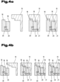
- FIG. 4a and Fig. 4b Basic principles of possible embodiments of the present invention are shown schematically.
- An axial flow machine with active parts 18 and a housing 19 is shown. While in Fig. 4a a configuration of an axial flow machine with 2 active parts is shown schematically, Fig. 4b schematically shows a configuration of an axial flux machine with 3 active parts.
- the active parts 18 are held in a transport configuration by magnetic attraction forces 20 in the transport configuration, in the left-hand part of the figure, in a compact package, in particular a stack.
- the axial flux machine has various stops for installing the package of active parts in the motor housing.
- tension and/or pressure element by which the active parts are pulled apart telescopically when installed or fixed in the motor housing.
- the magnetic attraction forces are at least partially overcome by tensile forces 21 of the tension/pressure element (not shown), for example by screwing the active part to the motor housing.
- the interaction of the tensile forces with the holding mechanism for example by the stop of an active part on the motor housing in the axial installation direction, sets the air gaps between the active parts, for example between the rotor and stator.
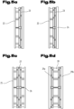
- FIGS 5a to 5d Various configurations of axial flow machines are shown, which are covered by the present invention. They show Figure 5a a configuration with a stator 22 and a rotor 23, Figure 5b a configuration with a stator 22, a rotor 23 and a rotor return part 24, Figure 5c a configuration with two stators 25 and 26 and a rotor 27 arranged between them, Figure 5d a stator 28 arranged between two rotors 29a and 29b.
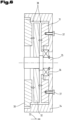
- Fig. 6 a configuration for installing a variant of an axial flow machine with a stator 30, a second stator 31 and a rotor 32 arranged therebetween in a motor housing 34 is shown.
- the first stator 30 is fixed in the installation direction 33 by an axial stop in the motor housing 34.
- the rotor 32 is also positioned in the motor housing 34 by the rotor shaft 35 and a suitable bearing 36, for example by inserting the rotor shaft 35 into the bearing 36 pressed into the motor housing 34, in the installation direction 33, while the second stator 31 is fastened in the motor housing 34 by a screw connection 37.
- the package of the active parts of the axial flow machine with rotor shaft is introduced into the motor housing in the installation direction 33 and is fixed in place by the positioning aids shown, for example the axial stop between the stator 30 and the motor housing 34, the end stop of the bearing 36 in the motor housing 34, and by the pull/push mechanism or the pull and/or push element, which exerts a pulling force on the second stator 31 through the screw connection 37, is brought into position.
- the pulling force at least partially overcomes the magnetic attraction force that acts between the stator 31 and the rotor 32 and creates the air gap 38 between the rotor 32 and the stator 31.
- the stator 31 grips the bearing 36 via a projection or a central part, which is pulled or pushed into the bearing end position when attached to the motor housing via the screw connection 37.
- the bearing 36 is fixed on the one hand via a shaft shoulder and on the other hand via a locking ring on the shaft 35.
- a second configuration for installing a further variant of an axial flow machine with a stator 39 and a first rotor 40 and a second rotor 41 in a motor housing 42 is shown.
- the motor housing 42 is designed in two parts with a first motor housing part 43 and a second motor housing part 44.
- the rotor shaft 45 is also designed with a first rotor shaft part 46 and a second rotor shaft part 47.
- the package of active parts is preferably inserted into the housing with the rotor shaft and the rotor shaft bearing.
- the second motor housing part 44 is then placed on the first motor housing part 43 and fastened to it.
- the first shaft part 46 is then fastened to the bearing by a screw 48 and the second shaft part 47 is displaced from the first shaft part 6 or from the first shaft part 46 in the direction of the screwing in of the screw 48 by the screw end, whereby the distances between the active parts are formed and the corresponding air gaps between the rotors and the stator are formed, counter to the magnetic attraction forces, as shown schematically.
- FIG. 8 A third configuration of an axial flux machine is shown.
- a package of rotor 50, stator 49 and rotor shaft 52 which is transported in a compact package by the magnetic attraction forces 55, is inserted into the motor housing 51.
- the rotor shaft 52 is pressed into the bearing 53 in the motor housing, but other installation variants are also possible here.
- a holding mechanism is ensured by the axial stop of the rotor shaft on the bearing 53 and thus on the motor housing 51.
- the rotor 50 is fixed by the rotor shaft 52 in the direction of the axial installation direction 54.
- the stator 49 is brought into position by a pull/push mechanism.
- stator 49 which initially still rests against the rotor 50 due to the magnetic attraction forces 55, is pulled away from the rotor 50 by the tensile forces of the screw connection 57, whereby the magnetic attraction forces 55 between the rotor 50 and the stator 49 are at least partially overcome.
Landscapes
- Engineering & Computer Science (AREA)
- Power Engineering (AREA)
- Manufacturing & Machinery (AREA)
- Motor Or Generator Frames (AREA)
- Manufacture Of Motors, Generators (AREA)
- Permanent Field Magnets Of Synchronous Machinery (AREA)
- Iron Core Of Rotating Electric Machines (AREA)
- Connection Of Motors, Electrical Generators, Mechanical Devices, And The Like (AREA)
Description
- Die Erfindung betrifft ein Verfahren zum Einbau einer Axialflussmaschine mit mindestens zwei Aktivteilen in ein Motorengehäuse, wovon ein erstes Aktivteil als Rotor mit einer Anzahl von Permanentmagneten und ein zweites Aktivteil als Stator mit einer Anzahl von elektrischen Wicklungen eingerichtet ist, wobei der Rotor und der Stator einander benachbart und drehsicher, in einer Transportkonfiguration in einem platzsparenden, durch die magnetischen Anziehungskräfte der Permanentmagneten gebildeten, Paket, insbesondere in einem Stapel, angeordnet sind.
- Aus dem Stand der Technik sind verschiedene Axialflussmaschinen bekannt. Diese elektrischen Maschinen zeichnen sich durch einfache Bauweise, geringes Gewicht und hohe Drehmomentdichte aus. Elektromaschinen stellen hohe Anforderungen an ihren Zusammenbau und Einbau. Es sind geringe Toleranzen vorgesehen und damit muss beim Einbau von diesen Maschinen mit hoher Präzision vorgegangen werden. Ferner sind Maschinen dieser Art empfindlich gegenüber Verschmutzungen. Mit minimalen Abständen zwischen Rotor und Stator und/oder anderen Aktivteilen ergeben sich so auch hohe Anforderungen an den Transport der Maschinen bzw. deren Teile.
- Üblicherweise weisen Axialflussmaschinen mindestens zwei Aktivteile auf. Beispielsweise können zu einem scheibenförmigen Rotor ein oder mehrere Statoren vorgesehen sein. Der Rotor ist dabei üblicherweise mit einem oder mehreren Permanentmagneten ausgestattet. Der Permanentmagnet kann auch einteilig ausgeführt sein, wobei beispielsweise durch Magnetisierung mehrere Pole gebildet werden können. Zwischen dem Rotor und dem Stator ist ein Luftspalt vorgesehen. Am Stator sind entsprechenden Pole mit Spulenwicklungen ausgebildet, durch deren Bestromung ein geeignetes Magnetfeld ausgebildet wird. Durch die Wechselwirkung zwischen dem Magnetfeld des Stators und dem Magnetfeld des Rotors wird der Rotor bewegt und ein Drehmoment auf eine Rotorwelle übertragen.
- Verschiedentlich sind aus dem Stand der Technik verschiedene Konzepte zur Transportsicherung von elektrischen Maschinen oder deren Teile bekannt. So ist beispielsweise aus der Veröffentlichung
DE10207310A1 bekannt, den Stator mittels einer Aussparung an der Außenseite des Stators über eine Formschlussverbindung und damit die Relativlage von Stator zu Rotor zu fixieren. - Aus der Veröffentlichung
EP1672770B1 ist ein rahmenloser Torque-Motor mit einer Transportsicherung bekannt. Dabei wird zwischen einem Primär- und einem Sekundärteil eine Transportsicherung als Abstandhalter vorgesehen. - Aus der Veröffentlichung
US2017/0117763A1 ist ein Konzept einer speziellen Axialflussmaschine mit einem Verfahren zum Einbau derselben in ein Motorgehäuse bekannt, das sich in der Praxis jedoch als aufwendig gestaltet. - Die aus dem Stand der Technik bekannten Konzepte zu Axialflussmaschinen und insbesondere die Konzepte zum sicheren Transport und einfachen Einbau der Axialflussmaschine bzw. deren Teile erweisen sich in der Praxis als unzureichend, aufwendig und verbesserungswürdig.
- Es ist eine der Aufgaben der vorliegenden Erfindung den Stand der Technik zu verbessern. Es ist eine weitere der Aufgaben der vorliegenden Erfindung das aus dem Stand der Technik bekannte Design einer Axialflussmaschine so weiter zu entwickeln, dass die Axialflussmaschine bzw. deren Aktivteile einfach transportiert und einfach und effizient in ein geeignetes Motorengehäuse eingebaut werden kann/können. Es ist eine der Aufgaben der Erfindung eine Axialflussmaschine nach dem Oberbegriff des Anspruchs 1 zu verbessern.
- Die erfinderische Aufgabe wird nach dem kennzeichnenden Teil des Anspruchs 1 gelöst.
- Nach einer besonderen Ausführungsform der Erfindung ist ein Verfahren zum Einbau einer Axialflussmaschine mit mindestens zwei Aktivteilen in ein Motorengehäuse vorgesehen, wovon ein erstes Aktivteil als Rotor mit einer Anzahl von Permanentmagneten und ein zweites Aktivteil als Stator mit einer Anzahl von elektrischen Wicklungen eingerichtet ist, wobei der Rotor und der Stator einander benachbart und drehsicher, in einer Transportkonfiguration in einem platzsparenden, durch die magnetischen Anziehungskräfte der Permanentmagneten gebildeten, Paket, insbesondere in einem Stapel, angeordnet sind, wobei der Rotor und der Stator in der Transportkonfiguration so unmittelbar benachbart angeordnet werden, dass zumindest in Teilbereichen des Rotors, der Rotor den angrenzenden Stator spielfrei ohne Luftspalt berührt und nachfolgend das Paket in das Motorgehäuse eingeführt und so in dem Motorengehäuse positioniert wird, dass danach mittels einerseits einem an dem Motorengehäuse angeordneten ersten mechanischen, insbesondere in Richtung der Rotorwelle, axialen Anschlages für zumindest eines der mindestens zwei Aktivteile und andererseits einem damit zusammenwirkendem an dem Motorengehäuse angeordneten ersten Zug- und/oder Druckelement, welches - gegen die magnetischen Anziehungskräfte der Permanentmagneten des Rotors zum Stator wirkend - den Abstand zwischen dem Rotor und dem Stator vergrößert, mindestens ein für den Betrieb der Axialflussmaschine erforderlicher Luftspalt zwischen dem Rotor und dem Stator einstellt wird.
- Als Aktivteile werden definitionsgemäß alle jene Teile der Axialflussmaschine bezeichnet, die aktiv im Sinne der Erzeugung und Führung eines Magnetfeldes sind. Das sind einerseits Rotoren, Statoren und andere elektrisch/magnetisch aktive Teile, beispielsweise Bauteile für den magnetischen Rückschluss.
- Beim Handling und der Montage von Rotoren sind besondere Vorkehrungen zu treffen, da einerseits zwischen dem Rotor, den Eisenbauelementen und anderen in der Umgebung positionierten Magneten starke Anziehungskräfte wirken und andererseits die permanenten Magneten des Rotors magnetischen Schmutz und Stäube anziehen.
- Insbesondere wenn Aktivteile, beispielsweise Rotoren und/oder Statoren, einer Axialflussmaschine ohne Gehäuse geliefert werden, ist für den Kunden, der die Axialflussmaschine zusammenbaut und/oder in ein Motorengehäuse einbaut, eine einfache und effiziente Handhabung der Komponenten beim Zusammenbau der Axialflussmaschine von großer Bedeutung.
- Nach einer besonderen Ausführungsform der erfinderischen Lösung wird eine Vormontage der Aktivteile in einer Weise durchgeführt, dass die Komponenten ohne Luftspalt gestapelt werden. Dadurch wird das Magnetfeld der Magnete weitgehend abgeschirmt und es gibt keine Fernwirkung des Magnetfeldes mehr. So kann das Handling beim Transport und Montage-Prozess wesentlich vereinfacht werden. Durch Einbringen der Lagerung in ein Gehäuse und Anziehen der axialen Befestigung stellen sich in der Folge nach einer Ausführungsform der Erfindung automatisch die Luftspalte ein. Ein getrenntes Handling der Komponenten ist nicht nötig. Ein weiterer Vorteil ist nach einer Ausführungsform der Erfindung, dass eine solche Vormontage einem sogenannten End-Of-Line (EOL) - Test unterzogen werden kann und dabei neben funktionellen Tests auch der Einbauprozess selbst beim Kunden nachgestellt werden kann.
- Nach einer besonderen Ausführungsform der Erfindung ist der Rotor durch die magnetischen Anziehungskräfte zwischen den Permanentmagneten des Rotors und dem magnetischen Material in den anderen Aktivteilen positionssicher, insbesondere drehsicher und/oder verschiebungssicher in dem Paket angeordnet. Als drehsicher wird, in diesem Zusammenhang definitionsgemäß, eine Anordnung bezeichnet, in welcher der Rotor durch die anderen Komponenten an einer relativen Drehung, relativ zu den anderen Aktivteilen, behindert wird. In diesem Sinne erfolgt durch die magnetische Anziehung ein, zumindest teilweiser, Kraftschluss, insbesondere durch Wirkung von Reibung, zwischen den Aktivteilen.
- Nach einer besonderen Ausführungsform der Erfindung ist es durch das erfindungsgemäße Verfahren möglich das Auftreten von Streufelder am Rotor zu vermindern und durch den direkten Kontakt der Aktivteile kann eine Verschmutzung des Rotors an den Kontaktflächen wesentlich vermindert oder verhindert werden.
- Erfindungsgemäß kann der Stator und/oder der Rotor eine zumindest teilweise Umspritzung mit einem Kunststoff und/oder einem thermoplastischen Material aufweisen. Eine solche Umspritzung ist integral verbunden und verbleibt auch im Betrieb am Aktivteil haften.
- Erfindungsgemäß weist die Oberfläche der kontaktierenden Aktivteile eine gewisse Unebenheit bzw. Rauheit auf. Aus diesem Grund wird ein solcher Kontakt zwischen den Aktivteilen niemals komplett flächig ausgebildet sein. Ferner kann vorgesehen sein, dass die Oberfläche der Aktivteile eine vorbestimmte geometrische Ausformung, beispielsweise konische geformte Oberflächenanteile, und/oder Struktur, beispielsweise mit vorstehenden Rippen, aufweist. In einem solchen Fall wird die Kontaktierung über diese Struktur bzw. deren Elemente, insbesondere der Rippen, hergestellt.
- Nach einer besonderen Ausführungsform der Erfindung berühren der Rotor und der Stator in der Transportkonfiguration über einen Anteil von mindestens 20%, mindestens 50% oder mindestens 80% der im Paket gegenüberliegenden Flächenanteile einander flächig ohne Luftspalt.
- Nach einer besonderen Ausführungsform sind zwischen den spielfrei sich kontaktierenden Aktivteilen keine Abstandshalter angeordnet.
- Nach einer besonderen Ausführungsform der Erfindung werden die zumindest zwei Aktivteile der Axialflussmaschine beim Einbau und/oder Montage in dem Motorengehäuse von der paketartigen Transportkonfiguration beginnend teleskopartig voneinander entfernt. Dabei werden die für den Betrieb der Axialflussmaschine wesentlichen Luftspalte zwischen dem/den Rotor/Rotoren und den weiteren Aktivteilen eingestellt.
- Nach einer besonderen Ausführungsform der Erfindung ist der Einbauraum des Motorengehäuses für die Positionierung der Axialflussmaschine topfförmig ausgeführt und wird das Paket der mindestens zwei Aktivteile in der Transportkonfiguration von einer ersten Seite in den so gebildeten zumindest teilweise hohlförmigen Einbauraum des Motors so eingeführt, so dass zumindest der Bereich der Berührung zwischen Stator und Rotor seitlich von dem Motorengehäuse abgedeckt ist. Hierdurch werden die Aktivteile von Staub und/oder anderen Verunreinigungen und/oder Beschädigungen geschützt. Nach einer weiteren Ausführungsform werden dadurch auch magnetische Streufelder der magnetisch aktiven Teile minimiert.
- Nach einer besonderen Ausführungsform der Erfindung wird zumindest eines der mindestens zwei Aktivteile der Axialflussmaschine über das erste Zug- und/oder Druckelement in dem Motorengehäuse befestigt. Nach einer besonderen Ausführungsform ermöglicht die Erfindung damit das Befestigen und/oder Positionieren aller Aktivteile in einem Arbeitsgang.
- Nach einer besonderen Ausführungsform der Erfindung ist das erste Zug- und/oder Druckelement als Teil einer Schraubverbindung ausgeführt.
- Nach einer besonderen Ausführungsform der Erfindung wird der Stator über den ersten Anschlag im Einbauraum des Motorengehäuses positioniert. Das erste Zug- und/oder Druckelement vergrößert dabei durch Ausübung einer Zug- und/oder Druckkraft von der, der Seite des Einführens des Paketes in das Motorengehäuse, gegenüberliegenden Seite des Motorengehäuses auf den Rotor den Abstand zwischen Rotor und Stator, wodurch der mindestens eine für den Betrieb der Axialflussmaschine erforderliche Luftspalt zwischen Stator und Rotor eingestellt wird.
- Nach einer besonderen Ausführungsform der Erfindung weisen die zumindest zwei Aktivteile als weiteres Aktivelement ein Rückschlusselement auf, das in dem Paket der Transportkonfiguration auf der dem Stator gegenüberliegenden Seite des Rotors angeordnet wird. Nach der Positionierung des Pakets im Motorengehäuse wird das Rückschlusselement durch das erste Zug- und/oder Druckelement und/oder ein weiteres Zug und/oder Druckelement von dem Rotor entfernt, wodurch ein weiterer Luftspalt des mindestens einen für den Betrieb der Axialflussmaschine erforderliche Luftspalt in diesem Fall zwischen Rotor und Rückschlusselement eingestellt wird.
- Die Erfindung ist nach einer weiteren Ausführungsform ferner durch eine Transportkonfiguration der Aktivteile einer Axialflussmaschine zur Verwendung in einem Verfahren nach einem der vorhergehenden Ansprüche 1 bis 6 gekennzeichnet.
- Die Erfindung ist nach einer weiteren Ausführungsform ferner durch eine Axialflussmaschine in einem Motorgehäuse, welches über ein Verfahren nach einem der Ansprüche 1 bis 6 in das Motorgehäuse eingebaut ist, gekennzeichnet.
- Nach einer besonderen Ausführungsform der Axialflussmaschine sind die Aktivteile in der Transportkonfiguration in der Reihenfolge des Einbaus und/oder dem Montagehandling entsprechend angeordnet.
- Durch diese Maßnahme ist der Einbau der Aktivteile besonders effizient und zeitsparend möglich.
- Nach einer weiteren besonderen Ausführungsform der Axialflussmaschine ist eine Rotorwelle vorgesehen. Das Paket der Aktivteile ist in der Transportkonfiguration bereits auf der Rotorwelle angeordnet.
- Durch diese Maßnahme vereinfacht sich der Einbau der Aktivteile bzw. der Axialflussmaschine wesentlich.
- Nach einer weiteren möglichen Ausführungsform der Erfindung ist an einem ersten der mindestens zwei Aktivteile ein mechanischer Anschlag vorgesehen, der mit einem mechanischen Anschlag im Motorengehäuse zusammenwirken kann, um damit die Einbauposition des ersten Aktivteiles im Motorengehäuse zu definieren.
- Nach einer weiteren möglichen Ausführungsform der Erfindung ist eine Rotorwelle vorgesehen und wird über das Zug/Druck-Element im Zusammenspiel mit dem mechanischen Anschlag im Motorengehäuse bei Einbau des Pakets in das Motorengehäuse über eine Zug- oder Druckkraft, die gegen die magnetischen Anziehungskräfte der Permanentmagneten in Richtung der Achse der Rotorwelle wirkt, ausgeübt, so dass sich, insbesondere am Rotor eine oder mehrere Luftspalte bilden.
- Nach einer weiteren möglichen Ausführungsform der Erfindung weist das Zug/Druck-Element einen Stellmechanismus, vorzugsweise mit einem Gewinde, auf.
- Nach einer weiteren Ausführungsform kann durch den Stellmechanismus der und/oder die Luftspalte eingestellt werden.
- Nach einer weiteren möglichen Ausführungsform der Erfindung ist das erste Aktivteil als ein Stator, das zweite Aktivteil als Rotor eingerichtet und ein drittes Aktivteil als Rückschlussteil, zur Verwirklichung des magnetischen Rückschlusses, vorgesehen.
- Nach einer weiteren möglichen Ausführungsform ist die Erfindung durch eine Axialflussmaschine mit einem ersten Aktivteil, das als Stator und einem zweiten Aktivteil, das als Rotor mit einer Anzahl von Permanentmagneten und einem dritten Aktivteil, das als Rückschlussteil ausgeführt ist, gekennzeichnet. Dabei sind die Aktivteile einander benachbart, insbesondere angrenzend, in einer Transportkonfiguration in einem platzsparenden, durch die magnetischen Anziehungskräfte der Permanentmagneten gebildeten, Paket, insbesondere in einem Stapel, so angeordnet, dass der Rotor zwischen dem Stator und dem Rückschlussteil durch die magnetischen Anziehungskräfte der Permanentmagneten des Rotors vorzugsweise drehsicher angeordnet ist. Die Erfindung ist nach einer besonderen Ausführungsform dadurch gekennzeichnet, dass ein mechanischer Anschlag am Stator vorgesehen ist, der mit einem einer axialen Anschlagsfläche im Motorengehäuse zusammenwirkt und der Rückschlussteil ebenfalls eine axiale Anschlagsfläche aufweist, die mit einer weiteren axialen Anschlagsfläche im Motorengehäuse zusammenwirkt. Über ein Zug-/Druckelement, beispielsweise eine Verschraubung, wird damit ein Stellmechanismus verwirklicht, über den, beispielsweise mit einem Gewinde auf das Rückschlussteil bei der Montage im Motorengehäuse mit der, von dem Zug/Druck-Element ausgeübten, Zug- und/oder Druckkraft von dem Rotor in axialer Richtung entfernt werden kann, so dass zwischen dem Rotor und dem Rückschlussteil ein Luftspalt einstellbar ist. Ferner wird durch Verschieben der Welle und dem daran befestigten Rotor, wobei diese Verlagerung der Welle insbesondere durch das Rückschlussteil, zwischen Stator und Rotor ein weiterer Luftspalt erzeugt, so dass der Rotor im montierten Zustand im Motorengehäuse drehbar ist.
- Nach einer besonderen Ausführungsform der Axialflussmaschine ist eine Rotorwelle vorgesehen und das Paket der Aktivteile ist in der Transportkonfiguration bereits auf der Rotorwelle angeordnet.
- Nach einer besonderen Ausführungsform der Erfindung ist eine Axialflussmaschine mit einem ersten Aktivteil, das als ein erster Stator und einem zweiten Aktivteil, das als Rotor mit einer Anzahl von Permanentmagneten und mit einem dritten Aktivteil, das als zweiter Stator ausgeführt ist, vorgesehen. Dabei sind die Aktivteile einander benachbart, insbesondere angrenzend, in einer Transportkonfiguration in einem platzsparenden, durch die magnetischen Anziehungskräfte der Permanentmagneten gebildeten, Paket, insbesondere in einem Stapel, so angeordnet, dass zwischen dem ersten und zweiten Stator der Rotor durch die magnetischen Anziehungskräfte der Permanentmagneten vorzugsweise drehsicher angeordnet ist. Nach einer besonderen Ausführungsform der Erfindung ist sowohl für den ersten als auch den zweiten Stator ein mechanischer Anschlag im Motorengehäuse vorgesehen. Nach einer weiteren Ausführungsform ist ein Zug- und/oder Druckelement, beispielsweise eine Verschraubung vorgesehen, wodurch der zweite Stator bei Montage mit der, von dem Zug- und/oder Druckelement ausgeübten, Zug- und/oder Druckkraft von dem Rotor entfernt werden kann, so dass sich zwischen dem ersten Stator und dem Rotor einerseits und dem Rotor und dem zweiten Stator andererseits jeweils ein Luftspalt einstellt und der Rotor im montierten Zustand im Motorengehäuse drehbar wird.
- Nach einer weiteren möglichen Ausführungsform der Erfindung ist eine Axialflussmaschine mit einem ersten Aktivteil, das als Stator eingerichtet ist und einem zweiten Aktivteil, das als Rotor mit einer eine Anzahl von Permanentmagneten eingerichtet ist, vorgesehen, wobei die beiden Aktivteile einander benachbart, insbesondere angrenzend in einer Transportkonfiguration in einem platzsparenden, durch die magnetischen Anziehungskräfte der Permanentmagneten gebildeten, Paket, insbesondere in einem Stapel, so angeordnet sind, dass der Rotor durch die magnetischen Anziehungskräfte vorzugsweise drehsicher mit dem Stator verbunden ist und eine Rotorwelle vorgesehen ist, auf welcher der Rotor angeordnet ist. Nach einer besonderen Ausführungsform ist die Erfindung dadurch gekennzeichnet, dass ein mechanischer, insbesondere axialer, Anschlag im Motorengehäuse vorgesehen ist, welcher mit der Rotorwelle zusammenwirkt, so dass beispielsweise, insbesondere einer Lagerung der Rotorwelle über den Anschlag positioniert wird. Nach einer weiteren Ausführungsform ist ein Zug- und/oder Druckelement, insbesondere mit einem Stellmechanismus, beispielsweise einem Gewinde, vorgesehen, wodurch der Stator bei Montage im Motorengehäuse mit einer Zugkraft des Zug- und/oder Druckelements von dem Rotor axial, gegen die Anziehungskräfte der Permanentmagneten und gegen den Anschlag bzw. die Anschläge, insbesondere in Richtung der Rotorwellenachse, entfernt werden kann, so dass sich zwischen dem Stator und dem Rotor ein Luftspalt einstellt und der Rotor im montierten Zustand im Motorengehäuse drehbar wird.
- Nach einer weiteren möglichen Ausführungsform ist die Erfindung durch ein Verfahren zum Einbau einer Axialflussmaschine gekennzeichnet, wobei die Aktivteile der Axialflussmaschine einander benachbart, insbesondere angrenzend, in einer Transportkonfiguration in einem platzsparenden, durch die magnetischen Anziehungskräfte der Permanentmagneten gebildeten, Paket, insbesondere in einem Stapel, transportiert werden, wobei der Rotor durch die magnetischen Anziehungskräfte der Permanentmagneten vorzugsweise drehsicher in dem Paket der Aktivteile angeordnet ist und nachfolgend das Paket in das Motorengehäuse eingelegt wird, wobei zumindest eines der Aktivteile eine einen mechanischen Anschlag für einen entsprechendne Anschlag im Motorengehäuse aufweist und ein Zug- und/oder Druckelement, beispielsweise eine Verschraubung im Motorengehäuse vorgesehen ist, die so ausgestaltet ist, dass bei Montage des Pakets der Aktivteile in das Motorengehäuse die Aktivteile durch Ausübung einer Zug- und/oder Druckkraft, die gegen die magnetischen Anziehungskräfte der Permanentmagneten wirkt und mit dem Anschlag zusammenwirkt, voneinander getrennt werden und sich dabei durch die Montage ein Luftspalt zwischen dem Rotor und den anderen Aktivteilen eingestellt wird und der Rotor im montierten Zustand im Motorengehäuse drehbar wird.
- Mögliche Ausführungsformen der Erfindung sind anhand mehrerer schematischen Zeichnungen, wie folgt, näher erläutert. Es zeigen:
-
Fig. 1 zeigt eine erste mögliche Ausführungsform der erfindungsgemäßen Vorrichtung in einem Transportzustand -
Fig. 2 zeigt die erste Ausführungsform der erfindungsgemäßen Vorrichtung in einem ersten Zustand bei Einbau und vor dem Fixieren bzw. In-Position-bringen der Aktivteile in ein Motorengehäuse -
Fig. 3 zeigt die erste Ausführungsform der erfindungsgemäßen Vorrichtung im eingebauten Zustand mit betriebsfertig positionierten Aktivteilen in einem Motorengehäuse -
Figuren 4a und 4b zeigen schematische Darstellungen von möglichen grundlegenden Prinzipien der Ausnützung der Positionierhilfen bei exemplarischen Ausführungsformen der vorliegenden Erfindung -
Figuren 5a bis 5d verschiedene Konfigurationen von Axialflussmaschinen, die durch die vorliegende Erfindung umfasst sind -
Fig. 6 eine mögliche Konfiguration zum Einbau einer Variante einer Axialflussmaschine in ein Motorengehäuse -
Fig. 7 eine zweite mögliche Konfiguration zum Einbau einer weiteren Variante einer Axialflussmaschine in ein Motorengehäuse -
Fig. 8 eine dritte mögliche Konfiguration zum Einbau einer weiteren Variante einer Axialflussmaschine in ein Motorengehäuse - In
Fig. 1 ist eine Axialflussmaschine 1 teilweise in einer schematischen, isometrischen Projektion dargestellt und teilweise als Schnitt gezeigt. Dabei ist in der schematischen Darstellung ein Stator 2, ein Rotor 3, sowie ein Rotorrückschluss 4 gezeigt. Wie ausFig. 1 ersichtlich ist liegen Stator 2, Rotor 3 und Rotorrückschluss 4 aufeinander auf, d.h. zwischen Rotor 3 und Stator 2 einerseits und Rotor 3 und Rotorrückschluss 4 ist kein Luftspalt gegeben, wobei sich ein flächiger Kontakt zwischen diesen Aktivteiles der Axialflussmaschine ergibt, soweit das aufgrund von Oberflächenrauhigkeiten und mangelnder Planheit der Oberflächen möglich ist. Die Aktivteile der Elektromaschine sind in einem kompakten Paket, gleich einem Stapel, angeordnet. Durch die Permanentmagneten des Rotors 3 und die magnetischen Werkstoffe am Stator 2 und/oder Rotorrückschluss 4 werden magnetische Anziehungskräfte wirksam, die zur Ausbildung des Paketes in der Transportkonfiguration führen und insbesondere, nach einer besonderen Ausführungsform, den Rotor und/oder die anderen Aktivteile auch aufgrund Reibung drehsicher bzw. drehfest, aber auch gegen Verschiebung, insbesondere zumindest teilweise spielfrei, in diesem Stapel zumindest teilweise fixieren. Wie ausFig. 1 ersichtlich ist in diesem Paket auch bereits eine Rotorwelle 5 vorgesehen. Nach einer möglichen Ausführungsform ist beispielsweise der Rotor 3 auf die Welle aufgepresst oder in anderer Form mit der Rotorwelle verbunden, während eines der anderen beiden Aktivteile oder beide Aktivteile beispielsweise noch verschiebbar auf und/oder verschiebbar gegenüber der Welle angeordnet sind. Der Vollständigkeit halber zeigtFig. 1 schematisch noch die elektrischen Anschlüsse 6 des Stators sowie Lager 7 der Rotorwelle. InFig. 2 ist in der Folge ein erster Zustand beim Einbau der Axialflussmaschine 1 in ein Motorgehäuse 8 gezeigt. Wie inFig. 2 ersichtlich weist das Gehäuse 8 einen mechanischen Anschlag 9 auf, der mit einem mechanischen Anschlag 10 des Stators 2 bzw. des Gehäuses des Stators zusammenwirkt. InFig. 2 sind die beiden mechanischen Anschläge in Kontakt und bestimmen so bereits die Endposition des Stators 2 in Einbaurichtung 11, die parallel zur Rotorwellenachse 12 orientiert ist. Der mechanische Anschlag 10 des Stators 2 ist Teil einer Positionierhilfe der Axialflussmaschine. Diese Positionierhilfe kann mannigfaltig ausgestaltet sein und wird hier anhand von Ausführungsbeispielen nur beispielhaft und nicht-einschränkend erläutert. In der vorgestellten beispielhaften Ausführungsform weist die Positionierhilfe den gezeigten mechanischen Anschlag des Stators im Motorengehäuse 8 auf. Der mechanische Anschlag 10 des Stators 2 kann beispielsweise als Ring 13 am Gehäuse des Stators 2 ausgeführt sein. Der Ring weist dann eine axial angeordnete geeignete Anschlagskontur bzw. Anschlagsfläche auf, die mit einem als Gegenanschlag ausgeführten mechanischen Anschlag 9 des Motorengehäuses 8 zusammenwirkt. Wie ausFig. 2 ersichtlich sind die Aktivteile der Axialflussmaschine in diesem Zustand noch immer in dem Stapel angeordnet, d.h. dass der Rotor 3 noch immer ohne Luftspalt durch die magnetischen Kräfte an dem Stator 2 und dem Rotorrückschluss 4 anliegt. Wie dargestellt ist das Motorengehäuse 8 mit einer topfförmigen Einbauraum ausgestattet. Dabei decken seitliche Teile des Motorengehäuses zumindest teilweise Aktivteile und/oder Luftspalte, die sich im eingebauten, positionierten Zustand der Axialflussmaschine im Motorengehäuse ergeben, ab. Topfförmig gestaltete Einbauräume schützen einerseits die eingebaute Maschine optimal und vereinfachen andererseits den betriebsbereiten Einbau bzw. Zusammenbau einer solchen Axialflussmaschine. - In
Fig. 3 ist die Axialflussmaschine 1 schließlich in das Motorgehäuse 8 eingebaut bzw. völlig integriert. Während der Stator 2 bereits in einem vorhergehenden Montageschritt, wie inFig. 2 dargestellt, insbesondere über den mechanischen Anschlag im Motorengehäuse, positioniert wurde, werden inFig. 3 durch eine Verschraubung 14 der Rotor 3 sowie der Rotorrückschluss 4 in eine Endposition gebracht. Während der Haltemechanismus den Stator 2 in Position hält, wird durch den Stellantrieb mit dem Gewinde der Verschraubung 14 ein Zug/Druck-Mechanismus verwirklicht, der in Zusammenwirkung mit dem Haltemechanismus die Aktivteile in ihre Endpositionen bringt. Die Verschraubung 14 greift dabei an einer an dem Rotorrückschluss 4 angeordneten und mit dem Rotorrückschluss 4 fest verbundenen Ankerplatte 15 an und zieht, abgestützt über den Anschlag des Stators am Anschlag am Motorgehäuse 5, die Ankerplatte mitsamt Rotorrückschlussplatte sowie die Rotorwelle 5 mitsamt Rotor 3 in die Einbaurichtung 11. In einem ersten Schritt bildet sich dabei durch Bewegung des Rotorrückschlusses bzw. der Ankerplatte der Luftspalt 17 aus. In einem zweiten Schritt wird das Lager 7 durch die Ankerplatte in seine Endposition (sieheFigur 3 ) bewegt, wodurch sich durch Verschieben der Rotorwelle 5 und des an der Rotorwelle 5 befestigten Rotors 3 der Luftspalt 16 ausbildet. Dabei müssen mit dem Stellmechanismus des Zug- und/oder Druckelementes, insbesondere der Verschraubung 14, das in diesem Fall eine Zugkraft ausübt, die Magnetkräfte zwischen Stator 2 und Rotor 3 sowie Rotorrückschluss 4 und Rotor 3 überwunden werden. In der finalen Einbausituation bilden sich so der Luftspalt 16 zwischen Stator 2 und Rotor 3 einerseits und der Luftspalt 17 zwischen dem Rotor 3 und dem Rotorrückschluss 4 andererseits aus. Ausgehend von der schematischen Darstellung inFig. 2 bildet sich somit durch den Abstand zwischen der Ankerplatte 15 und dem Gehäuse (in Richtung der Wellenachse hin zum Lager 7) durch Verschiebung der Ankerplatte 15 die Luftspalte 16 und 17 zwischen Rotor und Stator sowie Rotor und Rotorrückschluss, wie inFig. 3 nur schematisch dargestellt, aus. Die Summe der Breite der Luftspalte inFig. 3 ergibt deshalb entsprechend einer bevorzugten Ausführungsform den lagerseitigen Abstand zwischen dem Gehäuse und der Ankerplatte. - In den
Fig. 4a und Fig. 4b sind grundlegende Prinzipien möglicher Ausführungsformen der vorliegenden Erfindung schematisch dargestellt. Dabei ist eine Axialflussmaschine mit Aktivteilen 18 und einem Gehäuse 19 dargestellt. Während inFig. 4a eine Konfiguration einer Axialflussmaschine mit 2 Aktivteilen schematisch dargestellt ist, zeigtFig. 4b schematisch eine Konfiguration einer Axialflussmaschine mit 3 Aktivteilen. Die Aktivteile 18 werden dabei in einer Transportkonfiguration durch magnetische Anziehungskräfte 20 in der Transportkonfiguration, jeweils im linken Teil der Abbildung, in einem kompakten Paket, insbesondere einem Stapel gehalten. Die Axialflussmaschine weist verschiedene Anschläge für den Einbau des Pakets der Aktivteile in dem Motorgehäuse auf. Zudem ist ein Zug und/oder Druckelement (nicht dargestellt) durch welche die Aktivteile bei Einbau bzw. Fixierung im Motorengehäuse die Aktivteile teleskopartig auseinandergezogen werden. Beim Einbau der Aktivteile 18 in das Gehäuse werden durch Zugkräfte 21 des Zug/Druck-Elementes (nicht dargestellt), beispielsweise über eine Verschraubung des Aktivteils am Motorengehäuse, die magnetischen Anziehungskräfte zumindest teilweise überwunden. Durch das Zusammenwirken der Zugkräfte mit dem Haltemechanismus, beispielsweise durch den Anschlag eines Aktivteils am Motorengehäuse in axialer Einbaurichtung, stellen sich die Luftspalte zwischen den Aktivteilen, beispielsweise zwischen Rotor und Stator, ein. - In den
Figuren 5a bis 5d sind verschiedene Konfigurationen von Axialflussmaschinen ersichtlich, die durch die vorliegende Erfindung umfasst sind. Es zeigenFigur 5a eine Konfiguration mit einem Stator 22 und einem Rotor 23,Figur 5b eine Konfiguration mit einem Stator 22 einem Rotor 23 und einem Rotorrückschlussteil 24,Figur 5c eine Konfiguration mit zwei Statoren 25 und 26 sowie einem dazwischen angeordneten Rotor 27,Figur 5d einen Stator 28 angeordnet zwischen zwei Rotoren 29a und 29b. - In
Fig. 6 ist eine Konfiguration zum Einbau einer Variante einer Axialflussmaschine mit einem Stator 30, einem zweiten Stator 31 und einem dazwischen angeordneten Rotor 32 in ein Motorengehäuse 34 gezeigt. - Der erste Stator 30 wird dabei in Einbaurichtung 33 durch einen axialen Anschlag im Motorengehäuse 34 fixiert. Der Rotor 32 wird durch die Rotorwelle 35 und ein geeignetes Lager 36 ebenfalls im Motorengehäuse 34, beispielsweise durch Einsetzen der Rotorwelle 35 in das, in das Motorengehäuse 34 eingepresste, Lagers 36, in Einbaurichtung 33 positioniert, während der zweite Stator 31 durch eine Verschraubung 37 im Motorengehäuse 34 befestigt wird. Das Paket der Aktivteile der Axialflussmaschine mit Rotorwelle wird in Einbaurichtung 33 in das Motorgehäuse eingebracht und durch die dargestellten Positionierhilfen, beispielsweise den axialen Anschlag zwischen dem Stator 30 und dem Motorengehäuse 34, den Endanschlag des Lagers 36 im Motorgehäuse 34, und durch den Zug/Druck-Mechanismus bzw. das Zug- und/oder Druckelement, der/das durch die Verschraubung 37 eine Zugkraft auf den zweiten Stator 31 ausübt, in Position gebracht. Die Zugkraft überwindet zumindest teilweise die magnetische Anziehungskraft, die zwischen dem Stator 31 und dem Rotor 32 wirkt und erzeugt den Luftspalt 38 zwischen Rotor 32 und Stator 31. Der Stator 31 greift über eine Auskragung bzw. einen mittleren Teil auf das Lager 36, dass bei der Befestigung über die Verschraubung 37 am Motorengehäuse in die Lagerendposition gezogen bzw. gedrückt wird. Das Lager 36 wird einerseits über einen Wellenabsatz und andererseits über einen Sicherungsring auf der Welle 35 fixiert.
- In
Fig. 7 ist eine zweite Konfiguration zum Einbau einer weiteren Variante einer Axialflussmaschine mit einem Stator 39 und einem ersten Rotor 40 und einem zweiten Rotor 41 in ein Motorengehäuse 42 dargestellt. Das Motorengehäuse 42 ist dabei zweiteilig mit einem ersten Motorengehäuseteil 43 und einem zweiten Motorengehäuseteil 44 ausgeführt. Ebenso ist die Rotorwelle 45 mit einem ersten Rotorwellenteil 46 und einem zweiten Rotorwellenteil 47 ausgeführt. Beim Einbau der Axialflussmaschine in das Motorengehäuse 42 wird das Paket der Aktivteile vorzugsweise mit der Rotorwelle und dem Rotorwellenlager in das Gehäuse eingesetzt. Danach wird der zweite Motorengehäuseteil 44 auf das erste Motorengehäuseteil 43 aufgesetzt und an diesem befestigt. Durch eine Schraube 48 wird danach der erste Wellenteil 46 am Lager befestigt und durch das Schraubenende der zweite Wellenteil 47 vom ersten Wellenteil 6 bzw. aus dem ersten Wellenteil 46 in Richtung der Einschraubrichtung der Schraube 48 verschoben, wodurch sich die Abstände zwischen den Aktivteilen ausbilden und die entsprechenden Luftspalte zwischen den Rotoren und dem Stator, entgegen den magnetischen Anziehungskräften, wie schematisch dargestellt, ausbilden. - In
Fig. 8 ist eine dritte Konfiguration einer Axialflussmaschine dargestellt. Ein Paket aus Rotor 50, Stator 49 und Rotorwelle 52, das durch die magnetischen Anziehungskräfte 55 in einem kompakten Paket transportiert wird, wird in das Motorengehäuse 51 eingesetzt. Dabei wird beispielsweise die Rotorwelle 52 in das Lager 53 im Motorengehäuse eingepresst, aber auch andere Varianten des Einbaus sind hier möglich. Ein Haltemechanismus ist in diesem Fall durch den axialen Anschlag der Rotorwelle am Lager 53 bzw. damit am Motorengehäuse 51, gewährleistet. Der Rotor 50 ist durch die Rotorwelle 52 in Richtung der axialen Einbaurichtung 54 fixiert. Der Stator 49 wird durch einen Zug/Druck-Mechanismus in Position gebracht. Dabei wird der Stator 49, der anfangs durch die magnetischen Anziehungskräfte 55 noch an dem Rotor 50 anliegt, durch die Zugkräfte der Verschraubung 57 vom Rotor 50 beanstandet, wobei die magnetischen Anziehungskräfte 55 zwischen Rotor 50 und Stator 49 zumindest teilweise überwunden werden. Damit wird der Luftspalt 56 zwischen Rotor 50 und Stator 49 eingestellt und schließlich der Stator 49 am Motorengehäuse 51 befestigt.
Claims (8)
- Verfahren zum Einbau einer Axialflussmaschine (1) mit mindestens zwei Aktivteilen (18) in ein Motorengehäuse (8), wovon ein erstes Aktivteil als Rotor (3) mit einer Anzahl von Permanentmagneten und ein zweites Aktivteil als Stator (2) mit einer Anzahl von elektrischen Wicklungen eingerichtet ist, wobei der Rotor (3) und der Stator (2) einander benachbart und drehsicher, in einer Transportkonfiguration in einem platzsparenden, durch die magnetischen Anziehungskräfte der Permanentmagneten gebildeten, Paket, insbesondere in einem Stapel, angeordnet sind, wobei
der Rotor (3) und der Stator (2) in der Transportkonfiguration so unmittelbar benachbart angeordnet werden, dass zumindest in Teilbereichen des Rotors (3), der Rotor (3) den angrenzenden Stator (2), insbesondere spielfrei, ohne Luftspalt (16) berührt und nachfolgend das Paket in das Motorgehäuse (8) eingeführt und so in dem Motorengehäuse (8) positioniert wird, dass danach mittels einerseits einem an dem Motorengehäuse (8) angeordneten ersten mechanischen Anschlages (9) für zumindest eines der mindestens zwei Aktivteile (18) und andererseits einem damit zusammenwirkendem an dem Motorengehäuse (8) angeordneten ersten Zug- und/oder Druckelement, welches - gegen die magnetischen Anziehungskräfte der Permanentmagneten des Rotors (3) zum Stator (2) wirkend - den Abstand zwischen dem Rotor (3) und dem Stator (2) vergrößert, mindestens ein für den Betrieb der Axialflussmaschine erforderlicher Luftspalt (16) zwischen dem Rotor (3) und dem Stator (2) eingestellt wird. - Verfahren zum Einbau einer Axialflussmaschine (1) nach Anspruch 1 , dadurch gekennzeichnet, dass der Einbauraum des Motorengehäuse (8) für die Positionierung der Axialflussmaschine (1) topfförmig ausgeführt ist und das Paket der mindestens zwei Aktivteile (18) in der Transportkonfiguration von einer ersten Seite in den so gebildeten zumindest teilweise hohlförmigen Einbauraum des Motors so eingeführt wird, so dass zumindest der Bereich der Berührung zwischen Stator (2) und Rotor (3) seitlich von dem Motorengehäuse (8) abgedeckt ist.
- Verfahren zum Einbau einer Axialflussmaschine (1) nach einem der vorhergehenden Ansprüche, dadurch gekennzeichnet, dass zumindest eines der mindestens zwei Aktivteile (18) der Axialflussmaschine (1) über das erste Zug- und/oder Druckelement in dem Motorengehäuse (8) befestigt wird.
- Verfahren zum Einbau einer Axialflussmaschine (1) nach einem der vorhergehenden Ansprüche, dadurch gekennzeichnet, dass das erste Zug- und/oder Druckelement als Teil einer Schraubverbindung (14) ausgeführt ist.
- Verfahren zum Einbau einer Axialflussmaschine (1) nach einem der vorhergehenden Ansprüche, dadurch gekennzeichnet, dass der Stator (2) über den ersten Anschlag (9) im Einbauraum des Motorengehäuses (8) positioniert wird und das erste Zug- und/oder Druckelement von der, der Seite des Einführens des Paketes in das Motorengehäuse (8), gegenüberliegenden Seite des Motorengehäuses (8) durch Ausübung einer Zug- und/oder Druckkraft auf den Rotor (3) den Abstand zwischen Rotor (3) und Stator (2) vergrößert, wodurch der mindestens eine für den Betrieb der Axialflussmaschine erforderliche Luftspalt (16) zwischen Stator (2) und Rotor (3) eingestellt wird.
- Verfahren zum Einbau einer Axialflussmaschine (1) nach Anspruch 5, dadurch gekennzeichnet, dass die zumindest zwei Aktivteile (18) als weiteres Aktivelement ein Rückschlusselement (4) aufweisen, das in dem Paket der Transportkonfiguration auf der dem Stator (2) gegenüberliegenden Seite des Rotors (3) angeordnet wird und nach der Positionierung des Pakets im Motorengehäuse (8) das Rückschlusselement (4) durch das erste Zug- und/oder Druckelement und/oder ein weiteres Zug und/oder Druckelement von dem Rotor (3) entfernt wird, wodurch ein weiterer Luftspalt (17) des mindestens einen für den Betrieb der Axialflussmaschine (1) erforderliche Luftspalt (16) in diesem Fall zwischen Rotor (3) und Rückschlusselement (4) eingestellt wird.
- Transportkonfiguration der Aktivteile einer Axialflussmaschine (1) zur Verwendung in einem Verfahren nach einem der vorhergehenden Ansprüche 1 bis 6, wobei der Rotor (3) und der Stator (2) einander benachbart und drehsicher, in einem platzsparenden, durch die magnetischen Anziehungskräfte der Permanentmagneten gebildeten, Paket, insbesondere in einem Stapel, angeordnet sind, wobei der Rotor (3) und der Stator (2) in der Transportkonfiguration so unmittelbar benachbart angeordnet werden, dass zumindest in Teilbereichen des Rotors (3), der Rotor (3) den angrenzenden Stator (2), insbesondere spielfrei, ohne Luftspalt (16) berührt.
- Axialflussmaschine (1) in einem Motorgehäuse (8), welches über ein Verfahren nach einem der Ansprüche 1 bis 6 in das Motorgehäuse (8) eingebaut ist.
Applications Claiming Priority (2)
| Application Number | Priority Date | Filing Date | Title |
|---|---|---|---|
| AT509912020 | 2020-11-13 | ||
| PCT/AT2021/060431 WO2022099344A1 (de) | 2020-11-13 | 2021-11-12 | Verfahren zum einbau einer axialflussmaschine |
Publications (2)
| Publication Number | Publication Date |
|---|---|
| EP4244960A1 EP4244960A1 (de) | 2023-09-20 |
| EP4244960B1 true EP4244960B1 (de) | 2025-01-01 |
Family
ID=78844988
Family Applications (1)
| Application Number | Title | Priority Date | Filing Date |
|---|---|---|---|
| EP21823723.8A Active EP4244960B1 (de) | 2020-11-13 | 2021-11-12 | Verfahren zum einbau einer axialflussmaschine |
Country Status (4)
| Country | Link |
|---|---|
| US (1) | US12395051B2 (de) |
| EP (1) | EP4244960B1 (de) |
| CN (1) | CN116508246A (de) |
| WO (1) | WO2022099344A1 (de) |
Families Citing this family (2)
| Publication number | Priority date | Publication date | Assignee | Title |
|---|---|---|---|---|
| DE102023104840A1 (de) * | 2023-02-28 | 2024-08-29 | Sick Ag | Positionsbestimmungsvorrichtung und Positionsbestimmungssystem sowie Herstellungsverfahren hierfür |
| WO2024223686A1 (de) | 2023-04-27 | 2024-10-31 | Miba Emobility Gmbh | Axialfluss-maschine |
Citations (1)
| Publication number | Priority date | Publication date | Assignee | Title |
|---|---|---|---|---|
| DE10207310A1 (de) * | 2002-02-21 | 2003-09-04 | Mafell Ag | Motoreinheit |
Family Cites Families (4)
| Publication number | Priority date | Publication date | Assignee | Title |
|---|---|---|---|---|
| DE102004060506A1 (de) | 2004-12-16 | 2006-06-29 | Etel S.A. | Rahmenloser Torque-Motor mit Transportsicherung |
| GB201518387D0 (en) | 2015-10-16 | 2015-12-02 | Yasa Motors Ltd | Axial flux machine |
| US10985639B2 (en) * | 2019-03-08 | 2021-04-20 | Regal Beloit America, Inc. | Axial flux electrical motor assembly and methods of assembling the same |
| EP3832860A1 (de) * | 2019-12-05 | 2021-06-09 | Phi-Power AG | Einseitige elektrische axialflussmaschine mit zusätzlichem passivem stator |
-
2021
- 2021-11-12 WO PCT/AT2021/060431 patent/WO2022099344A1/de not_active Ceased
- 2021-11-12 EP EP21823723.8A patent/EP4244960B1/de active Active
- 2021-11-12 US US18/035,983 patent/US12395051B2/en active Active
- 2021-11-12 CN CN202180073530.7A patent/CN116508246A/zh active Pending
Patent Citations (1)
| Publication number | Priority date | Publication date | Assignee | Title |
|---|---|---|---|---|
| DE10207310A1 (de) * | 2002-02-21 | 2003-09-04 | Mafell Ag | Motoreinheit |
Also Published As
| Publication number | Publication date |
|---|---|
| WO2022099344A1 (de) | 2022-05-19 |
| US12395051B2 (en) | 2025-08-19 |
| CN116508246A (zh) | 2023-07-28 |
| EP4244960A1 (de) | 2023-09-20 |
| US20240022148A1 (en) | 2024-01-18 |
Similar Documents
| Publication | Publication Date | Title |
|---|---|---|
| DE29822286U1 (de) | Stator für einen Elektromotor | |
| DE112016006720T5 (de) | Stator, Motor, Gebläse, Staubsauger und Verfahren zum Befestigen eines Hallsensors | |
| EP0559665A1 (de) | Stator für eine elektrische maschine. | |
| DE112016007067T5 (de) | Folgepoltyp-rotor, elektromotor, klimaanlage und verfahren zur herstellung eines folgepoltyp-rotors | |
| DE10049107A1 (de) | Elektromotorkonstruktion | |
| EP3462582A1 (de) | Permanentmagnetrotor, verfahren zu seiner herstellung und magnetisierungsvorrichtung | |
| WO2018219390A1 (de) | Kostenoptimierter rotor einer elektrischen maschine | |
| WO2022099344A1 (de) | Verfahren zum einbau einer axialflussmaschine | |
| DE602004012665T2 (de) | Klauenpolenschrittmotor mit reduzierten radialen Dimensionen ohne Schäden der Leistungseigenschaften | |
| DE102008054330A1 (de) | Zweiteiliges Motorgehäuse mit Bajonett-Verbindung | |
| DE102014100497A1 (de) | Drehmagnet | |
| DE112006002546T5 (de) | Gleichstrommotor mit asymmetrischen Polen | |
| DE19914943C1 (de) | Reluktanzmaschine mit wenigstens zwei, je mit einer Erregerwicklung versehenen ausgeprägten Statorpolen und Verfahren zur Herstellung des Stators einer solchen Reluktanzmaschine | |
| EP1348221B1 (de) | Elektromagnet mit magnetanker | |
| DE102012106330B4 (de) | Spulenkern für elektromagnetischen Antrieb und selbiger sowie Verfahren zu dessen Herstellung | |
| EP0780956B1 (de) | Dauermagnetläufer für Klauenpolschrittmotor | |
| DE102006017233B4 (de) | Rotoranordnung für eine elektrische Maschine und Klauenpolmotor | |
| DE102020113725A1 (de) | Elektrische axialflussmaschine und verfahren des zusammenbaus derselben | |
| EP4092696A1 (de) | Elektromagnetischer aktuator | |
| DE102020215269A1 (de) | Elektrischer Stator für ein Expansionsventil | |
| EP1936641B1 (de) | Kaskadenförmig angeordneter Magnetaktor | |
| EP2652861A2 (de) | Magnethalteeinrichtung | |
| DE102022122446A1 (de) | Zweiphasiger Motor, insbesondere zum Antrieb eines Förderbandes | |
| DE102017203907B4 (de) | Elektromotor, insbesondere für einen Komfortantrieb in einem Kraftfahrzeug und Getriebe-Antriebseinrichtung | |
| DE112017004346T5 (de) | Stator und herstellverfahren eines stators |
Legal Events
| Date | Code | Title | Description |
|---|---|---|---|
| STAA | Information on the status of an ep patent application or granted ep patent |
Free format text: STATUS: UNKNOWN |
|
| STAA | Information on the status of an ep patent application or granted ep patent |
Free format text: STATUS: THE INTERNATIONAL PUBLICATION HAS BEEN MADE |
|
| PUAI | Public reference made under article 153(3) epc to a published international application that has entered the european phase |
Free format text: ORIGINAL CODE: 0009012 |
|
| STAA | Information on the status of an ep patent application or granted ep patent |
Free format text: STATUS: REQUEST FOR EXAMINATION WAS MADE |
|
| 17P | Request for examination filed |
Effective date: 20230612 |
|
| AK | Designated contracting states |
Kind code of ref document: A1 Designated state(s): AL AT BE BG CH CY CZ DE DK EE ES FI FR GB GR HR HU IE IS IT LI LT LU LV MC MK MT NL NO PL PT RO RS SE SI SK SM TR |
|
| DAV | Request for validation of the european patent (deleted) | ||
| DAX | Request for extension of the european patent (deleted) | ||
| GRAP | Despatch of communication of intention to grant a patent |
Free format text: ORIGINAL CODE: EPIDOSNIGR1 |
|
| STAA | Information on the status of an ep patent application or granted ep patent |
Free format text: STATUS: GRANT OF PATENT IS INTENDED |
|
| INTG | Intention to grant announced |
Effective date: 20240625 |
|
| GRAS | Grant fee paid |
Free format text: ORIGINAL CODE: EPIDOSNIGR3 |
|
| GRAA | (expected) grant |
Free format text: ORIGINAL CODE: 0009210 |
|
| STAA | Information on the status of an ep patent application or granted ep patent |
Free format text: STATUS: THE PATENT HAS BEEN GRANTED |
|
| AK | Designated contracting states |
Kind code of ref document: B1 Designated state(s): AL AT BE BG CH CY CZ DE DK EE ES FI FR GB GR HR HU IE IS IT LI LT LU LV MC MK MT NL NO PL PT RO RS SE SI SK SM TR |
|
| REG | Reference to a national code |
Ref country code: GB Ref legal event code: FG4D Free format text: NOT ENGLISH |
|
| REG | Reference to a national code |
Ref country code: CH Ref legal event code: EP |
|
| REG | Reference to a national code |
Ref country code: DE Ref legal event code: R096 Ref document number: 502021006312 Country of ref document: DE |
|
| REG | Reference to a national code |
Ref country code: IE Ref legal event code: FG4D Free format text: LANGUAGE OF EP DOCUMENT: GERMAN |
|
| P01 | Opt-out of the competence of the unified patent court (upc) registered |
Free format text: CASE NUMBER: APP_10066/2025 Effective date: 20250227 |
|
| REG | Reference to a national code |
Ref country code: LT Ref legal event code: MG9D |
|
| REG | Reference to a national code |
Ref country code: NL Ref legal event code: MP Effective date: 20250101 |
|
| PG25 | Lapsed in a contracting state [announced via postgrant information from national office to epo] |
Ref country code: NL Free format text: LAPSE BECAUSE OF FAILURE TO SUBMIT A TRANSLATION OF THE DESCRIPTION OR TO PAY THE FEE WITHIN THE PRESCRIBED TIME-LIMIT Effective date: 20250101 |
|
| PG25 | Lapsed in a contracting state [announced via postgrant information from national office to epo] |
Ref country code: FI Free format text: LAPSE BECAUSE OF FAILURE TO SUBMIT A TRANSLATION OF THE DESCRIPTION OR TO PAY THE FEE WITHIN THE PRESCRIBED TIME-LIMIT Effective date: 20250101 |
|
| PG25 | Lapsed in a contracting state [announced via postgrant information from national office to epo] |
Ref country code: PL Free format text: LAPSE BECAUSE OF FAILURE TO SUBMIT A TRANSLATION OF THE DESCRIPTION OR TO PAY THE FEE WITHIN THE PRESCRIBED TIME-LIMIT Effective date: 20250101 |
|
| PG25 | Lapsed in a contracting state [announced via postgrant information from national office to epo] |
Ref country code: ES Free format text: LAPSE BECAUSE OF FAILURE TO SUBMIT A TRANSLATION OF THE DESCRIPTION OR TO PAY THE FEE WITHIN THE PRESCRIBED TIME-LIMIT Effective date: 20250101 |
|
| PG25 | Lapsed in a contracting state [announced via postgrant information from national office to epo] |
Ref country code: NO Free format text: LAPSE BECAUSE OF FAILURE TO SUBMIT A TRANSLATION OF THE DESCRIPTION OR TO PAY THE FEE WITHIN THE PRESCRIBED TIME-LIMIT Effective date: 20250401 Ref country code: IS Free format text: LAPSE BECAUSE OF FAILURE TO SUBMIT A TRANSLATION OF THE DESCRIPTION OR TO PAY THE FEE WITHIN THE PRESCRIBED TIME-LIMIT Effective date: 20250501 |
|
| PG25 | Lapsed in a contracting state [announced via postgrant information from national office to epo] |
Ref country code: HR Free format text: LAPSE BECAUSE OF FAILURE TO SUBMIT A TRANSLATION OF THE DESCRIPTION OR TO PAY THE FEE WITHIN THE PRESCRIBED TIME-LIMIT Effective date: 20250101 |
|
| PG25 | Lapsed in a contracting state [announced via postgrant information from national office to epo] |
Ref country code: LV Free format text: LAPSE BECAUSE OF FAILURE TO SUBMIT A TRANSLATION OF THE DESCRIPTION OR TO PAY THE FEE WITHIN THE PRESCRIBED TIME-LIMIT Effective date: 20250101 Ref country code: PT Free format text: LAPSE BECAUSE OF FAILURE TO SUBMIT A TRANSLATION OF THE DESCRIPTION OR TO PAY THE FEE WITHIN THE PRESCRIBED TIME-LIMIT Effective date: 20250502 |
|
| PG25 | Lapsed in a contracting state [announced via postgrant information from national office to epo] |
Ref country code: BG Free format text: LAPSE BECAUSE OF FAILURE TO SUBMIT A TRANSLATION OF THE DESCRIPTION OR TO PAY THE FEE WITHIN THE PRESCRIBED TIME-LIMIT Effective date: 20250101 Ref country code: GR Free format text: LAPSE BECAUSE OF FAILURE TO SUBMIT A TRANSLATION OF THE DESCRIPTION OR TO PAY THE FEE WITHIN THE PRESCRIBED TIME-LIMIT Effective date: 20250402 |
|
| PG25 | Lapsed in a contracting state [announced via postgrant information from national office to epo] |
Ref country code: CZ Free format text: LAPSE BECAUSE OF FAILURE TO SUBMIT A TRANSLATION OF THE DESCRIPTION OR TO PAY THE FEE WITHIN THE PRESCRIBED TIME-LIMIT Effective date: 20250101 |
|
| PG25 | Lapsed in a contracting state [announced via postgrant information from national office to epo] |
Ref country code: SE Free format text: LAPSE BECAUSE OF FAILURE TO SUBMIT A TRANSLATION OF THE DESCRIPTION OR TO PAY THE FEE WITHIN THE PRESCRIBED TIME-LIMIT Effective date: 20250101 |
|
| REG | Reference to a national code |
Ref country code: DE Ref legal event code: R097 Ref document number: 502021006312 Country of ref document: DE |
|
| PG25 | Lapsed in a contracting state [announced via postgrant information from national office to epo] |
Ref country code: SM Free format text: LAPSE BECAUSE OF FAILURE TO SUBMIT A TRANSLATION OF THE DESCRIPTION OR TO PAY THE FEE WITHIN THE PRESCRIBED TIME-LIMIT Effective date: 20250101 |
|
| PG25 | Lapsed in a contracting state [announced via postgrant information from national office to epo] |
Ref country code: DK Free format text: LAPSE BECAUSE OF FAILURE TO SUBMIT A TRANSLATION OF THE DESCRIPTION OR TO PAY THE FEE WITHIN THE PRESCRIBED TIME-LIMIT Effective date: 20250101 |
|
| PG25 | Lapsed in a contracting state [announced via postgrant information from national office to epo] |
Ref country code: IT Free format text: LAPSE BECAUSE OF FAILURE TO SUBMIT A TRANSLATION OF THE DESCRIPTION OR TO PAY THE FEE WITHIN THE PRESCRIBED TIME-LIMIT Effective date: 20250101 |
|
| PG25 | Lapsed in a contracting state [announced via postgrant information from national office to epo] |
Ref country code: EE Free format text: LAPSE BECAUSE OF FAILURE TO SUBMIT A TRANSLATION OF THE DESCRIPTION OR TO PAY THE FEE WITHIN THE PRESCRIBED TIME-LIMIT Effective date: 20250101 |
|
| PG25 | Lapsed in a contracting state [announced via postgrant information from national office to epo] |
Ref country code: RO Free format text: LAPSE BECAUSE OF FAILURE TO SUBMIT A TRANSLATION OF THE DESCRIPTION OR TO PAY THE FEE WITHIN THE PRESCRIBED TIME-LIMIT Effective date: 20250101 |
|
| PG25 | Lapsed in a contracting state [announced via postgrant information from national office to epo] |
Ref country code: SK Free format text: LAPSE BECAUSE OF FAILURE TO SUBMIT A TRANSLATION OF THE DESCRIPTION OR TO PAY THE FEE WITHIN THE PRESCRIBED TIME-LIMIT Effective date: 20250101 |
|
| PLBE | No opposition filed within time limit |
Free format text: ORIGINAL CODE: 0009261 |
|
| STAA | Information on the status of an ep patent application or granted ep patent |
Free format text: STATUS: NO OPPOSITION FILED WITHIN TIME LIMIT |
|
| 26N | No opposition filed |
Effective date: 20251002 |
|
| PGFP | Annual fee paid to national office [announced via postgrant information from national office to epo] |
Ref country code: DE Payment date: 20251118 Year of fee payment: 5 |
|
| PGFP | Annual fee paid to national office [announced via postgrant information from national office to epo] |
Ref country code: GB Payment date: 20251125 Year of fee payment: 5 |
|
| PGFP | Annual fee paid to national office [announced via postgrant information from national office to epo] |
Ref country code: AT Payment date: 20260113 Year of fee payment: 5 |
|
| PGFP | Annual fee paid to national office [announced via postgrant information from national office to epo] |
Ref country code: FR Payment date: 20251126 Year of fee payment: 5 |
|
| REG | Reference to a national code |
Ref country code: DE Ref legal event code: R081 Ref document number: 502021006312 Country of ref document: DE Owner name: WEBER-HYDRAULIK GMBH, DE Free format text: FORMER OWNER: MIBA EMOBILITY GMBH, LAAKIRCHEN, AT |
|
| REG | Reference to a national code |
Ref country code: GB Ref legal event code: 732E Free format text: REGISTERED BETWEEN 20260129 AND 20260204 |