EP4244520B1 - Mechanische spurverfolgungshalterung - Google Patents
Mechanische spurverfolgungshalterung Download PDFInfo
- Publication number
- EP4244520B1 EP4244520B1 EP21810294.5A EP21810294A EP4244520B1 EP 4244520 B1 EP4244520 B1 EP 4244520B1 EP 21810294 A EP21810294 A EP 21810294A EP 4244520 B1 EP4244520 B1 EP 4244520B1
- Authority
- EP
- European Patent Office
- Prior art keywords
- tracking
- torsion spring
- mount
- arm
- mechanical
- Prior art date
- Legal status (The legal status is an assumption and is not a legal conclusion. Google has not performed a legal analysis and makes no representation as to the accuracy of the status listed.)
- Active
Links
Images




Classifications
-
- F—MECHANICAL ENGINEERING; LIGHTING; HEATING; WEAPONS; BLASTING
- F16—ENGINEERING ELEMENTS AND UNITS; GENERAL MEASURES FOR PRODUCING AND MAINTAINING EFFECTIVE FUNCTIONING OF MACHINES OR INSTALLATIONS; THERMAL INSULATION IN GENERAL
- F16M—FRAMES, CASINGS OR BEDS OF ENGINES, MACHINES OR APPARATUS, NOT SPECIFIC TO ENGINES, MACHINES OR APPARATUS PROVIDED FOR ELSEWHERE; STANDS; SUPPORTS
- F16M11/00—Stands or trestles as supports for apparatus or articles placed thereon ; Stands for scientific apparatus such as gravitational force meters
- F16M11/02—Heads
- F16M11/04—Means for attachment of apparatus; Means allowing adjustment of the apparatus relatively to the stand
- F16M11/06—Means for attachment of apparatus; Means allowing adjustment of the apparatus relatively to the stand allowing pivoting
- F16M11/12—Means for attachment of apparatus; Means allowing adjustment of the apparatus relatively to the stand allowing pivoting in more than one direction
- F16M11/14—Means for attachment of apparatus; Means allowing adjustment of the apparatus relatively to the stand allowing pivoting in more than one direction with ball-joint
-
- F—MECHANICAL ENGINEERING; LIGHTING; HEATING; WEAPONS; BLASTING
- F16—ENGINEERING ELEMENTS AND UNITS; GENERAL MEASURES FOR PRODUCING AND MAINTAINING EFFECTIVE FUNCTIONING OF MACHINES OR INSTALLATIONS; THERMAL INSULATION IN GENERAL
- F16M—FRAMES, CASINGS OR BEDS OF ENGINES, MACHINES OR APPARATUS, NOT SPECIFIC TO ENGINES, MACHINES OR APPARATUS PROVIDED FOR ELSEWHERE; STANDS; SUPPORTS
- F16M11/00—Stands or trestles as supports for apparatus or articles placed thereon ; Stands for scientific apparatus such as gravitational force meters
- F16M11/02—Heads
- F16M11/04—Means for attachment of apparatus; Means allowing adjustment of the apparatus relatively to the stand
- F16M11/06—Means for attachment of apparatus; Means allowing adjustment of the apparatus relatively to the stand allowing pivoting
- F16M11/08—Means for attachment of apparatus; Means allowing adjustment of the apparatus relatively to the stand allowing pivoting around a vertical axis, e.g. panoramic heads
-
- F—MECHANICAL ENGINEERING; LIGHTING; HEATING; WEAPONS; BLASTING
- F16—ENGINEERING ELEMENTS AND UNITS; GENERAL MEASURES FOR PRODUCING AND MAINTAINING EFFECTIVE FUNCTIONING OF MACHINES OR INSTALLATIONS; THERMAL INSULATION IN GENERAL
- F16M—FRAMES, CASINGS OR BEDS OF ENGINES, MACHINES OR APPARATUS, NOT SPECIFIC TO ENGINES, MACHINES OR APPARATUS PROVIDED FOR ELSEWHERE; STANDS; SUPPORTS
- F16M11/00—Stands or trestles as supports for apparatus or articles placed thereon ; Stands for scientific apparatus such as gravitational force meters
- F16M11/20—Undercarriages with or without wheels
- F16M11/2007—Undercarriages with or without wheels comprising means allowing pivoting adjustment
- F16M11/2014—Undercarriages with or without wheels comprising means allowing pivoting adjustment around a vertical axis
-
- G—PHYSICS
- G02—OPTICS
- G02B—OPTICAL ELEMENTS, SYSTEMS OR APPARATUS
- G02B23/00—Telescopes, e.g. binoculars; Periscopes; Instruments for viewing the inside of hollow bodies; Viewfinders; Optical aiming or sighting devices
- G02B23/16—Housings; Caps; Mountings; Supports, e.g. with counterweight
- G02B23/165—Equatorial mounts
-
- G—PHYSICS
- G02—OPTICS
- G02B—OPTICAL ELEMENTS, SYSTEMS OR APPARATUS
- G02B7/00—Mountings, adjusting means, or light-tight connections, for optical elements
-
- G—PHYSICS
- G03—PHOTOGRAPHY; CINEMATOGRAPHY; ANALOGOUS TECHNIQUES USING WAVES OTHER THAN OPTICAL WAVES; ELECTROGRAPHY; HOLOGRAPHY
- G03B—APPARATUS OR ARRANGEMENTS FOR TAKING PHOTOGRAPHS OR FOR PROJECTING OR VIEWING THEM; APPARATUS OR ARRANGEMENTS EMPLOYING ANALOGOUS TECHNIQUES USING WAVES OTHER THAN OPTICAL WAVES; ACCESSORIES THEREFOR
- G03B17/00—Details of cameras or camera bodies; Accessories therefor
- G03B17/56—Accessories
- G03B17/561—Support related camera accessories
-
- G—PHYSICS
- G03—PHOTOGRAPHY; CINEMATOGRAPHY; ANALOGOUS TECHNIQUES USING WAVES OTHER THAN OPTICAL WAVES; ELECTROGRAPHY; HOLOGRAPHY
- G03B—APPARATUS OR ARRANGEMENTS FOR TAKING PHOTOGRAPHS OR FOR PROJECTING OR VIEWING THEM; APPARATUS OR ARRANGEMENTS EMPLOYING ANALOGOUS TECHNIQUES USING WAVES OTHER THAN OPTICAL WAVES; ACCESSORIES THEREFOR
- G03B17/00—Details of cameras or camera bodies; Accessories therefor
- G03B17/56—Accessories
- G03B17/566—Accessory clips, holders, shoes to attach accessories to camera
-
- F—MECHANICAL ENGINEERING; LIGHTING; HEATING; WEAPONS; BLASTING
- F16—ENGINEERING ELEMENTS AND UNITS; GENERAL MEASURES FOR PRODUCING AND MAINTAINING EFFECTIVE FUNCTIONING OF MACHINES OR INSTALLATIONS; THERMAL INSULATION IN GENERAL
- F16M—FRAMES, CASINGS OR BEDS OF ENGINES, MACHINES OR APPARATUS, NOT SPECIFIC TO ENGINES, MACHINES OR APPARATUS PROVIDED FOR ELSEWHERE; STANDS; SUPPORTS
- F16M11/00—Stands or trestles as supports for apparatus or articles placed thereon ; Stands for scientific apparatus such as gravitational force meters
- F16M11/02—Heads
- F16M11/18—Heads with mechanism for moving the apparatus relatively to the stand
Definitions
- the present invention relates to astronomical mounts, and more particularly to mechanical tracking equatorial mounts.
- CMOS complementary metal-oxide-semiconductor
- the first tracking platforms that where developed for amateur use embraced the concept of mechanical energy to follow the motion of the stars. These systems required multiple reduction gears, weights and counterweights, resulting in a rather bulky, heavy and expensive tracking mount.
- JP 2002 287216 A discloses a mechanical mount according to the preamble of claim 15.
- GB 2 445 959 A discloses an other mechanical tracking mount comprising a rotatable tracking arm. Both documents use motor to convey a rotational movement to the system in order to track a celestial object.
- a tracking mount for an astronomical equipment includes a plurality of castellations in a semicircular arrangement at a first end of a support member.
- the support member has a through hole formed at a radial center of the plurality of castellations.
- the tracking mount includes a rotating arm.
- the rotating arm includes a shaft extending perpendicular to a long axis of the rotating arm.
- the shaft has a notch formed at an end opposite the rotating arm.
- the shaft is dimensioned to be inserted into the through hole.
- a torsion spring having a crossbar formed at one end is mated with the notch on the shaft.
- a selector structure formed at another end of the torsion spring is dimensioned to sit within a castellation of the plurality of castellations. Adjusting the position of the selector structure relative to the plurality of castellations adjusts the torsion coefficient of the torsion spring, thus, controlling the tracking rate of the tracking mount.
- the spring serves to control the tracking speed, and to balance the weight of the instrumentation that is applied to a mount head attached to the tracking mount.
- the spring with its force set by an operator adjusting the position of the selector, can replace the heavy counterweights that are normally used to balance the weight of the instrumentation.
- a mechanical tracking mount includes a plurality of castellations in a semicircular arrangement at a first end of a base member.
- the base member can have a through hole formed at a radial center of the plurality of castellations.
- a tracking arm having a shaft extending perpendicular to a long axis of the tracking arm and a set of teeth formed at a position distal to the shaft, is dimensioned to be inserted into the through hole.
- the shaft can have a notch formed at an end opposite the tracking arm.
- the mechanical tracking mount also includes a coil torsion spring having a crossbar formed at one end configured to mate with the notch on the shaft.
- the coil torsion spring can have a selector structure formed at another end of the coil torsion spring. The selector structure is dimensioned to sit within a castellation of the plurality of castellations.
- Adjusting the position of the selector structure relative to the plurality castellations adjusts the coil torsion coefficient of the torsion spring.
- a plurality of castellations in a semicircular arrangement are formed at a first end of a base member.
- the base member can have a through hole formed at a radial center of the plurality of castellations.
- a tracking arm having a set of teeth formed along an edge perpendicular to a long axis of the tracking arm is rotatably held at the radial center of the plurality of castellations.
- a coil torsion spring is anchored at a first end, and includes a selector structure formed at a second end of the coil torsion spring. The selector structure can be dimensioned to sit within a castellation of the plurality of castellations.
- a mechanical tracking mount for tracking celestial objects by an astronomical equipment mounted thereon.
- the mechanical tracking mount includes holding means for holding the astronomical equipment to the mechanical tracking mount, mass balancing means for counter balancing the mass of the astronomical equipment held by the holding means, tracking means for rotating the astronomical equipment in synchronization with rotation of the celestial objects, and mechanical timing means for generating rotation of the tracking means by an unwinding action of a spiral torsion spring.
- equatorial mounts track a celestial object using an electric motor coupled to an axis (namely, the right-ascension axis) of the mount extending parallel to the rotational axis of the celestial sphere.
- the electrical motor requires a battery pack or other source of electrical power as well as a motor drive circuit that controls the motor to rotate at a correct rate relative to the rotation of the celestial sphere. Consequently, equatorial mounts that can track a celestial body automatically can be bulky and quite heavy.
- situations arise where an electrical power source is not available at the remote site either because the site is not equipped with electrical utility service or portable batteries are depleted. In either case, a user of the mount can become frustrated, resulting in an unpleasant overall experience.
- Embodiments of the present invention provide a compact equatorial mount for astronomical equipment, such as optical equipment (e.g., telescopes, cameras, etc.), for example.
- the embodiments of the present invention can be lightweight in comparison to motorized equatorial mounts.
- Embodiments of the present invention utilize a mechanical system to provide equatorial tracking.
- embodiments of the present invention do not rely on electrical motors and electrical power sources. Exemplary embodiments of the present invention are described herein with reference to FIG. 1 through FIG. 9 .
- like components, elements and structures are referenced by like numerals.
- a mechanical tracking system 10 of the present embodiment includes a mechanical tracking mount assembly 102 (hereinafter also referred to as "tracking mount 102").
- the mechanical tracking mount 102 is attached to a photographic tripod 104 or other types of tripods.
- a mount head 106 such as a ball head or pan-tilt head, is mounted to a holding means, such as a mount bolt 108, for example, provided at a first end (e.g., tracking end) of a tracking arm 112 that is rotationally coupled to a base member 114 of the mechanical tracking mount assembly 102.
- the mount bolt 108 points to a celestial pole, either the north celestial pole (NCP) near Polaris or the south celestial pole (SCP) near Sigma Octantis.
- NCP north celestial pole
- SCP south celestial pole
- the mount head 106 allows optical equipment attached thereto to be pointed at a target object. Once the optical equipment is pointed at a target object, rotation of the mount bolt 108 caused by the movement of the tracking arm 112 will maintain the target object within a viewing area of the optical equipment.
- FIG. 1 and the description herein places the mount head 106 at the center of rotation of the tracking arm 112, embodiments of the present invention are not limited by this arrangement.
- the mount head 106 can be mounted at any point along the tracking arm 112.
- the tracking arm 112 can extend beyond the center of rotation, with the mount head 106 also being positioned beyond the center of rotation, as well.
- a winding knob 110 is affixed thereto.
- the tracking arm 112 includes a plurality of teeth, for example, teeth 508 shown in FIG. 5 .
- the teeth 508 of the tracking arm 112 mesh with a gear 802 (shown in FIG. 8 ) rotated by the winding knob 110.
- a gear 704 (shown in FIG. 7 ) can replace the gear 802, and formed as an integral structure of the winding knob 110 as shown in FIG. 7 .
- the gear 704 in contact with the teeth 508 of the tracking arm 112 can be driven by the winding knob 110 via one or more intervening gears (not shown).
- the teeth 508 of the tracking arm 112 are arranged in an arc.
- the teeth of the tracking arm 112 can be arranged in an arc equaling a full circle (e.g., a 360° angle), such that the tracking arm 112 is formed as a spoke extending from a position along the perimeter of the circle to a center of the circle.
- the arc formed by the teeth can be less than 360° as desired.
- the angle of the arc can determine the tracking length, for example, 1 hour, 2 hours, 3 hours, 6 hours, 8 hours, up to 24 hours.
- the number of teeth 508 can determine the accuracy of the tracking. For example, the teeth 508 can number 31 and be spaced at a separation of 0.72° therebetween.
- the teeth 508 can be replaced with a high friction region formed at the end surface of the tracking arm 112.
- the high friction region can be a textured surface in an embodiment.
- the high friction region can be formed of a material (such as rubber, for example) having coefficient of friction selected to avoid slippage during operation at the desired upper weight limit of the astronomical equipment.
- a friction drive wheel can be integrated into the winding knob 110 in place of gear 704, or on the output shaft 506, replacing gear 802 shown in FIG. 8 .
- the friction drive wheel can be configured to contact the friction region of the tracking arm 112.
- the teeth 508 and the friction region are representative examples of a tracking arm moving means.
- the winding knob 110 is further coupled to a timing means, such as timing assembly 504 (shown in FIG. 5 ), for example.
- the timing assembly 504 can have a plurality of gears and a spiral torsion spring (not shown) housed in a casing.
- the spiral torsion spring is wound by the winding knob 110 at the same time that the tracking arm 112 is rotated to its start position. Release of the winding knob 110 allows the spiral torsion spring to unwind, thus driving the plurality of gears to rotate the tracking arm 112 back to a rest position over a predefined period of time, for example, 60 minutes.
- the timing assembly 504 functions, thus, as a wind-up clockwork mechanism, as known in the art, to provide gear movement, e.g., beats, at defined time intervals, e.g., seconds, minutes, etc.
- 31 teeth 508 at a separation of 0.72° can be used.
- the number of teeth 508 used is affected by the timing assembly 504.
- the clockwork mechanisms used in the timing assembly 504 are generally standardized to provide movement over a period of 60 minutes and thus the use of 31 teeth 508 can provide a sufficiently accurate tracking of Celestial objects.
- timing means that do not conform to the standardized 60-minute clockwork mechanisms can be used as well, but such embodiments may have alternative numbers of teeth 508 to attain a desired level of tracking accuracy.
- the mechanical tracking mount is operated by turning the winding knob 110, which rotates the tracking arm 112 around an axis coaxial to the mount bolt 108. Releasing the winding knob 110 allows the tracking arm 112 to rotate, under the influence of the timing assembly 504, back to a rest position.
- a rest position herein, is understood to be a position of the tracking arm coinciding with the spiral torsion spring being in an unwound state.
- the mount bolt 108 is affixed to the tracking arm 112 such that the rotation of the tracking arm 112 rotates the mount bolt 108. Consequently, the mount head 106, and any astronomical equipment mounted thereto, is rotated by the tracking arm 112.
- the timing assembly 504 rotates the tracking arm 112, which allows the mount to track.
- the optical equipment can be aimed to a target object using the mount head 106.
- the center of mass is displaced in relation to the mechanical axis of the tracking mount 102 (see FIG. 3A- FIG. 3E ).
- the tracking can be correctly synchronized with sidereal motion, e.g., the apparent motion of the stars due to the rotation of the Earth.
- the equipment can shift the center of mass of the system, which can virtually accelerate or retard (e.g., decelerate) the movement of the timing assembly 504.
- FIG. 3A shows the equipment 302 with its center of mass aligned with the rotational axis of the tracking mount 102. With the center of mass of the equipment aligned, as shown in FIG 3A , the timing assembly 504 does not experience an external accelerating or retarding force. Thus, the timing assembly 504 can be said to operate at its native bpm.
- the force of gravity (g n ) acts on the equipment 302 with respect to the rotation of the timing assembly 504, thus virtually accelerating the tracking rate of the tracking mount 102.
- the opposite can also occur.
- the force of gravity (g n ) 304 acts on the equipment in a manner that can retard the tracking.
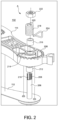
- embodiments of the present invention employ a system (shown in an exploded view of FIG. 2 ) to counteract the center of mass off-set of the equipment 302 and bring the bpm to an appropriate value, for example, 135 ⁇ 3 bpm.
- an appropriate value for example, 135 ⁇ 3 bpm.
- the system shown in FIG. 2 is an example of a mass balancing means for counter balancing the mass of an attached astronomical instrument. Other appropriate mass balancing means can be employed without deviating from the present invention.
- FIG. 2 provides an exploded view of a section of the mechanical tracking mount 102 identified by reference A in FIG. 1 , namely the system for counteracting the center of mass off-set of astronomical equipment mounted to the mechanical tracking mount 102, described above.
- the tracking arm 112 has bolt 206 provided on a side opposite to the mount bolt 108 and positioned coaxially with the mount bolt 108.
- the bolt 206 has a length sufficient to extend through a first bearing 212, a through hole 214 formed on the base member 114, a second bearing 216 and through a central hole of a coil torsion spring 218.
- Bearing 212 and bearing 216 can be any appropriate rotatable support means, such as ball bearings, roller bearings, or needle bearings as appropriate.
- bearing 212 and bearing 216 are needle bearings, since needle bearings can support greater loads than similarly sized ball bearings.
- the free end 208 of the bolt 206 is threaded and configured to receive nut 222.
- Nut 222 is sized to hold the tracking arm 112 to the base member 114.
- the bolt 206, first bearing 212, second bearing 216 and coil torsion spring 218 in combination are an example of a mass balancing means for balancing the mass of the astronomical equipment mounted on the holding means. Other mass balancing means can be substituted as appropriate without deviating from the present invention.
- the free end 208 of the bolt 206 includes a transverse channel 210 configured and dimensioned to receive and hold a crossbar 220 formed at a first end of the coil torsion spring 218.
- the second end of the coil torsion spring is formed into a selector structure 224 dimensioned to sit in one of a plurality of grooves defining castellations 226 formed along a semi-circular perimeter of the base member 114.
- the coil torsion spring 218 can be constructed of a resilient metal or metal alloy, such as, for example, carbon steel, stainless steel, etc.
- the torsion of the coil torsion spring 218 can be increased or decreased as desired. Specifically, increasing the torsion can have the effect of increasing the angular velocity of the tracking arm 112 for a given weight of a payload (e.g., astronomical equipment). Alternatively, increasing the torsion can result in driving a heavier payload at a same angular velocity as a lower torsion.
- a payload e.g., astronomical equipment
- embodiments of the present invention can track objects that move across the sky at a rate different than sidereal rate, for example, the moon, planets and other intra-solar system objects.
- the adjustable tension allows for a wide range of instrument weights that can be driven at an appropriate angular velocity.
- the castellations 226 allow for a simpler manufacturing process as well as reduced production cost.
- the castellations 226 can be integrally formed on the base member 114, which can allow for additive printing (e.g., 3D printing) to be used in the manufacture of the base member 114.
- the castellations 226 can be formed on the base member 114 by a milling process, which can be especially useful when fabricating the base member 114 from aluminum or other appropriate metal or metal alloy.
- the base member 114 can be manufactured using a casting process, in which the mold used includes features for forming the castellations 226 on the base member 114.
- usage of integrally formed castellations 226 also allows for greater precision in the placement of the grooves.
- one groove is positioned to correspond with a neutral point along the semi-circular perimeter of the base member 114 that does not impart tension on the coil torsion spring 218.
- a centrally positioned groove can correspond to the neutral point.
- the pair of bearings 212, 216 are installed on the bolt 206.
- the bearings 212, 216 can be needle bearings, which can eliminate backlash when tracking.
- less expensive bushings can be used in place of the bearings 212, 216.
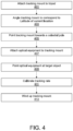
- FIG. 4 shows a procedure for using an embodiment of the present invention to track a celestial object.
- the tracking mount 102 is attached to a tripod.
- the tracking mount 102 is angled to match the latitude where the tracking mount 102 is set up, for example, approximately 41° North for New York City, at block 403.
- the tracking mount 102 is positioned so that the rotational axis of the tracking mount 102 is aligned with a celestial pole, such as near the star Polaris, which approximates the position of the north celestial pole (NCP), at block 405.
- the tracking mount 102 is now polar-aligned, meaning the rotation of a camera, for example, mounted on the tracking mount 102 will rotate in the same direction as the celestial sphere.
- the optical equipment is screwed onto the mount bolt 108. If a mount head 106 is attached to the mount bolt 108, the optical equipment can be attached to the mount head 106, instead.
- the optical equipment is pointed at a target object, at block 409.
- the tracking mount 102 is calibrated by moving the selector 224 from one groove to another groove of the castellations 226.
- a first test run can be executed with the selector 224 set to an arbitrary groove of the castellations 226, for example, setting the selector 224 to the center groove, which corresponds with the native bpm. Based on the results of the first test run, the selector 224 can be moved to a groove to the right (to accelerate) or left (to decelerate) of the arbitrary groove. The calibration can be carried out multiple times to arrive at an acceptable tracking rate.
- the correct balance can also be checked by turning the winding knob 110 clockwise and counterclockwise, if the force required to rotate winding knob 110 in both directions is similar, the balance offered by the spring will be correct.
- the winding knob 110 is fully rotated to wind up the timing assembly 504 at block 413 to track the target object.
- the timing assembly 504 is configured to move over a period of an hour, however, other embodiments can be configured to operate over other timing durations, such as 30 minutes, 2 hour, 5 hours, etc., for example. It should be noted that the loading of the timing assembly 504 at block 413 can cause a shift in the position of the optical instrument, necessitating re-aiming the optical instrument at the target object before imaging the target object.
- the winding knob 110 can be fully rotated, winding up the timing assembly, prior to executing the aiming at block 409. By preloading the timing assembly prior to aiming the optical equipment, and performing the calibration, a final re-aiming can be avoided.
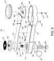
- the mechanical tracking mount 102 includes a support means, such as a base member 114, a tracking means, such as a tracking arm 112, a winding means, such as winding knob 110 and a holding means, such as a mounting bolt 108.
- the mounting bolt 108 is held onto a top surface of the tracking arm 112 by fastening means, such as bolts 521, for example.
- a protective material 513 such as a rubber or plastic mat, for example, can be placed to surround the mounting bolt 108.
- the protective material 513 provides a protective non-abrasive surface between the mechanical tracking mount 102 and the instrument or the mount head 106 shown in FIG. 1 .
- the tracking arm 112 can include a pair of adapter mounting bolts 604. The function of the adapter mounting bolts 604 will be described below with respect to FIG. 6 and FIG. 9 .
- a bolt shaft 206 extends from the mounting bolt 108 and is dimensioned to extend through a through hole formed in the tracking arm 112. Moreover, the bolt shaft 206 further extends through a through hole 214 formed in the base member 114.
- the bearing 212, the bearing 216, and the coil torsion spring 218 are placed on the bolt shaft 206 as well, such that the bolt shaft 206 extends through central through holes formed on the first bearing 212, the second bearing 216 and the coil torsion spring 218.
- bearing 212 and bearing 216 are needle bearings, since needle bearings can support greater loads than similarly sized ball bearings.
- the free end 208 of the bolt 206 is threaded and configured to receive nut 222. Nut 222 is sized to hold the tracking arm 112 to the base member 114.
- the free end 208 includes a transverse channel 210 configured and dimensioned to receive and hold a crossbar 220 formed at a first end of the coil torsion spring 218.
- the second end of the coil torsion spring 218 is formed into a selector structure 224 dimensioned to sit in one of a plurality of grooves formed as castellations 226 along a semi-circular perimeter of the base member 114, as described above with reference to FIG. 1 .
- the coil torsion spring 218 can be constructed of a resilient metal or metal alloy, such as, for example, carbon steel, stainless steel, etc.
- the torsion of the coil torsion spring 218 can be increased or decreased as desired. Specifically, increasing the torsion can have the effect of increasing the angular velocity of the tracking arm 112 for a given weight of a payload (e.g., astronomical equipment).
- a payload e.g., astronomical equipment
- embodiments of the present invention can track objects that move across the sky at a rate different than sidereal rate, for example, the moon, planets and other intra-solar system objects.
- the adjustable tension allows for a wide range of instrument weights that can be driven at an appropriate angular velocity.
- the castellations 226 allow for a simpler manufacturing process as well as reduced production cost.
- the castellations 226 can be integrally formed on the base member 114, which can allow for additive printing (e.g., 3D printing) to be used in the manufacture of the base member 114.
- the castellations 226 can be formed on the base member 114 by a milling process, which can be especially useful when fabricating the base member 114 from aluminum or other appropriate metal or metal alloy.
- the base member 114 can be manufactured using a casting process, in which the mold used includes features for forming the castellations 226 on the base member 114.
- usage of integrally formed castellations 226 also allows for greater precision in the placement of the grooves.
- one groove is positioned to correspond with a neutral point along the semi-circular perimeter of the base member 114 that does not impart tension on the coil torsion spring 218.
- a centrally positioned groove can correspond to the neutral point.
- a void 502 is formed on the surface of the base member 114.
- the void 502 can be formed as a circular, rectangular or elliptical void. In the present embodiment, the void 502 has a substantially elliptical shape.
- the void 502 is dimensioned to receive a mechanical timing means, such as a timing assembly 504, for example. As shown in FIG. 8 and FIG. 9 , the timing assembly 504 can be positioned at a first end of the void 502 or a second end of the void 502 depending on whether the mechanical tracking mount 102 is configured for operation in the northern hemisphere or the southern hemisphere.
- a bolt 515 and a washer 517 hold the timing assembly 504 within the void 502 of the base member 114.
- the timing assembly 504 includes an output shaft 506 on which is mounted a drive gear, such as gear 802 (shown in FIG. 8 ), for example.
- the gear 802 is configured to mesh with the teeth 508 of the tracking arm 112 as shown in FIG. 8 .
- the configuration shown in FIG. 8 can be used to track celestial bodies in the northern hemisphere.
- a configuration of the mechanical tracking mount 102 that can be used to track celestial bodies in the southern hemisphere is described below with reference to FIG. 6 and FIG. 9 .
- Protrusions 512 extend vertically from a top surface of the gear 802 and located at opposite sides of the output shaft 506.
- the output shaft 506 and the protrusions are held by features formed on a bottom surface of the winding knob 110.
- a set screw 804, shown in FIG. 8 can be provided to secure the winding knob 110 to the output shaft 506.
- the output shaft 506 is shown to have a hexagonal cross-section, however, other cross-sectional shapes (e.g., semicircular, circular, or rectangular, for example) can be used without deviating from the present invention.
- Turning the winding knob 110 applies a rotational force on the output shaft to wind a spiral torsion spring of the timing assembly 504. Additionally, when turning the winding knob 110 a rotational force is applied to the protrusions 512, which in turn rotates the gear 802 and advances the tracking arm to a start position.
- Indicia markings 550 on the surface of the base member 114 can be used to indicate time remaining before the tracking arm returns to its rest position, e.g., unwound position.
- a polar scope bracket 523 can be provided on the base member.
- the polar scope bracket 523 can be configured to hold a polar scope (not shown) in parallel alignment with the rotational axis of the tracking arm 112.
- a polar scope (not shown) in parallel alignment with the rotational axis of the tracking arm 112.
- the rotational axis of the tracking arm 112 should point to a region near Polaris (North Celestial Pole).
- the rotational axis of the tracking arm 112 should point to a region near Sigma Octantis (South Celestial Pole).
- a polar scope can greatly assist in precisely aligning the mechanical tracking mount 102 with the appropriate celestial pole.
- An alignment bolt 519 is provided that can be inserted into through-hole 560 formed on the base member 114 and extends through through-hole 562 formed on the tracking arm 112. When the tracking arm 112 is correctly aligned relative to the base member 114, the alignment bolt 519 will extend through through-hole 560 and through-hole 562. Proper alignment of the tracking arm 112 relative to the base member 114 provides consistent and predictable tracking periods.
- the alignment bolt 519 can be used as a locking means for locking the tracking arm 112 relative to the base member 114. Locking the tracking arm 112 can be useful for preventing unwanted movement of the tracking arm 112 during transport.
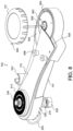
- FIG. 6 and FIG. 9 like components and structures are identified by like reference numerals, and thus, the descriptions provided above, with respect to FIG. 5 and FIG. 8 apply equally well to the structures shown in FIG. 6 and FIG. 9 .
- the previously described structures will not be described herein except as applicable for describing the distinguishing structures in FIG. 6 .
- FIG. 5 and FIG. 8 show an embodiment of the mechanical tracking mount 102 configured for tracking celestial bodies from the northern hemisphere.
- FIG. 6 and FIG. 9 show an embodiment of the mechanical tracking mount 102 configured for tracking celestial bodies from the southern hemisphere.
- the mechanical tracking mount 102 can be converted for operation from the southern hemisphere by the installation of a conversion plate 602.
- the conversion plate 602 includes a set of teeth 610 facing in an opposite direction relative to the teeth 508 of the tracking arm 112.
- the conversion plate 602 can be mounted to the tracking arm using the above-mentioned mounting bolts 604.
- the mounting bolts 604 can be inserted into through-holes 606 formed on the conversion plate 602.
- a pair of thumb nuts 608 can be used to secure the conversion plate 602 to the tracking arm 112.
- the thumb nuts 608 have textured or knurled perimeters to facilitate tool-less tightening and loosening of the thumb nuts 608.
- the mounting bolts 604 and thumb nuts 608 taken together are an example of a conversion plate holding means.
- Other means for holding the conversion plate 602 to the tracking arm 112, as known in the art, can be used in place of the mounting bolts 604 and thumb nuts 608 without deviating from the present invention.
- the timing assembly 504 may need to be shifted within the void 502 towards the rotational axis of the tracking arm 112.
- the teeth 508 of the tracking arm 112 mesh with the gear 802 at a first side, which causes the tracking arm to rotate counter-clockwise when the winding knob 110 is turned clockwise to wind the timing assembly 504.
- the tracking arm 112 then rotates clockwise when the timing assembly 504 unwinds.
- the teeth 610 of the conversion plate 602 mesh with the gear 802 from an opposite side.
- winding the timing assembly 504 by turning the winding knob 110 clockwise causes the conversion plate 602 and tracking arm 112 to rotate clockwise as well. Unwinding the timing assembly 504 causes the conversion plate 602 and tracking arm 112 to rotate counter-clockwise.
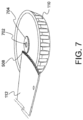
- FIG. 7 shows a winding knob 110 in accordance with another embodiment of the present invention.
- the winding knob 110 can include a gear 704 configured to mesh with teeth 508 of the tracking arm 112.
- the gear 802 shown in FIG. 8 and FIG. 9 is moved from the timing assembly 504 to an underside surface of the winding knob 110.
- a through-hole 702 is formed in the gear 704 at a center point and extends partially into the winding knob 110.
- the through-hole 702 is configured and dimensioned to receive an output shaft, such as the output shaft 506 of the timing assembly 504 shown in FIG. 5 , for example.
- such phrasing is intended to encompass the selection of the first listed option (A) only, or the selection of the second listed option (B) only, or the selection of the third listed option (C) only, or the selection of the first and the second listed options (A and B) only, or the selection of the first and third listed options (A and C) only, or the selection of the second and third listed options (B and C) only, or the selection of all three options (A and B and C).
- This may be extended for as many items listed.
Landscapes
- Physics & Mathematics (AREA)
- Engineering & Computer Science (AREA)
- General Engineering & Computer Science (AREA)
- General Physics & Mathematics (AREA)
- Mechanical Engineering (AREA)
- Optics & Photonics (AREA)
- Astronomy & Astrophysics (AREA)
- Telescopes (AREA)
Claims (15)
- Mechanische Nachführeinrichtung (102), die Folgendes umfasst:eine Vielzahl von Zinnen (226) in einer halbkreisförmigen Anordnung an einem ersten Ende eines Basiselements (114), wobei das Basiselement (114) ein Durchgangsloch (214) umfasst, das in einer radialen Mitte der Vielzahl von Zinnen (226) ausgebildet ist;einen Nachführarm (112) mit einem Schaft, der sich senkrecht zu einer langen Achse des Nachführarms (112) erstreckt, und einem Satz (610) von Zähnen (508), die in einer Position distal vom Schaft ausgebildet sind, wobei der Schaft eine Kerbe aufweist, die an einem Ende gegenüber dem Nachführarm (112) ausgebildet ist, wobei der Schaft dimensioniert ist, um in das Durchgangsloch (214) eingesetzt zu werden; undeine Spulentorsionsfeder (218) mit einer Querstrebe (220), die an einem Ende ausgebildet und dazu ausgelegt ist, in die Kerbe des Schafts zu passen, einer Auswählerstruktur (224), die an einem anderen Ende der Spulentorsionsfeder (218) ausgebildet ist, wobei die Auswählerstruktur (224) dimensioniert ist, um in einer Zinne (226) der Vielzahl von Zinnen (226) zu sitzen, wobei das Anpassen der Position der Auswählerstruktur (224) relativ zur Vielzahl von Zinnen (226) den Spulentorsionskoeffizienten der Spulentorsionsfeder (218) anpasst.
- Mechanische Nachführeinrichtung (102) nach Anspruch 1, die ferner eine Timinganordnung (504) umfasst, die dazu ausgelegt ist, den Nachführarm (112) über ein eingestelltes Zeitintervall von einer Startposition in eine Ruheposition zu drehen, wobei die Timinganordnung (504) in einer Position distal zu den Zinnen (226) am Basiselement (114) montiert ist.
- Mechanische Nachführeinrichtung (102) nach Anspruch 2, wobei die Timinganordnung (504) eine Spiraltorsionsfeder beinhaltet, die dazu ausgelegt ist, eine Drehbewegung auf eine Ausgangswelle (506) der Timinganordnung (504) auszuüben, wenn sie von einem aufgewickelten Zustand in einen abgewickelten Zustand geht.
- Mechanische Nachführeinrichtung (102) nach Anspruch 3, wobei die Timinganordnung (504) ein Zahnrad (802) beinhaltet, das an die Ausgangswelle (506) gekoppelt ist, wobei das Zahnrad (802) dazu ausgelegt ist, drehend in die Zähne (508) des Nachführarms (112) einzugreifen.
- Mechanische Nachführeinrichtung (102) nach Anspruch 3, wobei die Timinganordnung (504) einen Wickelknopf (110) beinhaltet, der an die Ausgangswelle (506) der Timinganordnung (504) gekoppelt ist, wobei der Wickelknopf (110) dazu ausgelegt ist, die Spiraltorsionsfeder zu wickeln.
- Mechanische Nachführeinrichtung (102) nach Anspruch 5, wobei der Wickelknopf (110) ein Zahnrad (704) beinhaltet, das an einer Fläche des Wickelknopfes (110) montiert, der Timinganordnung (504) zugewandt und dazu ausgelegt ist, in die Zähne (508) des Nachführarms (112) einzugreifen.
- Mechanische Nachführeinrichtung (102), die Folgendes umfasst:eine Vielzahl von Zinnen (226) in einer halbkreisförmigen Anordnung an einem ersten Ende eines Basiselements (114), wobei das Basiselement (114) ein Durchgangsloch (214) umfasst, das in einer radialen Mitte der Vielzahl von Zinnen (226) ausgebildet ist;einen Nachführarm (112) mit einem Satz (610) von Zähnen (508), die entlang einer Kante senkrecht zu einer langen Achse des Nachführarms (112) ausgebildet sind, wobei der Nachführarm (112) drehbar in der radialen Mitte der Vielzahl von Zinnen (226) gehalten wird; undeine Spulentorsionsfeder (218), die an einem ersten Ende verankert ist, wobei die Spulentorsionsfeder (218) eine Auswählerstruktur (224) beinhaltet, die an einem zweiten Ende der Spulentorsionsfeder (218) ausgebildet ist, wobei die Auswählerstruktur (224) dimensioniert ist, um in einer Zinne (226) der Vielzahl von Zinnen (226) zu sitzen.
- Mechanische Nachführeinrichtung (102) nach Anspruch 7, wobei das Anpassen der Position der Auswählerstruktur (224) relativ zur Vielzahl von Zinnen (226) den Torsionskoeffizienten der Spulentorsionsfeder (218) anpasst.
- Mechanische Nachführeinrichtung (102) nach Anspruch 7, die ferner eine Montageschraube (108) umfasst, die ein erstes Gewindeende aufweist, das dazu ausgelegt ist, eine astronomische Ausrüstung zu halten, wobei die Montageschraube (108) einen Schaft (206) beinhaltet, die dimensioniert ist, um sich durch ein Durchgangsloch zu erstrecken, das in einer Position entlang der langen Achse des Nachführarms (112) gegenüber dem Satz (610) von Zähnen (508) und das im Basiselement (114) ausgebildete Durchgangsloch zu erstrecken, wobei die Montageschraube (108) in einer Drehmitte des Nachführarms (112) befestigt ist;
wobei der Schaft (206) der Montageschraube (108) vorzugsweise eine Querkerbe beinhaltet, die dazu ausgelegt ist, das erste Ende der Spulentorsionsfeder (218) aufzunehmen und zu verankern, wobei sich der Schaft (206) durch den zentralen Hohlraum der Spulentorsionsfeder (218) erstreckt. - Mechanische Nachführeinrichtung (102) nach Anspruch 7, die ferner eine Timinganordnung (504) umfasst, die dazu ausgelegt ist, den Nachführarm (112) über ein eingestelltes Zeitintervall von einer Startposition in eine Ruheposition zu drehen, wobei die Timinganordnung (504) in einer Position distal zu den Zinnen (226) am Basiselement (114) montiert ist.
- Mechanische Nachführeinrichtung (102) nach Anspruch 10, wobei die Timinganordnung (504) eine Spiraltorsionsfeder beinhaltet, die dazu ausgelegt ist, eine Drehbewegung auf eine Ausgangswelle (506) der Timinganordnung (504) auszuüben, wenn sie von einem aufgewickelten Zustand in einen abgewickelten Zustand geht.
- Mechanische Nachführeinrichtung (102) nach Anspruch 11, wobei die Timinganordnung (504) ein Zahnrad beinhaltet, das an die Ausgangswelle (506) gekoppelt ist, wobei das Zahnrad dazu ausgelegt ist, drehend in den Satz (610) von Zähnen (508) des Nachführarms (112) einzugreifen und den Nachführarm (112) in eine Uhrzeigersinnrichtung zu drehen, wenn die Spiraltorsionsfeder abgewickelt wird.
- Mechanische Nachführeinrichtung (102) nach Anspruch 11, wobei die Timinganordnung (504) einen Wickelknopf (110) beinhaltet, der an die Ausgangswelle (506) der Timinganordnung (504) gekoppelt ist, wobei der Wickelknopf (110) dazu ausgelegt ist, die Spiraltorsionsfeder zu wickeln;
wobei der Wickelknopf (110) vorzugsweise ein Zahnrad beinhaltet, das an einer Fläche des Wickelknopfes (110) montiert, der Timinganordnung (504) zugewandt und dazu ausgelegt ist, in den Satz (610) von Zähnen (508) des Nachführarms (112) einzugreifen. - Mechanische Nachführeinrichtung (102) nach Anspruch 11, die ferner eine Umwandlungsplatte umfasst, die mit einem zweiten Satz (610) von Zähnen (508) ausgelegt ist, wobei die Umwandlungsplatte dazu ausgelegt ist, den Nachführarm (112) in eine Gegenuhrzeigersinnrichtung zu drehen, wenn die Spiraltorsionsfeder abgewickelt wird;
wobei die Timinganordnung (504) vorzugsweise ein Zahnrad beinhaltet, das an die Ausgangswelle (506) gekoppelt ist, wobei das Zahnrad dazu ausgelegt ist, drehend in den zweiten Satz (610) von Zähnen (508) der Umwandlungsplatte einzugreifen und den Nachführarm (112) in eine Uhrzeigersinnrichtung zu drehen, wenn die Spiraltorsionsfeder abgewickelt wird. - Mechanische Nachführeinrichtung (102) zum Nachführen von Himmelsobjekten durch eine darauf montierte astronomische Ausrüstung, wobei die mechanische Nachführeinrichtung (102) Folgendes umfasst:Haltemittel zum Halten einer astronomischen Ausrüstung;Masseausgleichsmittel zum Ausgleichen der Masse der astronomischen Ausrüstung, die von den Haltemitteln gehalten wird;Nachführmittel zum Drehen der astronomischen Ausrüstung synchron mit einer Drehung von Himmelsobjekten, die von der astronomischen Ausrüstung nachgeführt werden; undmechanische Timingmittel zum Erzeugen einer Drehung der Nachführmittel;wobei die mechanische Nachführeinrichtung (102) dadurch gekennzeichnet ist, dass entweder:die Masseausgleichsmittel eine Spulentorsionsfeder (218) beinhalten, die an einem ersten Ende verankert ist, wobei die Spulentorsionsfeder (218) eine Auswählerstruktur (224) aufweist, die an einem zweiten Ende der Spulentorsionsfeder (218) ausgebildet ist, wobei die Auswählerstruktur (224) dimensioniert ist, um in einer Zinne (226) einer Vielzahl von Zinnen (226) zu sitzen, die entlang einer Kante eines Basiselements (114) der mechanischen Nachführeinrichtung (102) als ein Halbkreis ausgebildet sind; oderdie Nachführmittel einen Nachführarm (112) beinhalten, der Nachführarm(112)-Bewegungsmittel aufweist, die an einem distalen Ende angeordnet sind, wobei der Nachführarm (112) an den Haltemitteln und den Masseausgleichsmitteln an einem proximalen Ende drehbar gesichert ist, wobei die Nachführarm(112)-Bewegungsmittel in ein Zahnrad eingreifen, das an eine Spiraltorsionsfeder der mechanischen Timingmittel gekoppelt ist.
Applications Claiming Priority (3)
| Application Number | Priority Date | Filing Date | Title |
|---|---|---|---|
| US202063112810P | 2020-11-12 | 2020-11-12 | |
| US17/518,787 US12135414B2 (en) | 2020-11-12 | 2021-11-04 | Mechanical tracking mount |
| PCT/EP2021/080758 WO2022101098A1 (en) | 2020-11-12 | 2021-11-05 | Mechanical tracking mount |
Publications (3)
| Publication Number | Publication Date |
|---|---|
| EP4244520A1 EP4244520A1 (de) | 2023-09-20 |
| EP4244520B1 true EP4244520B1 (de) | 2024-08-21 |
| EP4244520C0 EP4244520C0 (de) | 2024-08-21 |
Family
ID=81454359
Family Applications (1)
| Application Number | Title | Priority Date | Filing Date |
|---|---|---|---|
| EP21810294.5A Active EP4244520B1 (de) | 2020-11-12 | 2021-11-05 | Mechanische spurverfolgungshalterung |
Country Status (3)
| Country | Link |
|---|---|
| US (1) | US12135414B2 (de) |
| EP (1) | EP4244520B1 (de) |
| WO (1) | WO2022101098A1 (de) |
Families Citing this family (5)
| Publication number | Priority date | Publication date | Assignee | Title |
|---|---|---|---|---|
| TWI798097B (zh) * | 2022-05-31 | 2023-04-01 | 群光電子股份有限公司 | 連接組件 |
| IT202200025500A1 (it) * | 2022-12-13 | 2024-06-13 | Revolv Space B V | Gruppo cardanico rotativo per il controllo dell'orientamento di uno o più dispositivi orientabili di un sistema critico |
| CN219692865U (zh) * | 2023-04-23 | 2023-09-15 | 天津华来科技股份有限公司 | 悬臂机械结构及云台摄像头 |
| USD1076643S1 (en) * | 2024-08-09 | 2025-05-27 | Yuankun Chen | Mount |
| USD1072599S1 (en) * | 2024-11-08 | 2025-04-29 | Xiaojing Ye | Tripod mount adapter |
Family Cites Families (12)
| Publication number | Priority date | Publication date | Assignee | Title |
|---|---|---|---|---|
| JP2698028B2 (ja) * | 1992-09-30 | 1998-01-19 | 三菱電機株式会社 | ロボット |
| FR2728695B1 (fr) * | 1994-12-22 | 1997-03-28 | Aerospatiale | Dispositif de commande en rotation de grande precision, notamment pour telescope |
| JP3619786B2 (ja) * | 2001-03-26 | 2005-02-16 | 泰雄 土井 | 天体写真撮影用簡易型赤道儀 |
| GB2445959A (en) * | 2007-01-27 | 2008-07-30 | Richard James Taylor | Celestial tracking device |
| JP2009054976A (ja) * | 2007-08-27 | 2009-03-12 | Keishin Sakai | 太陽電池パネル用自動仰角追尾架台 |
| DE102009034144A1 (de) * | 2009-07-20 | 2011-06-22 | Gümpelein, Rudolf, 91567 | Nachführeinrichtung für eine Photovoltaikanlage |
| GB2485596A (en) * | 2010-11-20 | 2012-05-23 | Astrotrac Ltd | Self-guiding equatorial or altitude/azimuth telescope mount |
| US9945586B2 (en) * | 2011-09-21 | 2018-04-17 | The University Of Western Ontario | Solar tracker |
| CN102866496A (zh) * | 2012-10-18 | 2013-01-09 | 南京艾顿光电科技有限公司 | 平衡式赤道仪 |
| US10566926B2 (en) * | 2016-10-26 | 2020-02-18 | Craig Bradley Edward Wildman | Systems and methods for collecting solar energy using a parabolic trough solar collector |
| PT3589899T (pt) * | 2017-03-02 | 2023-03-29 | Array Tech Inc | Conjuntos de contrapeso por mola e seguidores solares incorporando conjuntos de contrapeso por mola |
| US10700634B2 (en) * | 2018-03-06 | 2020-06-30 | Utah State University | Mechanical solar tracker |
-
2021
- 2021-11-04 US US17/518,787 patent/US12135414B2/en active Active
- 2021-11-05 WO PCT/EP2021/080758 patent/WO2022101098A1/en not_active Ceased
- 2021-11-05 EP EP21810294.5A patent/EP4244520B1/de active Active
Also Published As
| Publication number | Publication date |
|---|---|
| US20220146810A1 (en) | 2022-05-12 |
| EP4244520C0 (de) | 2024-08-21 |
| WO2022101098A1 (en) | 2022-05-19 |
| EP4244520A1 (de) | 2023-09-20 |
| US12135414B2 (en) | 2024-11-05 |
Similar Documents
| Publication | Publication Date | Title |
|---|---|---|
| US12135414B2 (en) | Mechanical tracking mount | |
| US4682091A (en) | Telescope control system | |
| US4400066A (en) | Mounting and precision drive system for astronomical telescope, and the like | |
| US7642741B2 (en) | Handheld platform stabilization system employing distributed rotation sensors | |
| EP0849170A1 (de) | Verfahren und System zur Verringerung von mechanischen Störungen in Energiespeicher-Schwungrädern | |
| GB2485596A (en) | Self-guiding equatorial or altitude/azimuth telescope mount | |
| US20100109341A1 (en) | System and method for generating power using angular kinetic energy | |
| CN110296306B (zh) | 角度调节装置、传感器组件和无人驾驶汽车 | |
| US20010014213A1 (en) | Shake correcting apparatus | |
| EP0660911B1 (de) | Verbesserungen an kippbaren lastenträgern | |
| US20250060195A1 (en) | Archery bow sight support systems | |
| US3971620A (en) | Telescope assemblies | |
| US7382533B1 (en) | Disc based alt-azimuth telescope mount | |
| EP0700202B1 (de) | Vorrichtung zur Bildstabilisierung | |
| EP0698196A1 (de) | Bildaufnahmevorrichtung mit fernsteuerung | |
| CN112334698A (zh) | 竖向增稳机构、云台装置和感测设备 | |
| JP3619786B2 (ja) | 天体写真撮影用簡易型赤道儀 | |
| JP5463370B2 (ja) | 天測用調整具 | |
| CN222811497U (zh) | 一种俯仰调整机构及赤道仪 | |
| CN211014825U (zh) | 一种可调节观察角度的显微镜 | |
| GB2540409A (en) | Camera mount | |
| US4904071A (en) | Equatorial mounting system and drive therefor | |
| US20240085689A1 (en) | Hybrid mount for optical instrument | |
| WO2010089532A2 (en) | Wedge mount | |
| EP0796786A1 (de) | Verfahren und Vorrichtung für schnelle Betätigung von Nutzlasten an Bord einer Raumplattform |
Legal Events
| Date | Code | Title | Description |
|---|---|---|---|
| STAA | Information on the status of an ep patent application or granted ep patent |
Free format text: STATUS: UNKNOWN |
|
| STAA | Information on the status of an ep patent application or granted ep patent |
Free format text: STATUS: THE INTERNATIONAL PUBLICATION HAS BEEN MADE |
|
| PUAI | Public reference made under article 153(3) epc to a published international application that has entered the european phase |
Free format text: ORIGINAL CODE: 0009012 |
|
| STAA | Information on the status of an ep patent application or granted ep patent |
Free format text: STATUS: REQUEST FOR EXAMINATION WAS MADE |
|
| 17P | Request for examination filed |
Effective date: 20230516 |
|
| AK | Designated contracting states |
Kind code of ref document: A1 Designated state(s): AL AT BE BG CH CY CZ DE DK EE ES FI FR GB GR HR HU IE IS IT LI LT LU LV MC MK MT NL NO PL PT RO RS SE SI SK SM TR |
|
| DAV | Request for validation of the european patent (deleted) | ||
| DAX | Request for extension of the european patent (deleted) | ||
| GRAP | Despatch of communication of intention to grant a patent |
Free format text: ORIGINAL CODE: EPIDOSNIGR1 |
|
| STAA | Information on the status of an ep patent application or granted ep patent |
Free format text: STATUS: GRANT OF PATENT IS INTENDED |
|
| INTG | Intention to grant announced |
Effective date: 20240229 |
|
| GRAJ | Information related to disapproval of communication of intention to grant by the applicant or resumption of examination proceedings by the epo deleted |
Free format text: ORIGINAL CODE: EPIDOSDIGR1 |
|
| STAA | Information on the status of an ep patent application or granted ep patent |
Free format text: STATUS: REQUEST FOR EXAMINATION WAS MADE |
|
| GRAP | Despatch of communication of intention to grant a patent |
Free format text: ORIGINAL CODE: EPIDOSNIGR1 |
|
| STAA | Information on the status of an ep patent application or granted ep patent |
Free format text: STATUS: GRANT OF PATENT IS INTENDED |
|
| GRAS | Grant fee paid |
Free format text: ORIGINAL CODE: EPIDOSNIGR3 |
|
| GRAA | (expected) grant |
Free format text: ORIGINAL CODE: 0009210 |
|
| STAA | Information on the status of an ep patent application or granted ep patent |
Free format text: STATUS: THE PATENT HAS BEEN GRANTED |
|
| INTC | Intention to grant announced (deleted) | ||
| INTG | Intention to grant announced |
Effective date: 20240716 |
|
| AK | Designated contracting states |
Kind code of ref document: B1 Designated state(s): AL AT BE BG CH CY CZ DE DK EE ES FI FR GB GR HR HU IE IS IT LI LT LU LV MC MK MT NL NO PL PT RO RS SE SI SK SM TR |
|
| REG | Reference to a national code |
Ref country code: GB Ref legal event code: FG4D |
|
| REG | Reference to a national code |
Ref country code: CH Ref legal event code: EP |
|
| REG | Reference to a national code |
Ref country code: IE Ref legal event code: FG4D |
|
| REG | Reference to a national code |
Ref country code: DE Ref legal event code: R096 Ref document number: 602021017669 Country of ref document: DE |
|
| U01 | Request for unitary effect filed |
Effective date: 20240912 |
|
| U07 | Unitary effect registered |
Designated state(s): AT BE BG DE DK EE FI FR IT LT LU LV MT NL PT RO SE SI Effective date: 20241004 |
|
| U20 | Renewal fee for the european patent with unitary effect paid |
Year of fee payment: 4 Effective date: 20241127 |
|
| PG25 | Lapsed in a contracting state [announced via postgrant information from national office to epo] |
Ref country code: NO Free format text: LAPSE BECAUSE OF FAILURE TO SUBMIT A TRANSLATION OF THE DESCRIPTION OR TO PAY THE FEE WITHIN THE PRESCRIBED TIME-LIMIT Effective date: 20241121 |
|
| PG25 | Lapsed in a contracting state [announced via postgrant information from national office to epo] |
Ref country code: PL Free format text: LAPSE BECAUSE OF FAILURE TO SUBMIT A TRANSLATION OF THE DESCRIPTION OR TO PAY THE FEE WITHIN THE PRESCRIBED TIME-LIMIT Effective date: 20240821 Ref country code: GR Free format text: LAPSE BECAUSE OF FAILURE TO SUBMIT A TRANSLATION OF THE DESCRIPTION OR TO PAY THE FEE WITHIN THE PRESCRIBED TIME-LIMIT Effective date: 20241122 |
|
| PG25 | Lapsed in a contracting state [announced via postgrant information from national office to epo] |
Ref country code: IS Free format text: LAPSE BECAUSE OF FAILURE TO SUBMIT A TRANSLATION OF THE DESCRIPTION OR TO PAY THE FEE WITHIN THE PRESCRIBED TIME-LIMIT Effective date: 20241221 |
|
| PG25 | Lapsed in a contracting state [announced via postgrant information from national office to epo] |
Ref country code: HR Free format text: LAPSE BECAUSE OF FAILURE TO SUBMIT A TRANSLATION OF THE DESCRIPTION OR TO PAY THE FEE WITHIN THE PRESCRIBED TIME-LIMIT Effective date: 20240821 |
|
| PG25 | Lapsed in a contracting state [announced via postgrant information from national office to epo] |
Ref country code: ES Free format text: LAPSE BECAUSE OF FAILURE TO SUBMIT A TRANSLATION OF THE DESCRIPTION OR TO PAY THE FEE WITHIN THE PRESCRIBED TIME-LIMIT Effective date: 20240821 Ref country code: RS Free format text: LAPSE BECAUSE OF FAILURE TO SUBMIT A TRANSLATION OF THE DESCRIPTION OR TO PAY THE FEE WITHIN THE PRESCRIBED TIME-LIMIT Effective date: 20241121 |
|
| PG25 | Lapsed in a contracting state [announced via postgrant information from national office to epo] |
Ref country code: RS Free format text: LAPSE BECAUSE OF FAILURE TO SUBMIT A TRANSLATION OF THE DESCRIPTION OR TO PAY THE FEE WITHIN THE PRESCRIBED TIME-LIMIT Effective date: 20241121 Ref country code: PL Free format text: LAPSE BECAUSE OF FAILURE TO SUBMIT A TRANSLATION OF THE DESCRIPTION OR TO PAY THE FEE WITHIN THE PRESCRIBED TIME-LIMIT Effective date: 20240821 Ref country code: NO Free format text: LAPSE BECAUSE OF FAILURE TO SUBMIT A TRANSLATION OF THE DESCRIPTION OR TO PAY THE FEE WITHIN THE PRESCRIBED TIME-LIMIT Effective date: 20241121 Ref country code: IS Free format text: LAPSE BECAUSE OF FAILURE TO SUBMIT A TRANSLATION OF THE DESCRIPTION OR TO PAY THE FEE WITHIN THE PRESCRIBED TIME-LIMIT Effective date: 20241221 Ref country code: HR Free format text: LAPSE BECAUSE OF FAILURE TO SUBMIT A TRANSLATION OF THE DESCRIPTION OR TO PAY THE FEE WITHIN THE PRESCRIBED TIME-LIMIT Effective date: 20240821 Ref country code: GR Free format text: LAPSE BECAUSE OF FAILURE TO SUBMIT A TRANSLATION OF THE DESCRIPTION OR TO PAY THE FEE WITHIN THE PRESCRIBED TIME-LIMIT Effective date: 20241122 Ref country code: ES Free format text: LAPSE BECAUSE OF FAILURE TO SUBMIT A TRANSLATION OF THE DESCRIPTION OR TO PAY THE FEE WITHIN THE PRESCRIBED TIME-LIMIT Effective date: 20240821 |
|
| PG25 | Lapsed in a contracting state [announced via postgrant information from national office to epo] |
Ref country code: SM Free format text: LAPSE BECAUSE OF FAILURE TO SUBMIT A TRANSLATION OF THE DESCRIPTION OR TO PAY THE FEE WITHIN THE PRESCRIBED TIME-LIMIT Effective date: 20240821 |
|
| PG25 | Lapsed in a contracting state [announced via postgrant information from national office to epo] |
Ref country code: CZ Free format text: LAPSE BECAUSE OF FAILURE TO SUBMIT A TRANSLATION OF THE DESCRIPTION OR TO PAY THE FEE WITHIN THE PRESCRIBED TIME-LIMIT Effective date: 20240821 |
|
| PG25 | Lapsed in a contracting state [announced via postgrant information from national office to epo] |
Ref country code: SK Free format text: LAPSE BECAUSE OF FAILURE TO SUBMIT A TRANSLATION OF THE DESCRIPTION OR TO PAY THE FEE WITHIN THE PRESCRIBED TIME-LIMIT Effective date: 20240821 |
|
| PLBE | No opposition filed within time limit |
Free format text: ORIGINAL CODE: 0009261 |
|
| STAA | Information on the status of an ep patent application or granted ep patent |
Free format text: STATUS: NO OPPOSITION FILED WITHIN TIME LIMIT |
|
| REG | Reference to a national code |
Ref country code: CH Ref legal event code: PL |
|
| PG25 | Lapsed in a contracting state [announced via postgrant information from national office to epo] |
Ref country code: MC Free format text: LAPSE BECAUSE OF FAILURE TO SUBMIT A TRANSLATION OF THE DESCRIPTION OR TO PAY THE FEE WITHIN THE PRESCRIBED TIME-LIMIT Effective date: 20240821 |
|
| REG | Reference to a national code |
Ref country code: CH Ref legal event code: PL |
|
| PG25 | Lapsed in a contracting state [announced via postgrant information from national office to epo] |
Ref country code: CH Free format text: LAPSE BECAUSE OF NON-PAYMENT OF DUE FEES Effective date: 20241130 |
|
| 26N | No opposition filed |
Effective date: 20250522 |
|
| PG25 | Lapsed in a contracting state [announced via postgrant information from national office to epo] |
Ref country code: IE Free format text: LAPSE BECAUSE OF NON-PAYMENT OF DUE FEES Effective date: 20241105 |
|
| U20 | Renewal fee for the european patent with unitary effect paid |
Year of fee payment: 5 Effective date: 20251021 |
|
| PG25 | Lapsed in a contracting state [announced via postgrant information from national office to epo] |
Ref country code: HU Free format text: LAPSE BECAUSE OF FAILURE TO SUBMIT A TRANSLATION OF THE DESCRIPTION OR TO PAY THE FEE WITHIN THE PRESCRIBED TIME-LIMIT; INVALID AB INITIO Effective date: 20211105 |
|
| PG25 | Lapsed in a contracting state [announced via postgrant information from national office to epo] |
Ref country code: CY Free format text: LAPSE BECAUSE OF FAILURE TO SUBMIT A TRANSLATION OF THE DESCRIPTION OR TO PAY THE FEE WITHIN THE PRESCRIBED TIME-LIMIT; INVALID AB INITIO Effective date: 20211105 |