EP4244510B1 - Valve system with improved sealing - Google Patents
Valve system with improved sealing Download PDFInfo
- Publication number
- EP4244510B1 EP4244510B1 EP21801510.5A EP21801510A EP4244510B1 EP 4244510 B1 EP4244510 B1 EP 4244510B1 EP 21801510 A EP21801510 A EP 21801510A EP 4244510 B1 EP4244510 B1 EP 4244510B1
- Authority
- EP
- European Patent Office
- Prior art keywords
- stuffing box
- valve body
- valve
- shoulder
- groove
- Prior art date
- Legal status (The legal status is an assumption and is not a legal conclusion. Google has not performed a legal analysis and makes no representation as to the accuracy of the status listed.)
- Active
Links
Images



Classifications
-
- F—MECHANICAL ENGINEERING; LIGHTING; HEATING; WEAPONS; BLASTING
- F16—ENGINEERING ELEMENTS AND UNITS; GENERAL MEASURES FOR PRODUCING AND MAINTAINING EFFECTIVE FUNCTIONING OF MACHINES OR INSTALLATIONS; THERMAL INSULATION IN GENERAL
- F16K—VALVES; TAPS; COCKS; ACTUATING-FLOATS; DEVICES FOR VENTING OR AERATING
- F16K41/00—Spindle sealings
- F16K41/02—Spindle sealings with stuffing-box ; Sealing rings
- F16K41/04—Spindle sealings with stuffing-box ; Sealing rings with at least one ring of rubber or like material between spindle and housing
-
- F—MECHANICAL ENGINEERING; LIGHTING; HEATING; WEAPONS; BLASTING
- F16—ENGINEERING ELEMENTS AND UNITS; GENERAL MEASURES FOR PRODUCING AND MAINTAINING EFFECTIVE FUNCTIONING OF MACHINES OR INSTALLATIONS; THERMAL INSULATION IN GENERAL
- F16K—VALVES; TAPS; COCKS; ACTUATING-FLOATS; DEVICES FOR VENTING OR AERATING
- F16K27/00—Construction of housing; Use of materials therefor
- F16K27/02—Construction of housing; Use of materials therefor of lift valves
-
- F—MECHANICAL ENGINEERING; LIGHTING; HEATING; WEAPONS; BLASTING
- F16—ENGINEERING ELEMENTS AND UNITS; GENERAL MEASURES FOR PRODUCING AND MAINTAINING EFFECTIVE FUNCTIONING OF MACHINES OR INSTALLATIONS; THERMAL INSULATION IN GENERAL
- F16K—VALVES; TAPS; COCKS; ACTUATING-FLOATS; DEVICES FOR VENTING OR AERATING
- F16K41/00—Spindle sealings
-
- F—MECHANICAL ENGINEERING; LIGHTING; HEATING; WEAPONS; BLASTING
- F16—ENGINEERING ELEMENTS AND UNITS; GENERAL MEASURES FOR PRODUCING AND MAINTAINING EFFECTIVE FUNCTIONING OF MACHINES OR INSTALLATIONS; THERMAL INSULATION IN GENERAL
- F16K—VALVES; TAPS; COCKS; ACTUATING-FLOATS; DEVICES FOR VENTING OR AERATING
- F16K41/00—Spindle sealings
- F16K41/02—Spindle sealings with stuffing-box ; Sealing rings
Definitions
- the present invention is related to a valve system, and more particularly but not exclusively to a pressure actuated fluid valve system.
- a type of commonly used valve system as shown in Figs.1A , comprises a valve body 20 housing a plunger 40 fixed at one end to a reciprocating valve stem 50. The latter extends at the other end into a top box (not shown) of the valve system.
- the top box may comprise actuating means for controlling the reciprocating movement of the stem 50.
- the valve system further comprises a stuffing box 30 fixed to the valve body 20 and housing an annular packing 60 for sealing the stem 50.
- a sealing element 15 for preventing liquid leakage between the stuffing box and valve body commonly made of polytetrafluoroethylene (PTFE) is received in an annular cavity 80 formed between the stuffing box and the valve body as shown in Fig.1B .
- PTFE polytetrafluoroethylene
- the sealing element 15 is compressed essentially in the axial direction by the stuffing box 30.
- This construction requires a relatively high screwing torque for compressing the sealing element 15 due to the large contact area between the latter and the stuffing box 30.
- the fluid 87 is not prevented to enter the space between the sealing element 15 and the stuffing box 30 on the radially inner side of the sealing element, as shown. Therefore, the pressure of the fluid 87 may cause in some situations the sealing element 15 to flow into an axial gap 84 between the valve body 20 and the stuffing box 30. This may lead to a possibility of leakage over a time due to stress relief of the sealing element 15 caused by this deformation of the sealing element.
- the seal relaxation may also result in thread loosening between the stuffing box 30 and the valve body 20.
- DE4042035 discloses a sealing arrangement on a spindle of a valve.
- the arrangement comprises a stuffing box arranged between a collar threaded thereto and a flange of a valve body.
- the stuffing box comprises recesses forming respectively with the flange and the collar a cavity for receiving a sealing element.
- the cavities also require relatively high screwing torque for compressing the sealing elements due to the large contact area between the latter and the stuffing box.
- Exemplary embodiments of the present invention relate to a valve system according to claim 1, the valve system comprising a valve body and a stuffing box assembled to the valve body, the valve body having an internal surface defining an annular groove, this annular groove having an upper side, a lower side and a bottom extending axially between the upper and lower sides, the annular groove forming with the stuffing box an annular cavity for receiving a sealing element.
- upper and lower refer to the relative position along a longitudinal axis of the system oriented vertically, with the stuffing box lying above the valve body.
- the sealing element is at least partially received in the groove. Accordingly, the part of the sealing element received in the groove is not axially compressed by the stuffing box. Thus, due to the reduced contact area between the stuffing box and the sealing element, the assembly needs lower screwing torque for sealing. In this way, the sealing element may be more easily caused to expend radially against the stuffing box and the valve body and create corresponding sealing surfaces. A flow of fluid at the interface between the sealing element and the stuffing box and over the entire height of the sealing element may be more easily avoided.
- the groove may have a depth of at least 1mm.
- a shoulder of the internal surface of the valve body defining the lower side of the groove may come in axial abutment with the stuffing box.
- the stuffing box comprises a first and a second shoulder.
- the first shoulder comes in axial contact with the sealing element.
- the second shoulder may be in axial abutment with the shoulder of the valve body defining the lower side of the groove.
- the stuffing box may comprise a surface, preferably cylindrical, extending axially between the first and second shoulders, configured for coming in radial contact with the sealing element.
- the valve system comprises a plunger housed in the valve body; this plunger may be fixed at one end to a reciprocating valve stem.
- the valve may comprise a first interface extending axially between the valve body and the stuffing box, situated axially farther from the plunger than the annular groove.
- the first interface may be located at a distance from the longitudinal axis of the system, that is smaller than the distance from which the bottom of the groove is spaced from said axis, but preferably larger than the distance by which the surface extending axially between the first and second shoulders is spaced from said axis.
- the valve may comprise a second interface extending axially between the valve body and the stuffing box, situated axially closer to the plunger than the annular groove.
- the second interface may be located at a distance from the longitudinal axis of the system that is smaller than the distance by which the surface extending axially between the first and second shoulders is spaced from said axis.
- the stuffing box is preferably assembled to the valve body by screwing and the valve system comprises corresponding threads on the stuffing box and the valve body.
- the annular cavity is preferably located closer to the plunger than said threads, when observed along a longitudinal axis of the valve system. The sealing element thus avoids the fluid to flow into the threads.
- the sealing element may comprise or be composed of PTFE.
- the valve system may be a pressure actuated valve system, or motor actuated valve.
- Exemplary embodiments of the present invention also relate to a method for assembling a valve body and a stuffing box of a valve system of claim 1, the stuffing box comprising a collar in contact with a top surface of the valve body, the method comprising deforming the stuffing box during assembly thereof to the valve body, preferably by screwing, so that the height by which the collar protrudes is decreased after assembly.
- the invention allows forming a smoother surface at the joint line between the stuffing box and the valve body, without leaving any substantial retention area at the joint line.
- valve system thus obtained may not comprise any acute or right angle between the top surface of the valve body and a top surface of the collar.
- Exemplary embodiments of the present invention also relate to a method for assembling a valve body and a stuffing box of a valve system of claim 1, the valve body being assembled to the stuffing box by screwing, the valve body having an internal surface defining an annular groove, this annular groove having an upper side, a lower side and a bottom extending axially between the upper and lower sides, the annular groove forming with the stuffing box an annular cavity for receiving a sealing element, the stuffing box comprising a collar in contact with a top surface of the valve body, the method comprising deforming the stuffing box during assembly thereof to the valve body, so that the height by which the collar protrudes is decreased after assembly.
- valve system obtained after assembly exhibits all or part of the features of the valve system mentioned above.
- the method may comprise a first step of positioning the collar of the stuffing box on the top surface of the valve body, while keeping an axial gap between the lower side of the annular groove and the stuffing box, in particular between the lower side of the annular groove and the second shoulder thereof.
- the method may comprise a second step of mechanically deforming the collar of the stuffing box, in particular due to screwing during the assembly, until the lower side of the annular groove comes into contact with the stuffing box, in particular until the shoulder of the valve body defining the lower side of the annular groove comes into contact with the second shoulder.
- Exemplary embodiments of the present invention also discloses a valve system, comprising a valve body and a stuffing box assembled to the valve body by screwing, the stuffing box comprising a collar in contact with a top surface of the valve body, the collar of the stuffing box being deformed during assembly thereof to the valve body.
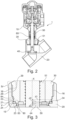
- a valve system 1 of the invention as shown in Fig.2 , comprises a valve body 20 and a top box 10.
- the valve body 20 houses a plunger 40 fixed to a reciprocating stem 50 at one end.
- the opposite end of the reciprocating stem 50 extends into the top box 10, which comprises an actuator for controlling the up and down movement of the stem 50 along the longitudinal axis X of the system, thus the opening and closing of the valve by the plunger 40.
- a stuffing box 30 is screwed to the valve body 20 via cooperating threads 16, situated respectively on an internal surface 29 of the valve body 20 and an external surface 39 of the stuffing box 30.
- the stuffing box 30 comprises a central bore 51 inside which the stem 50 may slide.
- a top surface 38 of the collar 37 forms a smooth joint line 8 with an adjacent top surface 28 of the valve body 20, without the presence of any substantial acute- or right-angle external protrusion between the top surfaces 28 and 38. In this way, there is no substantial retention area created at the joint line 8, which helps to avoid accumulation of undesired substances therein.
- the valve body 20 comprises an annular groove 21 on its internal surface 29.
- the annular groove 21 comprises a bottom 24, an upper side 22 and a lower side 23.
- the bottom 24 of the annular groove 21 extends axially between the upper and lower sides 22, 23.
- the lower side 23 is defined by a shoulder 98 of the valve body.
- the annular groove 21 preferably has a depth d, measured in a direction parallel to a radial direction of the valve system, which is at least of 1mm.
- the annular groove 21 has a height h , measured in a direction parallel to the longitudinal axis X of the valve system, that is preferably of between 2 and 5 mm.
- the shoulder 98 has a width w 1 preferably of between 2mm and 10mm when measured radially.
- the stuffing box 30, as shown in Fig.5 and 5B comprises on its external surface 39 a first shoulder 45 and a second shoulder 46.
- the first shoulder 45 is configured for coming in axial contact with the sealing element 15.
- the second shoulder 46 is in axial abutment with the shoulder 98 defining lower side 23 of the groove 21.
- the first and second shoulders are separated by a cylindrical surface 34 extending axially.
- the first shoulder 45 may have a width w 2 of between 2mm and 10mm.
- the second shoulder 46 may have a width w 3 of between 2mm and 10mm.
- the annular cavity 80 is located closer to the plunger 40 than the threads 16, when observed in the longitudinal direction X of the valve system.
- the valve system comprises a first interface 84 between the stuffing box 30 and the valve body 20 that is situated farther to the plunger 40 than the annular cavity 80. As can be seen in Fig.5 , the first interface 84 is radially inner to the bottom 24 of the groove 21.
- the valve system comprises a second interface 83 between the stuffing box 30 and the valve body 20 that is situated axially closer to the plunger 40 than the annular cavity 80.
- the second interface 83 is radially inner to the surface 34.
- the stuffing box 30 is screwed into the valve body until the collar 27 comes into abutment with the top surface 28 of valve body 20, as shown in Fig.6 and Fig.7 .
- an axial gap 99 of a height h ' is then existing between the lower side 23 of the groove 21 and the shoulder 46.
- the height h by which the collar 37 protrudes from the top surface 28 is decreased, substantially to a value of less than 1mm. In this way, there is no pronounced discontinuity between the top surface 28 of the valve body 20 and the top surface 38 of the collar 37, which helps avoid accumulation of undesired material in the zone around the joint line 8.
- the shoulder 98 of the valve body comes into abutment with the second shoulder 46 of the stuffing box 20, so that the sealing element 15 is axially compressed by the first shoulder 45 and the shoulder 98 and expands radially.
- sealing interfaces are thus formed, respectively between the sealing element 15 and the bottom 24, between the sealing element 15 and the lower side 23, between the sealing element 15 and the cylindrical surface 34, and between the sealing element 15 and the first shoulder 45.
- the stuffing box 30 does not axially compress the sealing element 15 on its portion which is received in the annular groove 21.
- the first shoulder 45 is axially closer to the lower side 23 than is the upper side 22 of the annular groove 21.
- a ratio l / h between the distance l from the first shoulder 45 to the lower side 23 and the height h of the annular groove 21, is preferably between 0.5 and 0.9.
- the ratio between the depth d of the groove 21 and the width w 2 of the first shoulder 45, i.e. d / w 2 is preferably at least 2.
Landscapes
- Engineering & Computer Science (AREA)
- General Engineering & Computer Science (AREA)
- Mechanical Engineering (AREA)
- Lift Valve (AREA)
- Valve Housings (AREA)
Description
- The present invention is related to a valve system, and more particularly but not exclusively to a pressure actuated fluid valve system.
- A type of commonly used valve system, as shown in
Figs.1A , comprises avalve body 20 housing aplunger 40 fixed at one end to a reciprocatingvalve stem 50. The latter extends at the other end into a top box (not shown) of the valve system. The top box may comprise actuating means for controlling the reciprocating movement of thestem 50. - The valve system further comprises a
stuffing box 30 fixed to thevalve body 20 and housing anannular packing 60 for sealing thestem 50. - In currently known systems, the
stuffing box 30, after being threaded to thevalve body 20, forms a visible protrusion P on the outside surface of thevalve body 20, where dirt and alike may accumulate, which is not desirable in view of the general requirements of some industries such as the food and hygiene industries. - Furthermore, in known products, a
sealing element 15 for preventing liquid leakage between the stuffing box and valve body, commonly made of polytetrafluoroethylene (PTFE), is received in anannular cavity 80 formed between the stuffing box and the valve body as shown inFig.1B . - In such a construction, the
sealing element 15 is compressed essentially in the axial direction by thestuffing box 30. This construction requires a relatively high screwing torque for compressing the sealingelement 15 due to the large contact area between the latter and thestuffing box 30. Furthermore, since the sealingelement 15 is little compressed or not compressed in the radial direction, thefluid 87 is not prevented to enter the space between thesealing element 15 and thestuffing box 30 on the radially inner side of the sealing element, as shown. Therefore, the pressure of thefluid 87 may cause in some situations the sealingelement 15 to flow into anaxial gap 84 between thevalve body 20 and thestuffing box 30. This may lead to a possibility of leakage over a time due to stress relief of the sealingelement 15 caused by this deformation of the sealing element. The seal relaxation may also result in thread loosening between thestuffing box 30 and thevalve body 20. -
DE4042035 discloses a sealing arrangement on a spindle of a valve. The arrangement comprises a stuffing box arranged between a collar threaded thereto and a flange of a valve body. The stuffing box comprises recesses forming respectively with the flange and the collar a cavity for receiving a sealing element. InDE 4042035 , the cavities also require relatively high screwing torque for compressing the sealing elements due to the large contact area between the latter and the stuffing box. -
- There exists a need to further improve existing valve systems and to remedy at least in part to the drawbacks mentioned above.
- Exemplary embodiments of the present invention relate to a valve system according to
claim 1, the valve system comprising a valve body and a stuffing box assembled to the valve body, the valve body having an internal surface defining an annular groove, this annular groove having an upper side, a lower side and a bottom extending axially between the upper and lower sides, the annular groove forming with the stuffing box an annular cavity for receiving a sealing element. - The terms "upper" and "lower" refer to the relative position along a longitudinal axis of the system oriented vertically, with the stuffing box lying above the valve body.
- In the present invention, the sealing element is at least partially received in the groove. Accordingly, the part of the sealing element received in the groove is not axially compressed by the stuffing box. Thus, due to the reduced contact area between the stuffing box and the sealing element, the assembly needs lower screwing torque for sealing. In this way, the sealing element may be more easily caused to expend radially against the stuffing box and the valve body and create corresponding sealing surfaces. A flow of fluid at the interface between the sealing element and the stuffing box and over the entire height of the sealing element may be more easily avoided.
- The groove may have a depth of at least 1mm.
- A shoulder of the internal surface of the valve body defining the lower side of the groove may come in axial abutment with the stuffing box.
- The stuffing box comprises a first and a second shoulder.
- The first shoulder comes in axial contact with the sealing element.
- The second shoulder may be in axial abutment with the shoulder of the valve body defining the lower side of the groove.
- The stuffing box may comprise a surface, preferably cylindrical, extending axially between the first and second shoulders, configured for coming in radial contact with the sealing element.
- Preferably, the valve system comprises a plunger housed in the valve body; this plunger may be fixed at one end to a reciprocating valve stem.
- The valve may comprise a first interface extending axially between the valve body and the stuffing box, situated axially farther from the plunger than the annular groove. The first interface may be located at a distance from the longitudinal axis of the system, that is smaller than the distance from which the bottom of the groove is spaced from said axis, but preferably larger than the distance by which the surface extending axially between the first and second shoulders is spaced from said axis.
- The valve may comprise a second interface extending axially between the valve body and the stuffing box, situated axially closer to the plunger than the annular groove. The second interface may be located at a distance from the longitudinal axis of the system that is smaller than the distance by which the surface extending axially between the first and second shoulders is spaced from said axis.
- The stuffing box is preferably assembled to the valve body by screwing and the valve system comprises corresponding threads on the stuffing box and the valve body. The annular cavity is preferably located closer to the plunger than said threads, when observed along a longitudinal axis of the valve system. The sealing element thus avoids the fluid to flow into the threads.
- The sealing element may comprise or be composed of PTFE.
- The valve system may be a pressure actuated valve system, or motor actuated valve.
- Exemplary embodiments of the present invention also relate to a method for assembling a valve body and a stuffing box of a valve system of
claim 1, the stuffing box comprising a collar in contact with a top surface of the valve body, the method comprising deforming the stuffing box during assembly thereof to the valve body, preferably by screwing, so that the height by which the collar protrudes is decreased after assembly. - By deforming said collar during assembly, the invention allows forming a smoother surface at the joint line between the stuffing box and the valve body, without leaving any substantial retention area at the joint line.
- In particular, the valve system thus obtained may not comprise any acute or right angle between the top surface of the valve body and a top surface of the collar.
- Exemplary embodiments of the present invention also relate to a method for assembling a valve body and a stuffing box of a valve system of
claim 1, the valve body being assembled to the stuffing box by screwing, the valve body having an internal surface defining an annular groove, this annular groove having an upper side, a lower side and a bottom extending axially between the upper and lower sides, the annular groove forming with the stuffing box an annular cavity for receiving a sealing element, the stuffing box comprising a collar in contact with a top surface of the valve body, the method comprising deforming the stuffing box during assembly thereof to the valve body, so that the height by which the collar protrudes is decreased after assembly. - The valve system obtained after assembly exhibits all or part of the features of the valve system mentioned above.
- The method may comprise a first step of positioning the collar of the stuffing box on the top surface of the valve body, while keeping an axial gap between the lower side of the annular groove and the stuffing box, in particular between the lower side of the annular groove and the second shoulder thereof.
- The method may comprise a second step of mechanically deforming the collar of the stuffing box, in particular due to screwing during the assembly, until the lower side of the annular groove comes into contact with the stuffing box, in particular until the shoulder of the valve body defining the lower side of the annular groove comes into contact with the second shoulder.
- Exemplary embodiments of the present invention also discloses a valve system, comprising a valve body and a stuffing box assembled to the valve body by screwing, the stuffing box comprising a collar in contact with a top surface of the valve body, the collar of the stuffing box being deformed during assembly thereof to the valve body.
- Embodiments of the invention will now be described in some further detail with reference to and as illustrated in the accompanying figures. These embodiments are illustrative only, and are not meant to be restrictive of the scope of the invention.
-
-
Fig.1A , already described, is a schematic longitudinal cross section of a known valve system; -
Fig.1B , already described, is an enlarged view of an open-groove sealing structure; -
Fig.2 is a schematic view of a valve system of the invention; -
Fig.3 is a partial view of a valve system of the invention; -
Fig.4 and 5 are enlarged views of circled areas IV and V ofFig.3 ; -
Fig. 5A and 5B are isolated views respectively of the valve body and the stuffing box offigure 5 ; -
Fig.6 is a partial view of the valve system ofFig.3 , at the beginning of the assembly; -
Fig.7 and 8 are enlarged views of circled areas VII and VIII ofFig.6 . - A
valve system 1 of the invention, as shown inFig.2 , comprises avalve body 20 and atop box 10. Thevalve body 20 houses aplunger 40 fixed to areciprocating stem 50 at one end. The opposite end of thereciprocating stem 50 extends into thetop box 10, which comprises an actuator for controlling the up and down movement of thestem 50 along the longitudinal axis X of the system, thus the opening and closing of the valve by theplunger 40. - As shown in
Fig.3 , astuffing box 30 is screwed to thevalve body 20 via cooperatingthreads 16, situated respectively on aninternal surface 29 of thevalve body 20 and anexternal surface 39 of thestuffing box 30. Thestuffing box 30 comprises acentral bore 51 inside which thestem 50 may slide. - As can be seen in
Figure 4 , atop surface 38 of thecollar 37 forms a smoothjoint line 8 with an adjacenttop surface 28 of thevalve body 20, without the presence of any substantial acute- or right-angle external protrusion between thetop surfaces joint line 8, which helps to avoid accumulation of undesired substances therein. - As shown in
Figs. 5 and5A , thevalve body 20 comprises anannular groove 21 on itsinternal surface 29. Theannular groove 21 comprises a bottom 24, anupper side 22 and alower side 23. The bottom 24 of theannular groove 21 extends axially between the upper andlower sides lower side 23 is defined by ashoulder 98 of the valve body. - The
annular groove 21 preferably has a depth d, measured in a direction parallel to a radial direction of the valve system, which is at least of 1mm. - The
annular groove 21 has a height h, measured in a direction parallel to the longitudinal axis X of the valve system, that is preferably of between 2 and 5 mm. - The
shoulder 98 has a width w 1 preferably of between 2mm and 10mm when measured radially. - The
stuffing box 30, as shown inFig.5 and5B , comprises on its external surface 39 afirst shoulder 45 and asecond shoulder 46. Thefirst shoulder 45 is configured for coming in axial contact with the sealingelement 15. Thesecond shoulder 46 is in axial abutment with theshoulder 98 defininglower side 23 of thegroove 21. - The first and second shoulders are separated by a
cylindrical surface 34 extending axially. - The
first shoulder 45 may have a width w 2 of between 2mm and 10mm. - The
second shoulder 46 may have a width w 3 of between 2mm and 10mm. - In the illustrated embodiment, the
annular cavity 80 is located closer to theplunger 40 than thethreads 16, when observed in the longitudinal direction X of the valve system. - The valve system comprises a
first interface 84 between thestuffing box 30 and thevalve body 20 that is situated farther to theplunger 40 than theannular cavity 80. As can be seen inFig.5 , thefirst interface 84 is radially inner to the bottom 24 of thegroove 21. - The valve system comprises a
second interface 83 between thestuffing box 30 and thevalve body 20 that is situated axially closer to theplunger 40 than theannular cavity 80. Thesecond interface 83 is radially inner to thesurface 34. - For assembly the valve system, the
stuffing box 30 is screwed into the valve body until the collar 27 comes into abutment with thetop surface 28 ofvalve body 20, as shown inFig.6 and Fig.7 . As shown in detail inFig.8 , anaxial gap 99 of a height h' is then existing between thelower side 23 of thegroove 21 and theshoulder 46. - Then, by screwing further the
stuffing box 30 into thevalve body 20, thecollar 37 is mechanically deformed, leading to the configuration shown inFig.4 . - During this plastic deformation of the collar, the height h by which the
collar 37 protrudes from thetop surface 28 is decreased, substantially to a value of less than 1mm. In this way, there is no pronounced discontinuity between thetop surface 28 of thevalve body 20 and thetop surface 38 of thecollar 37, which helps avoid accumulation of undesired material in the zone around thejoint line 8. - At the end of the screwing, the
shoulder 98 of the valve body comes into abutment with thesecond shoulder 46 of thestuffing box 20, so that the sealingelement 15 is axially compressed by thefirst shoulder 45 and theshoulder 98 and expands radially. - Four sealing interfaces are thus formed, respectively between the sealing
element 15 and the bottom 24, between the sealingelement 15 and thelower side 23, between the sealingelement 15 and thecylindrical surface 34, and between the sealingelement 15 and thefirst shoulder 45. - The
stuffing box 30 does not axially compress the sealingelement 15 on its portion which is received in theannular groove 21. - As shown in
Fig.5 , after assembly, thefirst shoulder 45 is axially closer to thelower side 23 than is theupper side 22 of theannular groove 21. - A ratio l/h between the distance l from the
first shoulder 45 to thelower side 23 and the height h of theannular groove 21, is preferably between 0.5 and 0.9. - The ratio between the depth d of the
groove 21 and the width w 2 of thefirst shoulder 45, i.e. d/w2 is preferably at least 2. - The invention is not limited to any particular top box, and various changes may be brought to the top box without departing from the scope of the invention as defined by the appended claims.
Claims (14)
- A valve system (1) comprising a valve body (20), a sealing element (15) and a stuffing box (30) assembled to the valve body (20), the valve body (20) having an internal surface (29) defining an annular groove (21), the annular groove (21) comprising an upper side (22), a lower side (23) and a bottom (24) extending axially between the upper (23) and lower (23) sides, the annular groove (21) forming with the stuffing box (30) an annular cavity (80) for receiving the sealing element (15), the stuffing box (30) comprising a first (45) and a second (46) shoulder, characterised in that the first shoulder (45) comes in axial contact with the sealing element (15).
- The valve system of claim 1, the groove (21) having a depth (d) of at least 1 mm.
- The valve system of claim 1 or 2, a shoulder (98) of the valve body (20) defining the lower side (23) of the groove (21) coming in axial abutment with the stuffing box (30).
- The valve system of claim 3, the second shoulder (46) being in axial abutment with the shoulder (98) defining the lower side (23) of the groove (21).
- The valve system of claim 1, the valve body (46) comprising a cylindrical surface (34) extending axially between the first (45) and second (46) shoulders and coming in radial contact with the sealing element (15).
- The valve system of any one of the claims 1 to 5, the valve body housing a plunger (40) fixed at one end to a reciprocating valve stem (50).
- The valve system of claim 6, the stuffing box (30) being assembled to the valve body (20) by screwing and the valve system comprising corresponding threads (16) on the stuffing box (30) and the valve body (20), the annular cavity (80) being closer to the plunger (40) than the threads (16), in a longitudinal direction (X) of the valve system.
- The valve system of any one of claims 6 or 7, comprising a first interface (84) extending axially between the valve body (20) and the stuffing box (30), situated axially farther from the plunger (40) than the annular cavity (80), being located at a distance (d1) from the longitudinal axis (X) of the system, that is smaller than a distance (d2) from which the bottom (24) of the groove (21) is spaced from said axis (X).
- The valve system of any one of claims 6 to 8, comprising a second interface (83) extending axially between the valve body (20) and the stuffing box (30), situated axially closer to the plunger (40) than the annular cavity, being located at a distance (d4) from the longitudinal axis of the system that is smaller than a distance (d3) by which the cylindrical surface (34) extending axially between the first (45) and second (46) shoulders is spaced from said axis (X).
- A method for assembling a valve body (20) and a stuffing box (30) of a valve system (1) according to any one of claims 1 to 9, the stuffing box (30) comprising a collar (37) in contact with a top surface (28) of the valve body (20), the method comprising deforming the stuffing box (30) during assembly thereof to the valve body (20) by screwing, so that the height (h) by which the collar (37) protrudes is decreased after assembly.
- The method of claim 10, comprising a first step of placing the stuffing box (30) in contact with the top surface (28) of valve body (20), while keeping a gap (99) between the lower side surface (33) of the groove (21) and the stuffing box (30).
- The method of claim 11, comprising a second step of mechanically deforming the collar (37) of the stuffing box (30), in particular due to screwing torque during the assembly, so that the shoulder (98) defining the lower side (23) of the groove (21) comes into contact with the stuffing box (30).
- The method of claim 11 or 12, the gap (99) being formed axially between the lower side (23) of the groove (21) and the second shoulder (46).
- The method of claims 12 and 13, the second step comprising mechanically deforming the collar (37) of the stuffing box (30) so that the lower side (23) of the groove (21) comes into contact with second shoulder (46).
Priority Applications (1)
| Application Number | Priority Date | Filing Date | Title |
|---|---|---|---|
| EP25176351.2A EP4592571A3 (en) | 2020-11-13 | 2021-10-27 | Valve system with improved sealing |
Applications Claiming Priority (2)
| Application Number | Priority Date | Filing Date | Title |
|---|---|---|---|
| IN202021049687 | 2020-11-13 | ||
| PCT/EP2021/079815 WO2022101012A1 (en) | 2020-11-13 | 2021-10-27 | Valve system with improved sealing |
Related Child Applications (2)
| Application Number | Title | Priority Date | Filing Date |
|---|---|---|---|
| EP25176351.2A Division EP4592571A3 (en) | 2020-11-13 | 2021-10-27 | Valve system with improved sealing |
| EP25176351.2A Division-Into EP4592571A3 (en) | 2020-11-13 | 2021-10-27 | Valve system with improved sealing |
Publications (2)
| Publication Number | Publication Date |
|---|---|
| EP4244510A1 EP4244510A1 (en) | 2023-09-20 |
| EP4244510B1 true EP4244510B1 (en) | 2025-06-25 |
Family
ID=78483298
Family Applications (2)
| Application Number | Title | Priority Date | Filing Date |
|---|---|---|---|
| EP21801510.5A Active EP4244510B1 (en) | 2020-11-13 | 2021-10-27 | Valve system with improved sealing |
| EP25176351.2A Pending EP4592571A3 (en) | 2020-11-13 | 2021-10-27 | Valve system with improved sealing |
Family Applications After (1)
| Application Number | Title | Priority Date | Filing Date |
|---|---|---|---|
| EP25176351.2A Pending EP4592571A3 (en) | 2020-11-13 | 2021-10-27 | Valve system with improved sealing |
Country Status (4)
| Country | Link |
|---|---|
| US (1) | US12429148B2 (en) |
| EP (2) | EP4244510B1 (en) |
| CN (1) | CN116635657A (en) |
| WO (1) | WO2022101012A1 (en) |
Family Cites Families (11)
| Publication number | Priority date | Publication date | Assignee | Title |
|---|---|---|---|---|
| US1867279A (en) * | 1930-03-24 | 1932-07-12 | Price Emil | Valve |
| US2622839A (en) * | 1947-05-14 | 1952-12-23 | Erwin J Wagner | Faucet |
| DE1201142B (en) | 1964-05-30 | 1965-09-16 | Roedinghausen Eisenwerk | Gate valve |
| US4601457A (en) * | 1985-10-01 | 1986-07-22 | Baker Cac, Inc. | Fluid pressure actuator valve |
| DE3827930A1 (en) | 1988-08-17 | 1990-02-22 | Wellers Ruth | Device for sealing off the valve stem of a quick-closing valve |
| DE4042035A1 (en) | 1990-01-12 | 1991-07-18 | Basf Ag | Valve spindle seal - consists of stuffing box with elastic sealing ring in groove on holder ring |
| CN201963901U (en) * | 2011-03-28 | 2011-09-07 | 杜春东 | High-temperature and high-pressure stop valve |
| CN202812441U (en) | 2012-06-20 | 2013-03-20 | 卓旦春 | Valve body and valve rod sealing structure |
| CN203549095U (en) * | 2013-10-31 | 2014-04-16 | 苍南自动化仪表厂 | Stop valve |
| WO2017059107A1 (en) * | 2015-09-29 | 2017-04-06 | Kerr Machine Co. | Sealing high pressure flow devices |
| CN206361249U (en) * | 2016-12-09 | 2017-07-28 | 天津百利展发集团有限公司 | A kind of filler box structure of high pressure valve |
-
2021
- 2021-10-27 EP EP21801510.5A patent/EP4244510B1/en active Active
- 2021-10-27 CN CN202180076192.2A patent/CN116635657A/en active Pending
- 2021-10-27 US US18/036,656 patent/US12429148B2/en active Active
- 2021-10-27 WO PCT/EP2021/079815 patent/WO2022101012A1/en not_active Ceased
- 2021-10-27 EP EP25176351.2A patent/EP4592571A3/en active Pending
Also Published As
| Publication number | Publication date |
|---|---|
| EP4592571A3 (en) | 2025-10-29 |
| CN116635657A (en) | 2023-08-22 |
| US20240011580A1 (en) | 2024-01-11 |
| EP4244510A1 (en) | 2023-09-20 |
| US12429148B2 (en) | 2025-09-30 |
| EP4592571A2 (en) | 2025-07-30 |
| WO2022101012A1 (en) | 2022-05-19 |
Similar Documents
| Publication | Publication Date | Title |
|---|---|---|
| US8784081B1 (en) | Plunger pump fluid end | |
| US4264054A (en) | Metal-to-metal seat hub seals | |
| US6382940B1 (en) | High pressure plunger pump housing and packing | |
| EP0483097B1 (en) | Zero clearance anti-extrusion rings for containment of PTFE packing | |
| US9249797B2 (en) | Plunger packing with wedge seal having extrusion recess | |
| EP3803173B1 (en) | Valve assemblies, valve packing assemblies and related systems and methods | |
| US6648337B1 (en) | Backup ring with controlled spacing | |
| KR20200093473A (en) | Proportional flow control valve poppet with flow control needle | |
| EP3449117B1 (en) | High pressure diesel pump | |
| KR102596287B1 (en) | electronic expansion valve | |
| RU2456432C2 (en) | Deformation compensation of channel for piston in well cutout valves | |
| TWI698607B (en) | Gate valve | |
| US12429148B2 (en) | Valve system with improved sealing | |
| US20260009477A1 (en) | Valve system with improved sealing | |
| EP4165331B1 (en) | Fluid shut-off device | |
| US20240110650A1 (en) | Pipeline, pipeline connector, and liquid chromatography system | |
| JPH08210554A (en) | Sealing device | |
| CN111853252A (en) | An electronic expansion valve | |
| JP7348628B2 (en) | Actuator and air operated valve equipped with it | |
| JP2024077075A (en) | Diaphragm Valve | |
| CN219413540U (en) | Metal stop type single seat valve structure | |
| US20240344614A1 (en) | Seat for gate valve | |
| KR101490582B1 (en) | Electromagnetic valve and pilot-type electromagnetic valve | |
| GB2304175A (en) | Rising stem valve | |
| CN115264060A (en) | Sealing member and door actuator |
Legal Events
| Date | Code | Title | Description |
|---|---|---|---|
| STAA | Information on the status of an ep patent application or granted ep patent |
Free format text: STATUS: UNKNOWN |
|
| STAA | Information on the status of an ep patent application or granted ep patent |
Free format text: STATUS: THE INTERNATIONAL PUBLICATION HAS BEEN MADE |
|
| PUAI | Public reference made under article 153(3) epc to a published international application that has entered the european phase |
Free format text: ORIGINAL CODE: 0009012 |
|
| STAA | Information on the status of an ep patent application or granted ep patent |
Free format text: STATUS: REQUEST FOR EXAMINATION WAS MADE |
|
| 17P | Request for examination filed |
Effective date: 20230607 |
|
| AK | Designated contracting states |
Kind code of ref document: A1 Designated state(s): AL AT BE BG CH CY CZ DE DK EE ES FI FR GB GR HR HU IE IS IT LI LT LU LV MC MK MT NL NO PL PT RO RS SE SI SK SM TR |
|
| DAV | Request for validation of the european patent (deleted) | ||
| DAX | Request for extension of the european patent (deleted) | ||
| P01 | Opt-out of the competence of the unified patent court (upc) registered |
Effective date: 20240503 |
|
| GRAP | Despatch of communication of intention to grant a patent |
Free format text: ORIGINAL CODE: EPIDOSNIGR1 |
|
| STAA | Information on the status of an ep patent application or granted ep patent |
Free format text: STATUS: GRANT OF PATENT IS INTENDED |
|
| INTG | Intention to grant announced |
Effective date: 20250326 |
|
| GRAS | Grant fee paid |
Free format text: ORIGINAL CODE: EPIDOSNIGR3 |
|
| GRAA | (expected) grant |
Free format text: ORIGINAL CODE: 0009210 |
|
| STAA | Information on the status of an ep patent application or granted ep patent |
Free format text: STATUS: THE PATENT HAS BEEN GRANTED |
|
| AK | Designated contracting states |
Kind code of ref document: B1 Designated state(s): AL AT BE BG CH CY CZ DE DK EE ES FI FR GB GR HR HU IE IS IT LI LT LU LV MC MK MT NL NO PL PT RO RS SE SI SK SM TR |
|
| REG | Reference to a national code |
Ref country code: GB Ref legal event code: FG4D |
|
| REG | Reference to a national code |
Ref country code: CH Ref legal event code: EP |
|
| REG | Reference to a national code |
Ref country code: DE Ref legal event code: R096 Ref document number: 602021032982 Country of ref document: DE |
|
| REG | Reference to a national code |
Ref country code: CH Ref legal event code: EP |
|
| REG | Reference to a national code |
Ref country code: IE Ref legal event code: FG4D |
|
| PG25 | Lapsed in a contracting state [announced via postgrant information from national office to epo] |
Ref country code: FI Free format text: LAPSE BECAUSE OF FAILURE TO SUBMIT A TRANSLATION OF THE DESCRIPTION OR TO PAY THE FEE WITHIN THE PRESCRIBED TIME-LIMIT Effective date: 20250625 |
|
| REG | Reference to a national code |
Ref country code: LT Ref legal event code: MG9D |
|
| PG25 | Lapsed in a contracting state [announced via postgrant information from national office to epo] |
Ref country code: GR Free format text: LAPSE BECAUSE OF FAILURE TO SUBMIT A TRANSLATION OF THE DESCRIPTION OR TO PAY THE FEE WITHIN THE PRESCRIBED TIME-LIMIT Effective date: 20250926 Ref country code: NO Free format text: LAPSE BECAUSE OF FAILURE TO SUBMIT A TRANSLATION OF THE DESCRIPTION OR TO PAY THE FEE WITHIN THE PRESCRIBED TIME-LIMIT Effective date: 20250925 |
|
| PGFP | Annual fee paid to national office [announced via postgrant information from national office to epo] |
Ref country code: IT Payment date: 20250923 Year of fee payment: 5 |
|
| PG25 | Lapsed in a contracting state [announced via postgrant information from national office to epo] |
Ref country code: BG Free format text: LAPSE BECAUSE OF FAILURE TO SUBMIT A TRANSLATION OF THE DESCRIPTION OR TO PAY THE FEE WITHIN THE PRESCRIBED TIME-LIMIT Effective date: 20250625 |
|
| PG25 | Lapsed in a contracting state [announced via postgrant information from national office to epo] |
Ref country code: HR Free format text: LAPSE BECAUSE OF FAILURE TO SUBMIT A TRANSLATION OF THE DESCRIPTION OR TO PAY THE FEE WITHIN THE PRESCRIBED TIME-LIMIT Effective date: 20250625 |
|
| PGFP | Annual fee paid to national office [announced via postgrant information from national office to epo] |
Ref country code: FR Payment date: 20250925 Year of fee payment: 5 |
|
| PG25 | Lapsed in a contracting state [announced via postgrant information from national office to epo] |
Ref country code: RS Free format text: LAPSE BECAUSE OF FAILURE TO SUBMIT A TRANSLATION OF THE DESCRIPTION OR TO PAY THE FEE WITHIN THE PRESCRIBED TIME-LIMIT Effective date: 20250925 |
|
| PG25 | Lapsed in a contracting state [announced via postgrant information from national office to epo] |
Ref country code: LV Free format text: LAPSE BECAUSE OF FAILURE TO SUBMIT A TRANSLATION OF THE DESCRIPTION OR TO PAY THE FEE WITHIN THE PRESCRIBED TIME-LIMIT Effective date: 20250625 |
|
| REG | Reference to a national code |
Ref country code: NL Ref legal event code: MP Effective date: 20250625 |
|
| PG25 | Lapsed in a contracting state [announced via postgrant information from national office to epo] |
Ref country code: NL Free format text: LAPSE BECAUSE OF FAILURE TO SUBMIT A TRANSLATION OF THE DESCRIPTION OR TO PAY THE FEE WITHIN THE PRESCRIBED TIME-LIMIT Effective date: 20250625 |
|
| PG25 | Lapsed in a contracting state [announced via postgrant information from national office to epo] |
Ref country code: PT Free format text: LAPSE BECAUSE OF FAILURE TO SUBMIT A TRANSLATION OF THE DESCRIPTION OR TO PAY THE FEE WITHIN THE PRESCRIBED TIME-LIMIT Effective date: 20251027 |
|
| REG | Reference to a national code |
Ref country code: AT Ref legal event code: MK05 Ref document number: 1806734 Country of ref document: AT Kind code of ref document: T Effective date: 20250625 |
|
| PG25 | Lapsed in a contracting state [announced via postgrant information from national office to epo] |
Ref country code: IS Free format text: LAPSE BECAUSE OF FAILURE TO SUBMIT A TRANSLATION OF THE DESCRIPTION OR TO PAY THE FEE WITHIN THE PRESCRIBED TIME-LIMIT Effective date: 20251025 |
|
| PGFP | Annual fee paid to national office [announced via postgrant information from national office to epo] |
Ref country code: DE Payment date: 20250923 Year of fee payment: 5 |
|
| PG25 | Lapsed in a contracting state [announced via postgrant information from national office to epo] |
Ref country code: SM Free format text: LAPSE BECAUSE OF FAILURE TO SUBMIT A TRANSLATION OF THE DESCRIPTION OR TO PAY THE FEE WITHIN THE PRESCRIBED TIME-LIMIT Effective date: 20250625 Ref country code: AT Free format text: LAPSE BECAUSE OF FAILURE TO SUBMIT A TRANSLATION OF THE DESCRIPTION OR TO PAY THE FEE WITHIN THE PRESCRIBED TIME-LIMIT Effective date: 20250625 |
|
| PG25 | Lapsed in a contracting state [announced via postgrant information from national office to epo] |
Ref country code: CZ Free format text: LAPSE BECAUSE OF FAILURE TO SUBMIT A TRANSLATION OF THE DESCRIPTION OR TO PAY THE FEE WITHIN THE PRESCRIBED TIME-LIMIT Effective date: 20250625 |
|
| PG25 | Lapsed in a contracting state [announced via postgrant information from national office to epo] |
Ref country code: PL Free format text: LAPSE BECAUSE OF FAILURE TO SUBMIT A TRANSLATION OF THE DESCRIPTION OR TO PAY THE FEE WITHIN THE PRESCRIBED TIME-LIMIT Effective date: 20250625 |
|
| PG25 | Lapsed in a contracting state [announced via postgrant information from national office to epo] |
Ref country code: EE Free format text: LAPSE BECAUSE OF FAILURE TO SUBMIT A TRANSLATION OF THE DESCRIPTION OR TO PAY THE FEE WITHIN THE PRESCRIBED TIME-LIMIT Effective date: 20250625 |
|
| PG25 | Lapsed in a contracting state [announced via postgrant information from national office to epo] |
Ref country code: SK Free format text: LAPSE BECAUSE OF FAILURE TO SUBMIT A TRANSLATION OF THE DESCRIPTION OR TO PAY THE FEE WITHIN THE PRESCRIBED TIME-LIMIT Effective date: 20250625 |
|
| PG25 | Lapsed in a contracting state [announced via postgrant information from national office to epo] |
Ref country code: ES Free format text: LAPSE BECAUSE OF FAILURE TO SUBMIT A TRANSLATION OF THE DESCRIPTION OR TO PAY THE FEE WITHIN THE PRESCRIBED TIME-LIMIT Effective date: 20250625 |
|
| PG25 | Lapsed in a contracting state [announced via postgrant information from national office to epo] |
Ref country code: RO Free format text: LAPSE BECAUSE OF FAILURE TO SUBMIT A TRANSLATION OF THE DESCRIPTION OR TO PAY THE FEE WITHIN THE PRESCRIBED TIME-LIMIT Effective date: 20250625 |
|
| PG25 | Lapsed in a contracting state [announced via postgrant information from national office to epo] |
Ref country code: DK Free format text: LAPSE BECAUSE OF FAILURE TO SUBMIT A TRANSLATION OF THE DESCRIPTION OR TO PAY THE FEE WITHIN THE PRESCRIBED TIME-LIMIT Effective date: 20250625 |
|
| PLBE | No opposition filed within time limit |
Free format text: ORIGINAL CODE: 0009261 |
|
| STAA | Information on the status of an ep patent application or granted ep patent |
Free format text: STATUS: NO OPPOSITION FILED WITHIN TIME LIMIT |
|
| REG | Reference to a national code |
Ref country code: CH Ref legal event code: L10 Free format text: ST27 STATUS EVENT CODE: U-0-0-L10-L00 (AS PROVIDED BY THE NATIONAL OFFICE) Effective date: 20260507 |