EP4165331B1 - Fluid shut-off device - Google Patents
Fluid shut-off device Download PDFInfo
- Publication number
- EP4165331B1 EP4165331B1 EP21737774.6A EP21737774A EP4165331B1 EP 4165331 B1 EP4165331 B1 EP 4165331B1 EP 21737774 A EP21737774 A EP 21737774A EP 4165331 B1 EP4165331 B1 EP 4165331B1
- Authority
- EP
- European Patent Office
- Prior art keywords
- diaphragm
- stem
- inlet duct
- control element
- control
- Prior art date
- Legal status (The legal status is an assumption and is not a legal conclusion. Google has not performed a legal analysis and makes no representation as to the accuracy of the status listed.)
- Active
Links
- 239000012530 fluid Substances 0.000 title claims description 30
- 238000007789 sealing Methods 0.000 claims description 47
- 238000005452 bending Methods 0.000 claims description 22
- 238000010079 rubber tapping Methods 0.000 claims description 21
- 239000000463 material Substances 0.000 claims description 13
- 229920001343 polytetrafluoroethylene Polymers 0.000 claims description 13
- 239000004810 polytetrafluoroethylene Substances 0.000 claims description 13
- 239000010935 stainless steel Substances 0.000 claims description 8
- 229910001220 stainless steel Inorganic materials 0.000 claims description 8
- 230000006835 compression Effects 0.000 claims description 7
- 238000007906 compression Methods 0.000 claims description 7
- 230000008878 coupling Effects 0.000 claims description 7
- 238000010168 coupling process Methods 0.000 claims description 7
- 238000005859 coupling reaction Methods 0.000 claims description 7
- 230000001054 cortical effect Effects 0.000 claims description 4
- -1 polytetrafluoroethylene Polymers 0.000 claims description 4
- 238000003754 machining Methods 0.000 claims 1
- 239000012528 membrane Substances 0.000 description 12
- 238000004140 cleaning Methods 0.000 description 3
- 125000004122 cyclic group Chemical group 0.000 description 2
- 238000006073 displacement reaction Methods 0.000 description 2
- 239000013013 elastic material Substances 0.000 description 2
- 238000004519 manufacturing process Methods 0.000 description 2
- 238000000034 method Methods 0.000 description 2
- 230000008569 process Effects 0.000 description 2
- 230000009467 reduction Effects 0.000 description 2
- 238000000926 separation method Methods 0.000 description 2
- 239000000126 substance Substances 0.000 description 2
- 230000009471 action Effects 0.000 description 1
- 230000006978 adaptation Effects 0.000 description 1
- 229910045601 alloy Inorganic materials 0.000 description 1
- 239000000956 alloy Substances 0.000 description 1
- 238000011109 contamination Methods 0.000 description 1
- 238000005260 corrosion Methods 0.000 description 1
- 230000007797 corrosion Effects 0.000 description 1
- 230000001419 dependent effect Effects 0.000 description 1
- 230000006866 deterioration Effects 0.000 description 1
- 230000002045 lasting effect Effects 0.000 description 1
- 239000002245 particle Substances 0.000 description 1
- 230000002035 prolonged effect Effects 0.000 description 1
- 230000000284 resting effect Effects 0.000 description 1
- 238000004904 shortening Methods 0.000 description 1
Images


Classifications
-
- F—MECHANICAL ENGINEERING; LIGHTING; HEATING; WEAPONS; BLASTING
- F16—ENGINEERING ELEMENTS AND UNITS; GENERAL MEASURES FOR PRODUCING AND MAINTAINING EFFECTIVE FUNCTIONING OF MACHINES OR INSTALLATIONS; THERMAL INSULATION IN GENERAL
- F16K—VALVES; TAPS; COCKS; ACTUATING-FLOATS; DEVICES FOR VENTING OR AERATING
- F16K31/00—Actuating devices; Operating means; Releasing devices
- F16K31/12—Actuating devices; Operating means; Releasing devices actuated by fluid
- F16K31/122—Actuating devices; Operating means; Releasing devices actuated by fluid the fluid acting on a piston
- F16K31/1221—Actuating devices; Operating means; Releasing devices actuated by fluid the fluid acting on a piston one side of the piston being spring-loaded
-
- F—MECHANICAL ENGINEERING; LIGHTING; HEATING; WEAPONS; BLASTING
- F16—ENGINEERING ELEMENTS AND UNITS; GENERAL MEASURES FOR PRODUCING AND MAINTAINING EFFECTIVE FUNCTIONING OF MACHINES OR INSTALLATIONS; THERMAL INSULATION IN GENERAL
- F16K—VALVES; TAPS; COCKS; ACTUATING-FLOATS; DEVICES FOR VENTING OR AERATING
- F16K7/00—Diaphragm valves or cut-off apparatus, e.g. with a member deformed, but not moved bodily, to close the passage ; Pinch valves
- F16K7/12—Diaphragm valves or cut-off apparatus, e.g. with a member deformed, but not moved bodily, to close the passage ; Pinch valves with flat, dished, or bowl-shaped diaphragm
- F16K7/14—Diaphragm valves or cut-off apparatus, e.g. with a member deformed, but not moved bodily, to close the passage ; Pinch valves with flat, dished, or bowl-shaped diaphragm arranged to be deformed against a flat seat
- F16K7/17—Diaphragm valves or cut-off apparatus, e.g. with a member deformed, but not moved bodily, to close the passage ; Pinch valves with flat, dished, or bowl-shaped diaphragm arranged to be deformed against a flat seat the diaphragm being actuated by fluid pressure
-
- F—MECHANICAL ENGINEERING; LIGHTING; HEATING; WEAPONS; BLASTING
- F16—ENGINEERING ELEMENTS AND UNITS; GENERAL MEASURES FOR PRODUCING AND MAINTAINING EFFECTIVE FUNCTIONING OF MACHINES OR INSTALLATIONS; THERMAL INSULATION IN GENERAL
- F16K—VALVES; TAPS; COCKS; ACTUATING-FLOATS; DEVICES FOR VENTING OR AERATING
- F16K25/00—Details relating to contact between valve members and seat
- F16K25/005—Particular materials for seats or closure elements
-
- F—MECHANICAL ENGINEERING; LIGHTING; HEATING; WEAPONS; BLASTING
- F16—ENGINEERING ELEMENTS AND UNITS; GENERAL MEASURES FOR PRODUCING AND MAINTAINING EFFECTIVE FUNCTIONING OF MACHINES OR INSTALLATIONS; THERMAL INSULATION IN GENERAL
- F16K—VALVES; TAPS; COCKS; ACTUATING-FLOATS; DEVICES FOR VENTING OR AERATING
- F16K31/00—Actuating devices; Operating means; Releasing devices
- F16K31/12—Actuating devices; Operating means; Releasing devices actuated by fluid
- F16K31/126—Actuating devices; Operating means; Releasing devices actuated by fluid the fluid acting on a diaphragm, bellows, or the like
-
- F—MECHANICAL ENGINEERING; LIGHTING; HEATING; WEAPONS; BLASTING
- F16—ENGINEERING ELEMENTS AND UNITS; GENERAL MEASURES FOR PRODUCING AND MAINTAINING EFFECTIVE FUNCTIONING OF MACHINES OR INSTALLATIONS; THERMAL INSULATION IN GENERAL
- F16K—VALVES; TAPS; COCKS; ACTUATING-FLOATS; DEVICES FOR VENTING OR AERATING
- F16K31/00—Actuating devices; Operating means; Releasing devices
- F16K31/44—Mechanical actuating means
- F16K31/50—Mechanical actuating means with screw-spindle or internally threaded actuating means
-
- F—MECHANICAL ENGINEERING; LIGHTING; HEATING; WEAPONS; BLASTING
- F16—ENGINEERING ELEMENTS AND UNITS; GENERAL MEASURES FOR PRODUCING AND MAINTAINING EFFECTIVE FUNCTIONING OF MACHINES OR INSTALLATIONS; THERMAL INSULATION IN GENERAL
- F16K—VALVES; TAPS; COCKS; ACTUATING-FLOATS; DEVICES FOR VENTING OR AERATING
- F16K37/00—Special means in or on valves or other cut-off apparatus for indicating or recording operation thereof, or for enabling an alarm to be given
- F16K37/0008—Mechanical means
-
- F—MECHANICAL ENGINEERING; LIGHTING; HEATING; WEAPONS; BLASTING
- F16—ENGINEERING ELEMENTS AND UNITS; GENERAL MEASURES FOR PRODUCING AND MAINTAINING EFFECTIVE FUNCTIONING OF MACHINES OR INSTALLATIONS; THERMAL INSULATION IN GENERAL
- F16K—VALVES; TAPS; COCKS; ACTUATING-FLOATS; DEVICES FOR VENTING OR AERATING
- F16K41/00—Spindle sealings
- F16K41/10—Spindle sealings with diaphragm, e.g. shaped as bellows or tube
- F16K41/103—Spindle sealings with diaphragm, e.g. shaped as bellows or tube the diaphragm and the closure member being integrated in one member
Landscapes
- Engineering & Computer Science (AREA)
- General Engineering & Computer Science (AREA)
- Mechanical Engineering (AREA)
- Physics & Mathematics (AREA)
- Fluid Mechanics (AREA)
- Lift Valve (AREA)
- Self-Closing Valves And Venting Or Aerating Valves (AREA)
- Safety Valves (AREA)
- Push-Button Switches (AREA)
- Feeding And Controlling Fuel (AREA)
- Endoscopes (AREA)
Description
- The present invention relates, in general, to the field of fluid shut-off devices, and in particular it relates to a bending diaphragm valve of the type for applications called clean and aseptic. Aseptic manufacturing processes require equipment capable of meeting CIP and SIP requirements. Clean and aseptic valves must be compact, free of processed fluid stagnation areas, and must allow to minimize the use of cleaning solutions. For this reason, these valves are made of special stainless steel and PTFE diaphragms which exclusively operate under bending and compression in the sealing areas.
- The valves used in chemical or food plants have a stainless steel body and valve elements or diaphragms made of PTFE (polytetrafluoroethylene).
- PTFE, when stressed by cyclic compression, is subject to sliding (cold flow) if it is not obtained by compression. Therefore, the shutter bodies of these valves are made of pre-compressed polytetrafluoroethylene material, mechanically machined by chip removal so as to obtain the desired shape of the diaphragm.
- Even when stabilized by virtue of these compression production processes, the known diaphragms of clean and aseptic valves (also called CAD: Clean & Aseptic Design) still undergo a reduction in volume, called "recompression", when subjected to high pressures varying over time, in particular cyclical ones, due to the frequent opening and closing of the valve.
- In the case of CAD valves, the reduction in the volume of the diaphragm involves a variation in the stroke of the actuator which must open and close the diaphragm so as to always ensure the sealing support of the diaphragm against the valve body. In case of recompression of the diaphragm material, there is a frequent risk of reaching the limit of the stroke of the actuator which moves the diaphragm and therefore the failure to close the valve itself.
- From documents
US4051865A ,SE445852B US5609185A andUS2014158923A1 , solutions of diaphragm valves which work under bending are known. - From document
US5377956A , producing a diaphragm with a mushroom-shaped peduncle is known, gripped externally as undercut by a gripping element for the movement thereof. - This known solution, when subjected to repeated opening and closing cycles, leads to a sudden deterioration of the mushroom-shaped peduncle with the risk of breaking the diaphragm and failing to open the valve.
- A similar solution is known from
US2001032958A1 . - Completely different solutions, when considering the operating logic, are known from
US4359204A ,EP0508658A2 and alsoFR1249282A - These bellows folds show signs of structural failure very early, with cracks and the separation of particles or debris of membrane material, which is unacceptable in many chemical or food plants for which CAD valves are mainly intended.
- These known membranes are unsuitable for applications in fields in which it is necessary to ensure, at the end of the process, the absence of product in the chambers of the shut-off device. In particular, it must be ensured that the product does not remain trapped, not even in minimal quantities, in the interstices, not only those which, due to some geometries of these membranes, are present between the membrane and the valve body, but also in the folds of the membrane itself. Without this requirement, the passage of a first fluid, even after emptying and cleaning, risks contaminating a second fluid, remaining trapped even in small quantities in the folds of the membrane. Therefore these known devices are unsuitable for processes in which a CAD valve is required.
- From document
US3134570A a membrane valve is known which works with an extension of the elastic material with which the membrane is made. - This solution also has all the limitations of the bellows membranes described above, and creates a stress on the structure of the stretched membrane which is set to have a very limited life, and is subjected to a number of opening and closing cycles unsuitable for many plants.
- Other solutions are known from
EP0072681 ,JP H01 188777 US 2006/065868 which discloses the preamble ofclaim 1,US 2002/003222 ,US 2008/116412 . However, these known solutions have the strong drawback that the diaphragm is pressed during closing by the control member and is pulled during opening by the control member, showing two highly dangerous drawbacks. On the one hand, the diaphragm is pressed and changes the size thereof over time, modifying the correct device sealing closing position thereof. - On the other hand, the pulling and compression action exerted by the control member soon loosens the grip of the control member, creating a displacement, sometimes a clearance and sometimes a relative displacement, between the control member and the diaphragm, once again with the issue that the correct device sealing closing position changes over time.
- Therefore, the need remains strongly felt to minimize the variability of the behavior of the diaphragm under cyclic compression, avoiding forms which accentuate diaphragm fatigue stress and, at the same time, a firm and lasting connection between the control stem and the diaphragm.
- It is therefore the object of the present invention to solve the drawbacks of the background art and to allow the above-mentioned requirements to be achieved, providing a fluid shut-off device capable of ensuring a seal over time with a reduced recompression of the diaphragm material.
- This and other objects are achieved by a fluid shut-off device as claimed in
claim 1. - Some advantageous embodiments are the subject of the dependent claims.
- By virtue of the general embodiment and of the variants described above and further described below, it is possible to obtain the following advantages.
- The part of the diaphragm portion which faces the gap or opening of the inlet duct is particularly small in size and allows to reduce the dimensional changes of the diaphragm caused by diaphragm material fatigue or by recompression.
- By virtue of the suggested solutions it is possible to satisfy conflicting needs, i.e., to press the diaphragm and in particular the sealing portion thereof against the support surface or sealing surface of the intermediate chamber close to the edge of the inlet duct so as to ensure a perfect seal, and at the same time avoid the separation between the control stem and the diaphragm, as well as always have an accurate movement, avoiding excessive changes in volume or thickness of the diaphragm pressed against the valve body, dimensional changes of the diaphragm which would force a variable stroke of the control element over time, which is to be avoided.
- The solutions suggested allow to drastically increase the volume of the control stem and to reduce the volume of the body of the diaphragm.
- From tests carried out with cycles of 4 seconds, repeated for 24 hours over several days, the diaphragms according to the present invention have shown a minimum deformation, shortening by only 0.3 mm, and, above all, a deformation which stabilized rapidly. Therefore the claimed solution has shown a reduced recompression of the diaphragm made of PTFE.
- Advantageously, the ratio between the volume of the control element made of stainless steel and the diaphragm made of PTFE, according to the embodiments, allows to reach a prolonged life even under severe conditions.
- Further features and advantages of the invention will become apparent from the following description of preferred embodiments thereof, given by way of non-limiting example, with reference to the accompanying drawings, in which:
-
Figure 1 diagrammatically shows in an axonometric view a fluid shut-off device according to the invention and connected to a pneumatic actuator; -
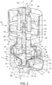
Figure 2 diagrammatically shows in an axonometric sectioned view, in a median plane or a plane passing along the predetermined diaphragm movement direction for opening and closing the inlet duct, the device and actuator inFigure 1 ; -
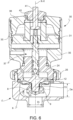
Figure 3 diagrammatically shows, in an axonometric sectioned view with separate parts, the device and actuator inFigure 1 ; -
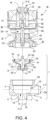
Figure 4 shows in section a median plane or a plane passing along the predetermined diaphragm movement direction for opening and closing the inlet duct, the device and actuator inFigure 1 ; -
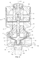
Figure 5 andFigure 6 show in section, in a median plane or a plane passing along the predetermined diaphragm movement direction for opening and closing the inlet duct, the device and actuator inFigure 1 in the closed and respectively open position. - The present invention will now be described in detail with reference to the accompanying drawings to allow those skilled in the art to practice and use it. Various changes to the embodiments described will be readily apparent to those skilled in the art and the general principles described may be applied to other embodiments and applications without departing from the scope of protection of the present invention, as defined in the appended claims. Therefore, the present invention should not be considered as limited to the embodiments described and shown, but should be granted the broadest scope of protection in compliance with the features described and claimed.
- Unless otherwise defined, all the technical and scientific terms used herein have the same meaning commonly used by those of ordinary skill in the field of the present invention. In case of a conflict, the present description, including the definitions provided, will be binding. Furthermore, the examples are merely provided for illustrative purposes, and as such should not be considered as limiting.
- In order to facilitate the understanding of the embodiments described herein, reference will be made to some specific embodiments and a specific language will be used to describe them. The terminology used in this document has the purpose of describing only particular embodiments, and is not intended to limit the scope of the present invention.
- In accordance with the invention, a fluid shut-off
device 1 comprises avalve body 2. - Said
valve body 2 at least partially delimits aninlet duct 3 and anoutlet duct 4. - Said
inlet duct 3 has a predetermined transverse inlet duct dimension Di. - In accordance with an embodiment, said transverse inlet duct dimension Di is the diameter of the
inlet duct 3 with a tubular shape. In accordance with an embodiment, saidoutlet duct 4 has a predetermined transverse outlet duct dimension De. In accordance with an embodiment, said transverse outlet duct dimension De is the diameter of theoutlet duct 4 with a tubular shape. - Said
valve body 2 comprises anintermediate portion 5. Saidintermediate portion 5 at least partially delimits anintermediate chamber 6; saidintermediate chamber 6 provides a fluid connection between saidinlet duct 3 and saidoutlet duct 5. - Said
inlet duct 3 comprises an inletduct connection edge 7 formed by the intersection between saidintermediate portion 5 and saidinlet duct 3. - In accordance with an embodiment, said
outlet duct 4 comprises an outletduct connection edge 4 formed by the intersection between saidintermediate portion 5 and saidoutlet duct 4. - Said
intermediate chamber 6 comprises a sealingsurface 14. - In accordance with an embodiment, said sealing
surface 14 is arranged about said inletduct connection edge 7. - Said
intermediate chamber 6 accommodates adiaphragm 8. -
Said diaphragm 8 has a body in a single piece. -
Said diaphragm 8 comprises a diaphragm sealing portion 9; said diaphragm sealing portion 9, in the closing position of theinlet duct 3, cooperates, by means of adiaphragm support surface 20, with said sealingsurface 14 to occlude saidinlet duct 3. -
Said diaphragm 8 comprises adiaphragm bending portion 10; saiddiaphragm bending portion 10 permanently connects the diaphragm sealing portion 9 to thevalve body 2 so as to exclusively operate under bending. - Said diaphragm sealing portion 9 delimits a
diaphragm seat 11. - Said fluid shut-off
device 1 further comprises acontrol element 12. - Said
control element 12 comprises acontrol stem 13 comprising a predetermined transverse control stem dimension Dp. - Said control stem 13 is integrally received in said
diaphragm seat 11. - Said control stem 13 transmits a movement to said diaphragm sealing portion 9 at least between said closing position of the
inlet duct 3 and an opening position of theinlet duct 3, moving along a predetermined diaphragm movement direction X-X. - According to the invention, said sealing
surface 14 is a flat sealing surface placed orthogonally to said predetermined diaphragm movement direction X-X. For example, but not necessarily, said sealingsurface 14 is an annular flat surface. For example, but not necessarily, said sealingsurface 14 is a surface surrounding said inletduct connection edge 7 or said outlet duct connection edge. - Said
diaphragm support surface 20 is a flat support surface placed orthogonally to said predetermined diaphragm movement direction X-X. For example, but not necessarily, saiddiaphragm support surface 20 is an annular flat surface. - Said transverse control stem dimension Dp is between a value greater than said transverse inlet duct dimension Di and a dimension which leaves a distance Dg, measured on a plane orthogonal to said predetermined diaphragm movement direction X-X, between said control stem 13 and said inlet
duct connection edge 7, lower than 25% of the transverse inlet duct dimension Di. - According to the invention, said control stem 13 comprises a self-tapping
stem thread 27 which screws on by entering into the body of saiddiaphragm 8 thus creating adiaphragm thread 28 in thediaphragm seat 11, thus creating a close coupling between the profile of said self-tappingstem thread 27 and said body of thediaphragm 8. By virtue of the provision of a self-tapping thread, the control stem penetrates deforming the wall of thediaphragm 8 which delimits thediaphragm seat 11, deforming the material of saiddiaphragm 8 which enters between the crests of thethread 44 and creates a firm connection between the control stem and thediaphragm 8, a firm connection which allows many or very numerous opening and closing cycles of thediaphragm 8 without thereby showing the slightest movement between the diaphragm and the stem. - The combination of the features of the transverse control stem dimension Dp and inlet duct dimension Di and the close coupling created by the self-tapping
stem thread 27 in the body of thediaphragm 8 creates a solution capable of reduced or very reduced deformations or dimensional changes of thediaphragm 8 also over time, ensuring, over time, the correct operation of the device, always ensuring a perfect seal over time with an optimal and precise positioning of thediaphragm 8 which faithfully and precisely follows the movement of thecontrol stem 13. - In accordance with the invention, said self-tapping
stem thread 27 is a thread of the cortical type which deforms the body of thediaphragm 8 by screwing into the wall of saiddiaphragm seat 11, so as to penetrate into the body of thediaphragm 8 with a resistant section of the body of thediaphragm 8 which is subjected to the thrust in closing and pulling during the opening of thediaphragm 8. - In accordance with an embodiment, said self-tapping
stem thread 27 comprises tapered and pointed thread crests 44 of the control stem 13 with a predetermined thread height, which leave ahelical thread channel 45 therebetween of a size similar to said thread height, capable of receiving the material of the body of thediaphragm 8 deformed by said thread crests 44 so as to completely fill saidhelical thread channel 45. - In accordance with an embodiment, said self-tapping
stem thread 27 comprises tapered and pointed thread crests 44 of the control stem 13 with a predetermined thread height varying from 1/2 to 1/4 of the thickness of the body of thediaphragm 8 in the narrower section thereof which forms saiddiaphragm seat 11, so as to penetrate for a depth varying between 1/2 and 1/4 into the body of thediaphragm 8 creating a resistant section of the body of thediaphragm 8 which interacts with said thread crests 44 and resists repeated cycles when subjected to thrust during the closing and to pulling during the opening of thediaphragm 8. - In accordance with an embodiment, said self-tapping
stem thread 27 comprises tapered and pointed thread crests 44 of the control stem 13 with a predetermined thread height equal to 1/3 of the thickness of the body of thediaphragm 8 in the narrower section thereof which forms saiddiaphragm seat 11, so as to penetrate for a depth equal to 1/3 into the body of thediaphragm 8 creating a resistant section of the body of thediaphragm 8 which interacts with said thread crests 44 and resists repeated cycles when subjected to thrust during the closing and to pulling during the opening of thediaphragm 8. - In accordance with an embodiment, said control stem 13 comprises a
stem head 46 placed at the end of saidcontrol stem 13. - In accordance with an embodiment, said
stem head 46 comprises a flatstem end surface 47 orthogonal to said predetermined diaphragm movement direction X-X which abuts against theseat bottom 48 of saiddiaphragm seat 11, integrating said control stem 13 with saiddiaphragm 8. - In accordance with an embodiment, said
stem head 46 is separated from said self-tappingstem thread 27 by means of adischarge groove 49 which, when said control stem 13 is inserted with the self-tappingstem thread 27 thereof into the wall which delimits saiddiaphragm seat 11, deforming the material of saiddiaphragm 8, said deformed material enters saiddischarge groove 49 preventing the unscrewing of said control stem from the coupling position thereof to saiddiaphragm 8. By virtue of the provision of thisdischarge groove 49 it is ensured that the material of the body of thediaphragm 8, when deformed by the forced screwing of the cortical thread, deforms and enters saiddischarge groove 49, creating an undercut stop which locks the control stem 13 in the perfect operating position thereof, which ensures very numerous operating opening and closing cycles, avoiding losing the relative position between thecontrol stem 13 and thediaphragm 8 and between thediaphragm 8 and the intermediatechamber sealing surface 14, creating a perfect seal of the device over time. - In accordance with an embodiment, said transverse control stem dimension Dp leaves a distance, measured on a plane orthogonal to said predetermined diaphragm movement direction X-X, between said control stem 13 and said inlet
duct connection edge 7, lower than 22% of the transverse inlet duct dimension Di. - In accordance with an embodiment, said fluid shut-off
device 1 is a Clean & Aseptic Design or CAD device, i.e., adevice 1 for applications in which contamination between successive fluids processed by the device is not allowed and a complete cleaning of theintermediate chamber 6 must be possible without necessarily disassembling the device itself. - As it may be seen from the embodiments shown in the Figures and in accordance with an embodiment, said
device 1 comprises avalve body 2, a slidingbody 24 fitted into one end of saidvalve body 2 and fastened thereon with a threadedtightening ring nut 25. - Connected to said sliding
body 24, apneumatic actuator cylinder 35 is provided, closed at the top by apneumatic actuator top 36 with which it forms apressure chamber 37. - A pressurized fluid supply duct for the movement of the
piston 38 is present in saidpneumatic actuator cylinder 35 to supply pressurized fluid to saidpressure chamber 37. - Accommodated in said
pressure chamber 37, apneumatic actuator piston 39 is provided, to which acontrol shaft 29 is connected. - In accordance with an embodiment, said
device 1 further comprises anopen valve indicator 40. - Said
open valve indicator 40 comprises anindicator stem 41 resting on saidcontrol shaft 29 or saidpneumatic actuator piston 39 and received free to come out of saidpneumatic actuator top 36 through acap 42. - An elastic element or
spring 31 constantly biases saidpneumatic actuator piston 39 in the valve closing position, i.e., in the closing position of saiddiaphragm 8. -
Seals 43 are provided in the moving members to allow a fluid seal of saidpressure chamber 37. - Said
control element 12 is connected, for example, idle in rotation but constrained in translation, to saidcontrol shaft 29. - As mentioned above, the sliding
body 24 is fitted into one end of saidvalve body 2 with aconnection flange 23 thereof and accommodates saidcontrol element 12 with the control stem 13 thereof fastened to saiddiaphragm 8. - In the examples shown in the Figures, the
diaphragm 8 is axisymmetric in shape and is in a single piece. - The
diaphragm 8 comprises adiaphragm connecting portion 21 having an annulardiaphragm attachment body 22 constrained, pack-tightened, between saidconnection flange 23 and saidvalve body 2. - The
diaphragm 8 further comprises adiaphragm bending portion 10 and a diaphragm sealing portion 9. - The
diaphragm bending portion 10 connects said diaphragm sealing portion 9 to saiddiaphragm connecting portion 21 and deforms under bending to allow said diaphragm sealing portion 9 to pass from a closing position of the outlet gap of saidinlet duct 3 in saidintermediate chamber 6 to an opening position of said outlet gap. - In accordance with an embodiment, the
diaphragm bending portion 10 has a flat or slightly concave or conical shape, preventing it from folding back on itself when the diaphragm is in the closed position. - In accordance with an embodiment, the
valve body 2 comprises an annular and flat intermediatechamber sealing surface 14 adapted to receive, as support and sealing, said diaphragm sealing portion 9 occluding the outlet gap of theinlet duct 3. - In accordance with an embodiment, in said closing position of the
inlet duct 3 of the sealing diaphragm 9 the distance, measured parallel to said predetermined diaphragm movement direction X-X, between said control stem 13 and said inletduct connection edge 7, is between 7% and 15% of the transverse inlet duct dimension Di. - In accordance with an embodiment, at least one
diaphragm portion 8 surrounds one end of saidcontrol stem 13. - In accordance with an embodiment, said
diaphragm 8 separates saidcontrol element 12 from theintermediate chamber 6. - In accordance with an embodiment, said
intermediate chamber 6 is delimited by saidintermediate portion 5 of saidvalve body 2 and by saiddiaphragm 8, as well as by gaps oropenings inlet duct 3 and theoutlet duct 4. - In accordance with an embodiment, said
diaphragm 8 separates saidintermediate chamber 6 from a controlelement sliding chamber 17; said controlelement sliding chamber 17 receives and guides saidcontrol element 12 in the movement thereof between said closing position of theinlet duct 3 to an opening position of theinlet duct 3. - In accordance with an embodiment, said
diaphragm 8 is axisymmetric in shape. - In accordance with an embodiment, said diaphragm sealing portion 9 is cup-shaped.
- In accordance with an embodiment, said diaphragm sealing portion 9 comprises a
diaphragm stem 18 and anenlarged diaphragm base 19. - In accordance with an embodiment, said
enlarged diaphragm base 19 comprises adiaphragm support surface 20 which sealingly cooperates with said sealingsurface 14 of theintermediate chamber 6. - In accordance with an embodiment, said
diaphragm bending portion 10 is inverted dome-shaped. - In accordance with an embodiment, said
diaphragm bending portion 10 connects to said valve body by means of adiaphragm connecting portion 21. - In accordance with an embodiment, said
diaphragm connecting portion 21 comprises an annulardiaphragm attachment body 22 adapted to pack-tighten thediaphragm 8 between saidvalve body 2 and aconnection flange 23 of a slidingbody 24. - In accordance with an embodiment, said sliding
body 24 delimits a controlelement sliding chamber 17 adapted to receive and guide saidcontrol element 12. - In accordance with an embodiment, said sliding
body 24 is connected to saidvalve body 2 by means of a threadedring nut 25 screwed onto an externally threadedportion 26 of saidvalve body 2. - In accordance with an embodiment, said
diaphragm 8 is made of polytetrafluoroethylene, called PTFE. - According to an embodiment, said
valve body 2 is made of stainless steel or of another alloy having good corrosion resistance. - In accordance with an embodiment, said
control element 12 is made of stainless steel. - In accordance with the invention, said control stem 13 comprises a self-tapping
stem thread 27 which screws on by entering into the body of saiddiaphragm 8 thus creating adiaphragm thread 28 in thediaphragm seat 11, thus creating a close coupling between the profile of said self-tappingstem thread 27 and said body of thediaphragm 8. - In accordance with an embodiment, the coupling between said control stem 13 and the body of said
diaphragm 8 is so close that an attempt to unscrew the parts would involve breaking thediaphragm 8. - In accordance with an embodiment, said
control element 12 is made of stainless steel and the control stem 13 thereof has a thread of a cortical type which deforms the body made of PTFE of thediaphragm 8 by screwing. The crests of the thread of the control stem 13 are very tapered and pointed, and the channel of the helicoid of the thread is very wide. The height of the thread is very prominent, to increase the resistant section in the body made of PTFE of thediaphragm 8 which will be subjected to thrust during the closing and to traction during the opening. - In accordance with an embodiment, said
control element 12 is connected to acontrol shaft 29 of anactuator 30. - In accordance with an embodiment, said
control element 12 is connected to acontrol shaft 29 of apneumatic actuator 30. - In accordance with an embodiment, said
control element 12 is constantly biased to said closing position of theinlet duct 3 by aspring 31. - In accordance with an embodiment, said
control element 12 is an element in a single piece. - In accordance with an embodiment, said
control element 12 is received in saiddiaphragm seat 11. - In accordance with an embodiment, said
control element 12 comprises acontrol element plate 32. - In accordance with an embodiment, said
control element plate 32 is in a single piece with saidcontrol stem 13. - In accordance with an embodiment, said
control element 12 comprises acontrol element plate 32. - In accordance with an embodiment, the
control element plate 32 comprises adiaphragm support surface 33 facing saiddiaphragm bending portion 10. - In accordance with an embodiment, said
control element 12 comprises acontrol element plate 32. - In accordance with an embodiment, said
control element plate 32 comprises adiaphragm support surface 33 and saiddiaphragm support surface 33 is conical or in the shape of a spherical sector. - In accordance with an embodiment, said
control element 12 comprises acontrol element plate 32. - In accordance with an embodiment, said
control element plate 32 comprises adiaphragm support surface 33. - In accordance with an embodiment, in said position of the
diaphragm 8 for closing theinlet duct 3 and in a condition in which thediaphragm 8 is not worn or aged, adiaphragm clearance 34 exists between saiddiaphragm support surface 33 and saiddiaphragm bending portion 10; and in which saiddiaphragm clearance 34 increases by moving from said diaphragm sealing portion 9 to adiaphragm connecting portion 21 for the connection of saiddiaphragm 8 to thevalve body 2. - Those skilled in the art may make many changes and adaptations to the embodiments described above or may replace elements with others, which are functionally equivalent, in order to meet contingent needs without however departing from the scope of the appended claims.
-
- 1
- fluid shut-off device
- 2
- valve body
- 3
- inlet duct
- 4
- outlet duct
- 5
- intermediate portion
- 6
- intermediate chamber
- 7
- inlet duct connection edge
- 8
- diaphragm
- 9
- diaphragm sealing portion
- 10
- diaphragm bending portion
- 11
- diaphragm seat
- 12
- control element
- 13
- control stem
- 14
- intermediate chamber sealing surface
- 15
- gap or opening for accessing the inlet duct
- 16
- gap or opening for accessing the outlet duct
- 17
- control element sliding chamber
- 18
- diaphragm stem
- 19
- enlarged diaphragm base
- 20
- diaphragm support surface
- 21
- diaphragm connecting portion
- 22
- annular diaphragm attachment body
- 23
- connection flange
- 24
- sliding body
- 25
- threaded ring nut
- 26
- valve body threaded portion
- 27
- self-tapping stem thread
- 28
- diaphragm thread
- 29
- control shaft
- 30
- actuator
- 31
- spring
- 32
- control element plate
- 33
- diaphragm support surface
- 34
- diaphragm clearance
- 35
- pneumatic actuator cylinder
- 36
- pneumatic actuator top
- 37
- pressure chamber
- 38
- pressurized fluid supply duct
- 39
- pneumatic actuator piston
- 40
- open valve indicator
- 41
- indicator stem
- 42
- cap
- 43
- seals
- 44
- thread crests
- 45
- helical thread channel
- 46
- stem head
- 47
- stem end surface
- 48
- seat bottom
- 49
- discharge groove
- Di
- transverse inlet duct dimension
- De
- transverse outlet duct dimension
- Dp
- transverse control stem dimension
- Dg
- distance between control stem and sealing surface transverse to X-X
- Dz
- distance, measured parallel to said predetermined diaphragm movement direction X-X, between said control stem and said inlet duct connection edge
- X-X
- predetermined diaphragm movement direction for opening and closing the inlet duct
Claims (10)
- A fluid shut-off device (1) comprising:a valve body (2);said valve body (2) at least partially delimits an inlet duct (3) and an outlet duct (4);said inlet duct (3) having a predetermined transverse inlet duct dimension (Di);said valve body (2) comprises an intermediate portion (5); said intermediate portion (5) at least partially delimits an intermediate chamber (6); said intermediate chamber (6) provides a fluid connection between said inlet duct (3) and said outlet duct (5);whereinsaid inlet duct (3) comprises an inlet duct connection edge (7) formed by the intersection between said intermediate portion (5) and said inlet duct (3);said intermediate chamber (6) comprises a sealing surface (14);said intermediate chamber (6) accommodates a diaphragm (8);said diaphragm (8) has a body in a single piece;said diaphragm (8) comprises a diaphragm sealing portion (9); said diaphragm sealing portion (9),in closing position of the inlet duct (3), cooperates, by means of a diaphragm support surface (20),with said sealing surface (14) to occlude said inlet duct (3);said diaphragm (8) comprises a diaphragm bending portion (10); said diaphragm bending portion (10) permanently connects the diaphragm sealing portion (9) to the valve body (2) so as to operate exclusively under bending;said diaphragm sealing portion (9) delimits a diaphragm seat (11);said fluid shut-off device (1) further comprises a control element (12);said control element (12) comprises a control stem (13) comprising a predetermined transverse control stem dimension (Dp);said control stem (13) is integrally received in said diaphragm seat (11);said control stem (13) transmits a movement to said diaphragm sealing portion (9) at least between said closing position of the inlet duct (3) to an opening position of the inlet duct (3), moving along a predetermined diaphragm movement direction (X-X);whereinsaid sealing surface (14) is a flat sealing surface placed orthogonally to said predetermined diaphragm movement direction (X-X); and whereinsaid diaphragm support surface (20) is a flat support surface placed orthogonally to said predetermined diaphragm movement direction (X-X); and whereinsaid transverse control stem dimension (Dp) is between a value greater than said transverse inlet duct dimension (Di) and a dimension which leaves a distance (Dg), measured on a plane orthogonalto said predetermined diaphragm movement direction (X-X), between said control stem (13) and said inlet duct connection edge (7), lower than 25% of the transverse inlet duct dimension (Di);characterized in thatsaid control stem (13) comprises a self-tapping stem thread (27) which screws on by entering into the body of said diaphragm (8) thus creating a diaphragm thread (28) in the diaphragm seat (11), thus creating a close coupling between the profile of said self-tapping stem thread (27) and said body of the diaphragm (8), and whereinsaid self-tapping stem thread (27) is a thread of a cortical type which deforms the body of the diaphragm (8) by screwing into the wall of said diaphragm seat (11), so as to penetrate into the body of the diaphragm (8) with a resistant section of the body of the diaphragm (8) which is subjected to thrust during the closing and to pulling during the opening of the diaphragm (8).
- A fluid shut-off device (1) according to claim 1, whereinsaid self-tapping stem thread (27) comprises tapered and pointed thread crests (44) of the control stem (13) with a predetermined thread height, which leave a helical thread channel (45) therebetween of a size similar to said thread height, capable of receiving the material of the body of the diaphragm (8) deformed by said thread crests (44) so as to completely fill said helical thread channel (45); and/or whereinsaid self-tapping stem thread (27) comprises tapered and pointed thread crests (44) of the control stem (13) with a predetermined thread height varying from 1/2 to 1/4 of the thickness of the body of the diaphragm (8) in the narrower section thereof which forms said diaphragm seat (11), so as to penetrate for a depth varying between 1/2 and 1/4 into the body of the diaphragm (8) creating a resistant section of the body of the diaphragm (8) which interacts with said thread crests (44) and resists repeated cycles when subjected to thrust during the closing and to pulling during the opening of the diaphragm (8); or whereinsaid self-tapping stem thread (27) comprises tapered and pointed thread crests (44) of the control stem (13) with a predetermined thread height equal to 1/3 of the thickness of the body of the diaphragm (8) in the narrower section thereof which forms said diaphragm seat (11), so as to penetrate for a depth equal to 1/3 into the body of the diaphragm (8) creating a resistant section of the body of the diaphragm (8) which interacts with said thread crests (44) and resists repeated cycles when subjected to the thrust in closing and pulling during the opening of the diaphragm (8);said transverse control stem dimension (Dp) leaves a distance (Dg), measured on a plane orthogonal to said predetermined diaphragm movement direction (X-X), between said control stem (13) and said inlet duct connection edge (7), lower than 22% of the transverse inlet duct dimension (Di).
- A fluid shut-off device (1) according to claim 1 or 2, wherein
in said closing position of the inlet duct (3) of the sealing diaphragm (9) the distance (Dz), measured parallel to said predetermined diaphragm movement direction (X-X), between said control stem (13) and said inlet duct connection edge (7), is between 7% and 15% of the transverse inlet duct dimension (Di). - A fluid shut-off device (1) according to any one of the preceding claims, whereinat least one diaphragm portion (8) surrounds one end of said control stem (13);and/or whereinsaid diaphragm (8) separates said control element (12) from the intermediate chamber (6).
- A fluid shut-off device (1) according to any one of the preceding claims, whereinsaid intermediate chamber (6) is delimited by said intermediate portion (5) of said valve body (2) and by said diaphragm (8), as well as by gaps or openings (15, 16) for accessing the inlet duct (3) and the outlet duct (4);and/or whereinsaid diaphragm (8) separates said intermediate chamber (6) from a control element sliding chamber (17); said control element sliding chamber (17) receives and guides said control element (12) in the movement thereof between said closing position of the inlet duct (3) to an opening position of the inlet duct (3).
- A fluid shut-off device (1) according to any one of the preceding claims, whereinsaid diaphragm (8) is axisymmetric in shape;and/or whereinsaid diaphragm sealing portion (9) is cup-shaped;and/or whereinsaid diaphragm sealing portion (9) comprises a diaphragm stem (18) and an enlarged diaphragm base (19); and whereinsaid enlarged diaphragm base (19) comprises a diaphragm support surface (20) which sealingly cooperates with said sealing surface (14) of the intermediate chamber (6);and/or whereinsaid diaphragm bending portion (10) is inverted dome-shaped;and/or whereinsaid diaphragm bending portion (10) connects to said valve body by means of a diaphragm connecting portion (21).
- A fluid shut-off device (1) according to any one of the preceding claims, whereinsaid diaphragm (8) is made of polytetrafluoroethylene, referred to as PTFE, obtained by means of the mechanical machining of billets or bars produced under compression;and/or whereinsaid valve body (2) is made of stainless steel;and/or whereinsaid control element (12) is made of stainless steel.
- A fluid shut-off device (1) according to any one of the preceding claims, whereinsaid control stem (13) comprises a stem head (46) placed at the end of said control stem (13); and whereinsaid stem head (46) comprises a flat stem end surface (47) orthogonal to said predetermined diaphragm movement direction (X-X) which abuts against the seat bottom (48) of said diaphragm seat (11), integrating said control stem (13) with said diaphragm (8); and/or whereinsaid stem head (46) is separated from said self-tapping stem thread (27) by means of a discharge groove (49) which, when said control stem (13) is inserted with the self-tapping stem thread (27) thereof into the wall which delimits said diaphragm seat (11), deforming the material of said diaphragm (8), said deformed material enters said discharge groove (49) preventing the unscrewing of said control stem from the coupling position thereof to said diaphragm (8).
- A fluid shut-off device (1) according to any one of the preceding claims, whereinsaid control element (12) is connected to a control shaft (29) of an actuator (30);and/or whereinsaid control element (12) is connected to a control shaft (29) of a pneumatic actuator (30);and/or whereinsaid control element (12) is constantly biased to said closing position of the inlet duct (3) by a spring (31).
- A fluid shut-off device (1) according to any one of the preceding claims, whereinsaid control element (12) is an element in a single piece;and/or whereinsaid control element (12) comprises a control element plate (32); and whereinsaid control element plate (32) is in a single piece with said control stem (13);and/or whereinsaid control element (12) comprises a control element plate (32); and whereinthe control element plate (32) comprises a diaphragm support surface (33) facing said diaphragm bending portion (10);and/or whereinsaid control element (12) comprises a control element plate (32); and whereinsaid control element plate (32) comprises a diaphragm support surface (33) and said diaphragm support surface (33) is conical or in the shape of a spherical sector;and/or whereinsaid control element (12) comprises a control element plate (32); and whereinsaid control element plate (32) comprises a diaphragm support surface (33); and whereinin said position of the diaphragm (8) for closing the inlet duct (3) and in a condition in which the diaphragm (8) is not worn or aged, a diaphragm clearance (34) exists between said diaphragm support surface (33) and said diaphragm bending portion (10); and wherein said diaphragm clearance (34) increases by moving from said diaphragm sealing portion (9) to a diaphragm connecting portion (21) for the connection of said diaphragm (8) to the valve body (2).
Applications Claiming Priority (2)
| Application Number | Priority Date | Filing Date | Title |
|---|---|---|---|
| IT102020000014203A IT202000014203A1 (en) | 2020-06-15 | 2020-06-15 | FLUID SHUT-OFF DEVICE |
| PCT/IB2021/055256 WO2021255634A1 (en) | 2020-06-15 | 2021-06-15 | Fluid shut-off device |
Publications (2)
| Publication Number | Publication Date |
|---|---|
| EP4165331A1 EP4165331A1 (en) | 2023-04-19 |
| EP4165331B1 true EP4165331B1 (en) | 2024-04-03 |
Family
ID=72473657
Family Applications (1)
| Application Number | Title | Priority Date | Filing Date |
|---|---|---|---|
| EP21737774.6A Active EP4165331B1 (en) | 2020-06-15 | 2021-06-15 | Fluid shut-off device |
Country Status (9)
| Country | Link |
|---|---|
| US (1) | US20230228343A1 (en) |
| EP (1) | EP4165331B1 (en) |
| JP (1) | JP7436086B2 (en) |
| KR (1) | KR20230023038A (en) |
| CN (1) | CN115769014A (en) |
| CA (1) | CA3185031A1 (en) |
| IT (1) | IT202000014203A1 (en) |
| MX (1) | MX2022016013A (en) |
| WO (1) | WO2021255634A1 (en) |
Families Citing this family (1)
| Publication number | Priority date | Publication date | Assignee | Title |
|---|---|---|---|---|
| CN217150508U (en) * | 2021-12-22 | 2022-08-09 | 科勒(中国)投资有限公司 | Pneumatic valve control device |
Citations (2)
| Publication number | Priority date | Publication date | Assignee | Title |
|---|---|---|---|---|
| EP0072681B1 (en) * | 1981-08-13 | 1986-07-30 | American Standard Inc. (a Delaware corporation) | Diaphragm valve assembly for controlling fluid flow |
| CN213839569U (en) * | 2020-12-07 | 2021-07-30 | 余姚市永创电磁阀有限公司 | Isolated anticorrosive solenoid valve |
Family Cites Families (19)
| Publication number | Priority date | Publication date | Assignee | Title |
|---|---|---|---|---|
| FR1249282A (en) | 1959-11-07 | 1960-12-30 | Advanced diaphragm valve | |
| US3134570A (en) | 1960-05-16 | 1964-05-26 | Saunders Valve Co Ltd | Diaphragm valve |
| GB1509552A (en) | 1975-03-06 | 1978-05-04 | Saunders Valve Co Ltd | Fluid flow control valves |
| IL55233A0 (en) * | 1977-08-16 | 1978-09-29 | Niemand C W P | Improvements to fluid valves |
| US4359204A (en) | 1980-11-06 | 1982-11-16 | General Motors Corporation | Rod operated valve |
| SE445852B (en) | 1984-09-14 | 1986-07-21 | Steridose Systems Ab | Valve device |
| JP2676352B2 (en) * | 1988-01-21 | 1997-11-12 | 東亜医用電子株式会社 | Fluid control valve and manufacturing method thereof |
| US5152500A (en) | 1991-03-27 | 1992-10-06 | Asepco, Inc. | Aseptic valve construction |
| DE4302556A1 (en) | 1993-01-29 | 1994-08-04 | Mueller Apparatebau Gmbh & Co | Diaphragm valve with closing stroke limitation |
| US5609185A (en) | 1995-05-31 | 1997-03-11 | H-Tech, Inc. | Valve indicator and handle assembly |
| US6575431B2 (en) | 1999-09-14 | 2003-06-10 | Spears Manufacturing Co. | Weir-type diaphragm valve with raised arcuate bead |
| JP3392813B2 (en) * | 2000-07-07 | 2003-03-31 | エスエムシー株式会社 | Two-way valve |
| JP3704657B2 (en) | 2000-10-11 | 2005-10-12 | マイクロゼロ株式会社 | Diaphragm valve |
| JP4221206B2 (en) | 2002-11-06 | 2009-02-12 | シーケーディ株式会社 | Diaphragm |
| US7063304B2 (en) * | 2003-07-11 | 2006-06-20 | Entegris, Inc. | Extended stroke valve and diaphragm |
| US20060065868A1 (en) * | 2004-09-28 | 2006-03-30 | Strong Warren N | Diaphragm valve |
| JP5138863B2 (en) * | 2004-12-10 | 2013-02-06 | Ckd株式会社 | Diaphragm valve |
| JP4355738B2 (en) * | 2007-07-20 | 2009-11-04 | シーケーディ株式会社 | Fluid control valve |
| DE102011080139A1 (en) | 2011-07-29 | 2013-01-31 | GEMÜ Gebr. Müller Apparatebau GmbH & Co. KG | diaphragm valve |
-
2020
- 2020-06-15 IT IT102020000014203A patent/IT202000014203A1/en unknown
-
2021
- 2021-06-15 US US18/009,971 patent/US20230228343A1/en active Pending
- 2021-06-15 CA CA3185031A patent/CA3185031A1/en active Pending
- 2021-06-15 JP JP2023520558A patent/JP7436086B2/en active Active
- 2021-06-15 KR KR1020237001787A patent/KR20230023038A/en unknown
- 2021-06-15 WO PCT/IB2021/055256 patent/WO2021255634A1/en unknown
- 2021-06-15 CN CN202180042713.2A patent/CN115769014A/en active Pending
- 2021-06-15 MX MX2022016013A patent/MX2022016013A/en unknown
- 2021-06-15 EP EP21737774.6A patent/EP4165331B1/en active Active
Patent Citations (2)
| Publication number | Priority date | Publication date | Assignee | Title |
|---|---|---|---|---|
| EP0072681B1 (en) * | 1981-08-13 | 1986-07-30 | American Standard Inc. (a Delaware corporation) | Diaphragm valve assembly for controlling fluid flow |
| CN213839569U (en) * | 2020-12-07 | 2021-07-30 | 余姚市永创电磁阀有限公司 | Isolated anticorrosive solenoid valve |
Also Published As
| Publication number | Publication date |
|---|---|
| KR20230023038A (en) | 2023-02-16 |
| US20230228343A1 (en) | 2023-07-20 |
| WO2021255634A1 (en) | 2021-12-23 |
| JP7436086B2 (en) | 2024-02-21 |
| CN115769014A (en) | 2023-03-07 |
| MX2022016013A (en) | 2023-02-02 |
| JP2023531564A (en) | 2023-07-24 |
| IT202000014203A1 (en) | 2021-12-15 |
| EP4165331A1 (en) | 2023-04-19 |
| CA3185031A1 (en) | 2021-12-23 |
Similar Documents
| Publication | Publication Date | Title |
|---|---|---|
| US6672561B2 (en) | Piston diaphragm with integral seal | |
| DE69814815T2 (en) | REED VALVE | |
| US8162286B2 (en) | Piezoelectric driven control valve | |
| US6341758B1 (en) | Gas control module switch mechanism | |
| EP0322406A2 (en) | Bellows valve | |
| EP4165331B1 (en) | Fluid shut-off device | |
| US20070056636A1 (en) | Spring actuated check valve | |
| US20150247582A1 (en) | Apparatus to interface with a corrugated diaphragm | |
| EP1731808A1 (en) | Fluid controller | |
| AU2020200555A1 (en) | Proportional Flow Control Valve Poppet With Flow Control Needle | |
| US5482077A (en) | High pressure abrasive slurry check valve | |
| EP1527296B1 (en) | Sanitary diaphragm valve | |
| CA1291741C (en) | Valve with compressible valve stem and valve body seals | |
| RU2470208C2 (en) | Fluid medium flow rate control device | |
| US4807849A (en) | Fluid flow control device and compression member therefor | |
| US20060011883A1 (en) | Threaded polymer valve seat and valve employing same | |
| US20050035317A1 (en) | Free flow valve and element | |
| US2933284A (en) | Diaphragm packless valve | |
| US20040108000A1 (en) | Ultrahigh-pressure check valve | |
| US4151979A (en) | Diaphragm valve having a Belleville-spring assembly | |
| JP5940859B2 (en) | Decompressor | |
| US4659060A (en) | Stem tip seal | |
| US5083746A (en) | Diaphragm valve with mechanically linked diaphragm | |
| US5167397A (en) | Diaphragm valve with mechanically linked diaphragm | |
| WO2016190875A1 (en) | Apparatus to interface with a corrugated diaphragm |
Legal Events
| Date | Code | Title | Description |
|---|---|---|---|
| STAA | Information on the status of an ep patent application or granted ep patent |
Free format text: STATUS: UNKNOWN |
|
| STAA | Information on the status of an ep patent application or granted ep patent |
Free format text: STATUS: THE INTERNATIONAL PUBLICATION HAS BEEN MADE |
|
| PUAI | Public reference made under article 153(3) epc to a published international application that has entered the european phase |
Free format text: ORIGINAL CODE: 0009012 |
|
| STAA | Information on the status of an ep patent application or granted ep patent |
Free format text: STATUS: REQUEST FOR EXAMINATION WAS MADE |
|
| 17P | Request for examination filed |
Effective date: 20221201 |
|
| AK | Designated contracting states |
Kind code of ref document: A1 Designated state(s): AL AT BE BG CH CY CZ DE DK EE ES FI FR GB GR HR HU IE IS IT LI LT LU LV MC MK MT NL NO PL PT RO RS SE SI SK SM TR |
|
| DAV | Request for validation of the european patent (deleted) | ||
| DAX | Request for extension of the european patent (deleted) | ||
| GRAP | Despatch of communication of intention to grant a patent |
Free format text: ORIGINAL CODE: EPIDOSNIGR1 |
|
| STAA | Information on the status of an ep patent application or granted ep patent |
Free format text: STATUS: GRANT OF PATENT IS INTENDED |
|
| INTG | Intention to grant announced |
Effective date: 20231027 |
|
| GRAS | Grant fee paid |
Free format text: ORIGINAL CODE: EPIDOSNIGR3 |
|
| GRAA | (expected) grant |
Free format text: ORIGINAL CODE: 0009210 |
|
| STAA | Information on the status of an ep patent application or granted ep patent |
Free format text: STATUS: THE PATENT HAS BEEN GRANTED |
|
| AK | Designated contracting states |
Kind code of ref document: B1 Designated state(s): AL AT BE BG CH CY CZ DE DK EE ES FI FR GB GR HR HU IE IS IT LI LT LU LV MC MK MT NL NO PL PT RO RS SE SI SK SM TR |
|
| REG | Reference to a national code |
Ref country code: CH Ref legal event code: EP |
|
| REG | Reference to a national code |
Ref country code: DE Ref legal event code: R096 Ref document number: 602021011380 Country of ref document: DE |