EP4244136B1 - Verfahren zur bestimmung mindestens einer leistungsgrenze eines hybridantriebsstrangs für ein transportfahrzeug, insbesondere ein flugzeug - Google Patents
Verfahren zur bestimmung mindestens einer leistungsgrenze eines hybridantriebsstrangs für ein transportfahrzeug, insbesondere ein flugzeug Download PDFInfo
- Publication number
- EP4244136B1 EP4244136B1 EP21802372.9A EP21802372A EP4244136B1 EP 4244136 B1 EP4244136 B1 EP 4244136B1 EP 21802372 A EP21802372 A EP 21802372A EP 4244136 B1 EP4244136 B1 EP 4244136B1
- Authority
- EP
- European Patent Office
- Prior art keywords
- power
- margin
- margins
- reference point
- drive train
- Prior art date
- Legal status (The legal status is an assumption and is not a legal conclusion. Google has not performed a legal analysis and makes no representation as to the accuracy of the status listed.)
- Active
Links
Images



Classifications
-
- B—PERFORMING OPERATIONS; TRANSPORTING
- B64—AIRCRAFT; AVIATION; COSMONAUTICS
- B64D—EQUIPMENT FOR FITTING IN OR TO AIRCRAFT; FLIGHT SUITS; PARACHUTES; ARRANGEMENT OR MOUNTING OF POWER PLANTS OR PROPULSION TRANSMISSIONS IN AIRCRAFT
- B64D43/00—Arrangements or adaptations of instruments
-
- B—PERFORMING OPERATIONS; TRANSPORTING
- B64—AIRCRAFT; AVIATION; COSMONAUTICS
- B64D—EQUIPMENT FOR FITTING IN OR TO AIRCRAFT; FLIGHT SUITS; PARACHUTES; ARRANGEMENT OR MOUNTING OF POWER PLANTS OR PROPULSION TRANSMISSIONS IN AIRCRAFT
- B64D27/00—Arrangement or mounting of power plants in aircraft; Aircraft characterised by the type or position of power plants
- B64D27/02—Aircraft characterised by the type or position of power plants
- B64D27/30—Aircraft characterised by electric power plants
- B64D27/33—Hybrid electric aircraft
-
- B—PERFORMING OPERATIONS; TRANSPORTING
- B64—AIRCRAFT; AVIATION; COSMONAUTICS
- B64D—EQUIPMENT FOR FITTING IN OR TO AIRCRAFT; FLIGHT SUITS; PARACHUTES; ARRANGEMENT OR MOUNTING OF POWER PLANTS OR PROPULSION TRANSMISSIONS IN AIRCRAFT
- B64D27/00—Arrangement or mounting of power plants in aircraft; Aircraft characterised by the type or position of power plants
- B64D27/02—Aircraft characterised by the type or position of power plants
- B64D27/30—Aircraft characterised by electric power plants
- B64D27/35—Arrangements for on-board electric energy production, distribution, recovery or storage
- B64D27/357—Arrangements for on-board electric energy production, distribution, recovery or storage using batteries
-
- B—PERFORMING OPERATIONS; TRANSPORTING
- B64—AIRCRAFT; AVIATION; COSMONAUTICS
- B64D—EQUIPMENT FOR FITTING IN OR TO AIRCRAFT; FLIGHT SUITS; PARACHUTES; ARRANGEMENT OR MOUNTING OF POWER PLANTS OR PROPULSION TRANSMISSIONS IN AIRCRAFT
- B64D31/00—Power plant control systems; Arrangement of power plant control systems in aircraft
- B64D31/16—Power plant control systems; Arrangement of power plant control systems in aircraft for electric power plants
- B64D31/18—Power plant control systems; Arrangement of power plant control systems in aircraft for electric power plants for hybrid-electric power plants
-
- B—PERFORMING OPERATIONS; TRANSPORTING
- B64—AIRCRAFT; AVIATION; COSMONAUTICS
- B64D—EQUIPMENT FOR FITTING IN OR TO AIRCRAFT; FLIGHT SUITS; PARACHUTES; ARRANGEMENT OR MOUNTING OF POWER PLANTS OR PROPULSION TRANSMISSIONS IN AIRCRAFT
- B64D35/00—Transmitting power from power plants to propellers or rotors; Arrangements of transmissions
- B64D35/02—Transmitting power from power plants to propellers or rotors; Arrangements of transmissions specially adapted for specific power plants
- B64D35/021—Transmitting power from power plants to propellers or rotors; Arrangements of transmissions specially adapted for specific power plants for electric power plants
- B64D35/022—Transmitting power from power plants to propellers or rotors; Arrangements of transmissions specially adapted for specific power plants for electric power plants of hybrid-electric type
- B64D35/024—Transmitting power from power plants to propellers or rotors; Arrangements of transmissions specially adapted for specific power plants for electric power plants of hybrid-electric type of series type
-
- B—PERFORMING OPERATIONS; TRANSPORTING
- B64—AIRCRAFT; AVIATION; COSMONAUTICS
- B64D—EQUIPMENT FOR FITTING IN OR TO AIRCRAFT; FLIGHT SUITS; PARACHUTES; ARRANGEMENT OR MOUNTING OF POWER PLANTS OR PROPULSION TRANSMISSIONS IN AIRCRAFT
- B64D27/00—Arrangement or mounting of power plants in aircraft; Aircraft characterised by the type or position of power plants
- B64D27/02—Aircraft characterised by the type or position of power plants
- B64D27/026—Aircraft characterised by the type or position of power plants comprising different types of power plants, e.g. combination of a piston engine and a gas-turbine
-
- Y—GENERAL TAGGING OF NEW TECHNOLOGICAL DEVELOPMENTS; GENERAL TAGGING OF CROSS-SECTIONAL TECHNOLOGIES SPANNING OVER SEVERAL SECTIONS OF THE IPC; TECHNICAL SUBJECTS COVERED BY FORMER USPC CROSS-REFERENCE ART COLLECTIONS [XRACs] AND DIGESTS
- Y02—TECHNOLOGIES OR APPLICATIONS FOR MITIGATION OR ADAPTATION AGAINST CLIMATE CHANGE
- Y02T—CLIMATE CHANGE MITIGATION TECHNOLOGIES RELATED TO TRANSPORTATION
- Y02T50/00—Aeronautics or air transport
- Y02T50/60—Efficient propulsion technologies, e.g. for aircraft
Definitions
- the present invention relates to the field of hybrid propulsion of a transport vehicle, in particular an aircraft.
- a hybrid propulsion chain comprising several different power sources to drive a plurality of propulsion elements, in particular, at least one turbomachine and at least one electric battery.
- Such a hybrid propulsion chain allows an aircraft to transport goods and merchandise optimally by limiting noise pollution and fuel consumption while improving safety.
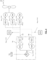
- an aircraft 1 comprising a hybrid propulsion chain 2 which comprises four propulsion elements H1-H4, in particular, propellers.
- Each propulsion element H1-H4 is connected to two electric motors to enable its drive: a primary motor M1A-M4A and a secondary motor M1B-M4B.
- the primary motors M1A-M4A are electrically connected to a primary battery BATA via a primary channel CA while the secondary motors M1B-M4B are electrically connected to a secondary battery BATB via a secondary channel CB.
- the hybrid propulsion chain 2 includes a TG turbogenerator, including a gas turbomachine, to electrically power the M1A-M4A, M1B-M4B electric motors and the BAT, BATB batteries via the CA, CB channels.
- a TG turbogenerator including a gas turbomachine, to electrically power the M1A-M4A, M1B-M4B electric motors and the BAT, BATB batteries via the CA, CB channels.
- the propulsion is called hybrid-series.
- Each hybrid propulsion chain has power limitations which depend on numerous parameters, in particular, its architecture, the maximum torque on the gas turbomachine, the maximum alternating current of the turbogenerator, the maximum current supplied on a channel during electrical generation , the maximum electric current that the battery can deliver, the maximum electric current at which a propulsion motor can operate, etc. In other words, determining a power limit for the hybrid propulsion chain is difficult to determine.
- the propulsion chain can no longer satisfy the demand and can either protect itself by continuing to provide a service but by limiting the power delivered, or follow the power demand until triggering a protection device which potentially leads to a partial or total power cut.
- the pilot may be “surprised” by the refusal (or loss) to deliver the requested power. This can be detrimental if the person is carrying out a “complex” or critical maneuver. Indeed, the latter can hardly compensate for the lack of power, which would have the consequence of affecting flight safety.
- an immediate solution consists of oversizing the power capacity of the propulsion chain in order to have a large safety margin in all conditions of use and all configurations.
- Such a solution cannot be adopted because it impacts the mass of the propulsion chain and therefore reduces the mass that can be loaded by the aircraft.
- One of the objectives of the present invention is to allow the pilot (human or automatic) to permanently determine the available power margin of the hybrid propulsion chain in order to be able to determine the piloting commands that can be carried out while ensuring flight safety. of the aircraft.
- a control system (human or automatic) may be required to engage in over-demanding maneuvers for part of the elements of the propulsion chain. Thanks to the invention, knowing the available margins at any time allows the control system to plan feasible maneuvers while remaining within the available power range.
- the propulsion chain comprises a plurality of power sources of different natures, for example, at least one thermal source (a thermal turbomachine or other) and at least one electrical source (an electric battery, a hydrogen fuel cell). Or other).
- at least one thermal source a thermal turbomachine or other
- at least one electrical source an electric battery, a hydrogen fuel cell. Or other.
- the power consumers are configured to consume power and are for example motors, in particular, electric motors.
- the power consumers are configured to power the propulsion elements, in particular, to cause them to rotate.
- the power consumers are for example electric motors driving the propulsion elements.
- the calculation of instantaneous power margins is particularly complex for a hybrid propulsion chain having numerous and heterogeneous physical quantities (torques and mechanical speed, alternating currents, direct current and voltage, etc.) and varied technologies whose limitations depend on independent factors (atmospheric pressure and temperature for thermal engines, charge level and temperature for batteries, voltage level for electrical equipment). Thanks to the steps according to the invention, the different power parameters are processed methodically in order to evaluate them at the same reference point in order to obtain a relevant minimum power margin.
- the source power margin is obtained by a weighted sum of the normalized power margins of the sources at said reference point.
- weighting factors make it possible to take into account the overall architecture (distribution of power sources and distribution thereof to consumers).
- the consumer power margin is obtained by a weighted sum of the normalized power margins of the consumers at said reference point.
- weighting factors make it possible to take into account the overall architecture (distribution of power sources and distribution of this on consumers).
- the reference point(s) correspond to one or more propulsion elements.
- This is particularly relevant for a piloting system which wishes to know the power available at the level of the propulsion elements (the power useful for moving the aircraft). It is therefore necessary to take into account the energy yields of the different transmission elements. These efficiencies can also vary depending on the conditions of use of the system (eg: depending on the power level, temperature of the electrical equipment, etc.).
- the total power received at a node is distributed in a weighted manner between the power consumers, preferably, according to the nominal power of each consumer. Such a distribution is relevant when consumers have very different nominal powers.
- the individual power margins are grouped along the main axes of the aircraft so as to indicate margins in roll, pitch, yaw.
- the propulsion chain comprises at least one turbogenerator and at least one electric battery as power sources.
- the propulsion chain comprises a plurality of electric motors as power consumers.
- piloting orders are dynamically validated before being implemented, which avoids excessive stress on the propulsion chain.
- the transformation database and the yield database are accessible by the calculator, preferably recorded in said calculator.
- the invention also relates to a transport vehicle, in particular an aircraft, comprising at least one hybrid propulsion chain as presented previously.
- the invention relates to a method for determining a power limit of a hybrid propulsion chain for a transport vehicle, in particular an aircraft.
- the hybrid propulsion chain 2 hereinafter “propulsion chain 2”
- the invention applies to a propulsion chain 2 which is distributed, that is to say, which comprises a plurality of power consumers (distributed system).
- a hybrid propulsion chain can have various architectures.
- a hybrid propulsion chain 2 was presented, of the hybrid-series type, comprising four propulsion elements H1-H4, in particular, propellers.
- Each propulsion element H1-H4 is associated with at least one power source and at least one power consumer.
- each propulsion element H1-H4 is connected to two electric motors to enable its drive: a primary motor M1A-M4A and a secondary motor M1B-M4B.
- the M1A-M4A primary motors are electrically connected to a BATA primary battery via a CA primary channel while the M1B-M4B secondary motors are electrically connected to a BATB secondary battery via a CB secondary channel.
- Propulsion chain 2 includes a TG turbogenerator to electrically power the M1A-M4A, M1B-M4B electric motors and the BAT, BATB batteries via the CA, CB channels.
- a turbogenerator was presented TG as well as electric batteries but the invention applies to any power source, in particular, a fuel cell or an electrical energy store (super capacity, electrochemical battery, etc.).
- the TG turbogenerator includes a TAG gas turbine driving two electrical generators GENA, GENB (a primary generator GENA and a secondary generator GENB).
- the TAG turbomachine comprises a low pressure shaft and a high pressure shaft known to those skilled in the art.
- the TG turbogenerator produces continuous electrical power from the combustion of fuel.
- Each GENA, GENB electric generator transforms this mechanical power into alternating electrical voltage and current Iac TGA , Iac TGB .
- the turbogenerator TG also includes two rectifiers REDA, REDB in order to supply the primary channel CA and the secondary channel CB with voltages and direct electric currents Idc TGA , Idc TGB .
- the CA, CB channels are also powered by the two batteries BATA, BATB which each provide a direct current Idc BATA , Idc BATB .
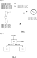
- each BATA, BATB battery is equipped with a control and monitoring system (BMS) which determines the maximum current Idcmax BATA , Idcmax BATB ([ Fig.2 ]) that she can deliver at any moment. This maximum current therefore varies over time and depending on the operating conditions.
- the two channels CA, CB are independent and each include a node combining the electric currents coming from the battery BATA, BATB and the turbogenerator TG to distribute the electric power to at least two electric motors each, in this example, eight electric motors M1A- M4A, M1B-M4B.
- the primary AC channel powers four electric motors M1A-M4A through four inverters OND1A-OND4A which transform the continuous electrical power into alternating voltages and currents Iac M1A -Iac M4A .
- the secondary channel CB supplies four electric motors M1B-M4B through four inverters OND1B-OND4B which transform the continuous electrical power into alternating voltages and currents Iac M1B -Iac M4B .
- Each propulsion element H1-H4 is thus driven by two electric motors M1A/M1B-M4A/M4B rotating at a speed proportional to that of the propulsion element H1-H4 and each providing a mechanical torque.
- the driving torque of each propulsion element H1-H4 is the sum of the torques provided by each of the two coupled motors M1A/M1B-M4A/M4B.
- the propulsion chain 2 includes an engine computer CAL controlling the components of the propulsion chain 2 and acquiring power parameters of said components in order to calculate power margins.
- the calculator CAL engine is connected to one or more computers of the aircraft in order to communicate with the piloting system of the aircraft.
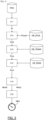
- the method comprises an acquisition step ET1 of Pv measurements of a plurality of power parameters PARi of the propulsion chain 2.
- Pv measurements are expressed according to different quantities.
- the acquisition step ET1 is carried out in a known manner using sensors of different types which are connected to the engine computer CAL.
- the method includes a step ET2 of comparing each measurement Pv to a power threshold Pseuil, determined respectively for each power parameter PAR, so as to deduce a gross power margin Pmb for said power parameter PAR.
- each power parameter PARi is associated with a power threshold Pseuil in a threshold database DB_SEUIL.
- the DB_SEUIL threshold database is accessible by the CAL engine computer which can thus determine the gross power margin Pmb for each PAR power parameter.
- the power thresholds Pseuil are independent of the operating points of the propulsion chain. Such an independence property is advantageous so that the calculated power margins have a predictive value (and therefore independent of future aircraft maneuvers and, consequently, independent of future operating points of the propulsion chain).
- each power threshold Pseuil is specific to a power parameter PARi in said hybrid propulsion chain and, preferably, specific to said operating point and to the operating configuration.
- each power parameter PARi is associated with a power threshold Pseuil for each operating point and each operating configuration in the threshold database DB_SEUIL.
- said power threshold Pseuil is expressed in the same magnitude as the measurement Pv, which allows, by simple difference calculation, to determine the gross power margin Pmb expressed in the same magnitude.
- Calculating an overall TAG power margin can be complex, particularly in the presence of series-parallel architectures where a significant portion of power is taken from both a free turbine and a gas generator.
- the pilot then needs to know the power margin available on each of the two branches in order to be able to adjust his demand accordingly.
- the free turbine of the TAG gas turbine provides mechanical power to the propulsion elements H1-H4 and where the electrical power is extracted from the TAG gas generator.
- the method comprises a step of converting ET3, from a database of transformation ratios DB_TRANSF, of the raw power margins Pmb of said power parameters PARi into refined power margins Pma expressed according to the same common quantity.
- the raw power margins Pmb are expressed in different quantities (Newton meters, amperes or degrees)
- the refined power margins Pma are all expressed in the same quantity, which allows them to be treated together.
- the refined power margins Pma are all expressed in the same homogeneous quantity.
- This homogeneous quantity is preferably expressed in Watts because it makes it possible to determine a power for the propulsion elements H1-H4. It goes without saying that the homogeneous quantity could be different, in particular, a couple or amperes.
- the transformation ratio database DB_TRANS is specific to the hybrid propulsion chain 2 and determines the transformation ratios between the power parameters PARi between them.
- the transformation ratios are determined theoretically by energy modeling of the hybrid propulsion chain 2.
- each transformation ratio is in the form of at least one mathematical equation which depends on the operating point and of the configuration of the hybrid propulsion chain 2. We can thus determine the impact caused by a variation in current or temperature on a channel in terms of torque on the propulsion elements H1-H4.
- the transformation ratio database DB_TRANS is stored in the CAL engine computer in the form of table(s).
- the gross current margin delivered by each electric generator GENA, GENB and the gross temperature margin of each electric motor M1A-M4A, M1B-M4B are respectively transformed into refined power margins Pma which are expressed in watts.
- the method comprises a step of transposition ET4, from a database of yield reports DB_REND, of the refined power margins Pma, hereinafter referred to as "refined margins Pma", for each power parameter PARi into normalized margins of power Pmn at one or more reference points of the propulsion chain 2, hereinafter referred to as “standardized margins Pmn”.
- the DB_REND efficiency ratios are independent of the operating points of the propulsion chain.
- the reference points are chosen to be the most as close as possible to where the power is really useful for piloting the aircraft, that is to say as close as possible to the propulsion elements H1-H4.
- a preferred reference point is for example the mechanical power available on the propulsion elements H1-H4. It nevertheless goes without saying that the reference points could be chosen differently depending on the needs or the specificity of the propulsion chain 2.
- the efficiency database DB_REND is specific to the propulsion chain 2 and determines the efficiency ratios between the power parameters between them, in particular as a function of the transmission elements between an acquisition point and a point of transmission. reference.
- the efficiency ratios are determined theoretically by energy modeling of the hybrid propulsion chain 2.
- each efficiency ratio is in the form of at least one mathematical equation which depends on the operating point and of the configuration of the hybrid propulsion chain 2. We can thus transpose a refined margin Pma obtained at a given point of the hybrid propulsion chain 2 into the same reference point in order to determine the real margin for said reference point.
- the DB_REND efficiency database is stored in the CAL motor computer in the form of table(s) which may depend on other measured parameters, for example, the average current level and the channel voltage.
- a refined torque margin Pma of the TAG gas turbine is transposed with an efficiency factor of 80% (90%*95%*93%) on the drive shafts of the propulsion elements H1-H4 to determine the margin normalized Pmn.
- a refined power margin Pma of the BATA-BATB battery is transposed with an efficiency factor of 88% (95%*93%) on the drive shafts of the propulsion elements H1-H4 to determine the normalized margin Pmn.
- the method includes a step of determining ET5 a source power margin for each reference point and a consumer power margin for each reference point.
- Power margins for sources and consumers have been presented, but it goes without saying that power margins could also be calculated for power transfer devices, for example, an electric cable or a transmission shaft.
- the power margins are determined for each propulsion element H1-H4.
- the source power margin is obtained by adding the normalized margins of the sources powering said propulsion element, namely, the BATA, BATB batteries and the TAG gas turbine. in our example.
- the MIndS source power margin depends on the distribution of sources on the propulsion elements as well as the configuration of the hybrid propulsion chain (availability or unavailability of sources). When power sources power only part of the propulsion elements H1-H4, the one which has the lowest standardized margin is selected.
- the individual consumer power margin MIndC is obtained by adding the normalized margins of the consumers drawing power at the reference point, namely, motors M1A-M4A, M1B-M4B .
- a selection step ET6 is carried out for the minimum individual power margin between the individual consumer power margin MIndC and the individual source power margin MIndS.
- the individual consumer power margin MIndC is limiting.
- the selection of individual MInd margins is carried out by going up the power chain supplying a given power element, by selecting the margins of the element offering the least power.
- a source can deliver 100kW and power two motors which can each provide 60kW.
- the power potentially available on each propeller is 60 kW, but the total power available is limited to 100 kW in total for the 2 propellers, because limited by the source.
- the individual margin of each propeller would be 50kW.
- An individual power margin MInd for each propulsion element H1-H4 informs the pilot of the propulsive power available to act on the attitude of the aircraft, thus contributing to the stabilization of the flight (e.g. the power margin on each engine on the right side provides information on the aircraft's ability to roll to the left).
- the pilot only needs to respect all the individual power margins to validate a piloting law.
- the total power received at a node is distributed in a weighted manner between the propulsion elements.
- the process selects the minimum torque margin of the TAG gas turbine.
- the process then transposes this overall margin from the TAG gas turbine to the propulsion elements H1-H4 by following the power chain and applying the successive efficiencies of each transmission member.
- a propulsion architecture is described in a nominal situation (without failure) where all the power sources (BATA batteries, BATB, TAG gas turbine) power all the propulsion elements H1-H4, there is therefore no not to select a power source that is more limiting than the others.
- the method uses the power margin of the immediately higher time horizon.
- TAG gas turbine PMD margin for MindCA_2 min margin calculation is used to calculate the MindCA_PMD margin.
- the PMC margin of the BATA, BATB batteries is used to calculate the MindCA_PMD margin.
- the different individual power margins can be displayed on the aircraft dashboard to inform the pilot of his power reserve and the maneuvers that can be performed.
- the different power margins can also be stored on the CAL engine computer in order to be used by an autopilot.
- the pilot is also aware that he will be able to carry out all the maneuvers he wants, without limitation, as long as he simultaneously maintains positive individual margins.
- the piloting system is configured to determine a piloting order O_PIL of the aircraft which is associated with a BP power requirement. Indeed, in a known manner, each O_PIL piloting order requires more or less power depending on the nature of the order (avoidance, takeoff, acceleration, etc.).
- the control method includes a step of determining at least one minimum power margin of the propulsion chain by a method as presented previously, in particular, the individual minimum power margin MInd.
- the control method includes a step of validation of the control order O_PIL if the power requirement BP is less than the minimum power margin MInd and, preferably, a step of rejection of the control order O_PIL if necessary in power BP is greater than the minimum power margin MInd.
Landscapes
- Engineering & Computer Science (AREA)
- Aviation & Aerospace Engineering (AREA)
- Mechanical Engineering (AREA)
- Electric Propulsion And Braking For Vehicles (AREA)
- Supply And Distribution Of Alternating Current (AREA)
- Control Of Eletrric Generators (AREA)
Claims (10)
- Verfahren zur Bestimmung mindestens eines minimalen Leistungsbereichs eines Hybridantriebsstrangs (2) für ein Transportfahrzeug, insbesondere ein Flugzeug, wobei der Antriebsstrang (2) eine Vielzahl von Leistungsquellen unterschiedlicher Art, eine Vielzahl von Leistungsverbrauchern und eine Vielzahl von Antriebselementen (H1-H4) umfasst, wobei jedes Antriebselement (H1-H4) mindestens einer Leistungsquelle und mindestens einem Leistungsverbraucher zugeordnet ist, wobei das Verfahren umfasst:• einen Schritt des Erfassens (ET1) von Messungen (Pv) einer Vielzahl von Leistungsparametern (PARi) des Hybridantriebsstrangs (2), wobei mindestens zwei Messungen (Pv) gemäß unterschiedlichen Größen ausgedrückt sind,• einen Schritt des Vergleichens (ET2) jeder Messung (Pv) mit mindestens einem Begrenzungsgrenzwert (Pseuil), der jeweils für jeden Leistungsparameter (PARi), ausgehend von einer Grenzwertdatenbank (DB_SEUIL) derart bestimmt wird, dass daraus mindestens ein Roh-Leistungsbereich (Pmb) für den Leistungsparameter (PARi) abgeleitet wird,• einen Schritt des Umwandelns (ET3), ausgehend von einer Transformationsdatenbank (DB_TRANS), der Roh-Leistungsbereiche (Pmb) der Leistungsparameter (PARi) in verfeinerte Leistungsbereiche (Pma), ausgedrückt gemäß einer gleichen gemeinsamen Größe,• einen Schritt des Überführens (ET4), ausgehend von einer Effizienzdatenbank (DB_REND), der verfeinerten Leistungsbereiche (Pma) in Standard-Leistungsbereiche (Pmn) an mindestens einem Bezugspunkt des Hybridantriebsstrangs (2), wobei die Effizienzdatenbank (DB_REND) die Effizienz der Übertragungsorgane zwischen einem Erfassungspunkt und einem Bezugspunkt bestimmt,• einen Schritt des Bestimmens (ET5) eines Quell-Leistungsbereichs (MlndS), ausgehend von den Standard-Leistungsbereichen (Pmn) der Quellen an dem Bezugspunkt, und eines Verbraucher-Leistungsbereichs (MlndC), ausgehend von den Standard-Leistungsbereichen (Pmn) der Verbraucher an dem Bezugspunkt,• einen Schritt des Bestimmens (ET6) des minimalen Leistungsbereichs (Mlnd) durch Auswahl des schwächsten Leistungsbereichs aus dem Verbraucher-Leistungsbereich (MlndC) und dem Quell-Leistungsbereich (MlndS) an dem Bezugspunkt.
- Verfahren nach Anspruch 1, wobei der oder die Bezugspunkte einem oder mehreren Antriebselementen (H1-H4) entsprechen.
- Verfahren nach einem der Ansprüche 1 bis 2, wobei, wenn eine Leistungsquelle mehrere Leistungsverbraucher parallel versorgt, hypothetisch angenommen wird, dass die in einem Knoten empfangene Gesamtleistung zwischen den Leistungsverbrauchern gleich verteilt wird.
- Verfahren nach einem der Ansprüche 1 bis 2, wobei, wenn eine Leistungsquelle mehrere Leistungsverbraucher parallel versorgt, die in einem Knoten empfangene Gesamtleistung zwischen den Leistungsverbrauchern gewichtet, vorzugsweise in Abhängigkeit von der Standardleistung jedes Verbrauchers, verteilt wird.
- Verfahren nach einem der Ansprüche 1 bis 4, wobei der Antriebsstrang (2) mindestens einen Turbogenerator (TG) und mindestens eine elektrische Batterie (BATA, BATB) als Leistungsquellen aufweist.
- Verfahren nach einem der Ansprüche 1 bis 5, wobei der Antriebsstrang (2) eine Vielzahl von Elektromotoren (M1A-M4A, M1B-M4B) als Leistungsverbraucher aufweist.
- Verfahren nach einem der Ansprüche 1 bis 6, wobei für ein Flugzeug die individuellen Leistungsbereiche (Mind) gemäß den Hauptachsen des Flugzeugs derart gruppiert sind, dass die Bereiche für Rollen, Neigen und Gieren angegeben werden.
- Methode zum Steuern eines Transportfahrzeugs, insbesondere eines Flugzeugs, aufweisend einen Hybridantriebsstrang, mittels eines Steuersystems, wobei die Methode umfasst:• einen Schritt des Bestimmens eines Lenkbefehls des Transportfahrzeugs durch das Lenksystem, wobei der Lenkbefehl einem Leistungsbedarf zugeordnet ist,• einen Schritt des Bestimmens mindestens eines minimalen Leistungsbereichs des Antriebsstrangs (2) durch ein Verfahren nach einem der Ansprüche 1 bis 7, und• einen Schritt des Bestätigens des Lenkbefehls, wenn der Leistungsbedarf unter dem minimalen Leistungsbereich liegt.
- Hybridantriebsstrang für Transportfahrzeug, insbesondere ein Flugzeug, wobei der Antriebsstrang (2) eine Vielzahl von Leistungsquellen unterschiedlicher Art, eine Vielzahl von Leistungsverbrauchern und eine Vielzahl von Antriebselementen (H1-H4) umfasst, wobei jedes Antriebselement (H1-H4) mindestens einer Leistungsquelle und mindestens einem Leistungsverbraucher zugeordnet ist, wobei der Antriebsstrang (2) mindestens einen Rechner (CAL) und Datenbanken (DB_SEUIL, DB_TRANS, DB_REND) umfasst, die von dem Rechner (CAL) erreichbar sind, wobei der Rechner (CAL) ausgelegt ist, um:• Messungen (Pv) einer Vielzahl von Leistungsparametern (PARi) des Hybridantriebsstrangs (2) zu erfassen (ET1), wobei mindestens zwei Messungen (Pv) gemäß unterschiedlichen Größen ausgedrückt sind,• jede Messung (Pv) mit mindestens einem Begrenzungsgrenzwert (Pseuil) zu vergleichen (ET2), der jeweils für jeden Leistungsparameter (PARi) ausgehend von einer Grenzwertdatenbank (DB_SEUIL) derart bestimmt wird, dass daraus mindestens ein Roh-Leistungsbereich (Pmb) für den Leistungsparameter (PARi) abgeleitet wird,• ausgehend von einer Transformationsdatenbank (DB_TRANS) Roh-Leistungsbereiche (Pmb) der Leistungsparameter (PARi) in verfeinerte Leistungsbereiche (Pma), ausgedrückt gemäß einer gleichen gemeinsamen Größe, umzuwandeln (ET3),• ausgehend von einer Effizienzdatenbank (DB_REND) verfeinerte Leistungsbereiche (Pma) in Standard-Leistungsbereiche (Pmn) an mindestens einem Bezugspunkt des Hybridantriebsstrangs (2) zu überführen (ET4), wobei die Effizienzdatenbank (DB_REND) die Effizienz der Übertragungsorgane zwischen einem Erfassungspunkt und einem Bezugspunkt bestimmt,• einen Quell-Leistungsbereich (MlndS), ausgehend von den Standard-Leistungsbereichen (Pmn) der Quellen an dem Bezugspunkt, und einen Verbraucher-Leistungsbereich (MlndC), ausgehend von den Standard-Leistungsbereichen (Pmn) der Verbraucher an dem Bezugspunkt, zu bestimmen (ET5),• den minimalen Leistungsbereich (Mlnd) durch Auswahl des schwächsten Leistungsbereichs aus dem Verbraucher-Leistungsbereich (MlndC) und dem Quell-Leistungsbereich (MlndS) an dem Bezugspunkt zu bestimmen (ET6).
- Transportfahrzeug, insbesondere Flugzeug, das mindestens einen Hybridantriebsstrang nach Anspruch 9 aufweist.
Applications Claiming Priority (2)
| Application Number | Priority Date | Filing Date | Title |
|---|---|---|---|
| FR2011522A FR3116044B1 (fr) | 2020-11-10 | 2020-11-10 | Procédé de détermination d’au moins une limite de puissance d’une chaine propulsive hybride pour véhicule de transport, en particulier, un aéronef |
| PCT/EP2021/080910 WO2022101129A1 (fr) | 2020-11-10 | 2021-11-08 | Procédé de détermination d'au moins une limite de puissance d'une chaine propulsive hybride pour véhicule de transport, en particulier, un aéronef |
Publications (2)
| Publication Number | Publication Date |
|---|---|
| EP4244136A1 EP4244136A1 (de) | 2023-09-20 |
| EP4244136B1 true EP4244136B1 (de) | 2024-02-14 |
Family
ID=74183384
Family Applications (1)
| Application Number | Title | Priority Date | Filing Date |
|---|---|---|---|
| EP21802372.9A Active EP4244136B1 (de) | 2020-11-10 | 2021-11-08 | Verfahren zur bestimmung mindestens einer leistungsgrenze eines hybridantriebsstrangs für ein transportfahrzeug, insbesondere ein flugzeug |
Country Status (6)
| Country | Link |
|---|---|
| EP (1) | EP4244136B1 (de) |
| CN (1) | CN116348378B (de) |
| CA (1) | CA3193847A1 (de) |
| FR (1) | FR3116044B1 (de) |
| PL (1) | PL4244136T3 (de) |
| WO (1) | WO2022101129A1 (de) |
Families Citing this family (2)
| Publication number | Priority date | Publication date | Assignee | Title |
|---|---|---|---|---|
| FR3138414A1 (fr) * | 2022-07-29 | 2024-02-02 | Safran Helicopter Engines | Surveillance d’un systeme propulsif d’un aeronef |
| CN117516952B (zh) * | 2023-11-09 | 2024-11-05 | 中国航发湖南动力机械研究所 | 一种航空燃气涡轮轴发动机功率保证检查方法 |
Family Cites Families (7)
| Publication number | Priority date | Publication date | Assignee | Title |
|---|---|---|---|---|
| FR2809082B1 (fr) * | 2000-05-17 | 2002-09-20 | Eurocopter France | Indicateur de marge de puissance pour un aeronef a voilure tournante, notamment un helicoptere |
| CN101327794A (zh) * | 2008-07-14 | 2008-12-24 | 北京理工大学 | 一种履带式混合动力车辆的功率后向控制方法 |
| FR2973340B1 (fr) * | 2011-03-30 | 2013-04-12 | Eurocopter France | Procede, dispositif d'aide au pilotage d'un aeronef, et aeronef |
| US9514628B2 (en) * | 2015-03-26 | 2016-12-06 | Bell Helicopter Textron Inc. | Electrical load monitoring system |
| FR3036235B1 (fr) * | 2015-05-15 | 2018-06-01 | Airbus Helicopters | Procede pour activer un moteur electrique d'une installation hybride d'un aeronef multimoteur et un aeronef |
| FR3086274B1 (fr) * | 2018-09-26 | 2021-03-12 | Airbus Helicopters | Procede et dispositif d'aide au pilotage d'un giravion hydride muni d'un rotor de sustentation et d'au moins un rotor propulsif generant une poussee |
| US10700632B1 (en) * | 2019-01-11 | 2020-06-30 | GM Global Technology Operations LLC | Method for motor and inverter temperature control |
-
2020
- 2020-11-10 FR FR2011522A patent/FR3116044B1/fr active Active
-
2021
- 2021-11-08 PL PL21802372.9T patent/PL4244136T3/pl unknown
- 2021-11-08 WO PCT/EP2021/080910 patent/WO2022101129A1/fr not_active Ceased
- 2021-11-08 CN CN202180069591.6A patent/CN116348378B/zh active Active
- 2021-11-08 CA CA3193847A patent/CA3193847A1/fr active Pending
- 2021-11-08 EP EP21802372.9A patent/EP4244136B1/de active Active
Also Published As
| Publication number | Publication date |
|---|---|
| CN116348378A (zh) | 2023-06-27 |
| EP4244136A1 (de) | 2023-09-20 |
| CA3193847A1 (fr) | 2022-05-19 |
| CN116348378B (zh) | 2025-08-29 |
| WO2022101129A1 (fr) | 2022-05-19 |
| US20230399122A1 (en) | 2023-12-14 |
| FR3116044A1 (fr) | 2022-05-13 |
| FR3116044B1 (fr) | 2022-12-30 |
| PL4244136T3 (pl) | 2024-05-06 |
Similar Documents
| Publication | Publication Date | Title |
|---|---|---|
| EP3599140B1 (de) | Verfahren und vorrichtung zur verwaltung der energie einer hybrid-triebwerksanlage eines multirotor-luftfahrzeugs | |
| EP3849908B1 (de) | Hybridantriebsanordnung für ein flugzeug | |
| CA2782456C (fr) | Procede de controle d'un groupe de moteurs et aeronef | |
| EP3095695B1 (de) | Betätigungsverfahren eines elektromotors einer hybridanlage eines mehrmotorigen luftfahrzeugs, und entsprechendes luftfahrzeug | |
| EP4244136B1 (de) | Verfahren zur bestimmung mindestens einer leistungsgrenze eines hybridantriebsstrangs für ein transportfahrzeug, insbesondere ein flugzeug | |
| CA3136789A1 (fr) | Systeme de propulsion hybride pour aeronef a decollage et atterrissage verticaux | |
| EP4274753B1 (de) | Luftfahrzeug mit hybrider energiequelle | |
| EP2885146B1 (de) | Verfahren zur begrenzung des drehmoments einer elektrischen maschine eines hybridfahrzeugs im falle des bedarfs an einem hohen drehmoment | |
| EP0782941A1 (de) | Verfahren und Vorrichtung zur Regelung der elektrischen Energieverteilung in einem Kraftfahrzeug, insbesondere mit Hybridantrieb | |
| FR3125019A1 (fr) | Architecture de génération électrique pour turbomachine hybridée | |
| WO2024099766A1 (fr) | Système de génération électrique pour un aéronef et procédé associé | |
| EP3953227B1 (de) | Verfahren und vorrichtung zur steuerung der hybridisierung eines flugzeugs | |
| EP2951904B1 (de) | Verfahren und system zur versorgung eines flugzeugs mit elektrischer energie | |
| EP4194333B1 (de) | Antriebsanlage für ein luftfahrzeug, luftfahrzeug und verfahren zum betreiben einer solchen anlage | |
| EP4507964B1 (de) | Luftfahrzeug mit hybrider energieversorgung | |
| EP3562704B1 (de) | Verfahren und system zum verwalten des ladevorgangs von modulen zum speichern elektrischer energie, wobei die module in einem elektrisch angetriebenen transportsystem verwendet werden | |
| EP4436876A1 (de) | Bereitstellung von energie in einem flugzeug mit regeldifferenzsteuerung | |
| EP4616506A1 (de) | Stromerzeugungssystem für ein flugzeug und zugehöriges verfahren | |
| US12617544B2 (en) | Method for determining at least one power limit of a hybrid drive train for a transport vehicle, in particular an aircraft | |
| EP1452383B1 (de) | Regelsystem für ein Kraftfahrzeuggetriebe | |
| EP4320721B1 (de) | Vorrichtung und verfahren zur steuerung mindestens eines elektromotors für eine flugzeugantriebsanordnung | |
| WO2021028123A1 (fr) | Procede de gestion d'un couple a fournir par un moteur electrique | |
| EP3947936B1 (de) | Verfahren und system zur steuerung eines nichtantriebsenergieerzeugungsturbinenmotors | |
| FR3143546A1 (fr) | Synchrophasage d’helices pour un aeronef |
Legal Events
| Date | Code | Title | Description |
|---|---|---|---|
| STAA | Information on the status of an ep patent application or granted ep patent |
Free format text: STATUS: UNKNOWN |
|
| STAA | Information on the status of an ep patent application or granted ep patent |
Free format text: STATUS: THE INTERNATIONAL PUBLICATION HAS BEEN MADE |
|
| PUAI | Public reference made under article 153(3) epc to a published international application that has entered the european phase |
Free format text: ORIGINAL CODE: 0009012 |
|
| STAA | Information on the status of an ep patent application or granted ep patent |
Free format text: STATUS: REQUEST FOR EXAMINATION WAS MADE |
|
| 17P | Request for examination filed |
Effective date: 20230326 |
|
| AK | Designated contracting states |
Kind code of ref document: A1 Designated state(s): AL AT BE BG CH CY CZ DE DK EE ES FI FR GB GR HR HU IE IS IT LI LT LU LV MC MK MT NL NO PL PT RO RS SE SI SK SM TR |
|
| GRAP | Despatch of communication of intention to grant a patent |
Free format text: ORIGINAL CODE: EPIDOSNIGR1 |
|
| STAA | Information on the status of an ep patent application or granted ep patent |
Free format text: STATUS: GRANT OF PATENT IS INTENDED |
|
| DAV | Request for validation of the european patent (deleted) | ||
| DAX | Request for extension of the european patent (deleted) | ||
| INTG | Intention to grant announced |
Effective date: 20231024 |
|
| GRAS | Grant fee paid |
Free format text: ORIGINAL CODE: EPIDOSNIGR3 |
|
| GRAA | (expected) grant |
Free format text: ORIGINAL CODE: 0009210 |
|
| STAA | Information on the status of an ep patent application or granted ep patent |
Free format text: STATUS: THE PATENT HAS BEEN GRANTED |
|
| AK | Designated contracting states |
Kind code of ref document: B1 Designated state(s): AL AT BE BG CH CY CZ DE DK EE ES FI FR GB GR HR HU IE IS IT LI LT LU LV MC MK MT NL NO PL PT RO RS SE SI SK SM TR |
|
| REG | Reference to a national code |
Ref country code: GB Ref legal event code: FG4D Free format text: NOT ENGLISH |
|
| REG | Reference to a national code |
Ref country code: CH Ref legal event code: EP |
|
| REG | Reference to a national code |
Ref country code: DE Ref legal event code: R096 Ref document number: 602021009458 Country of ref document: DE |
|
| REG | Reference to a national code |
Ref country code: IE Ref legal event code: FG4D Free format text: LANGUAGE OF EP DOCUMENT: FRENCH |
|
| REG | Reference to a national code |
Ref country code: LT Ref legal event code: MG9D |
|
| REG | Reference to a national code |
Ref country code: NL Ref legal event code: MP Effective date: 20240214 |
|
| PG25 | Lapsed in a contracting state [announced via postgrant information from national office to epo] |
Ref country code: IS Free format text: LAPSE BECAUSE OF FAILURE TO SUBMIT A TRANSLATION OF THE DESCRIPTION OR TO PAY THE FEE WITHIN THE PRESCRIBED TIME-LIMIT Effective date: 20240614 |
|
| PG25 | Lapsed in a contracting state [announced via postgrant information from national office to epo] |
Ref country code: LT Free format text: LAPSE BECAUSE OF FAILURE TO SUBMIT A TRANSLATION OF THE DESCRIPTION OR TO PAY THE FEE WITHIN THE PRESCRIBED TIME-LIMIT Effective date: 20240214 |
|
| PG25 | Lapsed in a contracting state [announced via postgrant information from national office to epo] |
Ref country code: GR Free format text: LAPSE BECAUSE OF FAILURE TO SUBMIT A TRANSLATION OF THE DESCRIPTION OR TO PAY THE FEE WITHIN THE PRESCRIBED TIME-LIMIT Effective date: 20240515 |
|
| REG | Reference to a national code |
Ref country code: AT Ref legal event code: MK05 Ref document number: 1656866 Country of ref document: AT Kind code of ref document: T Effective date: 20240214 |
|
| PG25 | Lapsed in a contracting state [announced via postgrant information from national office to epo] |
Ref country code: HR Free format text: LAPSE BECAUSE OF FAILURE TO SUBMIT A TRANSLATION OF THE DESCRIPTION OR TO PAY THE FEE WITHIN THE PRESCRIBED TIME-LIMIT Effective date: 20240214 Ref country code: RS Free format text: LAPSE BECAUSE OF FAILURE TO SUBMIT A TRANSLATION OF THE DESCRIPTION OR TO PAY THE FEE WITHIN THE PRESCRIBED TIME-LIMIT Effective date: 20240514 Ref country code: NL Free format text: LAPSE BECAUSE OF FAILURE TO SUBMIT A TRANSLATION OF THE DESCRIPTION OR TO PAY THE FEE WITHIN THE PRESCRIBED TIME-LIMIT Effective date: 20240214 |
|
| PG25 | Lapsed in a contracting state [announced via postgrant information from national office to epo] |
Ref country code: ES Free format text: LAPSE BECAUSE OF FAILURE TO SUBMIT A TRANSLATION OF THE DESCRIPTION OR TO PAY THE FEE WITHIN THE PRESCRIBED TIME-LIMIT Effective date: 20240214 |
|
| PG25 | Lapsed in a contracting state [announced via postgrant information from national office to epo] |
Ref country code: AT Free format text: LAPSE BECAUSE OF FAILURE TO SUBMIT A TRANSLATION OF THE DESCRIPTION OR TO PAY THE FEE WITHIN THE PRESCRIBED TIME-LIMIT Effective date: 20240214 |
|
| PG25 | Lapsed in a contracting state [announced via postgrant information from national office to epo] |
Ref country code: RS Free format text: LAPSE BECAUSE OF FAILURE TO SUBMIT A TRANSLATION OF THE DESCRIPTION OR TO PAY THE FEE WITHIN THE PRESCRIBED TIME-LIMIT Effective date: 20240514 Ref country code: NO Free format text: LAPSE BECAUSE OF FAILURE TO SUBMIT A TRANSLATION OF THE DESCRIPTION OR TO PAY THE FEE WITHIN THE PRESCRIBED TIME-LIMIT Effective date: 20240514 Ref country code: NL Free format text: LAPSE BECAUSE OF FAILURE TO SUBMIT A TRANSLATION OF THE DESCRIPTION OR TO PAY THE FEE WITHIN THE PRESCRIBED TIME-LIMIT Effective date: 20240214 Ref country code: LT Free format text: LAPSE BECAUSE OF FAILURE TO SUBMIT A TRANSLATION OF THE DESCRIPTION OR TO PAY THE FEE WITHIN THE PRESCRIBED TIME-LIMIT Effective date: 20240214 Ref country code: IS Free format text: LAPSE BECAUSE OF FAILURE TO SUBMIT A TRANSLATION OF THE DESCRIPTION OR TO PAY THE FEE WITHIN THE PRESCRIBED TIME-LIMIT Effective date: 20240614 Ref country code: HR Free format text: LAPSE BECAUSE OF FAILURE TO SUBMIT A TRANSLATION OF THE DESCRIPTION OR TO PAY THE FEE WITHIN THE PRESCRIBED TIME-LIMIT Effective date: 20240214 Ref country code: GR Free format text: LAPSE BECAUSE OF FAILURE TO SUBMIT A TRANSLATION OF THE DESCRIPTION OR TO PAY THE FEE WITHIN THE PRESCRIBED TIME-LIMIT Effective date: 20240515 Ref country code: FI Free format text: LAPSE BECAUSE OF FAILURE TO SUBMIT A TRANSLATION OF THE DESCRIPTION OR TO PAY THE FEE WITHIN THE PRESCRIBED TIME-LIMIT Effective date: 20240214 Ref country code: ES Free format text: LAPSE BECAUSE OF FAILURE TO SUBMIT A TRANSLATION OF THE DESCRIPTION OR TO PAY THE FEE WITHIN THE PRESCRIBED TIME-LIMIT Effective date: 20240214 Ref country code: BG Free format text: LAPSE BECAUSE OF FAILURE TO SUBMIT A TRANSLATION OF THE DESCRIPTION OR TO PAY THE FEE WITHIN THE PRESCRIBED TIME-LIMIT Effective date: 20240214 Ref country code: AT Free format text: LAPSE BECAUSE OF FAILURE TO SUBMIT A TRANSLATION OF THE DESCRIPTION OR TO PAY THE FEE WITHIN THE PRESCRIBED TIME-LIMIT Effective date: 20240214 |
|
| PG25 | Lapsed in a contracting state [announced via postgrant information from national office to epo] |
Ref country code: PT Free format text: LAPSE BECAUSE OF FAILURE TO SUBMIT A TRANSLATION OF THE DESCRIPTION OR TO PAY THE FEE WITHIN THE PRESCRIBED TIME-LIMIT Effective date: 20240614 |
|
| PG25 | Lapsed in a contracting state [announced via postgrant information from national office to epo] |
Ref country code: SE Free format text: LAPSE BECAUSE OF FAILURE TO SUBMIT A TRANSLATION OF THE DESCRIPTION OR TO PAY THE FEE WITHIN THE PRESCRIBED TIME-LIMIT Effective date: 20240214 Ref country code: PT Free format text: LAPSE BECAUSE OF FAILURE TO SUBMIT A TRANSLATION OF THE DESCRIPTION OR TO PAY THE FEE WITHIN THE PRESCRIBED TIME-LIMIT Effective date: 20240614 Ref country code: LV Free format text: LAPSE BECAUSE OF FAILURE TO SUBMIT A TRANSLATION OF THE DESCRIPTION OR TO PAY THE FEE WITHIN THE PRESCRIBED TIME-LIMIT Effective date: 20240214 |
|
| PG25 | Lapsed in a contracting state [announced via postgrant information from national office to epo] |
Ref country code: DK Free format text: LAPSE BECAUSE OF FAILURE TO SUBMIT A TRANSLATION OF THE DESCRIPTION OR TO PAY THE FEE WITHIN THE PRESCRIBED TIME-LIMIT Effective date: 20240214 |
|
| PG25 | Lapsed in a contracting state [announced via postgrant information from national office to epo] |
Ref country code: SM Free format text: LAPSE BECAUSE OF FAILURE TO SUBMIT A TRANSLATION OF THE DESCRIPTION OR TO PAY THE FEE WITHIN THE PRESCRIBED TIME-LIMIT Effective date: 20240214 |
|
| PG25 | Lapsed in a contracting state [announced via postgrant information from national office to epo] |
Ref country code: EE Free format text: LAPSE BECAUSE OF FAILURE TO SUBMIT A TRANSLATION OF THE DESCRIPTION OR TO PAY THE FEE WITHIN THE PRESCRIBED TIME-LIMIT Effective date: 20240214 |
|
| PG25 | Lapsed in a contracting state [announced via postgrant information from national office to epo] |
Ref country code: SK Free format text: LAPSE BECAUSE OF FAILURE TO SUBMIT A TRANSLATION OF THE DESCRIPTION OR TO PAY THE FEE WITHIN THE PRESCRIBED TIME-LIMIT Effective date: 20240214 |
|
| PG25 | Lapsed in a contracting state [announced via postgrant information from national office to epo] |
Ref country code: SM Free format text: LAPSE BECAUSE OF FAILURE TO SUBMIT A TRANSLATION OF THE DESCRIPTION OR TO PAY THE FEE WITHIN THE PRESCRIBED TIME-LIMIT Effective date: 20240214 Ref country code: SK Free format text: LAPSE BECAUSE OF FAILURE TO SUBMIT A TRANSLATION OF THE DESCRIPTION OR TO PAY THE FEE WITHIN THE PRESCRIBED TIME-LIMIT Effective date: 20240214 Ref country code: RO Free format text: LAPSE BECAUSE OF FAILURE TO SUBMIT A TRANSLATION OF THE DESCRIPTION OR TO PAY THE FEE WITHIN THE PRESCRIBED TIME-LIMIT Effective date: 20240214 Ref country code: EE Free format text: LAPSE BECAUSE OF FAILURE TO SUBMIT A TRANSLATION OF THE DESCRIPTION OR TO PAY THE FEE WITHIN THE PRESCRIBED TIME-LIMIT Effective date: 20240214 Ref country code: DK Free format text: LAPSE BECAUSE OF FAILURE TO SUBMIT A TRANSLATION OF THE DESCRIPTION OR TO PAY THE FEE WITHIN THE PRESCRIBED TIME-LIMIT Effective date: 20240214 |
|
| REG | Reference to a national code |
Ref country code: DE Ref legal event code: R097 Ref document number: 602021009458 Country of ref document: DE |
|
| PLBE | No opposition filed within time limit |
Free format text: ORIGINAL CODE: 0009261 |
|
| STAA | Information on the status of an ep patent application or granted ep patent |
Free format text: STATUS: NO OPPOSITION FILED WITHIN TIME LIMIT |
|
| 26N | No opposition filed |
Effective date: 20241115 |
|
| PG25 | Lapsed in a contracting state [announced via postgrant information from national office to epo] |
Ref country code: SI Free format text: LAPSE BECAUSE OF FAILURE TO SUBMIT A TRANSLATION OF THE DESCRIPTION OR TO PAY THE FEE WITHIN THE PRESCRIBED TIME-LIMIT Effective date: 20240214 |
|
| REG | Reference to a national code |
Ref country code: CH Ref legal event code: PL |
|
| PG25 | Lapsed in a contracting state [announced via postgrant information from national office to epo] |
Ref country code: MC Free format text: LAPSE BECAUSE OF FAILURE TO SUBMIT A TRANSLATION OF THE DESCRIPTION OR TO PAY THE FEE WITHIN THE PRESCRIBED TIME-LIMIT Effective date: 20240214 |
|
| PG25 | Lapsed in a contracting state [announced via postgrant information from national office to epo] |
Ref country code: LU Free format text: LAPSE BECAUSE OF NON-PAYMENT OF DUE FEES Effective date: 20241108 |
|
| REG | Reference to a national code |
Ref country code: CH Ref legal event code: PL |
|
| PG25 | Lapsed in a contracting state [announced via postgrant information from national office to epo] |
Ref country code: CH Free format text: LAPSE BECAUSE OF NON-PAYMENT OF DUE FEES Effective date: 20241130 |
|
| REG | Reference to a national code |
Ref country code: BE Ref legal event code: MM Effective date: 20241130 |
|
| PG25 | Lapsed in a contracting state [announced via postgrant information from national office to epo] |
Ref country code: BE Free format text: LAPSE BECAUSE OF NON-PAYMENT OF DUE FEES Effective date: 20241130 |
|
| PG25 | Lapsed in a contracting state [announced via postgrant information from national office to epo] |
Ref country code: IE Free format text: LAPSE BECAUSE OF NON-PAYMENT OF DUE FEES Effective date: 20241108 |
|
| PGFP | Annual fee paid to national office [announced via postgrant information from national office to epo] |
Ref country code: DE Payment date: 20251118 Year of fee payment: 5 |
|
| PGFP | Annual fee paid to national office [announced via postgrant information from national office to epo] |
Ref country code: GB Payment date: 20251125 Year of fee payment: 5 |
|
| PGFP | Annual fee paid to national office [announced via postgrant information from national office to epo] |
Ref country code: IT Payment date: 20251128 Year of fee payment: 5 |
|
| PGFP | Annual fee paid to national office [announced via postgrant information from national office to epo] |
Ref country code: FR Payment date: 20251125 Year of fee payment: 5 |
|
| PGFP | Annual fee paid to national office [announced via postgrant information from national office to epo] |
Ref country code: CZ Payment date: 20251024 Year of fee payment: 5 |
|
| PGFP | Annual fee paid to national office [announced via postgrant information from national office to epo] |
Ref country code: PL Payment date: 20251029 Year of fee payment: 5 |
|
| PG25 | Lapsed in a contracting state [announced via postgrant information from national office to epo] |
Ref country code: HU Free format text: LAPSE BECAUSE OF FAILURE TO SUBMIT A TRANSLATION OF THE DESCRIPTION OR TO PAY THE FEE WITHIN THE PRESCRIBED TIME-LIMIT; INVALID AB INITIO Effective date: 20211108 |
|
| PG25 | Lapsed in a contracting state [announced via postgrant information from national office to epo] |
Ref country code: CY Free format text: LAPSE BECAUSE OF FAILURE TO SUBMIT A TRANSLATION OF THE DESCRIPTION OR TO PAY THE FEE WITHIN THE PRESCRIBED TIME-LIMIT; INVALID AB INITIO Effective date: 20211108 |