EP4274753B1 - Luftfahrzeug mit hybrider energiequelle - Google Patents
Luftfahrzeug mit hybrider energiequelle Download PDFInfo
- Publication number
- EP4274753B1 EP4274753B1 EP22703015.2A EP22703015A EP4274753B1 EP 4274753 B1 EP4274753 B1 EP 4274753B1 EP 22703015 A EP22703015 A EP 22703015A EP 4274753 B1 EP4274753 B1 EP 4274753B1
- Authority
- EP
- European Patent Office
- Prior art keywords
- power
- sources
- vertical drive
- drive units
- horizontal drive
- Prior art date
- Legal status (The legal status is an assumption and is not a legal conclusion. Google has not performed a legal analysis and makes no representation as to the accuracy of the status listed.)
- Active
Links
Images


Classifications
-
- H—ELECTRICITY
- H02—GENERATION; CONVERSION OR DISTRIBUTION OF ELECTRIC POWER
- H02J—CIRCUIT ARRANGEMENTS OR SYSTEMS FOR SUPPLYING OR DISTRIBUTING ELECTRIC POWER; SYSTEMS FOR STORING ELECTRIC ENERGY
- H02J1/00—Circuit arrangements for DC mains or DC distribution networks
- H02J1/08—Three-wire systems; Systems having more than three wires
- H02J1/084—Three-wire systems; Systems having more than three wires for selectively connecting the load or loads to one or several among a plurality of power lines or power sources
- H02J1/086—Three-wire systems; Systems having more than three wires for selectively connecting the load or loads to one or several among a plurality of power lines or power sources for providing alternative feeding paths between load or loads and source or sources when the main path fails
-
- B—PERFORMING OPERATIONS; TRANSPORTING
- B64—AIRCRAFT; AVIATION; COSMONAUTICS
- B64D—EQUIPMENT FOR FITTING IN OR TO AIRCRAFT; FLIGHT SUITS; PARACHUTES; ARRANGEMENT OR MOUNTING OF POWER PLANTS OR PROPULSION TRANSMISSIONS IN AIRCRAFT
- B64D27/00—Arrangement or mounting of power plants in aircraft; Aircraft characterised by the type or position of power plants
- B64D27/02—Aircraft characterised by the type or position of power plants
- B64D27/30—Aircraft characterised by electric power plants
- B64D27/33—Hybrid electric aircraft
-
- B—PERFORMING OPERATIONS; TRANSPORTING
- B64—AIRCRAFT; AVIATION; COSMONAUTICS
- B64C—AEROPLANES; HELICOPTERS
- B64C29/00—Aircraft capable of landing or taking-off vertically, e.g. vertical take-off and landing [VTOL] aircraft
- B64C29/0008—Aircraft capable of landing or taking-off vertically, e.g. vertical take-off and landing [VTOL] aircraft having its flight directional axis horizontal when grounded
- B64C29/0016—Aircraft capable of landing or taking-off vertically, e.g. vertical take-off and landing [VTOL] aircraft having its flight directional axis horizontal when grounded the lift during taking-off being created by free or ducted propellers or by blowers
- B64C29/0025—Aircraft capable of landing or taking-off vertically, e.g. vertical take-off and landing [VTOL] aircraft having its flight directional axis horizontal when grounded the lift during taking-off being created by free or ducted propellers or by blowers the propellers being fixed relative to the fuselage
-
- B—PERFORMING OPERATIONS; TRANSPORTING
- B64—AIRCRAFT; AVIATION; COSMONAUTICS
- B64D—EQUIPMENT FOR FITTING IN OR TO AIRCRAFT; FLIGHT SUITS; PARACHUTES; ARRANGEMENT OR MOUNTING OF POWER PLANTS OR PROPULSION TRANSMISSIONS IN AIRCRAFT
- B64D27/00—Arrangement or mounting of power plants in aircraft; Aircraft characterised by the type or position of power plants
- B64D27/02—Aircraft characterised by the type or position of power plants
- B64D27/24—Aircraft characterised by the type or position of power plants using steam or spring force
-
- B—PERFORMING OPERATIONS; TRANSPORTING
- B64—AIRCRAFT; AVIATION; COSMONAUTICS
- B64D—EQUIPMENT FOR FITTING IN OR TO AIRCRAFT; FLIGHT SUITS; PARACHUTES; ARRANGEMENT OR MOUNTING OF POWER PLANTS OR PROPULSION TRANSMISSIONS IN AIRCRAFT
- B64D27/00—Arrangement or mounting of power plants in aircraft; Aircraft characterised by the type or position of power plants
- B64D27/02—Aircraft characterised by the type or position of power plants
- B64D27/30—Aircraft characterised by electric power plants
- B64D27/35—Arrangements for on-board electric energy production, distribution, recovery or storage
- B64D27/355—Arrangements for on-board electric energy production, distribution, recovery or storage using fuel cells
-
- B—PERFORMING OPERATIONS; TRANSPORTING
- B64—AIRCRAFT; AVIATION; COSMONAUTICS
- B64D—EQUIPMENT FOR FITTING IN OR TO AIRCRAFT; FLIGHT SUITS; PARACHUTES; ARRANGEMENT OR MOUNTING OF POWER PLANTS OR PROPULSION TRANSMISSIONS IN AIRCRAFT
- B64D27/00—Arrangement or mounting of power plants in aircraft; Aircraft characterised by the type or position of power plants
- B64D27/02—Aircraft characterised by the type or position of power plants
- B64D27/30—Aircraft characterised by electric power plants
- B64D27/35—Arrangements for on-board electric energy production, distribution, recovery or storage
- B64D27/357—Arrangements for on-board electric energy production, distribution, recovery or storage using batteries
-
- B—PERFORMING OPERATIONS; TRANSPORTING
- B64—AIRCRAFT; AVIATION; COSMONAUTICS
- B64D—EQUIPMENT FOR FITTING IN OR TO AIRCRAFT; FLIGHT SUITS; PARACHUTES; ARRANGEMENT OR MOUNTING OF POWER PLANTS OR PROPULSION TRANSMISSIONS IN AIRCRAFT
- B64D31/00—Power plant control systems; Arrangement of power plant control systems in aircraft
- B64D31/16—Power plant control systems; Arrangement of power plant control systems in aircraft for electric power plants
- B64D31/18—Power plant control systems; Arrangement of power plant control systems in aircraft for electric power plants for hybrid-electric power plants
-
- B—PERFORMING OPERATIONS; TRANSPORTING
- B64—AIRCRAFT; AVIATION; COSMONAUTICS
- B64U—UNMANNED AERIAL VEHICLES [UAV]; EQUIPMENT THEREFOR
- B64U30/00—Means for producing lift; Empennages; Arrangements thereof
- B64U30/20—Rotors; Rotor supports
-
- B—PERFORMING OPERATIONS; TRANSPORTING
- B64—AIRCRAFT; AVIATION; COSMONAUTICS
- B64U—UNMANNED AERIAL VEHICLES [UAV]; EQUIPMENT THEREFOR
- B64U50/00—Propulsion; Power supply
- B64U50/10—Propulsion
- B64U50/13—Propulsion using external fans or propellers
-
- B—PERFORMING OPERATIONS; TRANSPORTING
- B64—AIRCRAFT; AVIATION; COSMONAUTICS
- B64U—UNMANNED AERIAL VEHICLES [UAV]; EQUIPMENT THEREFOR
- B64U50/00—Propulsion; Power supply
- B64U50/10—Propulsion
- B64U50/13—Propulsion using external fans or propellers
- B64U50/14—Propulsion using external fans or propellers ducted or shrouded
-
- B—PERFORMING OPERATIONS; TRANSPORTING
- B64—AIRCRAFT; AVIATION; COSMONAUTICS
- B64U—UNMANNED AERIAL VEHICLES [UAV]; EQUIPMENT THEREFOR
- B64U50/00—Propulsion; Power supply
- B64U50/10—Propulsion
- B64U50/19—Propulsion using electrically powered motors
-
- B—PERFORMING OPERATIONS; TRANSPORTING
- B64—AIRCRAFT; AVIATION; COSMONAUTICS
- B64U—UNMANNED AERIAL VEHICLES [UAV]; EQUIPMENT THEREFOR
- B64U50/00—Propulsion; Power supply
- B64U50/30—Supply or distribution of electrical power
-
- H—ELECTRICITY
- H02—GENERATION; CONVERSION OR DISTRIBUTION OF ELECTRIC POWER
- H02J—CIRCUIT ARRANGEMENTS OR SYSTEMS FOR SUPPLYING OR DISTRIBUTING ELECTRIC POWER; SYSTEMS FOR STORING ELECTRIC ENERGY
- H02J1/00—Circuit arrangements for DC mains or DC distribution networks
- H02J1/08—Three-wire systems; Systems having more than three wires
- H02J1/084—Three-wire systems; Systems having more than three wires for selectively connecting the load or loads to one or several among a plurality of power lines or power sources
-
- H—ELECTRICITY
- H02—GENERATION; CONVERSION OR DISTRIBUTION OF ELECTRIC POWER
- H02J—CIRCUIT ARRANGEMENTS OR SYSTEMS FOR SUPPLYING OR DISTRIBUTING ELECTRIC POWER; SYSTEMS FOR STORING ELECTRIC ENERGY
- H02J1/00—Circuit arrangements for DC mains or DC distribution networks
- H02J1/10—Parallel operation of DC sources
- H02J1/102—Parallel operation of DC sources being switching converters
-
- H—ELECTRICITY
- H02—GENERATION; CONVERSION OR DISTRIBUTION OF ELECTRIC POWER
- H02J—CIRCUIT ARRANGEMENTS OR SYSTEMS FOR SUPPLYING OR DISTRIBUTING ELECTRIC POWER; SYSTEMS FOR STORING ELECTRIC ENERGY
- H02J1/00—Circuit arrangements for DC mains or DC distribution networks
- H02J1/10—Parallel operation of DC sources
- H02J1/12—Parallel operation of DC generators with converters, e.g. with mercury-arc rectifier
-
- H—ELECTRICITY
- H02—GENERATION; CONVERSION OR DISTRIBUTION OF ELECTRIC POWER
- H02J—CIRCUIT ARRANGEMENTS OR SYSTEMS FOR SUPPLYING OR DISTRIBUTING ELECTRIC POWER; SYSTEMS FOR STORING ELECTRIC ENERGY
- H02J7/00—Circuit arrangements for charging or depolarising batteries or for supplying loads from batteries
- H02J7/14—Circuit arrangements for charging or depolarising batteries or for supplying loads from batteries for charging batteries from dynamo-electric generators driven at varying speed, e.g. on vehicle
- H02J7/1423—Circuit arrangements for charging or depolarising batteries or for supplying loads from batteries for charging batteries from dynamo-electric generators driven at varying speed, e.g. on vehicle with multiple batteries
-
- H—ELECTRICITY
- H02—GENERATION; CONVERSION OR DISTRIBUTION OF ELECTRIC POWER
- H02J—CIRCUIT ARRANGEMENTS OR SYSTEMS FOR SUPPLYING OR DISTRIBUTING ELECTRIC POWER; SYSTEMS FOR STORING ELECTRIC ENERGY
- H02J7/00—Circuit arrangements for charging or depolarising batteries or for supplying loads from batteries
- H02J7/14—Circuit arrangements for charging or depolarising batteries or for supplying loads from batteries for charging batteries from dynamo-electric generators driven at varying speed, e.g. on vehicle
- H02J7/143—Circuit arrangements for charging or depolarising batteries or for supplying loads from batteries for charging batteries from dynamo-electric generators driven at varying speed, e.g. on vehicle with multiple generators
-
- H—ELECTRICITY
- H02—GENERATION; CONVERSION OR DISTRIBUTION OF ELECTRIC POWER
- H02J—CIRCUIT ARRANGEMENTS OR SYSTEMS FOR SUPPLYING OR DISTRIBUTING ELECTRIC POWER; SYSTEMS FOR STORING ELECTRIC ENERGY
- H02J7/00—Circuit arrangements for charging or depolarising batteries or for supplying loads from batteries
- H02J7/14—Circuit arrangements for charging or depolarising batteries or for supplying loads from batteries for charging batteries from dynamo-electric generators driven at varying speed, e.g. on vehicle
- H02J7/1438—Circuit arrangements for charging or depolarising batteries or for supplying loads from batteries for charging batteries from dynamo-electric generators driven at varying speed, e.g. on vehicle in combination with power supplies for loads other than batteries
-
- B—PERFORMING OPERATIONS; TRANSPORTING
- B64—AIRCRAFT; AVIATION; COSMONAUTICS
- B64D—EQUIPMENT FOR FITTING IN OR TO AIRCRAFT; FLIGHT SUITS; PARACHUTES; ARRANGEMENT OR MOUNTING OF POWER PLANTS OR PROPULSION TRANSMISSIONS IN AIRCRAFT
- B64D2221/00—Electric power distribution systems onboard aircraft
-
- B—PERFORMING OPERATIONS; TRANSPORTING
- B64—AIRCRAFT; AVIATION; COSMONAUTICS
- B64D—EQUIPMENT FOR FITTING IN OR TO AIRCRAFT; FLIGHT SUITS; PARACHUTES; ARRANGEMENT OR MOUNTING OF POWER PLANTS OR PROPULSION TRANSMISSIONS IN AIRCRAFT
- B64D27/00—Arrangement or mounting of power plants in aircraft; Aircraft characterised by the type or position of power plants
- B64D27/02—Aircraft characterised by the type or position of power plants
- B64D27/026—Aircraft characterised by the type or position of power plants comprising different types of power plants, e.g. combination of a piston engine and a gas-turbine
-
- H02J2105/32—
-
- Y—GENERAL TAGGING OF NEW TECHNOLOGICAL DEVELOPMENTS; GENERAL TAGGING OF CROSS-SECTIONAL TECHNOLOGIES SPANNING OVER SEVERAL SECTIONS OF THE IPC; TECHNICAL SUBJECTS COVERED BY FORMER USPC CROSS-REFERENCE ART COLLECTIONS [XRACs] AND DIGESTS
- Y02—TECHNOLOGIES OR APPLICATIONS FOR MITIGATION OR ADAPTATION AGAINST CLIMATE CHANGE
- Y02T—CLIMATE CHANGE MITIGATION TECHNOLOGIES RELATED TO TRANSPORTATION
- Y02T50/00—Aeronautics or air transport
- Y02T50/60—Efficient propulsion technologies, e.g. for aircraft
Definitions
- the invention relates to the field of aircraft and more particularly to the field of aircraft with electric motors and vertical take-off and landing.
- the aeronautics sector is currently undergoing many upheavals, partly related to the evolution of environmental requirements, and partly related to the development of electrically powered aircraft.
- the field of VTOL Very Take-Off and Landing is particularly dynamic because it offers very interesting prospects as a new means of mobility.
- the document US 6,293,491 B1 discloses a hybrid power aircraft comprising two horizontal drive thrusters each powered by a respective electric motor, forming two respective horizontal drive groups; eight pairs of vertical take-off/landing rotors, each powered by a respective electric motor; a source of electricity, and two sources of electrical generation.
- Other hybrid power aircraft are known from the documents EP 3 296 212 A1 And FR 3 095 806 A1 .
- VTOLs are a fairly old field in themselves (they were developed as early as 1921), but their electrification has led to an explosion of new solutions proposed, as well as regulations.
- the latest regulations see for example SC-VTOL-01 SPECIAL CONDITION Vertical Take-Off and Landing (VTOL) Aircraft; issued on July 2, 2019) require redundancy of all systems related to propulsion and flight, from engines, to energy sources, through the entire electrical system to ensure continued safe flight and landing and not just an emergency landing following the occurrence of a failure. This is also called “one-fail-safe" in English, i.e. "tolerant to a single failure".
- the invention improves the situation. To this end, it proposes an aircraft with a hybrid energy source comprising at least two horizontal drive thrusters each powered by a respective electric motor, forming at least two respective horizontal drive groups, at least four pairs of vertical take-off/landing rotors each powered by a respective electric motor, and at least four sources of electricity each connected to a respective electric motor of a pair of vertical take-off/landing rotors, each pair of rotors forming with the respective electric motors and the corresponding source of electricity a vertical drive group, each vertical drive group comprising an electrical power supply bus whose output can be connected to a single horizontal drive group, the number of vertical drive groups being such that each horizontal drive group can be connected to at least two vertical drive groups via a respective switch arranged at the input of the horizontal drive group, at least two sources of electrical generation, each connected on the one hand to each of the electrical power supply buses by a respective input of the corresponding vertical drive group, and on the other hand to each drive group horizontal via the respective output of each vertical drive
- This aircraft is particularly advantageous because its architecture makes it possible to create redundancy guaranteeing one-fail-safe while optimizing the dimensioning of the elements.
- the aircraft according to the invention minimizes the additional costs related to the implementation of one-fail-safe and implements a truly hybrid architecture in which the electricity sources are truly complementary at each stage of the flight.
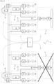
- an aircraft 2 comprises a control 4, two horizontal drive groups 6 and 8, four vertical drive groups 10, 12, 14 and 16, and two electrical generation sources 18 and 20.
- the horizontal drive unit 6 (respectively 8) comprises a direct current to alternating current converter 22 (respectively 32), an electric motor 24 (respectively 34) and a propeller 26 (respectively 36), for example a propeller.
- the propeller 26 (respectively 36) is arranged to allow the aircraft to move forward in a substantially horizontal direction.
- the propeller 26 (respectively 36) consumes a power of 80 kW in flight mode.
- the horizontal drive group 6 (respectively 8) is connected at the input to a switch 28 (respectively 38) which makes it possible to connect this input to the output of the vertical drive group 10 (respectively 14) or 12 (respectively 16), as described below.
- the vertical drive group 10 (respectively 12, 14, 16) comprises a rotor 42 (respectively 46, 72, 76) driven by a motor 52 (respectively 56, 82, 86), a rotor 44 (respectively 48, 74, 78) driven by a motor 54 (respectively 58, 84, 88).
- the motors 52 and 54 are powered by a respective direct current to alternating current converter 62 and 64 (respectively 66 and 68, 92 and 94, 96 and 98).
- the DC to AC converters 62 and 64 (respectively 66 and 68, 92 and 94, 96 and 98) are connected to an electrical bus of the vertical drive group 10 (respectively 12, 14, 16), to which a battery 50 (respectively 60, 80, 90) is connected as well as an input connected to an electrical bus for distributing the electrical generation source 18, an input connected to an electrical bus for distributing the electrical generation source 20.
- the electrical bus of each of the vertical drive groups 10 and 12 (respectively 14 and 16) is connected to a respective output of the latter, which is connected to the switch 28 (respectively 38).
- the 50, 60, 80 and 90 batteries together deliver 600kW when they deliver 100% of their capacity.
- each electrical generation source 18 comprises on the one hand a turbine generator 100 (respectively 102) and an alternating current to direct current converter 104 (respectively 106).
- Each turbine generator can deliver 40kW at 100% of its capacity.
- the sources of electrical generation could be other sources of electricity production, DC or AC followed by an AC to DC converter or a DC to DC converter.
- these sources could be based on turbogenerators powered by conventional fuel, biofuel, or synthetic fuels.
- a hydrogen-based energy source such as a fuel cell could be used.
- control 4 is a low voltage device arranged to control on the one hand the electrical generation sources 18 and 20, on the other hand the switches 28 and 38, as well as various protection elements not shown in the Figure 1 which will be explained further with the Figures 2 to 6 .
- the particular structure of the aircraft of the Figure 1 allows for a real hybridization of electrical energy sources, as opposed to existing solutions in which it is a juxtaposition.
- both the batteries and the electrical generation sources can operate in concert.
- this architecture allows the batteries to be treated as pure "energy buffers".
- the batteries are treated in a completely passive manner, without any need for software or hardware intelligence other than the basic intelligence required to make operate the battery system itself BMS (Battery Management System), for example to activate the protections and report the status.
- BMS Battery Management System
- FIG. 2 represents an energy consumption cycle during a flight with an aircraft of the Figure 1 .
- the flight begins with an initial operation 200 in which the aircraft takes off vertically.
- the rotors of the vertical drive units are operating and constitute the majority of the energy consumed - the horizontal drive units are likely to operate for stability reasons, but with negligible energy consumption. They are powered at 600kW by the batteries and at 80kW by the electrical generation sources. Thus, the batteries, filled between 75% and 90% at the beginning of the flight, drop to 55% to 70% of their capacity.
- the aircraft is about 50 feet from its take-off point, or about 15m of elevation.
- the aircraft gradually transitions from vertical to horizontal flight between 50 feet and 150 feet, and then the aircraft performs a climb similar to that of traditional aircraft.
- the rotors are gradually stopped, and the consumption drops from 680kW to 80kW once horizontal cruise is reached.
- the batteries and electrical generation sources continue to work at full capacity, and the batteries continue to drain, down to 10% to 30% when the horizontal cruise phase is reached.
- the horizontal flight is done in a 220 operation during which the batteries are not used.
- the electrical generation sources continue to operate at full speed and the 80kW they produce are shared between the horizontal drive groups which are controlled by the control, and the power not consumed by these The latter is used to recharge the batteries.
- This phase at an altitude of over 1000 feet (about 300m), allows the batteries to be recharged to about 50%.
- the transition from horizontal to vertical flight is then carried out in a 240 operation, in which the consumption gradually increases to approximately 340kW, and in which the battery charge gradually increases from 100% to between 85% and 95%.
- the vertical landing is carried out by using only the rotors, as for takeoff, but with the advantage of taking advantage of gravity.
- the batteries continue to discharge up to between 75% and 90%, as at the starting point of operation 200.
- the aircraft does not need to be recharged on the ground between two flights, which increases its usability.
- the electrical generation sources always operate at full capacity (there is an exception case that will appear with the Figure 6 ), and that the batteries are used to compensate for cases where the electrical generation sources cannot provide enough power.
- the batteries are recharged as much as possible to ensure that there is enough electrical energy to land.
- the aircraft batteries can be recharged on the ground between two flights sufficiently separated in time.
- the control 4 can make more sophisticated arbitrations on the power supply during the various phases, either to increase the operating points of the turbine generators to modify the distribution of energy supply and increase the range, limit noise pollution, pollutant emissions, etc.
- the battery control is managed passively thanks to the architecture of the invention - if the rotors or horizontal drive groups draw less than 80kW, then the batteries are naturally not called upon, and the surplus current can even be used to recharge them (as in the 220 or 230 operation); if more power is requested, then the batteries are naturally called upon.
- the oversizing of the batteries can be kept quite low thanks to the architecture of the invention. Indeed, it is no coincidence that there remains between 10% and 30% of charge in the batteries at the end of the 220 operation - this ensures that the one-fail-safe can be maintained with a failure eliminating a battery.
- FIG. 3 represents a case of failure of a battery or other electrical element of one of the vertical drive groups.
- the energy coming out of the electrical generation source 18 and the vertical drive group 12 are shown, but the other elements operate in a similar manner.
- the first vertical drive group 10 is switched off due to an electrical failure of one of the motors 52 or 54. This is particularly disabling during one of the operations 200, 210, 240 or 250.
- each electrical element is protected by a contactor that can be controlled to isolate it from the rest of the circuit.
- two contactors, not shown, at the inputs connected to the electrical distribution buses specific to each generation source make it possible to isolate the vertical drive group 10 (respectively 12, 14, 16) and to prevent any propagation of electrical problems from the outside to the vertical drive group 10 (respectively 12, 14, 16). This is also the case for the horizontal drive groups with the switches 28 and 38 as well as with the electrical generation sources with switches not shown.
- each element within these electrical subassemblies is also connected to the rest of the electrical subassembly to which it belongs by means of a switch not shown, so that, if for example the battery 50 malfunctions, it can be cut off from the rest of the vertical drive group 10 without immediately disconnecting the latter.
- the contactors are doubled by the presence of diodes (not shown) which make it possible, in the event of an electrical problem and in particular a short circuit, to isolate the vertical drive group passively to prevent any propagation of electrical problem from the vertical drive group 10 (respectively 12, 14, 16) to the outside.
- batteries 50, 60, 80 and 90 are oversized. Simultaneously, control 4 ensures that switch 28 connects to the output of vertical drive group 12. The batteries are therefore then used at a rate of 100 kW. In addition, the electrical generation sources can be used beyond their conventional operating point and be used at 110% or 120% for a few minutes. This and the overuse of the batteries makes it possible to compensate for the loss of 80 kW linked to the disconnection of vertical drive group 10.
- the path followed by the electricity leaving electrical generation source 18 is represented by bold arrows.
- the inputs of the vertical drive groups connected to the electrical distribution bus of the electrical generation source 10 are isolated by means of contactors opened by the control 4.
- the remaining electrical generation source is requested beyond its conventional operating point, and batteries are used in order to maintain a power supply of the order of 70 kW. or 90% of the power normally consumed by horizontal drive groups.
- FIG. 5 shows yet another failure case in which this time a horizontal drive group is lost.
- the remaining horizontal drive group is used to its maximum capacity in order to maintain a horizontal cruise with an altitude and speed profile that takes into account the loss.
- the batteries can be used as a buffer in the event of sudden overconsumption.
- FIG. 6 shows an algorithm that can be implemented by command 4 to manage the power control depending on the various moments.
- an operation 610 the rotors and/or thrusters draw a current corresponding to this operating point.
- This operation is followed by a test in an operation 620 to determine whether the turbine generator is commanded at 100% or not. If it is not, then the control 4 drives it to full throttle, and, as it increases its speed, the batteries compensate for the current requirement in an operation 630. If the turbine generator is driven to full throttle, then in an operation 640, the control 4 determines whether its output is sufficient to meet the current demand of the operation 610. If it is not, then the full demand is maintained until the next operating point, and the batteries are demanded. If it is, then in an operation 650, the control 4 checks whether the batteries need to be charged. If so, then full load is maintained and excess power is used to charge the batteries to the next operating point. Otherwise, then command 4 reduces the turbine generator function point in a 660 operation, until the next operating point.
- the electricity sources are of the high power/low capacity type, while the electrical generation sources are of the high capacity/low power type. This follows from the fact that the electricity sources are used as energy buffers and that the electrical generation sources are sized with respect to the consumptions of horizontal flight and to allow the energy buffers to be recharged.
- the aircraft according to the invention minimizes the additional costs related to the implementation of one-fail-safe and implements a truly hybrid architecture in which the electricity sources are truly complementary at each stage of the flight.
- the figures represent electrical diagrams of the aircraft.
- rotors 42 and 44, 46 and 48, 52 and 54, 56 and 58 are shown side by side, this will not necessarily be the case from a mechanical point of view.
- the rotors are assembled in pairs in a vertical drive group so that a failure does not cause destabilization of the aircraft.
- the rotors of the same vertical drive group will therefore generally be arranged symmetrically with respect to the center of the aircraft.
- the figures represent an aircraft with 2 propellers, 8 rotors and 2 turbine generators, their number may be different. Indeed, there may be more than 2 thrusters, and there may be more than two vertical drive groups per horizontal drive group. Similarly, the 4 drive may also be doubled to provide an additional degree of resilience.
- the aircraft could be charged on the ground, so that the electricity sources are 100% full at takeoff. This then allows for other flight patterns to be implemented, increasing the aircraft's range, as well as limiting noise emissions and pollutant emissions during low-altitude takeoff and landing phases.
Landscapes
- Engineering & Computer Science (AREA)
- Aviation & Aerospace Engineering (AREA)
- Power Engineering (AREA)
- Chemical & Material Sciences (AREA)
- Combustion & Propulsion (AREA)
- Mechanical Engineering (AREA)
- Charge And Discharge Circuits For Batteries Or The Like (AREA)
- Direct Current Feeding And Distribution (AREA)
- Supply And Distribution Of Alternating Current (AREA)
- Stand-By Power Supply Arrangements (AREA)
- Electric Propulsion And Braking For Vehicles (AREA)
Claims (8)
- Flugzeug mit einer hybriden Energiequelle, umfassend:- mindestens zwei horizontale Antriebstriebwerke (26, 36), die jeweils von einem jeweiligen Elektromotor (24, 34) angetrieben werden und mindestens zwei jeweilige horizontale Antriebsgruppen (6, 8) bilden,- mindestens vier Paare von vertikalen Start-/Landerotoren (42, 44, 46, 48, 72, 74, 76, 78), die jeweils von einem jeweiligen Elektromotor (52, 54, 56, 58, 82, 84, 86, 88) angetrieben werden, und mindestens vier Stromquellen (50, 60, 80, 90), die jeweils mit einem jeweiligen Elektromotor (52, 54, 56, 58, 82, 84, 86, 88) eines Paares von vertikalen Start-/Landerotoren (42, 44, 46, 48, 72, 74, 76, 78) verbunden sind, wobei jedes Rotorenpaar (42, 44, 46, 48, 72, 74, 76, 78) mit den entsprechenden jeweiligen Elektromotoren (52, 54, 56, 58, 82, 84, 86, 88) und der entsprechenden Stromquelle eine vertikale Antriebsgruppe (10, 12, 14, 16) bildet, wobei jede vertikale Antriebsgruppe (10, 12, 14, 16) einen Stromversorgungsbus umfasst, dessen Ausgang mit einer einzigen horizontalen Antriebsgruppe (6, 8) verbunden werden kann, wobei die Anzahl der vertikalen Antriebsgruppen (10, 12, 14, 16) derart ist, dass jede horizontale Antriebsgruppe (6, 8) mit mindestens zwei vertikalen Antriebsgruppen (10, 12, 14, 16) über einen jeweiligen Schalter (28, 38), der an einem Eingang der horizontalen Antriebsgruppe (6, 8) angeordnet ist, verbunden werden kann,- mindestens zwei Stromerzeugungsquellen (18, 20), die jeweils einerseits mit jedem der Stromversorgungsbusse über einen jeweiligen Eingang der entsprechenden vertikalen Antriebsgruppe (10, 12, 14, 16) und andererseits mit jeder horizontalen Antriebsgruppe (6, 8) über den jeweiligen Ausgang jeder vertikalen Antriebsgruppe (10, 12, 14, 16) verbunden sind,- mindestens eine Stromversorgungssteuerung (4), die dazu angeordnet ist, einen Leistungssteuerungsbefehl an die Stromerzeugungsquellen (18, 20) in Abhängigkeit von den Leistungsanforderungen der vertikalen Antriebsgruppen (10, 12, 14, 16) und/oder den horizontalen Antriebsgruppen (6, 8) zu senden, wobei die Stromquellen (50, 60, 80, 90) Strom in Abhängigkeit von der Differenz zwischen den Leistungsanforderungen der vertikalen Antriebsgruppen (10, 12, 14, 16) und/oder der horizontalen Antriebsgruppen (6, 8) und der Leistung liefern, die auf der Grundlage des Leistungssteuerungsbefehls von den Stromerzeugungsquellen (18, 20) abgegeben wird, wobei die Stromerzeugungsquellen (18, 20) ferner dazu geeignet sind, die Stromquellen (50, 60, 80, 90) derart nachzuladen, dass die Stromquellen (50, 60, 80, 90) passiv gesteuert werden.
- Flugzeug nach Anspruch 1, wobei Batterien die Stromquellen (50, 60, 80, 90) der vertikalen Antriebsgruppen (10, 12, 14, 16) sind.
- Flugzeug nach Anspruch 1 oder 2, wobei die Stromerzeugungsquellen (18, 20) einen Turbinengenerator (100, 102) und einen Wechselstrom-Gleichstrom-Wandler (104, 106) umfassen.
- Flugzeug nach Anspruch 1 oder 2, wobei die Stromerzeugungsquellen (18, 20) eine Wasserstoff-Brennstoffzelle (100, 102) und einen Gleichstrom-zu-Gleichstrom-Wandler (104, 106) umfassen.
- Flugzeug nach einem der vorhergehenden Ansprüche, das ferner elektrische Schaltschütze umfasst, die jede der horizontalen Antriebsgruppen (6, 8), der vertikalen Antriebsgruppen (10, 12, 14, 16) und der Stromerzeugungsquellen (18, 20) mit dem Rest des Stromkreises des Flugzeugs verbinden.
- Flugzeug nach Anspruch 5, wobei jedes Element jeder der horizontalen Antriebsgruppen (6, 8), der vertikalen Antriebsgruppen (10, 12, 14, 16) und der Stromerzeugungsquellen (18, 20) mit den anderen Elementen der horizontalen Antriebsgruppe (6, 8), der vertikalen Antriebsgruppe (10, 12, 14, 16) und der Stromerzeugungsquelle (18, 20), zu der es gehört, durch ein elektrisches Schaltschütz verbunden ist.
- Flugzeug nach einem der vorhergehenden Ansprüche, das ferner Dioden am Eingang und/oder am Ausgang jeder der horizontalen Antriebsgruppen (6, 8), der vertikalen Antriebsgruppen (10, 12, 14, 16) und der Stromerzeugungsquellen (18, 20) umfasst, die sie mit den sie verbindenden Stromversorgungsbussen verbinden.
- Flugzeug nach Anspruch 5 oder 6 in Kombination mit Anspruch 7, wobei die Dioden im Verhältnis zu den Stromerzeugungsquellen vor den Schaltschützen angeordnet sind.
Applications Claiming Priority (2)
| Application Number | Priority Date | Filing Date | Title |
|---|---|---|---|
| FR2100099A FR3118622B1 (fr) | 2021-01-06 | 2021-01-06 | Aéronef à source d’énergie hybride |
| PCT/FR2022/050014 WO2022148926A1 (fr) | 2021-01-06 | 2022-01-04 | Aeronef a source d'energie hybride |
Publications (3)
| Publication Number | Publication Date |
|---|---|
| EP4274753A1 EP4274753A1 (de) | 2023-11-15 |
| EP4274753C0 EP4274753C0 (de) | 2024-10-09 |
| EP4274753B1 true EP4274753B1 (de) | 2024-10-09 |
Family
ID=74871607
Family Applications (1)
| Application Number | Title | Priority Date | Filing Date |
|---|---|---|---|
| EP22703015.2A Active EP4274753B1 (de) | 2021-01-06 | 2022-01-04 | Luftfahrzeug mit hybrider energiequelle |
Country Status (10)
| Country | Link |
|---|---|
| US (1) | US11987348B2 (de) |
| EP (1) | EP4274753B1 (de) |
| JP (1) | JP7737459B2 (de) |
| KR (1) | KR102683767B1 (de) |
| CN (1) | CN116867661B (de) |
| AU (1) | AU2022205787A1 (de) |
| ES (1) | ES3008947T3 (de) |
| FR (1) | FR3118622B1 (de) |
| IL (1) | IL304135B2 (de) |
| WO (1) | WO2022148926A1 (de) |
Families Citing this family (8)
| Publication number | Priority date | Publication date | Assignee | Title |
|---|---|---|---|---|
| FR3134562B1 (fr) * | 2022-04-15 | 2024-09-27 | Ascendance Flight Tech | Aéronef à source d’énergie hybride |
| DE102022119116A1 (de) * | 2022-07-29 | 2024-02-01 | MTU Aero Engines AG | Antriebssystem für ein luftfahrzeug |
| FR3145147A1 (fr) * | 2023-01-20 | 2024-07-26 | Ascendance Flight Technologies | Aéronef à source d’énergie hybride et à jonction à transistor de distribution et de protection |
| FR3145145A1 (fr) * | 2023-01-20 | 2024-07-26 | Ascendance Flight Technologies | Aéronef à source d’énergie hybride et à jonction électromécanique de distribution et de protection |
| FR3145144A1 (fr) * | 2023-01-20 | 2024-07-26 | Ascendance Flight Technologies | Aéronef à source d’énergie hybride et à jonction à transistor de distribution et de protection |
| FR3145146A1 (fr) * | 2023-01-20 | 2024-07-26 | Ascendance Flight Technologies | Aéronef à source d’énergie hybride et à jonction électromécanique de distribution et de protection |
| JP2025116912A (ja) * | 2024-01-30 | 2025-08-12 | 本田技研工業株式会社 | 電力供給システム、移動体及び電力供給システムの制御方法 |
| CN119079164A (zh) * | 2024-11-07 | 2024-12-06 | 天目山实验室 | 一种垂直起降无人机 |
Family Cites Families (19)
| Publication number | Priority date | Publication date | Assignee | Title |
|---|---|---|---|---|
| DE19745492B4 (de) * | 1997-10-15 | 2005-06-09 | Wobben, Aloys, Dipl.-Ing. | Senkrecht startendes Flugzeug |
| TWI538852B (zh) * | 2011-07-19 | 2016-06-21 | 季航空股份有限公司 | 個人飛機 |
| CA2902461C (en) | 2013-03-14 | 2021-04-06 | Rolls-Royce Corporation | Hybrid turbo electric aero-propulsion system control |
| AU2015229860B2 (en) * | 2014-03-13 | 2018-12-06 | Endurant Systems, Llc | UAV configurations and battery augmentation for UAV internal combustion engines, and associated systems and methods |
| US10967984B2 (en) * | 2016-08-05 | 2021-04-06 | Textron Innovations, Inc. | Hybrid aircraft |
| US20180065739A1 (en) * | 2016-09-08 | 2018-03-08 | General Electric Company | Tiltrotor propulsion system for an aircraft |
| GB201615900D0 (en) * | 2016-09-19 | 2016-11-02 | Rolls Royce Plc | Aircraft propulsion system |
| US10577091B2 (en) * | 2017-04-24 | 2020-03-03 | Bcg Digital Ventures Gmbh | Vertical take-off and landing aircraft |
| FR3079210B1 (fr) * | 2018-03-26 | 2021-04-16 | Safran | Systeme propulsif d'aeronef multirotor avec reseau electrique reconfigurable |
| FR3083778B1 (fr) | 2018-07-16 | 2021-05-28 | Safran Electrical & Power | Systeme de propulsion et de generation electrique non propulsive pour un aeronef multi-rotors, et aeronef associe |
| CN110877741B (zh) * | 2018-09-06 | 2022-01-25 | 财团法人工业技术研究院 | 供电装置、应用其的飞行工具及其供电方法 |
| CN110884666B (zh) | 2018-09-11 | 2024-05-28 | 埃姆普里萨有限公司 | 用于连接到共享电源的分布式电负载的方法和系统 |
| FR3086641B1 (fr) | 2018-09-28 | 2020-09-04 | Airbus Helicopters | Aeronef multirotor a motorisation electrique ou hybride avec une consommation energetique optimisee |
| KR102004227B1 (ko) | 2018-11-07 | 2019-07-30 | 문창모 | 하이브리드 전기 추진시스템을 이용하는 수직이착륙 항공기 및 그 제어 방법 |
| US10759540B2 (en) * | 2018-11-08 | 2020-09-01 | Rolls-Royce North American Technologies, Inc. | Hybrid propulsion systems |
| US10589635B1 (en) | 2019-03-01 | 2020-03-17 | The Boeing Company | Active voltage control for hybrid electric aircraft |
| FR3095806B1 (fr) | 2019-05-06 | 2021-08-20 | Safran Helicopter Engines | Système de propulsion hybride pour aéronef à décollage et atterrissage verticaux |
| US11505314B2 (en) * | 2019-07-22 | 2022-11-22 | Aurora Flight Sciences Corporation | Vertical takeoff and landing aircraft with tiltable rotors |
| US11718395B2 (en) * | 2019-09-13 | 2023-08-08 | Rolls-Royce Corporation | Electrically controlled vertical takeoff and landing aircraft system and method |
-
2021
- 2021-01-06 FR FR2100099A patent/FR3118622B1/fr active Active
-
2022
- 2022-01-04 US US18/218,558 patent/US11987348B2/en active Active
- 2022-01-04 WO PCT/FR2022/050014 patent/WO2022148926A1/fr not_active Ceased
- 2022-01-04 ES ES22703015T patent/ES3008947T3/es active Active
- 2022-01-04 CN CN202280016214.0A patent/CN116867661B/zh active Active
- 2022-01-04 EP EP22703015.2A patent/EP4274753B1/de active Active
- 2022-01-04 IL IL304135A patent/IL304135B2/en unknown
- 2022-01-04 JP JP2023541085A patent/JP7737459B2/ja active Active
- 2022-01-04 KR KR1020237022850A patent/KR102683767B1/ko active Active
- 2022-01-04 AU AU2022205787A patent/AU2022205787A1/en not_active Abandoned
Also Published As
| Publication number | Publication date |
|---|---|
| IL304135B1 (en) | 2024-04-01 |
| FR3118622B1 (fr) | 2022-12-09 |
| WO2022148926A1 (fr) | 2022-07-14 |
| EP4274753C0 (de) | 2024-10-09 |
| IL304135B2 (en) | 2024-08-01 |
| AU2022205787A9 (en) | 2025-01-16 |
| EP4274753A1 (de) | 2023-11-15 |
| AU2022205787A1 (en) | 2023-07-20 |
| JP2024502134A (ja) | 2024-01-17 |
| ES3008947T3 (en) | 2025-03-25 |
| US20230399099A1 (en) | 2023-12-14 |
| CA3204114A1 (fr) | 2022-07-14 |
| CN116867661B (zh) | 2024-05-24 |
| JP7737459B2 (ja) | 2025-09-10 |
| CN116867661A (zh) | 2023-10-10 |
| US11987348B2 (en) | 2024-05-21 |
| FR3118622A1 (fr) | 2022-07-08 |
| KR102683767B1 (ko) | 2024-07-12 |
| IL304135A (en) | 2023-09-01 |
| KR20230125223A (ko) | 2023-08-29 |
Similar Documents
| Publication | Publication Date | Title |
|---|---|---|
| EP4274753B1 (de) | Luftfahrzeug mit hybrider energiequelle | |
| EP3966108B1 (de) | Hybridantriebssystem für senkrecht startendes und landendes flugzeug | |
| EP3823899B1 (de) | Multi-rotor flugzeug umfassend ein system für propulsion und nicht treibende elektrizitätserzeugung | |
| FR3039313B1 (fr) | Dispositif reconfigurable de stockage d'energie par effet capacitif, systeme d'alimentation et vehicule electrique integrant ce dispositif | |
| CA2943474C (fr) | Procede et systeme de reactivation rapide de turbomachine | |
| WO2022238653A1 (fr) | Systeme de gestion d'energie pour aeronef a source d'energie hybride comprenant au moins une source d'electricite rechargeable et une source de generation d'electricite | |
| EP4507964B1 (de) | Luftfahrzeug mit hybrider energieversorgung | |
| EP2830938A1 (de) | Vorrichtung zur stromversorgung eines flugzeugs auf dem boden | |
| EP3925890B1 (de) | Elektrischer aufbau eines luftfahrzeugs | |
| FR3094697A1 (fr) | Installation propulsive hybride pour un aéronef | |
| FR3095195A1 (fr) | Procéde de commande d’un réseau d’alimentation électrique d’un aéronef | |
| CA3204114C (fr) | Aeronef a source d'energie hybride | |
| EP4480058A1 (de) | Gleichstromverteilungsvorrichtung und zugehöriges antriebssystem und flugzeug | |
| WO2022106798A1 (fr) | Système de stockage hybride pour réseau électrique d'urgence d'aéronef | |
| WO2020157403A1 (fr) | Systeme de propulsion d'aeronef | |
| FR3145146A1 (fr) | Aéronef à source d’énergie hybride et à jonction électromécanique de distribution et de protection | |
| FR3145145A1 (fr) | Aéronef à source d’énergie hybride et à jonction électromécanique de distribution et de protection | |
| WO2025046205A1 (fr) | Dispositif de contrôle de recharge en vol pour aéronef hybride | |
| FR3161420A1 (fr) | Système de gestion d'énergie pour aéronef hybride | |
| FR3145144A1 (fr) | Aéronef à source d’énergie hybride et à jonction à transistor de distribution et de protection | |
| FR3145147A1 (fr) | Aéronef à source d’énergie hybride et à jonction à transistor de distribution et de protection |
Legal Events
| Date | Code | Title | Description |
|---|---|---|---|
| STAA | Information on the status of an ep patent application or granted ep patent |
Free format text: STATUS: UNKNOWN |
|
| STAA | Information on the status of an ep patent application or granted ep patent |
Free format text: STATUS: THE INTERNATIONAL PUBLICATION HAS BEEN MADE |
|
| PUAI | Public reference made under article 153(3) epc to a published international application that has entered the european phase |
Free format text: ORIGINAL CODE: 0009012 |
|
| STAA | Information on the status of an ep patent application or granted ep patent |
Free format text: STATUS: REQUEST FOR EXAMINATION WAS MADE |
|
| 17P | Request for examination filed |
Effective date: 20230726 |
|
| AK | Designated contracting states |
Kind code of ref document: A1 Designated state(s): AL AT BE BG CH CY CZ DE DK EE ES FI FR GB GR HR HU IE IS IT LI LT LU LV MC MK MT NL NO PL PT RO RS SE SI SK SM TR |
|
| DAV | Request for validation of the european patent (deleted) | ||
| DAX | Request for extension of the european patent (deleted) | ||
| REG | Reference to a national code |
Ref country code: DE Ref legal event code: R079 Free format text: PREVIOUS MAIN CLASS: B60K0006460000 Ipc: B64D0027330000 Ref country code: DE Ref legal event code: R079 Ref document number: 602022006698 Country of ref document: DE Free format text: PREVIOUS MAIN CLASS: B60K0006460000 Ipc: B64D0027330000 |
|
| GRAP | Despatch of communication of intention to grant a patent |
Free format text: ORIGINAL CODE: EPIDOSNIGR1 |
|
| STAA | Information on the status of an ep patent application or granted ep patent |
Free format text: STATUS: GRANT OF PATENT IS INTENDED |
|
| RIC1 | Information provided on ipc code assigned before grant |
Ipc: B64U 50/13 20230101ALN20240411BHEP Ipc: B64U 30/20 20230101ALN20240411BHEP Ipc: B64U 50/19 20230101ALI20240411BHEP Ipc: B64U 50/14 20230101ALI20240411BHEP Ipc: H02J 7/14 20060101ALI20240411BHEP Ipc: H02J 1/10 20060101ALI20240411BHEP Ipc: H02J 1/08 20060101ALI20240411BHEP Ipc: B64C 29/00 20060101ALI20240411BHEP Ipc: B64D 31/18 20240101ALI20240411BHEP Ipc: B64D 27/33 20240101AFI20240411BHEP |
|
| INTG | Intention to grant announced |
Effective date: 20240429 |
|
| GRAS | Grant fee paid |
Free format text: ORIGINAL CODE: EPIDOSNIGR3 |
|
| GRAA | (expected) grant |
Free format text: ORIGINAL CODE: 0009210 |
|
| STAA | Information on the status of an ep patent application or granted ep patent |
Free format text: STATUS: THE PATENT HAS BEEN GRANTED |
|
| AK | Designated contracting states |
Kind code of ref document: B1 Designated state(s): AL AT BE BG CH CY CZ DE DK EE ES FI FR GB GR HR HU IE IS IT LI LT LU LV MC MK MT NL NO PL PT RO RS SE SI SK SM TR |
|
| REG | Reference to a national code |
Ref country code: CH Ref legal event code: EP |
|
| REG | Reference to a national code |
Ref country code: DE Ref legal event code: R096 Ref document number: 602022006698 Country of ref document: DE |
|
| REG | Reference to a national code |
Ref country code: IE Ref legal event code: FG4D Free format text: LANGUAGE OF EP DOCUMENT: FRENCH |
|
| U01 | Request for unitary effect filed |
Effective date: 20241108 |
|
| U07 | Unitary effect registered |
Designated state(s): AT BE BG DE DK EE FI FR IT LT LU LV MT NL PT RO SE SI Effective date: 20241118 |
|
| U20 | Renewal fee for the european patent with unitary effect paid |
Year of fee payment: 4 Effective date: 20250108 |
|
| REG | Reference to a national code |
Ref country code: GR Ref legal event code: EP Ref document number: 20250400058 Country of ref document: GR Effective date: 20250211 |
|
| REG | Reference to a national code |
Ref country code: ES Ref legal event code: FG2A Ref document number: 3008947 Country of ref document: ES Kind code of ref document: T3 Effective date: 20250325 |
|
| PGFP | Annual fee paid to national office [announced via postgrant information from national office to epo] |
Ref country code: MC Payment date: 20250110 Year of fee payment: 4 |
|
| PG25 | Lapsed in a contracting state [announced via postgrant information from national office to epo] |
Ref country code: HR Free format text: LAPSE BECAUSE OF FAILURE TO SUBMIT A TRANSLATION OF THE DESCRIPTION OR TO PAY THE FEE WITHIN THE PRESCRIBED TIME-LIMIT Effective date: 20241009 |
|
| PGFP | Annual fee paid to national office [announced via postgrant information from national office to epo] |
Ref country code: IS Payment date: 20250113 Year of fee payment: 4 |
|
| PGFP | Annual fee paid to national office [announced via postgrant information from national office to epo] |
Ref country code: ES Payment date: 20250226 Year of fee payment: 4 |
|
| PGFP | Annual fee paid to national office [announced via postgrant information from national office to epo] |
Ref country code: IE Payment date: 20250130 Year of fee payment: 4 |
|
| PGFP | Annual fee paid to national office [announced via postgrant information from national office to epo] |
Ref country code: NO Payment date: 20250124 Year of fee payment: 4 |
|
| PGFP | Annual fee paid to national office [announced via postgrant information from national office to epo] |
Ref country code: GR Payment date: 20250122 Year of fee payment: 4 Ref country code: CH Payment date: 20250201 Year of fee payment: 4 |
|
| PG25 | Lapsed in a contracting state [announced via postgrant information from national office to epo] |
Ref country code: PL Free format text: LAPSE BECAUSE OF FAILURE TO SUBMIT A TRANSLATION OF THE DESCRIPTION OR TO PAY THE FEE WITHIN THE PRESCRIBED TIME-LIMIT Effective date: 20241009 |
|
| PG25 | Lapsed in a contracting state [announced via postgrant information from national office to epo] |
Ref country code: RS Free format text: LAPSE BECAUSE OF FAILURE TO SUBMIT A TRANSLATION OF THE DESCRIPTION OR TO PAY THE FEE WITHIN THE PRESCRIBED TIME-LIMIT Effective date: 20250109 |
|
| PGFP | Annual fee paid to national office [announced via postgrant information from national office to epo] |
Ref country code: TR Payment date: 20250107 Year of fee payment: 4 |
|
| PG25 | Lapsed in a contracting state [announced via postgrant information from national office to epo] |
Ref country code: SM Free format text: LAPSE BECAUSE OF FAILURE TO SUBMIT A TRANSLATION OF THE DESCRIPTION OR TO PAY THE FEE WITHIN THE PRESCRIBED TIME-LIMIT Effective date: 20241009 |
|
| PG25 | Lapsed in a contracting state [announced via postgrant information from national office to epo] |
Ref country code: SK Free format text: LAPSE BECAUSE OF FAILURE TO SUBMIT A TRANSLATION OF THE DESCRIPTION OR TO PAY THE FEE WITHIN THE PRESCRIBED TIME-LIMIT Effective date: 20241009 |
|
| PG25 | Lapsed in a contracting state [announced via postgrant information from national office to epo] |
Ref country code: CZ Free format text: LAPSE BECAUSE OF FAILURE TO SUBMIT A TRANSLATION OF THE DESCRIPTION OR TO PAY THE FEE WITHIN THE PRESCRIBED TIME-LIMIT Effective date: 20241009 |
|
| PLBE | No opposition filed within time limit |
Free format text: ORIGINAL CODE: 0009261 |
|
| STAA | Information on the status of an ep patent application or granted ep patent |
Free format text: STATUS: NO OPPOSITION FILED WITHIN TIME LIMIT |
|
| 26N | No opposition filed |
Effective date: 20250710 |
|
| REG | Reference to a national code |
Ref country code: CH Ref legal event code: U11 Free format text: ST27 STATUS EVENT CODE: U-0-0-U10-U11 (AS PROVIDED BY THE NATIONAL OFFICE) Effective date: 20260201 |